Note: Descriptions are shown in the official language in which they were submitted.
WO 2022/221217
PCT/US2022/024309
WEAR ASSEMBLY
FIELD OF THE INVENTION
[001] The present invention pertains to a wear assembly and particularly for
the attachment
of a wear member to the digging edge of a bucket or other excavator.
BACKGROUND OF THE INVENTION
[002] It is a common practice to secure wear members in the form of teeth and
shrouds along
the digging edge of a bucket or other excavator to protect the front lip from
premature wear.
The teeth project forward of the lip to ease penetration and break up the
ground to be gathered
in the bucket. The shrouds are mounted to the lip between the teeth. As can be
appreciated,
the wear members, and particularly the teeth, are often used in harsh working
conditions
where they are subjected to very heavy loading and a high degree of wearing.
[003] Excavating teeth are generally composed of a plurality of parts
including, for example,
an adapter, a point and a lock. The adapter has a rear mounting end configured
for attachment
to the front lip of the bucket, and a forwardly projecting nose for mounting
the point. The point
is a tapered member provided with a forward earth-penetrating end and
rearwardly opening
socket that receives the adapter nose. The lock is that part of the wear
assembly that secures
the point to the adapter. Although the points wear out most frequently, the
adapters are also
subjected to wear and require periodic replacement.
[004] To enable replacement in the field, adapters have been developed that
are
mechanically attached to the bucket lip. The most common is known as a Whisler-
style
adapter (e.g. as shown in U.S. Pat. No. 4,267,653 to Hahn and U.S. Pat. No.
6,986,216 to
Emrich and Briscoe). In these arrangements, the rear mounting end of the
adapter comprises
a pair of bifurcated legs which straddle the bucket lip. Each leg of the
adapter includes an
opening that is aligned with a through-hole or keyway formed in the lip of the
bucket. A multi-
part lock comprising a spool and a wedge is inserted into the aligned openings
and through-
hole to secure the adapter in place.
SUMMARY OF THE INVENTION
[005] In one embodiment of the present invention, there is provided a wear
member securely
attached to the digging edge of an earth working equipment (e.g., the lip of a
bucket) by a
mechanical mechanism that facilitates easy installation and removal.
[006] In accordance with another embodiment of the present invention, there is
provided a
wear member for attaching to a digging edge, where the digging edge defines a
keyway
therethrough. The wear member includes a front end, bifurcated legs extending
rearwardly
from the front end, each leg including an inner surface to face the digging
edge, a rear wall,
and a lock opening to receive a lock therethrough. At least one of the
bifurcated legs further
includes a front portion, a rear portion recessed relative to the front
portion, and a coupling
1
CA 03215171 2023- 10- 11
WO 2022/221217
PCT/US2022/024309
feature. The front portion defines a rearward facing lateral wall adjacent the
rear portion. The
rear portion defines a stabilizing region comprising a front facing lateral
wall forward of the
rear wall.
[007] Optionally, one or both of the bifurcated legs may include a rear
engagement structure.
[008] Optionally, each leg includes a further front facing lateral wall
forming a bearing surface
and partially defining the lock opening and located at a rear end thereof.
[009] Optionally, the front portion defines a rearward facing lateral wall
adjacent the rear
portion.
[010] Optionally, the rear engagement structure comprises a slot that opens in
the rear wall
and inner surface of a leg and extends longitudinally to receive a boss on the
digging edge,
wherein the boss resists lateral forces. The boss on the digging edge may
extend towards,
but not actually touch during normal operation, the internal lateral wall. In
effect, the internal
lateral wall may operate primarily as a clearance surface rather than an
abutment surface.
Alternatively, the internal lateral wall may be configured to abut the boss on
the digging edge
during normal operation.
[011] Optionally, the rear engagement structure comprises exterior opposed
side surfaces
of the leg for being received and surrounded by complementary surfaces of a
retaining feature
on the digging edge for resisting longitudinal and lateral forces.
[012] Optionally, one of the lock openings extends longitudinally between the
front portion
and the rear wall to receive a lock therethrough and to allow part of a lock
to move
longitudinally therein prior to another part of the lock being inserted.
[013] Optionally, the rear portion defines a ledge on each of opposing
longitudinal sides of
the lock opening.
[014] Optionally, at least one of the bifurcated legs comprises an upper leg.
[015] Optionally, at least one of the bifurcated legs comprises a lower leg.
[016] Optionally, the other of the bifurcated legs also comprises: a front
portion and a rear
portion recessed relative to the front portion.
[017] Optionally, the front portion is located between the front end and the
lock opening.
[018] Optionally, the rear portion is recessed relative to an outer surface of
the front portion.
[019] Optionally, the rear portion at least partially surrounds the lock
opening.
[020] Optionally, the coupling formation comprises a retaining surface on the
front portion
for engaging with a complementary coupling portion on a wear cap, so that the
wear cap is
prevented from moving away from the wear member.
[021] Optionally, the wear cap comprises a protrusion for receipt within an
indentation in the
wear member, so that the wear cap is prevented from moving in a rearward
direction.
[022] Optionally, the rear portion stabilizing region comprises a pair of
indentations located
on opposite sides of the lock opening.
2
CA 03215171 2023- 10- 11
WO 2022/221217
PCT/US2022/024309
[023] Optionally, each indentation comprises the front facing lateral wall and
a longitudinal
wall extending from the front facing lateral wall and tapering towards the
front portion. The
longitudinal wall may not taper in any direction.
[024] Optionally, the indentations further comprise a pair of upward facing
ledges, each
ledge being defined by a longitudinal side of the leg, one of the front facing
lateral walls, and
one of the longitudinal walls.
[025] Optionally, one or both ledges tapers from the front facing lateral wall
towards the front
end so that a width of one or both ledges reduces towards the front end. The
ledges may not
taper in any direction, or may taper towards the rear end so that a width of
one or both ledges
reduces towards the rear end.
[026] Optionally, the wear member has a forwardly projecting nose for mounting
another
component.
[027] Optionally, the wear member is selected from the group consisting of an
adapter, a tip,
and a shroud.
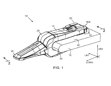
[028] Optionally, a front facing bearing wall on the wear member engages a
rear surface of
the lock received through the lock opening.
[029] In another embodiment a wear member for attaching to a digging edge
comprises a
front end and bifurcated legs extending rearwardly from the front end. Each of
the legs
including an inner surface to face the digging edge and a rear wall. At least
one of the legs
has a lock opening to receive a lock therein. At least one of the legs
includes a front portion
and a rear portion recessed relative to the front portion. The front portion
includes a rear facing
lateral wall adjacent the rear portion to oppose a wear cap receivable in the
recessed rear
portion. The rear portion includes at least one front facing lateral wall
forward of the rear wall
which is suitable for engaging a wear cap in the rear portion and resisting
rearward movement
of the wear cap.
[030] In another embodiment, a wear member for attaching to a digging edge
comprises a
front end and bifurcated legs extending rearwardly from the front end. At
least one of the legs
defines a lock opening to receive a lock therein, and a pair of indentations
to each side of the
lock opening, wherein each indentation includes a front facing wall for
resisting rearward
movement of a wear cap on the at least one leg.
[031] In another embodiment, a wear member for an earth working equipment
includes a
pair of legs defining a cavity therebetween for receiving a base of the
equipment. Each of the
legs includes an inside surface to face the base, an opposite outer surface to
face away from
the base, and a through-hole opening in the inside surface and the outer
surface. The hole in
each leg has a rear end defined by an end surface that extends away from the
base, wherein
the end surface in one leg extends from the inside surface to the outer
surface, and the end
surface in the other leg extends from the inside surface to a step proximate
the outer surface.
3
CA 03215171 2023- 10- 11
WO 2022/221217
PCT/US2022/024309
[032] In another embodiment, a wear member for an earth working equipment
includes at
least one leg having an inside surface to face the base, an outside surface, a
front end and a
rear end, wherein the rear end of the leg includes mounting recesses in the
outer surface for
mounting a wear cap.
[033] In accordance with another embodiment of the present invention, there is
provided a
wear member for attaching to a digging edge of a bucket, the wear member
comprising a front
end, bifurcated legs extending rearwardly from the front end, at least one of
the legs defining
a recessed shelf to receive a wear cap thereon, and a lock opening
therethrough to receive a
lock therein.
[034] The wear member may comprise a shroud.
[035] According to another embodiment of the present invention there is
provided a wear
assembly for attaching to a digging edge of a bucket, where the digging edge
defines a keyway
therethrough. The wear assembly comprises a wear member according to the above
embodiment and any desired optional features in the above paragraphs, a rear
wear cap
mounted on a rear portion of the wear member, a lock comprising a co-operating
spool and a
wedge mounted in the lock opening defined by the wear member and retaining the
rear wear
cap on the wear member.
[036] Optionally, the wear cap is mounted on a recessed rear portion of the
wear member
and defines a longitudinally extending opening in registration with the lock
opening, and a
profiled lower engagement surface.
[037] Optionally, the profiled lower engagement surface comprises a front
portion coupling
feature, engagement wings, and a rear boss feature.
[038] Optionally, the front portion coupling feature comprises a protrusion
extending beyond
an upper wear surface opposite the profiled lower engagement surface operable
to engage
with a complementary recess on a front portion of a wear member.
[039] Optionally, the front portion coupling feature comprises a recess
operable to engage
with a complementary protrusion on a front portion of the wear member.
[040] Optionally, each of the engagement wings comprises a rear facing wall
for abutting
against a corresponding front facing lateral wall located rearwardly on the
wear member, and
a downward facing surface aligned with a corresponding upward facing ledge
defined by the
wear member.
[041] Optionally, each of the engagement wings tapers towards a front portion
of the wear
member.
[042] Optionally, the rear boss feature comprises a rear facing wall for
aligning with a front
facing lateral wall defining the lock opening on the wear member.
4
CA 03215171 2023- 10- 11
WO 2022/221217
PCT/US2022/024309
[043] Optionally, the rear boss feature further comprises a tongue extending
towards the
lock opening and operable to locate beneath a corresponding protruding arm of
the spool so
that the spool prevents the rear wear cap from moving in the upward direction.
[044] In another embodiment, a wear assembly for earth working equipment
comprises a
wear member operable to couple to a digging edge of the earth working
equipment, a wear
cap configured to mount on the wear member, and a lock that secures the wear
member to
the digging edge and the wear cap to the wear member.
[045] In another embodiment, a wear assembly for attaching to a digging edge
comprises a
wear member including a front end and bifurcated legs extending rearwardly
from the front
end. Each of the legs includes an inner surface to face the digging edge and a
rear wall. At
least one of the legs has a lock opening to receive a lock therein. A wear cap
is mounted on
the wear member. A lock is in the lock opening to retain the wear cap on the
wear member
and the wear member on the digging edge.
[046] In another embodiment, a wear assembly for attaching to a digging edge
comprises a
wear member including a front end and bifurcated legs extending rearwardly
from the front
end. Each of the legs includes an inner surface to face the digging edge, an
outer surface
opposite the inner surface, and a rear wall. At least one of the legs
including a recess in the
outer surface, and at least one of the legs having a lock opening to receive a
lock therein. A
wear cap is mounted in the recess on the wear member. A lock is in the lock
opening to retain
the wear member on the digging edge.
[047] In another embodiment, a wear assembly for earth working equipment
comprises a
wear member operable to couple to the digging edge of a bucket or other
excavator, a wear
cap configured to mount on the wear member, and a lock that secures the wear
member to
the digging edge and also secures the wear cap to the wear member.
[048] In another embodiment, a wear assembly for earth working equipment
includes a wear
member having a pair of legs defining a cavity therebetween for receiving a
base of the
equipment. Each of the legs includes an inside surface to face the base, an
opposite outer
surface to face away from the base, and a through-hole opening in the inside
surface and the
outer surface that generally aligns with a keyway in the base. The hole in
each leg has a rear
end defined by an end surface that extends away from the base. A lock for
securing the wear
member to the base includes a spool and a wedge. The spool has a rearward-
facing bearing
surfaces to contact the end surfaces in the holes to resist forward motion of
the respective leg
during use without including arms on each end of the spool to contact step
surfaces between
the end surface and the outer surface in each of the legs.
[049] In another embodiment, a wear assembly for an earth working equipment
includes a
wear member having at least one leg with an inside surface to face a base of
the equipment,
and a lock having a wedge and a spool to secure the wear member to a base of
the equipment,
CA 03215171 2023- 10- 11
WO 2022/221217
PCT/US2022/024309
wherein the wedge includes two threaded tapering portions and a cylindrical
portion between
the tapering portions.
[050] According to another embodiment of the present invention, there is
provided a wear
cap for use with a wear member as part of a wear assembly, the rear wear cap
defining an
upper wear surface, a profiled lower engagement surface opposite the upper
wear surface,
and a longitudinally extending opening extending through the upper wear
surface and the
lower engagement surface, wherein the profiled lower engagement surface
comprises a front
portion coupling feature, engagement wings, and a rear boss feature.
[051] Optionally, the front portion coupling feature comprises a protrusion
extending beyond
the upper wear surface and operable to engage with a complementary formation
on a wear
member.
[052] Optionally, the front portion coupling feature comprises a recess
operable to engage
with a complementary protrusion on a wear member.
[053] Optionally, the front portion coupling feature is located generally
centrally at a front
portion of the rear wear cap.
[054] Optionally, each of the engagement wings comprises a rear facing wall
for abutting
against a corresponding front facing lateral wall located rearwardly on the
wear member.
[055] Optionally, each of the engagement wings tapers in mutually orthogonal
directions
towards a front portion of the wear member.
[056] Optionally, the rear boss feature comprises a rear facing wall for
aligning with a front
facing lateral wall partially defining the lock opening on the wear member.
[057] Optionally, the rear boss feature further comprises a tongue extending
towards the
lock opening and operable to locate beneath a corresponding protruding arm of
the spool so
that the spool prevents the wear cap from moving in the upward direction.
[058] In another embodiment, a wear cap for use with a wear member attached to
a digging
edge of a bucket comprises an upper wear surface, a lower surface opposite the
upper wear
surface to engage the wear member, an opening extending through the upper wear
surface
and the lower engagement surface, a front coupling formation to engage the
wear member to
retain the wear cap on the wear member, and a rear boss to engage a lock to
retain the wear
cap to the wear member.
[059] In another embodiment, a wear cap for use with a wear member to protect
a rear
portion thereof, the wear cap comprising an upper surface, a lower surface, a
lock aperture
extending through the upper and lower surfaces, a front coupling portion to
engage the wear
member and thereby retain the wear cap to the wear member.
[060] In another embodiment, a wear cap for use with a wear member attached to
a digging
edge comprises an upper wear surface, a lower surface opposite the upper wear
surface to
engage the wear member, and engagement wings extending inward from the upper
wear
6
CA 03215171 2023- 10- 11
WO 2022/221217
PCT/US2022/024309
surface, each including a rear facing bearing wall to engage a complementary
front facing
lateral wall on the wear member.
[061] In another embodiment, a wear cap for use with a wear member to protect
a rear
portion thereof, the wear cap defining an upper surface, a profiled lower
engagement surface,
and a longitudinally extending opening extending through the upper and lower
engagement
surfaces, wherein the profiled lower engagement surface includes a front
portion coupling
formation to engage the wear member and thereby retain the wear cap to the
wear member
[062] According to another embodiment, there is provided a wear cap for use
with a wear
member to protect a rear portion thereof, the wear cap defining an upper
surface, a profiled
lower engagement surface, and a longitudinally extending opening extending
through the
upper and lower engagement surfaces, wherein the profiled lower engagement
surface
comprises a front portion coupling feature.
[063] Optionally, the profiled lower engagement surface further comprises
engagement
wings and a rear boss feature.
[064] According to another embodiment of the present invention there is
provided a wear
assembly comprising a wear member for attaching to a digging edge of a bucket,
where the
digging edge defines a keyway therethrough, and a rear wear cap mechanically
attached to
the wear member. The wear member comprises a front end and bifurcated legs
extending
rearwardly from the front end. Each leg includes an inner surface to face the
digging edge, a
rear wall, and a lock opening therethrough to receive a lock. At least one of
the bifurcated legs
further comprises a front portion, a rear portion recessed relative to the
front portion, and a
coupling feature. The rear portion defines a stabilizing region comprising a
front facing lateral
wall forward of the rear wall. The wear cap comprises a longitudinally
extending opening
extending therethrough and in registration with the lock opening during use, a
front portion
coupling feature operable to engage with the coupling feature, and engagement
wings
operable to engage with the stabilizing region, wherein the wear cap may be
mechanically
attached to the wear member by a lock used to secure the wear member to the
digging edge.
[065] In another embodiment, a wear assembly for an earth working equipment
includes a
wear member having at least one leg with an inside surface to face a base of
the equipment,
a wear cap overlying at least a portion of the wear member, and a lock to
secure the wear cap
to the wear member and the wear member to the base.
[066] In another embodiment, a wear assembly for an earth working equipment
includes a
wear member having a pair of legs, each leg having an inside surface to face a
base of the
equipment, a first wear cap overlying at least a portion of one of the pair of
legs, a second
wear cap overlying at least a portion of the other of the pair of legs, and a
lock to secure at
least one of the wear caps to the wear member and the wear member to the base.
7
CA 03215171 2023- 10- 11
WO 2022/221217
PCT/US2022/024309
[067] In another embodiment of the present invention, there is provided a wear
assembly
comprising: a wear member operable to couple securely to the digging edge of a
bucket or
other excavator; a component mounted on the wear member; and a lock that
secures the wear
member to the digging edge and also secures the component to the wear member.
[068] Optionally, the lock comprises a multi-part lock. The multi-part lock
may comprise
multiple separate components that can be coupled and uncoupled. Alternatively,
the multi-
part lock may comprise multiple components that are coupled together but can
move relative
to each other to increase or decrease one or more external dimensions of the
multi-part lock.
[069] Optionally, the wear member comprises an adapter.
[070] Optionally, the adapter may define an aperture therethrough for aligning
with an
aperture defined by the digging edge, and the lock may be mounted in the
adapter and digging
edge apertures.
[071] Optionally, the component mounted on the adapter comprises a wear cap
such as a
rear wear cap.
[072] Optionally, the wear member comprises a shroud.
[073] Optionally, the component mounted on the shroud comprises a wear cap.
[074] Optionally, the component may surround an aperture defined by the wear
member.
[075] According to another embodiment of the present invention there is
provided a spool
for use in releasably securing separable components together, the separable
components
defining a lock opening for receiving the spool, the spool having an elongate
body extending
along a body axis from a head portion to a leg portion, and comprising (i) a
concave recess
defined by a front side thereof; (ii) a profiled surface on a rear side
thereof; (iii) a pair of arms
at the head portion and extending away from the body axis on the rear side;
and (iv) a pair of
shoulders at or near the head portion and extending between the front side and
the rear side.
[076] Optionally, the profiled surface on the rear side includes an angled
support located
beneath one of the pair of arms, and a bearing surface on the leg portion, for
engaging with a
digging edge.
[077] Optionally, the profiled surface on the rear side includes a head rear
surface for
engaging with a wear member.
[078] Optionally, the leg portion is substantially free of any protrusions so
that the spool can
be inserted into the lock aperture without the leg portion catching on a
digging edge or a wear
member prior to full insertion thereof.
[079] Optionally, the leg portion includes, at an end opposite the head
portion, an arm
extending away from the body axis on the rear side for engaging with a
complementary recess
in, or defined at least partially by, a wear member.
[080] Optionally, the concave recess on the front side defines a positive
thread for engaging
with a complementary recess thread on a wedge.
8
CA 03215171 2023- 10- 11
WO 2022/221217
PCT/US2022/024309
[081] Optionally, the concave recess on the front side defines a recess thread
for engaging
with a complementary positive thread on a wedge.
[082] Optionally, the concave recess on the front side defines an outer
surface generally
parallel to the body axis as the concave recess extends towards a lower
section of the leg
portion. Alternatively, the concave recess on the front side defines an outer
surface (i)
generally parallel to the body axis for part of its length, (ii) angled
towards the body axis for
part of its length, and optionally (iii) generally parallel to the body axis
for part of its length, as
the concave recess extends towards a lower section of the leg portion.
[083] Optionally, the lower section defines a limit stop extending away from
the body axis
and protruding into the concave recess to prevent a wedge from protruding
beyond the limit
stop.
[084] Optionally, the bearing surface slopes away from the body axis as it
extends to an
insertion end of the spool.
[085] Optionally, the pair of shoulders are formed on either side of, and at
or above, the lower
arm of the pair of arms.
[086] In another embodiment, a spool for use in releasably securing a wear
member to a
base for earth working equipment, the wear member and base cooperatively
defining a lock
opening for receiving the spool, the spool comprising an elongate body
extending along a
body axis. The body includes a head, a leg extending from the head, a front
side, a rear side,
and a pair of arms at the end with the head and extending away from the body
axis on the rear
side.
[087] According to another embodiment of the present invention there is
provided a wedge
for use in releasably securing separable components together, the separable
components
defining a lock opening for receiving the wedge, the wedge comprising: an
upper frusto-conical
portion, a lower frusto-conical portion, and a central cylindrical portion
between the upper and
lower frusto-conical portions; the upper and lower frusto-conical portions
defining an external
thread.
[088] Optionally, the diameter of the central cylindrical portion matches a
diameter of the
lowest part of the upper frusto-conical portion, and a diameter of the highest
part of the lower
frusto-conical portion.
[089] Optionally, the external thread comprises a negative thread recessed
therein.
[090] Optionally, the frusto-conical portions have the same external surface
taper angle.
[091] Optionally, the cylindrical portion is unthreaded and un-tapered.
[092] Optionally, a relatively wide, helically shaped land segment is formed
between
adjacent spiralling groove segments of the external thread.
9
CA 03215171 2023- 10- 11
WO 2022/221217
PCT/US2022/024309
[093] Optionally, the helically shaped land segment defines a first bearing
face to contact
one separable component and an opposite second bearing face to contact the
other separable
component to thereby resist loading between the wedge and the components.
[094] In another embodiment, a wedge for use in releasably securing a wear
member to a
base for earth working equipment, the wear member and the base cooperatively
defining a
lock opening for receiving the wedge, the wedge comprising an upper frusto-
conical portion,
a lower frusto-conical portion, and a central cylindrical portion between the
upper and lower
frusto-conical portions, wherein at least one of the upper and lower frusto-
conical portions
includes a thread.
[095] These and other embodiments of the present invention will be apparent
from the
following description, given by way of example only, with reference to the
following drawings.
BRIEF DESCRIPTION OF THE DRAWINGS
[096] FIG. 1 is a perspective view of a wear assembly mounted on a lip, in
accordance with
one embodiment of the present invention.
[097] FIG. 2 is a perspective partial cross-sectional view taken along line 2-
2 in FIG. 1.
[098] FIG. 3 is a perspective exploded view of the wear assembly and lip
portion of FIG. 1.
[099] FIG. 4 is a side view of the wear assembly of FIG. 1.
[100] FIG. 5 is a front view of the wear assembly of FIG. 1.
[101] FIG. 6 is a plan view from above of the wear assembly of FIG. 1.
[102] FIG. 7 is a plan view from below of the wear assembly of FIG. 1.
[103] FIG. 8 is a simplified side partial cross-sectional view corresponding
to the view shown
in FIG. 2 (without any cross hatching).
[104] FIGS. 9A and 9B are simplified views of a part (lip bosses) of the wear
assembly of
FIG. 1.
[105] FIG. 10 is a front perspective view of a part (a keyway insert) of the
wear assembly of
FIG. 1.
[106] FIG. 11 is a plan view from above of the keyway insert of FIG. 10.
[107] FIG. 12 is a front elevation view of the keyway insert of FIG. 10.
[108] FIG. 13 is a front perspective view from above of a wear member (in the
form of an
adapter) forming part of the wear assembly of FIG. 1.
[109] FIG. 14 is a side elevation view of the adapter of FIG. 13.
[110] FIG. 15 is a top plan view of the adapter of FIG. 13.
[111] FIG. 16 is a rear perspective view from below of the adapter of FIG. 13.
[112] FIG. 17 is a rear elevation view of the adapter of FIG. 13.
[113] FIG. 18 is a front elevation view of the adapter of FIG. 13.
[114] FIG. 19 is a rear perspective view from above of the adapter of FIG. 13.
CA 03215171 2023- 10- 11
WO 2022/221217
PCT/US2022/024309
[115] FIG. 20 is a front perspective view from above of another part (a rear
wear cap) of the
wear assembly of FIG. 1.
[116] FIG. 21 is a side elevation view of the rear wear cap of FIG. 20.
[117] FIG. 22 is a top plan view of the rear wear cap of FIG. 20.
[118] FIG. 23 is a below plan view of the rear wear cap of FIG. 20.
[119] FIG. 24 is a front elevation view of the rear wear cap of FIG. 20.
[120] FIG. 25 is a rear elevation view of the wear member of FIG. 20.
[121] FIG. 26 is a rear perspective view from above of another part (a spool
of a multi-part
lock) of the wear assembly of FIG. 1.
[122] FIG. 27 is a front perspective view from above of the spool of FIG. 26.
[123] FIG. 28 is a front elevation view of the spool of FIG. 26.
[124] FIG. 29 is a rear elevation view of the spool of FIG. 26.
[125] FIG. 30 is a rear perspective view from below of the spool of FIG. 26.
[126] FIG. 31 is a side elevation view of the spool of FIG. 26.
[127] FIG. 32 is a plan view from below of the spool of FIG. 26.
[128] FIG. 33 is a plan view from above of the spool of FIG. 26.
[129] FIG. 34 is a front elevation view of another part (a wedge for use with
the spool in a
multi-part lock) of the wear assembly of FIG. 1.
[130] FIG. 35 is a side elevation view of the wedge of FIG. 34 coupled to the
spool of FIG.
26.
[131] FIG. 36 is a plan view from above of the wedge of FIG. 34 coupled to the
spool of FIG.
26.
[132] FIG. 37 is a side elevation view of the wedge of FIG. 34 coupled to the
spool of FIG.
26 and the keyway insert of FIG. 10.
[133] FIG. 38 is an enlarged view of part of the partial cross-sectional view
of the wear
assembly shown in FIG. 8 prior to mounting of the rear wear cap of FIG. 20 and
insertion of
the wedge of FIG. 34.
[134] FIG. 39 is a view similar to FIG. 38 but during mounting of the rear
wear cap of FIG.
20 and prior to insertion of the wedge of FIG. 34.
[135] FIG. 40 is a view similar to FIGS. 38 and 39 but after mounting of the
rear wear cap of
FIG. 20 and prior to insertion of the wedge of FIG. 34.
[136] FIG. 41 is a simplified side view of an enlarged part (illustrated by
circle A) of the cross
sectional view of FIG. 8 after mounting of the rear wear cap of FIG. 20 and
insertion of the
wedge of FIG. 34.
[137] FIG. 42 is a front elevation view of a stepped spool as an alternative
to the spool of
FIGS. 26 to 33.
[138] FIG. 43 is a front perspective view from above of the stepped spool of
FIG. 42.
11
CA 03215171 2023- 10- 11
WO 2022/221217
PCT/US2022/024309
[139] FIG. 44 is a rear perspective view of a stepped keyway insert as an
alternative to the
a keyway insert of FIGS. 10 to 12.
[140] FIG. 45 is a front elevation view of a stepped wedge as an alternative
to the wedge of
FIG. 34.
[141] FIG. 46 is a front exploded perspective view from above of the stepped
spool of FIG.
43, the stepped wedge of FIG. 45, and the stepped keyway insert of FIG. 44.
[142] FIG. 47 is a rear exploded perspective view from above of the stepped
spool of FIG.
43, the stepped wedge of FIG. 45, and the stepped keyway insert of FIG. 44.
[143] FIG. 48 is a side elevation view of the stepped wedge of FIG. 45 coupled
to the stepped
spool of FIG. 43 and the stepped keyway insert of FIG. 44.
[144] FIG. 49 is a perspective exploded view of the wear assembly, in
accordance with yet
another embodiment of the present invention, in proximity to a lip portion.
[145] FIG. 50 is a perspective view of the wear assembly of FIG. 49 mounted on
the lip
portion.
[146] FIG. 51 is a front perspective view of part (a shroud) of the wear
assembly of FIG. 49.
[147] FIG. 521s a plan view from above of the shroud of FIG. 51.
[148] FIG. 53 is a front elevation view of the shroud of FIG. 51.
[149] FIG. 54 is a front perspective view of another part (a wear cap) of the
wear assembly
of FIG. 49.
[150] FIG. 55 is a plan view from above of the wear cap of FIG. 54.
[151] FIG. 56 is a front elevation view of the wear cap of FIG. 54.
[152] FIG. 57 is a front perspective view of another part (a multi-part lock)
of the wear
assembly of FIG. 49.
[153] FIG. 58 is a plan view from above of the multi-part lock of FIG. 57.
[154] FIG. 59 is a front elevation view of the multi-part lock of FIG. 57.
[155] FIG. 60 is an exploded front perspective view of the multi-part lock of
FIG. 57.
[156] FIG. 611s a plan view from above of the wear assembly and lip portion of
FIG. 50.
[157] FIG. 62 is a front sectional view along line 62-62 of FIG. 61.
[158] FIG. 63 is a simplified, enlarged front sectional view along line 62-62
of FIG. 61 during
insertion of the multi-part lock of FIG. 57.
DETAILED DESCRIPTION OF THE INVENTION
[159] Reference is first made to FIGS. 1 to 8, which show a wear assembly 10
and various
parts thereof, according to an embodiment of the present invention. The FIGS.
are simplified,
and some FIGS. have reduced detail, to facilitate understanding and to prevent
the views from
being cluttered.
12
CA 03215171 2023- 10- 11
WO 2022/221217
PCT/US2022/024309
[160] In the example of FIGS. 1 to 8, the wear assembly 10 is mounted on a lip
12 of a
bucket. Nevertheless, the wear assembly could be mounted to other digging
edges and/or
other earth working equipment.
[161] In FIG. 1 three mutually orthogonal axes are illustrated. These axes
comprise a
longitudinal (forward and rearward) axis (labelled LONG.), a lateral (side to
side) axis (labelled
LAT.) and a levitational (or up and down) axis (labelled LEV.). As used
herein, front and rear
are generally used with respect to the longitudinal axis shown in FIG. 1.
Likewise, up and down
are used to identify directions along the levitational axis, e.g., as when the
lip is oriented as in
FIG. 1
[162] The wear assembly 10 comprises a wear member 14 (in the form of an
adapter in this
embodiment) that mounts onto the lip 12, and a point or tip 16 that is mounted
on a front end
of the adapter 14. The wear assembly 10 further comprises an optional front
wear cap 20, an
optional rear wear cap 22, and a lock 24 that secures adapter 14 to the lip 12
and, when a
rear wear cap 22 is used, simultaneously secures the wear cap 22 to the
adapter 14. While
one example wear assembly is shown, teeth having other designs could be used.
As
examples, an intermediate adapter could be provided, other kinds of locks
could be used, etc.
[163] For ease of discussion, the mounting of an adapter 14 to a lip 12 of a
bucket is
disclosed herein. Nevertheless, in other embodiments the wear members 14 may
be shrouds,
wing shrouds, solid points, wear plates, and the like, and the support
structures may be digging
edges on other equipment such as dredge cutter heads, rolling drums, blades,
etc.
[164] In this embodiment, the lip 12 defines the digging edge of a bucket or
dipper of a cable
shovel and includes a leading surface 30, an inner face 32 and an outer face
34. A through-
hole or keyway 36 (best seen in FIG. 3) is provided in the lip 12 passing
through inner face 32
and outer face 34.
[165] The leading surface 30 is shown as a curved (or semi-circular) surface
to
accommodate part of the adapter 14, but other configurations are possible. The
leading
surface 30 may define a protrusion or a recess for engaging with a
complementary recess or
protrusion (respectively) of the adapter 14.
[166] While only a small portion of the lip 12 is shown in the drawings, the
lip 12 may include
a series of through-holes 36 for the mounting of other teeth to the bucket.
Various
constructions (not shown) could also be provided between through-holes 36 for
mounting
shrouds. Different shapes and configurations of keyways 36 are also possible.
The digging
edge may also extend upward from the lip along the front edges of the bucket
sidewalls and
be fitted with wing shrouds optionally provided with features of the adapter
or shroud
embodiments disclosed herein.
[167] The lip 12 further comprises a stabilization system 40. In the
illustrated embodiment,
the stabilization system 40 comprises an upper support or boss 42a, a lower
support or boss
13
CA 03215171 2023- 10- 11
WO 2022/221217
PCT/US2022/024309
42b, and a keyway insert 44, though other configurations including more or
fewer components,
and components having different shapes to those illustrated, are possible. Any
or all of these
components could be omitted.
[168] The stabilization system 40 increases the strength and/or stability of
the wear member
14 on the lip 12, leading to longer service life of the wear member 14 and/or
the lip 12 and/or
a reduced maintenance requirement on the lip 12.
[169] In the illustrated embodiment, the upper boss 42a, lower boss 42b, and
keyway insert
44 are secured to the bucket lip 12 via welding (labelled "W" in FIGS. 1 to
8).
[170] In other embodiments, the stabilization system may comprise other
components. In
one such example, one or more bosses or supports could be provided on the
leading surface
30 of the lip 12.
[171] In the illustrated embodiment, the bosses 42a, 42b are fixed to the lip
12 rearward of
and in alignment with the through-hole 36. Preferably, the upper boss 42a is
secured to extend
along inner face 32 of lip 12 and the lower boss 42b is secured to extend
along outer face 34
for each through-hole 36. Nevertheless, a single boss on the inner face 32 (or
outer face 34)
could be used, or alternatively, the bosses could be omitted. One or more
bosses could
alternatively or additionally be secured to the lip between the leading
surface 30 and through-
hole 36. A plurality of spaced bosses or supports could be provided to set
outside each adapter
leg on one or both sides of the lip in lieu of (or additionally) to central
bosses received in the
adapter legs 86a, 86b.
[172] Although the bosses 42a, 42b are preferably welded to the lip 12, they
could be formed
as an integral portion of the lip 12 or secured in other ways. The bosses 42a,
42b are
preferably cast in a harder alloy than the lip 12 to aid in reducing the rate
of wear in and
maintenance of the lip 12, but various alloys with the same or lesser hardness
could be used.
[173] In this embodiment, the bosses 42a, 42b are identical, but mounted on
opposite
surfaces 32,34 of the lip 12 so that they are mirror images of each other; in
other embodiments
a lower boss, if provided, may have a different configuration to the upper
boss.
[174] Reference will now also be made to FIGS. 9A and 9B, in which each boss
42a, 42b is
illustrated having a main body 50 receivable in a slot in the adapter, and a
rear member 62
rearward of the adapter.
[175] In the illustrated embodiment, main body 50 defines a central base 52
and laterally
extending flanges or rails 54 along each side of the central base, thereby
providing a T-shaped
configuration. The rear member 62 includes one or more abutment surfaces 56
for abutting a
rear end of the adapter 14 during digging, i.e., to resist the applied loads
and rearward shifting
of the adapter legs and so reduce the risk of adapter breakage. In FIGS. 1, 3,
4 and 8 the
welds are illustrated and labelled with a "W". Each boss 42 may be similar to
the bosses
14
CA 03215171 2023- 10- 11
WO 2022/221217
PCT/US2022/024309
described in U.S. Patent No. 6,986,216, although variations of the design
illustrated therein
may be used.
[176] The abutment surface 56 may include one or more inserts 58 for
additional hardness
and/or other desired property.
[177] The inner sides of the rails 54 define holding surfaces 60 that
generally face the lip 12
to hold the adapter 14 to the lip 12 and/or resist vertical spreading of the
adapter legs. The
rails 54 are preferably fixed to the abutment surface 56 for support. The
rails 54 may have a
dovetail or other shape to support adapter legs. Alternatively, the rails may
be omitted or
replaced with an alternative support.
[178] Although the bosses 42a, 42b have a one-piece construction in this
embodiment, they
may be defined by multiple parts coupled together or separately secured to the
lip. Further,
the main body 50 and/or rear member 62 may be used without the other. In the
illustrated
example, the rear member 62 is formed as part of its respective boss 42a, 42b,
but in other
examples the bosses 42a, 42b and rear member 62 may be formed as separate
pieces, or all
as part of the lip 12, which may be formed by casting or fabrication.
[179] Reference will now also be made to FIGS. 10 to 12, which show the keyway
insert 44
in more detail.
[180] As best seen in FIG. 10, keyway insert 44 has a generally C-shaped
configuration with
a central body 70 and an inner arm 72 and an outer arm 74 extending therefrom.
[181] In the illustrated embodiment, each of the arms 72, 74 includes a
central protrusion
72a, 74a extending along its respective arm 72, 74 and defining a recess 72b,
74b on either
side thereof to accommodate weld material (as shown in FIG. 3). Inner and
outer arms 72, 74
overlie and are welded to the inner and outer faces 32, 34, respectively, of
lip 12. Other
configurations and/or securing arrangements are possible.
[182] A rear surface 76 of central body 70 is arcuate to receive the front
side of a wedge
(described below). While rear surface 76 is preferably unthreaded, it could
optionally include
threads to engage the wedge in lieu of (or in addition to) the spool 180.
Other shapes of rear
surface are possible such as non-arcuate concave shapes or flat surfaces
(particularly if other
kinds of wedges are used such as, e.g., wedges driven by hammers or bolts).
[183] The keyway insert 44 may have a different shape to that described. For
example, a
similar shape to that shown in U.S. Patent No. 6,986,216 may be used, or
alternative shapes
may be used.
[184] Keyway insert 44 functions to provide a longer and more deformation
resistant bearing
surface against which a wedge can bear as compared with using just the lip 12
without the
keyway 44. The arms 72, 74 may be the same or different lengths to each other,
and may
include plug welds. The arms 72, 74 may be of one piece construction, or
composed of several
components (e.g. the outer arm 74 may be composed of two components). The arms
72, 74
CA 03215171 2023- 10- 11
WO 2022/221217
PCT/US2022/024309
may be longer and extend farther from through-hole 36 even up to leading
surface 30. With
the use of longer arms (or for other reasons), one or both of the arms 72, 74
may be separate
components welded to the lip 12 separate from the central body 70.
[185] The arms 72, 74 optionally provide additional side support for the
adapter 14 but could
be used to support just the keyway insert 44.
[186] Referring more particularly to FIGS. 13 to 19, the adapter 14 will now
be described.
The adapter 14 supports the point 16 and secures it to the lip 12.
[187] Adapter 14 has a front end 80 and a rear end 82. The front end 80
includes a forwardly
projecting nose 84 for mounting the earth-penetrating point 16. A pair of
bifurcated legs 86a,b
extend rearwardly from the front end 80 in a longitudinal direction and
straddle the lip 12. The
upper leg 86a is situated to engage the inner face 32 of the lip 12 and the
lower leg 86b is
situated to engage the outer face 34 of the lip 12.
[188] Each leg 86a, 86b includes an inner surface 88a, 88b facing the lip 12,
and defines a
rear wall 90a, 90b. In this embodiment, the legs 86a, 86b are of equal (or
approximately equal)
length (although in other embodiments the legs 86a, 86b may have different
lengths). A slot
92a, 92b is optionally provided in each of legs 86a, 86b to open in the rear
wall 90a, 90b and
inner surface 88a, 88b to receive a respective boss 42a, 42b.
[189] An internal lateral wall 94a, 94b projects into the slot 92a, 92b from
inner surface 95
(i.e., toward the lip 12) and optionally closes the front of the slots 92a,
92b. The slots are each
dimensioned and shaped to receive the flanges 54 of the upper (inner) and
lower (outer)
bosses 42a, 42b, respectively. That is, in the illustrated embodiment, the
sides of the slots
92a, 92b are provided with grooves to receive the rails on the sides of the
bosses 42a, 42b.
Each of the inner lateral walls 94a, 94b are axially spaced from the
respective boss 42a, 42b,
but could alternatively abut the boss to provide resistance to thrust loads.
Each respective
slot 92a, 92b cooperates with the received boss 42a, 42b to provide support to
the respective
adapter leg to resist shifting of the leg in side and/or upward/downward
directions.
[190] Each of the legs 86a, 86b includes a pair of opposite side surfaces 96a,
96b extending
longitudinally from near the nose 84 to the rear wall 90a, 90b. The legs 86a,
86b are connected
via a central portion 140 extending rearward from the front end 80 and have a
rearward facing
bearing surface 142. The front portion 144 of side surfaces 96a, 96b connects
legs 86a, 86b.
The pair of opposed side surfaces 96a, 96b may be bounded by one or more
support (not
shown) welded on or otherwise fixed to the lip 12 adjacent each side surface
96a, 96b. These
exterior supports (not shown) could be in lieu of internal supports 42a, 42b
and/or 72, 74.
[191] The bearing surface 142 abuts against the lip leading surface 30 when
the adapter 14
is mounted thereon. In the illustrated embodiment, bearing surface 142 is
curved to
complement the curved leading surface 30. It will be appreciated that various
designs of
leading surfaces on the lip 12 and a complementary bearing surface 142 on the
adapter 14
16
CA 03215171 2023- 10- 11
WO 2022/221217
PCT/US2022/024309
are possible. The above is merely given by way of example. For example, the
leading surface
30 may define a protrusion or a recess for engaging with a complementary
recess or protrusion
(respectively) of the adapter 14. As another example, the leading surface 30
and bearing
surface 142 could each be angular or have a non-uniform curve.
[192] The lower leg 86b defines an external lower surface 98 extending from a
rear portion
of the nose 84 to the rear end 82.
[193] The upper leg 86a defines an external upper surface 100 extending from a
rear portion
of the nose 84 to the rear end 82, and having a front portion 102 and a rear
portion 104. In the
illustrated embodiment, rear portion 104 is recessed relative to the front
portion 102 but it need
not be. The rear portion 104 has an outer surface 105. The front portion 102
defines a
rearward facing lateral wall 106 (best seen in FIG. 19) adjacent the rear
portion 104 to define
the front of the recessed rear portion 104.
[194] In the illustrated embodiment, the rearward facing lateral wall 106 has
a general C-
shape when viewed from above, defining a central portion 107a generally
parallel to the upper
leg rear wall 90a and side portions 107b, each side portion 107b extending
from the central
portion 107a towards its respective upper opposed side portion 96a and the
upper leg rear
wall 90a. Other configurations of the rearward facing lateral wall 106 are
also possible.
[195] The upper leg 86a (in this embodiment, the rear portion 104) defines a
lock opening
112. In the illustrated embodiment, lock opening 112 is elongated and includes
a narrowed
front portion 110 and a narrowed rear portion 114 (best seen in FIGS. 15 and
19), though
other shapes are possible. In this embodiment, lock opening 112 is located in
the rear portion,
but it could be in both front and rear portions or only in the front portion.
[196] The rear facing lateral wall 106 includes a projection 117 defining a
retaining surface
118 on an underside thereof. In the illustrated embodiment, projection 117 is
one the narrowed
front portion 110. Retaining surface 118 acts as a coupling formation to
retain a wear cap 22
to wear member 14.
[197] In this embodiment, the retaining surface 118 overlies a coupling
portion 163 on the
wear cap 22 (described in more detail below). In the illustrated embodiment,
coupling portion
163 is formed on a forwardly-extending tongue 163, but other embodiments are
possible. For
example, the projection 117 may be formed as a tongue with a retaining surface
118 for
overlying an upward-facing surface of the rear wear cap 22. A plurality of
retaining surfaces
118 could be provided on the adapter to retain the wear cap to the adapter.
The retaining
surface(s) 118 could be positioned at other locations besides the front end of
the wear cap.
[198] The retaining surface(s) 118 could optionally be biased (e.g., by an
elastomer) to
retract during installation of the wear cap and return to a retaining position
when the wear cap
is positioned in an installed position. Alternatively, the wear cap could
include biased a
coupling portion(s) that retracts during installation and returns to a
retaining position beneath
17
CA 03215171 2023- 10- 11
WO 2022/221217
PCT/US2022/024309
a retaining surface on the adapter when the wear cap is in an installed
position. While in the
illustrated embodiment, retaining surface(s) 118 cooperate with the lock to
retain the wear cap
22 to wear member 14 (described below), retaining surface(s) 118 could retain
the wear cap
without use of the lock.
[199] A step portion 125 of adapter 14 defines shelf 120 that is recessed from
the rear portion
outer surface 105. The shelf 120 defines a concave front facing surface 122
forming a bearing
surface; other shapes are possible. The shelf 120 extends forward into the
lock opening 108.
A front facing central lateral wall 124 extends from the shelf 120 to the rear
portion outer
surface 105. The space defined by shelf 120 and lateral wall 124 receives the
coupling portion
163 of wear cap 22.
[200] A lower portion of the longitudinally extending lock opening 112 defines
a pair of
optional ledges 126 (best seen in FIGS. 13 and 15), each on an opposing
longitudinal side
thereof, extending from the concave front facing surface 122 towards the
narrowed front
portion 110. As described in more detail below, the ledges 126 prevent the
spool 180 of lock
24 from falling through the lock opening 112.
[201] The central portion of lock opening 112 is similarly dimensioned to, and
is in
registration with, the through-hole 36 in the lip 12, and a lock opening 128
defined by the lower
leg 86b, to allow the lock 24 to fit therethrough, as described in more detail
below.
[202] The lower leg lock opening 128 is partially defined by a lateral wall
129 (forming a
bearing surface) located at a rear end thereof (best seen in FIG. 13). The
lateral wall 129
extends from the lower leg inner surface 95 to the lower leg external lower
surface 98, though
other arrangements are possible. For example, bearing surface 129 may extend
only partially
through lock opening 128. In another example, lock opening may could be closed
at its lower
end.
[203] The upper surface rear portion 104 defines a stabilizing formation 130
near the rear
end 82 including a front facing bearing wall 132 to resist rearward movement
of the wear cap
22. In the illustrated embodiment, the stabilizing formation comprises a pair
of indentations
130, each recessed relative to its respective upper opposed side surface 96a
and rear portion
outer surface 105. As best seen in FIGS. 13 and 14, each indentation 130
includes (i) a front
facing bearing wall 132, (ii) a curved upward facing surface 134 rising from
the front facing
bearing wall 132 towards the front portion 102 and merging with the rear
portion outer surface
105, and (iii) a longitudinal wall 136 extending between the curved upward
facing surface 134
and the rear portion outer surface 105, and tapering towards the front portion
102. Each
indentation 130 is located rearward of the front portion 102 and forward of
the upper leg rear
wall 90a.
[204] In other embodiments, the indentations 130 may have a different shape,
or a different
location, or the stabilizing formations may comprise protrusions rather than
recesses. In other
18
CA 03215171 2023- 10- 11
WO 2022/221217
PCT/US2022/024309
embodiments, the rear portion 104 may not be recessed relative to the front
portion 102. In
other embodiments, the front facing bearing wall(s) can be provided otherwise.
In one
example, front facing lateral wall 124 could resist rearward movement of the
wear cap 22. In
another example, a front facing lateral wall could be provided at the rear end
of the wear cap
22 (not shown).
[205] In the illustrated embodiment, a groove 131 extends along each of the
outer sides of
upper surface 100 of adapter leg 86a between the rear wall 90a and the
respective indentation
130 to receive the sidewalls 171 of wear cap 22 to resist side loads on the
wear cap.
Alternatively, grooves 131 could be omitted such that sidewalls 171 extend
along side surfaces
96a of leg 86a. Support for wear cap 22 to resist side loads could be
otherwise provided.
[206] In the illustrated embodiment, wear cap 22 is captured and retained
against upward
movement by retaining surface 118 of wear member 14 at a forward portion of
wear cap 22
and by a retaining surface 194 of lock 24 at a rearward portion of the wear
cap (as described
below). The wear cap 22 is preferably not held tightly against the wear member
by retaining
surfaces 118, 194.
[207] The wear cap 22 will now be described in more detail with reference to
FIGS. 20 to 25.
The wear cap 22 is formed from steel or other hard material, preferably harder
than the
material comprising the adapter 14. Wear cap 22 could optionally be formed as
a composite
member with an outer wear resistant surface.
[208] The rear wear cap 22 is configured to mount on the rear portion 104 of
the adapter 14
to provide protection against wear, but could be mounted at other locations in
lieu of or in
addition to on rear portion 104, e.g., on front portion 102 and/or lower leg
86b. In the illustrated
embodiment, the upper wear surface 150 of the wear cap is aligned with or
recessed from the
outer surface of the front portion to minimize additional loading and/or
wearing of the wear cap
22. Nevertheless, the rear portion 104 need not be recessed. For example, the
rear portion
could have the same extension as front portion 102 (or raised above front
portion) with the
wear cap set over adapter leg 86a.
[209] The rear wear cap 22 preferably has a generally C-shaped configuration
with a central
wear panel to overlie atop of adapter leg 86a and opposite sidewalls 171 to
extend along the
sides of leg 86a and fit in grooves 131. The bottom ends of sidewalls 171 are
preferably
spaced from adapter 14, but could alternatively engage the adapter. Sidewalls
171 could be
omitted and side support otherwise provided such as by the sides of the wear
cap. In the
illustrated embodiment, wear cap 22 comprises an upper wear surface 150, a
profiled lower
engagement surface 152 facing leg 86a, an opening 154 extending through the
upper wear
surface 150 and the lower engagement surface 152, a front coupling portion
156, engagement
wings 158, and a rear coupling portion 160 (best seen in FIG. 25). In other
embodiments,
wear cap 22 may have different configurations.
19
CA 03215171 2023- 10- 11
WO 2022/221217
PCT/US2022/024309
[210] In this embodiment, the front coupling portion 156 comprises a front
facing wall 161
having a protrusion or tongue 163 at a lower portion thereof and extending
forwards of the
front facing wall 161 and beyond the upper wear surface 150. The coupling
portion 156 is
configured to engage with a complementary coupling formation (e.g., projection
117) on the
adapter 14. The protrusion 156 may be located generally centrally on the rear
wear cap 22
(when viewed from above or below, i.e. generally central in a lateral
direction).
[211] In other embodiments, the projection 156 may be split into two or more
forward
protrusions. In other embodiments, the front portion coupling portion may
comprise a recess
operable to engage with a complementary protrusion on the adapter. In other
embodiments,
the coupling portion may be a portion of the wear surface 150 over which
retaining surface
118 extends.
[212] Each of the engagement wings 158 extends down from sidewalls 171 and is
complementarily received in a respective indentation 130 on the adapter 14.
Each
engagement wing 158 comprises a rear facing bearing wall 162 for abutting the
corresponding
front facing bearing wall 132 to resist rearward movement of the wear cap.
Each engagement
wing 158 also includes a downward facing surface 164 that opposes the
corresponding
upward facing surface 134. In the illustrated embodiment, downward facing
surface 164 is
spaced from upward facing surface 134, though they could contact. Each of the
engagement
wings 158 tapers both laterally (towards the respective side 136) and upwardly
(towards the
upper wear surface 150 of the rear wear cap 22) as the engagement wing 158
extends towards
the front wall 168. Other shapes are possible. Alternatively, engagement wings
158 could be
recesses in sidewalls 171 that receive complementary projections on the
adapter.
[213] In the illustrated embodiment, the upper wear surface 150 extends from a
rear wall
166 extending the full width of the wear cap 22 to a front wall 168 having a
general C-shape,
complementary to the C-shape profile of the rearward facing lateral wall 106.
That is, the front
wall 168 comprises a narrowed central portion 169a and side portions 169b
extending from
either side 171 of the wear cap 22 to the narrowed central portion 169a. The
front wall 168
has a complementary shape to the rearward facing lateral wall 106. The front
and rear edges
of wear cap 22, though, could have other shapes.
[214] The rear coupling portion 160, in the illustrated embodiment, includes a
boss extending
downward from upper wear surface 150 to set on or oppose shelf 120. Boss 160
has a
forwardly extending tongue 172 to be retained by lock 24, and a generally
central, rear facing
wall 170 opposing the front facing central lateral wall 124 (best seen FIGS. 8
and 40). The
tongue 172 is configured to locate beneath a corresponding retaining surface
194 of lock 24
(described in more detail below) so that the lock resists the wear cap 22 from
moving in the
upward direction away from the wear member.
CA 03215171 2023- 10- 11
WO 2022/221217
PCT/US2022/024309
[215] The rear wear cap 22 further comprises a front facing wall 174 extending
from an upper
surface of the tongue 172 to the upper wear surface 150.
[216] The rear boss feature 160 further comprises side walls 176 extending
from opposing
sides of the rear facing wall 170 to the forward facing tongue 172.
[217] In the illustrated embodiment, lock 24 includes a spool 180 and wedge
240. Reference
is now made to FIGS. 26 to 33, which illustrate part of the multi-part lock
24, namely a spool
180, in more detail.
[218] The spool 180 comprises an elongate body 182 defining a body axis 184,
and having
a head 186 and a leg 188 extending from the head generally along the body axis
184. When
viewed from the front or rear, the body axis 184 is aligned with a vertical
axis 185 (the
levitational axis in FIG. 1), but when viewed from either side, the body axis
184 is offset from
the vertical axis 185 by a small angle with the bottom end of leg 188 forward
of head 186. The
small angle may be between 2 degrees and 10 degrees from the vertical. Other
offset angles
are possible (larger or smaller), or the body axis may be vertical (i.e.
without any appreciable
offset).
[219] The head 186 optionally protrudes beyond the leg 188 in the lateral
direction (labelled
"LAT." in FIG. 28 (showing the front side of the spool 180) and FIG. 29
(showing the rear side
of the spool 180)) and forms a pair of shoulders 190, each having a similar
dimension (and
preferably a complementary formation) to each of the ledges 126 of the adapter
14. In other
embodiments, the surface of the shoulder 190 may not be complementary to the
surface of
the respective extended slot ledge 126. Different configurations are also
possible. The
shoulders 190 may also be omitted.
[220] Spool 180 preferably includes two arms 192, 196 to capture a portion of
the wear cap
22 and a portion of the wear member 14. Nevertheless, one retaining surface
194 such as one
upper arm 192 could be used to retain the wear cap. Both arms could be
omitted, e.g., if the
retaining surface 194 is formed in a recess in the spool to receive a portion
of the wear cap or
if the wear cap is retained by other retaining surfaces on the adapter without
the cooperation
of the lock.
[221] In the illustrated embodiment, the wear cap is retained to the wear
member by at least
one retaining surface 118 on the wear member and at least one retaining
surface 194 on the
lock. Nevertheless, the wear cap could be retained by at least one retaining
surface only on
the adapter or at least one retaining surface only on the lock.
[222] In the illustrated embodiment, the head 186 defines an upper arm 192 at
an upper
portion thereof. The upper arm 192 extends rearward in a longitudinal
direction (labelled
"LONG." in FIG. 31). While the rear end 195 of upper arm 192 is shown as
having a convex
profile when viewed from above or below, it could have any shape. The upper
arm 192 defines
21
CA 03215171 2023- 10- 11
WO 2022/221217
PCT/US2022/024309
a retaining surface 194 on a lower portion thereof to overlie tongue 172 and
retain wear cap
22 on adapter 14.
[223] In the illustrated embodiment, the leg 188 defines a lower arm 196 at an
upper portion
thereof. Nevertheless, arm 196 could be provided on the head 186. The lower
arm 196
extends in the same longitudinal direction as the upper arm 192, and also has
a convex end
surface 199 when viewed from above or below but could have any shape. The
lower arm 196
defines an engagement surface 198 on an upper portion thereof. The retaining
surface 194
and engagement surface 198 are optionally parallel to each other and are of
similar
dimensions. The lower arm engagement surface 198 is at approximately the same
height as
the shoulders 190. The lower arm 196 also defines, lower in this embodiment,
angled lower
surface 200 that opposes lip 12. Regardless of the particular shapes, spool
arms 192, 196
receive and capture tongue 172 of wear cap 22 and step portion 125 of adapter
14. In
embodiments where a rear wear cap is not used, the step portion 125 of the
adapter can fill
the space between upper arm 192 to lower arm 196 of spool 180. In such an
arrangement,
the step portion may be enlarged and/or the gap between the spool arms
reduced. Other
arrangements without a rear wear cap are possible including, for example, a
spacer used in
place of the wear cap, a gap existing between the step portion and one or both
spool arms,
the elimination of one or more spool arms, etc.
[224] The upper and lower arms 192, 196 preferably extend generally
perpendicular to the
vertical axis 185, though other extensions are possible.
[225] The head 186 defines a rear surface 201 having a slightly convex profile
(but other
shapes, such as a planar surface, are possible) and extending between the
upper arm 192
and the lower arm 196. When mounted on the adapter 14, the rear surface 201
engages with
the step portion 125 of the adapter 14 to resist forward movement of the
adapter 14 from lip
12. Rear surface 201 also opposes the front end of tongue 172 of the rear wear
cap 22 (best
seen in FIGS. 8 and 40). Rear surface 201 of spool 180 is preferably spaced
from tongue 172,
but contact could be made.
[226] Side surfaces 202 of the leg 188 extend generally parallel to the body
axis 184 (and
the vertical axis 185) for the length of the leg 188.
[227] A rear surface 204 (best seen in FIG. 29) of the leg 188 extends
generally parallel to
the body axis 184 (which is longitudinally offset from vertical) along a
middle section 206 of
spool 180, extending from a lower part of the lower arm 196 to a lower section
208. In this
embodiment, both the middle section 206 and lower section 208 of the rear
surface 204 define
slightly convex surfaces, but other surface profiles are possible. The lower
section 208 defines
a bearing surface 210 to contact lower leg 86b.
22
CA 03215171 2023- 10- 11
WO 2022/221217
PCT/US2022/024309
[228] In the illustrated embodiment, the bearing surface 210 slopes rearwardly
from a lower
part of the middle section 206 to a foot 212 of the spool 180 and is generally
parallel to the
vertical axis 185.
[229] In this embodiment, the head 186 and leg 188 have a single (unitary)
construction, but
in other embodiments, they may be separate parts that are coupled together.
Other shapes
of spool 180 are possible.
[230] A front surface 214 of the spool 180 preferably extends generally
parallel to the body
axis 184 (which is longitudinally offset from the vertical axis 185) from a
top 216 of the spool
180 to a bevel portion 218 near the bottom of the leg 188. The bevel portion
218 slopes
rearwards and extends to the foot 212 at the bottom of the leg 188.
[231] The junction of the bevel portion 218 and the foot 212 is on or near the
body axis 184
(although in other embodiments this may not be the case).
[232] In the illustrated embodiment, the front surface 214 defines an arcuate,
concave recess
220 extending from the top 216 towards, and then partially beyond the start
of, the bevel
portion 218. A positive screw thread 222 formed of spaced helical ridges is
provided on the
arcuate recess 220, extending from a lower part of the head 186 to above the
bevel portion
218, though other thread formations are possible. An optional screw thread
stop 224 is
provided at the lowest part of the positive screw thread 222 to prevent a
wedge (described in
more detail below) from being screwed beyond the stop 224. Front surface 214
could have
other configurations to complement other kinds of wedges or other drivers.
[233] In this embodiment, the middle and lower sections 206, 208 of the leg
188 are free of
any lateral or longitudinal protrusions. This has the advantage that the leg
188 can be easily
inserted into the longitudinally extending opening 154 in the rear wear cap
22, the lock opening
112 of the adapter upper leg 86a, the through-hole 36 of the lip 12, and the
lock opening 128
of the adapter lower leg 86b, as will be described in more detail below. Also
as described
below, the wear cap 22 may be installed after insertion of spool 180.
[234] However, in other embodiments, it may be desirable to add a lower arm
(not shown)
at or near either the lower part of the middle section 206 or an upper part of
the lower section
208. This lower arm could help resist forces on the adapter 14 by engaging
with (coupling to)
the outer face 34 of the lip 12 or a feature defined by the adapter lower leg
86b.
[235] Reference is now also made to FIGS. 34 to 38, which illustrate, inter
alia, the other part
of the 24 of this embodiment, namely a wedge 240, in more detail.
[236] The wedge 240 comprises a cylindrical portion 246 having an external
surface taper
angle 248, which in this embodiment is approximately 3 degrees (although a
smaller or larger
taper angle is possible) relative to the vertical axis 185. The taper angle
248 is illustrated in
FIG. 34 using a vertical broken line 252.
23
CA 03215171 2023- 10- 11
WO 2022/221217
PCT/US2022/024309
[237] The cylindrical portion 246 defines an external negative thread (in the
form of a helical
groove having a relatively wide pitch) 254 recessed therein, though other
thread formations
could be used.
[238] A relatively wide, helically shaped land segment 256 is formed between
adjacent
spiralling groove segments of the negative thread 254.
[239] In one embodiment, the pitch of the thread 254 on the wedge 240 is
approximately one
inch (25mm) and the width of the thread is approximately 1/8 of an inch (3mm),
although the
pitch and width could be selected from a range of suitable values. The thread
254 is preferably
formed with curved corners to form a robust thread that is not susceptible to
peening or other
damage. The upper (or rear) end 258 of the wedge 240 defines a turning
formation 260
recessed therein to facilitate engagement with a tool, such as a wrench, for
turning the wedge
240. In the preferred embodiment, formation 260 is a square socket, although
other
arrangements could be used.
[240] The taper angle 248 can be selected to provide a desired take-up of the
adapter 14 on
the support structure, e.g., the lip 12. For example, if the taper angle 248
is increased, the
rate at which the adapter 14 moves to the set position on the support
structure is increased,
but at the expense of tightening force (i.e., more torque is required to turn
the wedge 240);
conversely, if the taper angle 248 is decreased, the rate at which the adapter
14 moves to the
set position on the support structure is decreased, but the tightening force
is reduced. The
taper angle 248 can be designed to match the particular task. In most cases,
it is expected
that the holding power of the lock 24 would be approximately the same provided
the wedge
240 is not formed with too small a diameter at the forward (or lower) end 262
to provide
sufficient strength.
[241] As best seen in FIG. 37, which shows the wedge 240 received into the
recess on the
keyway insert 44 and into the recess 220 in the spool 180 and screwed into the
thread 222 on
the spool. The land segment 256 (between adjacent portions of the thread 248)
provides a
large surface area to press against both the rear surface 76 of the keyway
insert 44 and the
front surface 214 of the spool 180. The relatively large land segment 256
enables the lock 24
(comprising the spool 180 and wedge 240) to resist large loads with acceptable
levels of stress
and without the need for threads to be formed in a wall of the keyway 36 of
the lip 12. The
relatively wide pitch of the thread 254 also permits the wedge 240 to be
quickly moved into
and out of the spool 180.
[242] Installation of the wear assembly 10 will now be described with
particular reference to
FIGS. 38 to 40, which show a small portion of the wear assembly 10 in enlarged
view prior to
mounting of the rear wear cap 22, during mounting of the rear wear cap 22, and
after mounting
the rear wear cap 22, respectively. FIG. 41 illustrates in enlarged detail a
part of the wear
assembly 10 of FIG. 8 once the lock 24 has been fully installed.
24
CA 03215171 2023- 10- 11
WO 2022/221217
PCT/US2022/024309
[243] To mount the adapter 14, it is rearwardly slid onto the lip 12 with the
upper leg 86a
above the inner face 32 and the lower leg 86b below the outer face 34 so that
the upper leg
slot 92a slidingly engages with the upper boss 42a such that the slot 92a
encloses the flanges
54 of the upper boss 42a. Similarly, the lower leg slot 92b slidingly engages
with the lower
boss 42b such that the slot 92b encloses the flanges 54 of the lower boss 42b.
[244] When mounted in this way, the adapter 14 is positioned at the correct
location on the
lip 12, with the upper leg lock opening 112 is in registration with the lip
through-hole (or
keyway) 36 and the lower leg lock opening 128.
[245] Once the adapter 14 is correctly positioned, the spool 180 is inserted
(with the foot 212
and the bevel portion 218 as the leading surfaces) into the lock opening 112,
the lip through-
hole (or keyway) 36, and the lower leg lock opening 128. At this point,
shoulders 190 of the
spool 180 rest on the extended ledges 126 of the adapter 14, thereby
preventing the spool
180 falling through the upper leg lock opening 112.
[246] By moving the spool 180 forwards (in the direction of arrow C in FIG.
39), the wear cap
22 can be mounted on the adapter 14 by moving the wear cap 22 downwards (in
the direction
of arrow B in FIG. 38) and pivoting the front portion coupling structure 156
downwards and
engaging it beneath the retaining surface 118 of the adapter 14. The rear wall
166 of the wear
cap 22 can then be lowered towards the adapter 14 so that profiled lower
engagement surface
152 of the wear cap 22 sets over the rear portion 104 of the upper surface
100. In particular,
the forward facing tongue 172 sets on or over the shelf 120 of the adapter 14,
the wear panel
of wear cap sets on outer surface 105 of rear portion 104, and the rear facing
walls 162 of the
engagement wings 158 oppose the front facing bearing walls 132 of the
indentations 130 of
the adapter 14.
[247] The downward facing surfaces 164 of the engagement wings 158 are
position in
proximity to the upward facing ledges 134 of the adapter 14, but they may
remain spaced
apart. The rear facing wall 170 of the wear cap 22 are also in proximity to
the front facing
central lateral wall 124, but may remain spaced apart.
[248] The spool 180 can then be moved rearwards (in the direction of arrow D
in FIG. 40),
so that the following occurs: (i) the upper arm 192 and the lower arm 196
capture tongue 172
of wear cap 22 and step portion 125 of adapter 14 between them such that the
retaining
surface 194 of the upper arm 192 slides over, and remains above, the forward
facing tongue
172 (of rear boss feature 160) of the rear wear cap 22; (ii) the rear surface
201 of the head of
spool 180 abuts against the front-facing surface 122 of step portion 125 of
adapter 14; (iii) the
engagement surface 198 of the lower arm 196 slides under, and remains beneath,
the step
portion 125 of the adapter 14; and (iv) the bearing surface 210 of spool leg
188 abuts against,
or is in proximity to, a forward facing portion of the lower leg 86b defining
the lock opening
128.
CA 03215171 2023- 10- 11
WO 2022/221217
PCT/US2022/024309
[249] It may be preferred to mount the wear cap 22 prior to inserting the
spool 180. In such
a case, the spool 180 is inserted through the longitudinally extending opening
154 in the wear
cap 22, the lock opening 112, the lip through-hole (or keyway) 36, and the
lower leg lock
opening 128. Regardless of whether the spool 180 is inserted prior to or after
the wear cap 22
is mounted, the remaining arrangement of the parts is the same.
[250] The wedge 240 is inserted through the opening 154 in the wear cap 22. A
wrench (or
other convenient tool) is used to engage the turning formation 260 and to
rotate the wedge
240 so that the thread 254 on the wedge engages with the complementary threads
222 on the
spool 180. As the leading end 262 of the wedge 240 moves towards the thread
stop 224, the
wedge 240 urges the spool 180 rearwards. The screwing of the wedge continues
until the
wedge 240 tightens to a set level of torque with rear surface 201 of spool 180
pressed against
front wall 122 of step portion 125 of adapter 14, and rear surface 210 of
spool 180 pressed
against front facing wall of lock opening in lower leg 86b. Nevertheless, it
is possible when
assembled that one of the rear surfaces 201 or 210 could remain spaced from
its
complementary bearing surface on the adapter and contact when loads are
applied to the
adapter and/or wear occurs.
[251] As best seen in FIG. 41, insertion of the wedge 240 ensures that the
rear wear cap 22
is retained on the adapter 14, and simultaneously ensures that the adapter 14
is retained on
the digging edge 12. That is, tongue 163 sets under the retaining surface 118
on adapter 14
and tongue 172 sets underneath retaining surface 194 on lock 24 (Le., the arm
192 of spool
180) to resist upward movement of the retainer away from the adapter (along
the levitational
axis). Since the wear cap is preferably not tightly held in place, the wear
cap may rattle
somewhat between the wear member and lock surfaces that contain the wear cap.
[252] In the illustrated embodiment, lateral forces on the wear cap are
primarily resisted by
the inner surfaces of arms 171 bearing against the vertical walls of grooves
131 in the adapter.
[253] To remove the adapter 14, the wedge 240 is turned counter-clockwise to
drive the
wedge 240 upward so that it can be lifted out of the wear assembly 10. The
spool 180 is then
moved forwards (in the direction of arrow C in FIG. 39) so that the upper and
lower arms 192,
196 disengage from the tongue 172 of the rear wear cap 22 and the upper leg
86a of the
adapter 14. The rear wear cap 22 can then be pivoted upwards and removed from
the wear
assembly 10, in the reverse process to that described with reference to FIGS.
38 to 40.
[254] The spool 180 can then be removed from the wear assembly 10, and the
adapter 14
can then be pulled from the lip 12.
[255] The front wear cap 20, if used, can be mounted and removed in a
conventional manner.
[256] An alternative embodiment of the lock 324 will now be described with
reference to
FIGS. 42 to 48.
26
CA 03215171 2023- 10- 11
WO 2022/221217
PCT/US2022/024309
[257] FIG. 42 is a front elevation view of a stepped spool 280 as an
alternative to the spool
180. The primary difference between the spool 180 and the stepped spool 280 is
that the
stepped spool 280 has an arcuate recess 320 on a front side comprising (i) a
first portion 320a
extending generally parallel to the body axis 184 for part of its length, (ii)
a second portion
320b angled towards the body axis 184 for part of its length, and (iii) a
third portion 320c
extending generally parallel to the body axis 184 for part of its length, as
the arcuate recess
320 extends towards the lower section 208 of the leg 188. In contrast, the
arcuate recess 220
on the spool 180 is generally parallel to the body axis 184 along its length.
[258] In embodiments where the stepped spool 280 is used, it is preferred to
have a stepped
keyway insert 344, as illustrated in FIG. 44.
[259] The primary difference between the keyway insert 44 and the stepped
keyway insert
344 is that the stepped keyway insert 344 has a rear surface 376 comprising
(i) a first portion
376a extending generally parallel to the body axis 184 for part of its length,
(ii) a second portion
376b angled towards the body axis 184 for part of its length, and (iii) a
third portion 376c
extending generally parallel to the body axis 184 for part of its length. In
contrast, the keyway
insert rear surface 76 is generally parallel to the body axis 184 along its
length.
[260] The stepped spool 280 and stepped keyway insert 344 are preferably used
with a
stepped wedge 340, as illustrated in FIG. 45.
[261] The primary difference between the wedge 240 and the stepped wedge 340
is that the
stepped wedge 340 comprises an upper frusto-conical portion 342, a lower
frusto-conical
portion 344, and a central cylindrical (or other shaped) portion 346 between
the upper and
lower frusto-conical portions 342, 344. The diameter of the central
cylindrical portion 346
matches the diameter of the lowest part of the upper frusto-conical portion
342, and the highest
part of the lower frusto-conical portion 344. The frusto-conical portions 342,
344 have the
same external surface taper angle 348, which in this embodiment is
approximately 5 degrees
(although a smaller or larger taper angle is possible) relative to the
vertical axis 185. The taper
angle 348 is illustrated in FIG. 45 using a vertical broken line 352.
[262] In a similar way to wedge 240, the external negative thread (in the form
of a helical
groove having a relatively wide pitch in this example) 254 extends
substantially for the entire
length of the stepped wedge 340, though other kinds of thread could be used.
The thread
continues from the upper frusto-conical portion 342, across the cylindrical
portion 346 (also
referred to as a step portion), and then along the lower frusto-conical
portion 344. However,
in other embodiments, the cylindrical portion 346 may be unthreaded. In
another embodiment,
only one of the frusto-conical portions of the wedge could be threaded. In
another
embodiment, the central portion does not contact the spool 280 and/or the
front support 344.
Having the cylindrical portion 346 allows a wider taper (a larger taper angle
348) on the frusto-
27
CA 03215171 2023- 10- 11
WO 2022/221217
PCT/US2022/024309
conical portions 342, 344 without reducing the diameter of the wedge 340,
which could lead
to an increased risk of the wedge 340 breaking during use.
[263] When the lock 324 is assembled, as shown in FIG. 48, the upper frusto-
conical portion
342 of the wedge 340 aligns with both the first portion 320a of the spool 280
(on the rear side),
and the first portion 376a of the stepped keyway insert 344 (on the front
side). Similarly, the
lower frusto-conical portion 344 of the wedge 340 aligns with both the third
portion 320c of the
spool 280 (on the rear side), and the third portion 376c of the stepped keyway
insert 344 (on
the front side). The central cylindrical portion 346 of the wedge 340 aligns
with both the second
portion 320b of the spool 280 (on the rear side), and the second portion 376b
of the stepped
keyway insert 344 (on the front side).
[264] Providing the wedge with complementary stepped components allows for
more take
up and/or more securely holding the adapter 14 to the lip 12.
[265] Locks 24, 324 have a number of advantages. For example, lock 24, 324
directly retains
two components (the wear member 14 and the rear wear cap 22), whereas prior
art locks
directly retain one of the wear member or wear cap. The lock 24, 324 provides
retention in
two orthogonal directions, i.e., it holds the wear member 14 back into the
digging edge 12,
and it holds wear cap 22 from moving up from the wear member 14.
[266] The lock 24, 324 is only required to hold the rearward portion of the
wear cap 22
vertically downwards, all other loads are directed to stabilizing surfaces.
The lock 24, 324 is
isolated from loads applied to the rear wear cap 22. Failure of the rear wear
cap 22 will not
jeopardize the primary function of the lock 24, 324 to secure the adapter 14
to the lip 12.
[267] The method of installation for the disclosed embodiments is to pivot (or
rotate) the wear
cap 22 into place (compared with prior art wear caps that require linear
installation, i.e., with
wear cap rails being moved through grooves on the adapter). The rear wear cap
22 is
removed in a direction orthogonal to material flow (vertically up), which
means that the rear
wear cap 22 rotates / pivots then pulls straight away from the adapter 14 (and
any fines
therebetween or thereon) instead of sliding on a rail.
[268] The lock 24, 324 retains the rear wear cap 22 in a direction orthogonal
to material flow.
The multi-part lock 24, 324 has stabilizing features which prevent excess
migration of any part
of the lock 24, 324 if the rear wear cap 22 is lost.
[269] Other advantages of this embodiment relate to the spool 180, 280. The
spool 180,
280 only requires arms at the upper end of the spool. Any engagement on
adapter lower leg
86b is limited for rearward longitudinal force (into the bucket) and forward
motion of the adapter
lower leg 86b. The spool 180, 280 has features (e.g., shoulders 190) that
prevent it from
falling through the adapter 14 during installation and removal. The spool 180
is retained in a
way that allows it to slide longitudinally forward, thereby releasing the rear
wear cap 22.
28
CA 03215171 2023- 10- 11
WO 2022/221217
PCT/US2022/024309
[270] The lock 24, 324 installs and removes from the upper side of the lip 12
only, and it will
not fall through to the underside of the bucket. This improves safety of
personnel in installing
and, particularly, removing the adapter 14. Convenient sliding of spool 180,
280 after removal
of the wedge 240, 340 allows the rear wear cap 22 to be changed without
removal of the spool
180, 280. Vertical retention features are only provided on the adapter upper
leg 86a. There
is no need to pry the bottom of the spool 180, 280 rearward to release
engagement with
adapter 14. There are fewer system components, and a simpler installation and
removal
process, compared with having a dedicated lock for the rear wear cap 22. The
lock 24, 324
may be usable in multiple GET configurations (for example, with or without a
rear wear cap
22).
[271] Other lock arrangements may be used than the ones described above. For
example,
a similar design of wedge and spool arrangement to that shown in U.S. Patent
No. 6,986,216
may be used, or alternative designs may be used. Wedges driven by a hammer,
bolts or other
arrangements could be used instead of a threaded wedge and spool. Other locks
without a
wedge or spool could be used. The lock may comprise one or more than two
components.
[272] The design of the above embodiment has various manufacturing benefits
including, for
example, reduced fit requirements for the adapter lock combination. Fit areas
are more
localized in the upper leg 86a of the adapter 14 (rather than both the upper
and lower legs
86a, 86b). The spool fit does not span the adapter legs 86a, 86b. A simplified
lower leg 86b
design provides more options for manufacturing.
[273] The design of wedge 340 has a dramatically increased take-up / taper
angle, made
possible by a step between the tapered portions. This step allows for a large
taper angle while
retaining an acceptable diameter at both the top and bottom of the wedge 340.
By tapering
only the surfaces that contact the other components (keyway insert 344 and
spool 280) the
total height range and strength of the lock 324 can be maximized. The take-up
may be double
that of prior art wedges.
[274] Another embodiment of the present invention will now be described with
reference to
FIGS. 49 to 63 which illustrate a wear assembly 410 mounted on a conventional
lip 412 of a
bucket (not shown). In this embodiment, the lip 412 is of a type that does not
define an
aperture through which a wear member couples to the lip 412. The lip 412
comprises a series
of spaced bases 417 (only one is illustrated in FIG.49); typically each base
417 is provided
between adjacent noses for supporting teeth. Each base 417 is configured to
accommodate
a wear member 412 thereon. In this embodiment, the wear member 412 is a
shroud.
[275] The wear assembly 410 comprises the shroud 414, a wear cap 422, and a
lock 424
for holding the shroud 414 to the digging edge 412 and for simultaneously
holding the wear
cap 422 to the shroud 414.
29
CA 03215171 2023- 10- 11
WO 2022/221217
PCT/US2022/024309
[276] The shroud 414 protects the bucket lip 412 and directs earthen material
into the
bucket. The wear cap 422 protects the upper leg of the shroud 414 and, in the
illustrated
embodiment, around the lock aperture and the lock.
[277] In this embodiment, the base 417 is a cast part of the lip 412, but in
other embodiments
it could be attached by welding or mechanical attachment. In any event, each
shroud 414 is
placed over a base 417 on the front edge of the lip 412.
[278] The base 417 may comprise a harder wearing material than the remaining
part of the
lip 412, for example if the base is welded into the lip, (or may have a hard
wearing coating
thereon) to resist wear caused by the shroud 414 during operation.
Nevertheless, the other
parts of the lip 412 are not necessarily softer than the base 417.
[279] Each base 417 comprises a front surface 419, an upper surface 421, side
surfaces
423 and an upstanding boss 425 generally centrally located between the side
surfaces 423
and protruding above the upper surface 421. The boss 425 has a rear surface
427 against
which the lock 424 abuts when holding the shroud 414 in place. The base 417
and shroud 414
have complementary surfaces to allow mutually stable and secure coupling.
[280] In the illustrated embodiment, front surface 419 defines a slightly
convex curved shape
which curves about two generally perpendicular axes, though other
configurations are
possible. In particular, front surface 419 is curved generally about a
vertical axis so that it
curves rearward as it approaches each respective side surface 423, and is also
curved
generally about a horizontal axis so that it also curves rearward as it
approaches the upper
surface 421, and a lower surface (not visible in the drawings) opposite the
upper surface 421.
However, other designs and configurations of a boss are possible.
[281] Shroud 414 includes a front-facing wearable portion 429 and a rear-
facing mounting
portion 431. The shroud 414 comprises a pair of spaced apart legs 433, 435
that define a
cavity 437 therebetween and that meet at a central portion 439 (best seen in
FIGS. 49 and
50). The cavity 437 is generally open along its sides so that legs 433, 435
straddle the side
surfaces 423 of the base 417 on the lip 412 when the shroud 414 is mounted
thereon.
[282] The shroud 414 defines a recess 441 on the upper leg 433, which in this
embodiment
is at an upper, central location, to receive a wear cap 422. In the
illustrated embodiment, the
recess 441 is nearer a rear edge 443 of the upper leg 433 than front edge 445,
but other
arrangements are possible. The rear edge 443 extends across substantially the
entire width
of the upper leg 433. The front, rear and/or side walls of recess 441
preferably resist forward,
rearward and/or side movement of the wear cap relative to the wear member,
though wear
cap 422 may be loosely held in the recess.
[283] The upper leg 433 defines a wear cap shelf 447 (best seen in FIG. 49)
within, but
recessed with respect to, the wear cap aperture 441. The shelf 447 is located
at a depth to
set the wear cap 422, when mounted on the shelf 447, flush with an outer
surface of the upper
CA 03215171 2023- 10- 11
WO 2022/221217
PCT/US2022/024309
leg 433. Nevertheless, the wear cap could protrude therefrom or be recessed
relative to the
outer surface of upper leg 433.
[284] The shelf 447 defines a lock opening 449 comprising a boss aperture
portion 449a and
a lock aperture portion 449b. The boss aperture portion 449a is dimensioned to
be placed
over and surround the boss 425 of the base 417. To conform to the shape of the
boss 425
(which tapers towards the front surface 419 of the lip 412), the boss aperture
portion 449a has
sidewalls 451 that taper towards the front of the shroud 414. The lock
aperture portion 449b
extends laterally beyond the boss aperture portion 449a and has generally
parallel sidewalls
453, the lock aperture portion 449b being dimensioned to receive the lock 424
(as described
in more detail below).
[285] A ridged protruding surface 455 is located generally centrally on the
upper leg 433
outer surface and extends from the wear cap aperture 441 to the shroud front
edge 445, with
the ridge portion 457 extending longitudinally. This ridged protruding surface
455 provides
additional protection against wear during use of the shroud 414.
[286] The wear cap shelf 447 has a generally flat upper surface 458 and, on an
underside
of the parallel sidewalls 453, a convex lower surface 459 (best seen in FIG.
63). Other shapes
could be used.
[287] The wear cap 422 will now be described in more detail with particular
reference to
FIGS. 54 to 56.
[288] The wear cap 422 comprises a generally flat underside 461 (best seen in
FIG. 56) and
a profiled upper surface 463 defining sloping surfaces 465 on opposite lateral
sides thereof,
and inclined surfaces 467 between the sloping surfaces 465, each rising from
its respective
sloping surface 465 to a central ridge 469 extending longitudinally. The wear
cap, though,
could have different shapes.
[289] In the illustrated embodiment, the profiled upper surface 463 has a
similar shape to
the ridged protruding surface 455 so that when the upper wear cap 422 is
mounted in the wear
cap aperture 441, the profiled upper surface 463 becomes a continuation of the
ridged
protruding surface 455.
[290] The wear cap 422 also defines a lock aperture 471 therethrough,
extending from the
upper surface 463 to the underside 461. The lock aperture 471 is generally
slot shaped, and
generally centrally located on the upper wear cap 422, extending laterally
across the profiled
upper surface 463. Other shapes are possible.
[291] A pair of longitudinally extending projections 473 (best seen in FIG.
55) are located
beneath opposing lateral sides of the lock aperture 471 and extend into the
area defined by
the lock aperture 471. In this embodiment, the longitudinally extending
projections 473 have
convex upper surfaces 474 (best seen in FIG. 63), though other shapes are
possible. These
31
CA 03215171 2023- 10- 11
WO 2022/221217
PCT/US2022/024309
longitudinally extending projections 473 define coupling portions that are
engaged by the lock
424, as will be described in more detail below.
[292] The lock 424 will now be described in more detail with reference to
FIGS. 57 to 63,
which illustrate various views thereof. The lock 424 is essentially the same
as the lock
described with reference to FIGS. 6 to 15 in U.S. patent number 10,612,214
(which is owned
by the applicant), and so will only be described briefly herein. However, in
other embodiments,
different designs of locks may be used. As can be seen from FIGS. 57 to 63,
the lock 424
includes separable pieces, or components, but is typically in the form of an
integral unit during
use.
[293] In the illustrated embodiment, lock 424 includes two bodies or
components 481, 483,
that are pivotally coupled together for movement about a lateral axis 485
(best seen in FIG.
60) between a locked condition (see FIGS. 59 and 62) and an unlocked condition
(see FIG.
63). The bodies could be movably adjusted in other ways such as shifting
linearly relative to
each other instead of pivoting.
[294] Relative pivoting or hinging of the two components 481, 483 may be
accomplished
with a hinge mechanism 487. In the illustrated example, the hinge mechanism
487 includes
an integral post 489 projecting from an inner face 491 of the first component
481. An inner
face 493 of the second component 483 includes a complementary hole (not shown)
sized and
is located to receive the post 489 thereby pivotally coupling the first and
second components
481, 483 together in an assembly for limited movement about lateral axis 485.
However, a
different hinge mechanism may be used in other embodiments.
[295] In this embodiment, the pivot axis 485 is generally parallel to the
longitudinal axis (see
FIG. 49) of wear member 414 and perpendicular to the inner (or contact) faces
491, 493. The
pivot connection could have other constructions. For example, the hinge
mechanism 487 could
have other constructions including, for example, forming each component with a
hole for
receiving a pivot pin secured in place by retaining rings or the like.
[296] Each component 481, 483 defines half of a frusto-conical channel 495,
497 such that
when the components 481, 483 are aligned they combine to form a frusto-conical
channel 499
for receiving a threaded pin 501. Other kinds of retainers could be used to
secure the lock
bodies 481, 483 in their extended position.
[297] One or optionally both frusto-conical channels may define a thread
(positive or
negative) for engaging with a complementary thread (negative or positive) of
the threaded pin
501. In other embodiments, neither the frusto-conical channels nor the pin may
be threaded.
Other shapes of channels and pins are possible. The channel(s) could also be
partially
threaded or threaded in a discontinuous way.
32
CA 03215171 2023- 10- 11
WO 2022/221217
PCT/US2022/024309
[298] A hex socket 503 or other tool engaging formation is provided at the top
of the threaded
pin 501 for turning the threaded pin 501. When the threaded pin 501 is screwed
into the frusto-
conical channel 499, the components 481, 483 are locked in position (as shown
in FIG. 59).
[299] When the threaded pin 501 is removed, components 481, 483 are unlocked
and can
pivot about axis 485 from the locked configuration to the unlocked
configuration, where the
length of the lock 424 is shorter than in the locked position.
[300] In other embodiments, pin 501 could take many different forms and be
received in
other openings provided in one or both components.
[301] The lock 424 has first and second end walls 511, 513 on opposite lateral
sides thereof.
[302] Each end wall 511, 513 has a pair of lobes or arms 515, 517 spaced from
each other
and having generally convex outer surfaces. A concave end wall surface 519 is
defined
between the upper 515 and lower 517 lobe on each end wall 511, 513. One arm
515 on each
end 511, 513 includes a retaining surface 594 that overlies a respective
projection 473 on the
wear cap 422 to resist upward movement of the wear cap away from the wear
member 414.
[303] The upper lobe or arm 515 defines a downward facing retaining surface
594 (similar in
some respects to retaining surface 194 of upper arm 192 of spools 180 and
280). Similarly,
the lower lobe or arm 517 defines an upward facing engagement surface 598
(similar in some
respects to engagement surface 198 of lower arm 196 of spools 180 and 280).
The downward
facing retaining surfaces 594 complement (and are designed to be located just
above) the
convex upper surfaces 474 of the longitudinally extending shelves 473 of the
upper wear cap
422. Similarly, upward facing engagement surfaces 598 complement (and are
designed to be
located just below) the convex lower surfaces 459 of the wear cap shelf 447 of
wear member
414.
[304] In other embodiments, the downward facing retaining surfaces 594 and the
upper
surfaces of the longitudinally extending projections 473 may have different
profiles to those
described above.
[305] The lock 424 includes features to aid removal thereof using a removal
tool 601 of the
type described in U.S. patent number 10,612,214.
[306] To install the wear assembly 410, if the shroud is shipped and/or stored
with the lock
in position, the lock is first removed. If the wear assembly has a release
position for the lock
(e.g., as disclosed in US Patent 10,612,214), the lock 424 is left or moved to
a higher position.
Alternatively, the lock can be supplied separately and installed as needed.
[307] The shroud 414 is aligned with the base 417 and located thereon in such
a way that
the sidewalls of the boss aperture portion 451 surround the lateral sides of
the boss 425, and
the coupling aperture 449 is aligned with an area immediately rearward of the
boss 425. The
wear cap 422 is then placed in the wear cap aperture 441 until the underside
461 of the wear
33
CA 03215171 2023- 10- 11
WO 2022/221217
PCT/US2022/024309
cap 422 rests on the wear cap shelf 447. Optionally, the shroud could be
installed on the lip
with the wear cap already in place.
[308] With the lock 424 pivoted in the unlocked position, it is inserted
through the lock
aperture 471 of the upper wear cap 422, rearwards of the boss 425 (shown in
broken line in
FIG. 63 for ease of understanding), to the position illustrated in FIG. 63.
The lock 424 is then
pivoted to the locked position (illustrated in FIGS. 61 and 62). During this
pivoting movement,
the concave end wall surfaces 519 at each end 511, 513 of the lock 424 engage
with, and
rotate around, the convex lower surfaces 459 of the lock aperture sidewalls
453, and the
convex upper surfaces 474 of the longitudinally extending shelves 473. The
flat underside
461 of the wear cap 422 and the flat upper surface 458 of the shelf 447 on the
shroud 414
contact each other or, alternatively, provide a close fit if fit pads are
used. As a result, the lock
424 provides a strong and secure mechanical mechanism for resisting heavy
loading and
preventing release of the wear cap 422 from the wear member 414, or the wear
member 414
from the digging edge 412.
[309] The upper and lower lobes or arms 515, 517 prevent the upper wear cap
422 from
moving in the levitational axis (for example, vertically upwards), though wear
cap 422 can be
loosely retained. The lower leg 435 prevents the shroud 414 from moving in the
levitational
axis (for example, vertically upwards) though grooves and rails (not shown)
could also be
provided in the boss and shroud. In a similar manner as for conventional lips
and locks, the
boss 425 and lock 424 prevent the shroud 414 from moving forwards.
[310] Removal of the wear assembly 410 from the lip 412 is performed in the
reverse order
to that described above, optionally using the removal tool 601 to unlock the
lock 424.
[311] It will now be appreciated that the above embodiment has the advantage
that one lock
424 simultaneously secures both the wear cap 422 to the shroud 414 and the
shroud 414 to
the lip 412.
[312] Other lock arrangements may be used than the one described above.
[313] The systems, devices, and methods disclosed herein are examples of
applications of
the principles of this disclosure in practice, and a wide variety of other
examples are possible.
Therefore, the scope of this disclosure is not limited to the details of the
wear assembly 10,
410 and the methods described herein and/or depicted in the drawings. Various
other
examples as well as many changes may be made without departing from the scope
and
broader aspects of the disclosure as defined in the claims. For example, an
adapter similar
to adapter 14 may be used without the wear cap 22; or with a pair of rear wear
caps 22, one
mounted on each of the legs 86a, 86h or on multiple positions on one or both
legs 86a, 86b.
In other embodiments, a spool having rearward arms (similar to the design
shown in U.S.
Patent No. 6,986,216 or as used in conventional Whisler type designs) may be
used. In other
embodiments, the lock may comprise a plurality of components held together as
a single unit,
34
CA 03215171 2023- 10- 11
WO 2022/221217
PCT/US2022/024309
but the components being moveable relative to other. Aspects of the disclosure
have been
described in terms of illustrative examples thereof. Numerous other examples,
modifications,
and variations within the scope of the appended claims will occur to persons
of ordinary skill
in the art from a review of this disclosure. The features in one example can
be used with
features of another example. The examples given and the combination of
features disclosed
are not intended to be limiting in the sense that they must be used together.
Relative
directional terms such as inner, inward, outer, upward, and the like are
provided to ease
understanding and are not intended to restrict any direction the parts
labelled thereby may
face during use.
CA 03215171 2023- 10- 11