Note: Descriptions are shown in the official language in which they were submitted.
WO 2022/185172
PCT/1B2022/051687
Description
Title of Invention: An x-ray imaging apparatus
[0001] The present invention relates generally to an x-ray imaging
apparatus in the form of a
"C" shape device and finds particular, although not exclusive, utility in
medical x-ray
imaging.
[0002] In a first aspect, the invention provides an x-ray imaging
apparatus comprising two
arms, wherein on one arm an x-ray emitter is arranged, and on the other aim a
flat
panel digital detector is arranged, the emitter and detector arranged opposite
each other
providing a space therebetween for the positioning of an object for x-ray
imaging by
the apparatus, the x-ray emitter comprising an array of emitters, the
apparatus arranged
such that in use different emitters are energisable independently from one
another such
that 3-dimensional tomosynthesis images are obtainable of the object, with the
object,
emitter and detector maintained stationary relative to one another.
[0003] The x-ray imaging apparatus may include a control box,
wherein the combination of
the apparatus and control box may have an outer size less than 50 x 50 x 50 cm
(height
by width by depth).
[0004] The mass of the combination of the apparatus and control box
may be no more than
25 kg.
[0005] The x-ray imaging apparatus may comprise a high voltage
generator within the x-ray
emitter for producing beams of electrons.
[0006] The x-ray imaging apparatus may comprise solenoids for
directing the beams of
electrons onto either x-ray producing material or onto electron absorbing
material so as
to control the production of x-rays from selected emitters in the array. The
term
"electron absorbing material" may mean that the material produces
substantially no, or
only few, x-rays.
[0007] The x-ray emitter may comprise a vacuum enclosure which
includes a circular
cathode and a circular anode separated by an annular spacer.
[0008] The detector may have pixels less than or equal to 100 m in
width.
[0009] The x-ray emitter may comprise an internal collimator, a
yoke, and a secondary
collimator for restricting the cone angle of the emitted x-rays. In this
respect, the cone
angle may be 38 degrees, (i.e. a half angle cone of 19 degrees).
[0010] The x-ray imaging apparatus may further comprise a support
and a pivot for enabling
rotation of the two arms relative to the support.
[0011] The x-ray imaging apparatus may further comprise means for
raising and lowering
the two arms relative to the support.
[0012] The apparatus comprises two arms such that the overall shape
is a Roman alphabet
"C" or "U" with two arms. The apparatus is attachable to a support in between
the two
1
CA 03215530 2023- 10- 13
WO 2022/185172
PCT/IB2022/051687
arms. The apparatus may be rotatable about the attachment point and thus the
at-
tachment point may comprise a pivot. The apparatus may enable imaging in at
least
two positions; with the source vertically above the detector (primarily for
hand and
wrist imaging); or, with the source and detector horizontal to each other
(primarily for
mass-bearing foot and ankle imaging). Angles in between these two are also
possible.
[0013] The attachment may allow for the quick removal of the
apparatus from one mounting
to another such that the apparatus may be mounted on a desk mount, or a
trolley
mount, for instance. A motor may be provided to raise or lower the apparatus
relative
to its mounting. When on the trolley, the mounting may allow the apparatus to
be po-
sitioned such that the detector surface is more than or equal to 100 cm above
the floor;
such that the detector surface is less than or equal to 10 cm above the floor;
such that
the side detector active area is < 15 cm above the floor.
[0014] When on the desk mount, the mounting may allow the apparatus
to be positioned
such that the detector surface is less than or equal to 15 cm above a desk
surface; such
that the edge of the detector active area is less than or equal to 15 cm above
the floor.
[0015] Towards, or at, the end of one arm the x-ray source is
arranged. Towards, or at, the
end of the other arm the x-ray detector is arranged. In use, the apparatus may
provide
3D tomosynthesis images of a subject.
[0016] The apparatus may have a rigid frame, holding the x-ray
source from the detector
with a fixed SID of approximately 200 mm. In one example, the apparatus may
have a
fixed Source to Image Distance (SID) that is more than 19.5 cm and less than
20.5 cm
(distance between the X-ray source focal spot and the detector). The apparatus
may
include a frame comprising aluminium tubing.
[0017] The detector size may have pixels less than or equal to 100
vim wide and an area of at
least 14 x 11 cm. A control box may be provided which may include a power
supply
unit and a CPU. The control box size may be less than 40 x 30 x 20 cm. The
apparatus
may weigh less than 16 kg. By contrast, the control box may weigh less than 10
kg.
The x-ray source may provide a tomosynthesis angular range of at least 15 in
the
centre of the detector. The angular range for tomosynthesis at the edge of the
detector
may be more than 80% of that at the centre.
[0018] The apparatus may operate from a 13A, 110V to 240V mains
electricity supply. The
apparatus may operate at a fixed voltage within 5% of 60 kV. The apparatus may
emit
X-rays from at least 30 different positions. The focal spot diameter for each
emitter
may be less than or equal to 1 mm. The x-ray generator (within the x-ray
source) may
provide filtration equivalent to applying 1.5 mm of Al filtration to an RQR 4
source.
[0019] It may be possible for a single user to change between
horizontal and vertical po-
sitioning of the apparatus within 1 minute.
[0020] The x-ray source may be known as an "FPS" ¨ flat panel
source. The FPS may
2
CA 03215530 2023- 10- 13
WO 2022/185172
PCT/IB2022/051687
include a set of hardware and software components which may provide a
controllable
array of X-ray sources, an integrated high voltage supply, control electronics
and
firmware, external control software for the device, essential calibration
systems, and
software to convert X-ray images collected with the device into usable images
for a
medical practitioner.
[00211 The FPS may include an X-ray generator which is a
controllable array of X-ray
sources. In use, the X-rays may pass through part of the patient and form an
image on
the detector. The detector may be responsive to X-rays of the energy produced
by the
source, and may have an appropriate spatial resolution for the detail which is
expected.
The detector may be capable of collecting a series of images in quick
succession. A
rapid dynamic detector may require precisely timed control and the ability to
offload
the collected data at an appropriate rate.
[00221 The X-ray generator and detector are held in more or less
precise alignment by the
arms. These serve a number of purposes, including supporting the mass of the
components, providing positioning to achieve alignment and a particular source-
image
distance, and providing separation between the X-ray source and the surface
(skin) of
the patient.
[00231 A low voltage power supply may be provided for powering the
X-ray generator, its
electronics, to operate the controls for the individual X-ray sources (such as
solenoids
for diverting beams of electrons between x-ray producing targets and electron
absorbing material), and to power an integrated source of high voltages to
operate the
x-ray sources (to produce the electrons).
[00241 In use, the X-ray generator may produce a number of X-ray
pulses, of known
intensity and duration, from known positions, in a defined sequence. After
detection by
the detector a set of images representing slices through the imaged object may
be
produced by the CPU.
[00251 Within the X-ray generator, high voltages may be used to (a)
generate free electrons
from the emitters and (b) accelerate those electrons so they produce X-rays
when they
hit a suitable target. Accelerating the electrons requires energy and the
power required
is proportional to both the current of the electron beam and the accelerating
voltage.
[0026] A high voltage generator may be provided that produces the
required voltage and
current. This HV generator may maintain a potential of up to 60 kV while
supplying up
to 2.5 mA of current. This is a maximum power output of 150 W. The current
sourced
by the HV generator is equal to the current of the electron beam. The
potential is
supplied by keeping an electrode at -60 kV relative to ground (0 V).
[0027] To avoid possible harms and loss of functionality, the HV
generator may include an
epoxy encapsulation layer (potting) that completely encloses it. The potting
may
extend over the surface of the x-ray source monolith from the cathode to the
top of the
3
CA 03215530 2023- 10- 13
WO 2022/185172
PCT/IB2022/051687
ceramic spacer, providing the same high voltage protection to that
subassembly. The
potting may thus prevent high voltage breakdown within the HV generator and on
the
external surface of the monolith, and prevent harmful external exposure to the
high
voltages generated within the HV generator and present on the adjacent surface
of the
monolith.
[0028] A control board may provide the power and control inputs
needed by the HV
generator, and may monitor and report its output, and may ensure that it can
only
operate for a limited time.
[0029] The X-ray source (monolith) may convert electrical energy
provided by the RV
generator into X-rays. It may be an ultra-high vacuum enclosure that contains
a field
emitter array and a target/collimator subassembly. The vacuum enclosure may be
con-
structed from a circular cathode and a circular anode separated by an annular
spacer.
The cathode may be connected to the high voltage (-60 kV) output generated by
the
HV generator. The anode may be shaped to allow the emission of X-rays and to
position the control coils from the coils and yoke subassembly.
[0030] Within the monolith, the field emitter array may generate a
number of streams of
electrons and the target/collimator subassembly either re-absorbs these
electrons or
generates X-rays in a way that gives the effect of turning the emitters on or
off. The
alignment of the target/collimator subassembly with the rest of the monolith
is such
that x-ray emission is prevented when no control coils are active, because the
electron
beams from the emitter array strike the collimator. When an emitter is
"switched on",
its electron beam will strike a target layer and the resulting X-rays will
pass through a
hole in a collimator layer and exit the monolith.
[0031] Each individual emitter is turned on or off through control
coils that generate
magnetic fields which are used to steer the electron beam towards an "on"
position
which is centered at the bottom of a well in the anode.
[0032] The subsystem may be designed such that the coils and
collimator fit very closely to
the anode of the monolith with the required level of alignment specified in
the
hardware requirements
[0033] When the X-rays are generated, they may emerge from the
point where they are
generated in all directions and in straight lines. By tracing back all the
rays, one can
identify a region within which all these generation points lie. This defines a
focal spot
for each emitter.
[0034] In order to give a predictable and uniform field of X-rays
as the basis of imaging and
reconstruction, various collimating elements may be used to define a cone,
with its
vertex at the emitter focal spot. This cone may intersect with the detector to
form a
circular, or more realistically an elliptical, image, whose edge shape and
intensity dis-
tribution can be predicted. Collimating elements close to the focal spot may,
when well
4
CA 03215530 2023- 10- 13
WO 2022/185172
PCT/IB2022/051687
aligned, be most effective at absorbing the unwanted emission. More distant
elements
may produce more sharply defined features at the edges of the final images.
[0035] The internal collimator, yoke, and secondary collimator may
be used to restrict the
cone angle. The final angle may be 38 degrees (that is, a 19 degrees half
angle).
Elements closer to the focal spot may use a larger cone angle, so that a
predictable
final image can be formed without requiring excessively precise alignment of
elements
at different distances from the focal spot.
[0036] The coils may be physically mounted onto the yoke and the
control board. They may
be outside the vacuum enclosure, hut their effect must be felt by electrons
below the
internal collimator. For this reason, they may be inset in wells in the anode.
[0037] The apparatus may have a size less than 50 x 50 x 50 cm. The
X-ray detector may
have pixels less than or equal to 100 lam wide and an area of at least 14 x 11
cm.
[0038] The apparatus may have a mode in which it can perform a
scout image i.e. a low
dose 2D image covering enough of the subject so the radiographer can confirm
that the
field of view is correct and so that a calculation can be made to determine
the output
that would be needed for a good quality tomosynthesis image of the subject.
[0039] The apparatus may be configured to vary the overall output
(in mAs) to suit subjects
of different thickness. It may be possible to reconstruct planes with pixels
of 100 x 100
iam or less in the x-y plane and a spacing between planes of one mm or less in
the z
direction. It may be possible to configure the spacing between reconstructed
2D planes
within set limits. The reconstruction process may be tolerant of normal human
motion
which could reasonably be expected when a patient attempts to stay still
during the ac-
quisition. A reconstruction module may be provided which may produce a set of
2D
reconstructed planes in DICOM DX format including basic meta-data about the ac-
quisition.
100401 The apparatus may include a default viewing solution for the
D1COM images which
are generated.
[0041] The apparatus may be able to image patients covering up to
the 95% percentile of
human body sizes.
[00421 The x-ray source may be able to start an x-ray emission less
than three seconds from
when the request is received by the source. The first reconstructed image
plane may be
available to view after less than fifteen seconds. A complete dataset of at
least fifty
planes should be available to view after less than two mins.
[0043] The X-ray generator may be able to perform six acquisitions
during thirty minutes
with at least a one minute gap between acquisitions. The HV generator may be
completely enclosed with the X-ray source.
[0044] The apparatus may be arranged to limit maximum X-ray output
to less than 70 kV
and less than 200 A so that exposure rate is still relatively low even if an
accidental
CA 03215530 2023- 10- 13
WO 2022/185172
PCT/IB2022/051687
exposure did occur. The apparatus may have a sturdy base that will not topple
if tilted
by 15 .
[0045] The apparatus mass may not exceed 25 kg.
[0046] Any point on the area in the plane of the detector outside
the chosen area of illu-
mination may receive less than 5% of the incident radiation hitting the centre
of the il-
luminated area
[0047] The above and other characteristics, features and advantages
of the present invention
will become apparent from the following detailed description, taken in
conjunction
with the accompanying drawings, which illustrate, by way of example, the
principles
of the invention. This description is given for the sake of example only,
without
limiting the scope of the invention. The reference figures quoted below refer
to the
attached drawings.
[0048] Figures 1 to 3 are schematic elevational views of x-ray
imaging apparatus;
[0049] Figures 4 to 6 are photographs of x-ray imaging apparatus in
use;
[0050] [Fig.71 is a schematic elevational view of components
forming an x-ray imaging
apparatus;
[0051] [Fig.81 is an exploded image of part of an x-ray generator;
and
[0052] [Fig.91 is a schematic plan of the components of an x-ray
imaging apparatus.
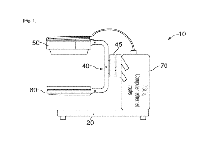
[0053] [Fig.11 shows an example x-ray imaging apparatus 10
comprising a base 20, a
control box 70 and a "U" shaped arm 30 supported on the control box 70 by an
ad-
justable arm 45. A pivot 40 arranged between the adjustable arm 45 and the U-
shaped
arm 30 allows the latter to rotate about a horizontal axis.
[0054] On the upper arm an x-ray emitter 50 is arranged. On the
lower arm a detector 60 is
arranged. The x-ray emitter 50 and detector 60 face each other and are spaced
apart
such that a subject may be inserted in between for imaging.
[0055] The control box 20 includes power supply units, a processor
(such as a computer)
and communication means such as an ethernet router.
[0056] [Fig.21 shows another example x-ray imaging apparatus 110
comprising a base 170,
in which the control box is provided and a "U" shaped arm 130 supported on the
base
170 by an adjustable arm 180. A pivot 140 arranged between the adjustable arm
180
and the U-shaped arm 330 allows the latter to rotate about a horizontal axis.
[0057] On the upper arm an x-ray emitter 150 is arranged comprising
a high voltage
generator, a monolith and a control board. On the lower arm a detector 160 is
arranged.
The x-ray emitter 150 and detector 160 face each other and are spaced apart
such that a
subject may be inserted in between for imaging. A hand 174 is shown in
position for
imaging thereof.
[0058] [Fig.3] shows another example x-ray imaging apparatus 210
comprising a base 220
including wheels for movement thereof, a control box 270 on the base, and a
"U"
6
CA 03215530 2023- 10- 13
WO 2022/185172
PCT/IB2022/051687
shaped arm 230 supported on by an adjustable arm 245 which is itself attached
to a
support 280 which is vertically mounted on the base 220. A pivot 240 arranged
between the adjustable arm 245 and the U-shaped arm 330 allows the latter to
rotate
about a horizontal axis.
[0059] On the upper arm an x-ray emitter 250 is arranged. On the
lower arm a detector 260
is arranged. The x-ray emitter 250 and detector 260 face each other and arc
spaced
apart such that a subject may be inserted in between for imaging.
[0060] Figures 4, 5 and 6 show x-ray imaging apparatus 10, 110 210
of the type shown in
Figures 1 to 3 being used with a patient to image their ankle 290, hand 291
and foot
292 respectively.
[0061] [Fig.71 shows a schematic side view of an x-ray imaging
apparatus 310 including a
base 320, a control box 370. a U-shaped arm 330 pivotally connected to the
control
box by a pivot 340. The upper arm 330 includes an x-ray emitter 350 comprising
a
high voltage generator and a control board. The lower arm includes a detector
360. The
control box 370 comprises a processor, power supplies and other components
necessary for the operation of the apparatus.
[0062] [Fig.81 shows an exploded view of part of an x-ray emitter
450 comprising an anode
450, a guard ring 452, an emitter array 453 and a cathode 454. The emitter
array 453
comprises a two-dimensional array of more than fifty emitters in an organised
pattern.
[0063] [Fig.91 depicts in schematic foina 500 the main components
necessary to put the
apparatus into operation. The emitter 550 is seen to include an outer
shielding 558
within which are arranged the4 coils and yoke 551, the x-ray source 552, the
control
board 554, and the high voltage generator 553. An acquisition control board
555
controls the emitter in conjunction with the detector 560 to ensure the
acquisition of
sufficient number of images using different patterns of emitters such that 3D
to-
mosynthesis images are displayable on the imaging work station 562. A control
panel
563 provides a user interface. A power supply 561 is also provided.
7
CA 03215530 2023- 10- 13