Note: Descriptions are shown in the official language in which they were submitted.
Layered Composite Comprising a Fire-Retardant Composite Material
The invention relates to a layered composite comprising multiple material
layers including a fire
protection layer made of a composite material. The layered composite can be
provided as a
panel structure or a two-dimensionally or three-dimensionally curved shell
structure. The
layered composite can in particular be a lightweight vehicle structure. The
layered composite
can be used as a lightweight structure for land vehicles, watercraft and
aircraft and also for
spacecraft. It is preferably used in commercial vehicles, rail vehicles,
airplanes and in boat and
ship building. The layered composite is suitable for use as an exterior
structure and an interior
structure of a vehicle. It can advantageously form a front mask of a vehicle
or a floor structure of
a vehicle, for example a floor panel, or a vehicle tank or a sub-region of a
vehicle tank, for
example an airplane tank. Partition walls and bulkheads are other example
applications.
In weight-optimized lightweight construction, it is increasingly necessary to
counter the risk of
fire, wherein the requirement for sufficient fire protection is in opposition
to the constant demand
for weight reduction. Application-specific provisions with regard to fire
protection have to be met,
for example DIN ISO 45545 for rail vehicles or the IMO 2010 FTP code and/or
the International
Convention for the Safety of Life at Sea (SOLAS) for maritime applications and
their
implementation in national regulations.
Static and/or dynamic mechanical requirements, for example in terms of
strength, typically result
in a laminate plan which describes the individual layers or plies of the
layered composite of the
respective lightweight structure. The layered composite typically comprises a
base foam core
.. and fiber material cover layers. The foam core and cover layers are
impregnated with a fire
protection resin. This laminate structure is usually coated with a fire
protection coating, a so-
called intumescent layer, which forms an insulating layer. When exposed to
heat, the
intumescent layer foams and forms a lightweight insulation layer as a heat
barrier. Graphite
which expands in the course of this process, for example so-called exfoliated
graphite, releases
gases when exposed to heat and forms an ashing, carbonaceous insulating layer
when
1
Date Recue/Date Received 2023-12-15
combusted. The insulating layer hinders the supply of oxygen and therefore the
spread of
flames into the layered composite.
In view of these high requirements, the fire-retardant properties are in many
cases not met
because the insulation effect of the intumescent layer is not sufficient and
the thermal
conductivity of the resin in the layered composite is too high. This leads to
impermissible spread
of flames and the layered composite catching fire. In practice, therefore,
other fiber material
cover layers impregnated with fire protection resin are added in addition to
the cover layers
required for strength. Due to its greater mass, this many-layered structure
prevents heat from
quickly penetrating into the core of the lightweight structure and thus
prevents the flammable
component parts from catching fire. It is however a problem of the additional
cover layers that
they lead to a significant increase in weight. The respective structure then
meets the fire
protection requirements, but no longer meets the weight requirements made of
the original
lightweight component. Conventional fire protection not only increases the
weight but, by
association, also the price of the structure.
It is an object of the invention to provide a layered composite which affords
good fire protection
while still exhibiting a low specific weight which is suitable for lightweight
construction.
The subject of the invention is a layered composite which comprises a foam
core made of a
plastic foam, a first cover layer and a second cover layer between which the
foam core is
arranged, and a plastic resin which fills the intermediate spaces between the
cover layers in the
region of the foam core and holds the cover layers and the foam core together.
The foam core
can be structured such that it is two-dimensionally or preferably three-
dimensionally deformable.
The foam core can then exhibit foam material islands arranged next to each
other in both
surface directions in a plan view, wherein any two adjacent foam material
islands are separated
from each other by an interjacent attenuation region and connected to each
other by a foam
material bridge each, such that they can be moved relative to each other and
the foam core as a
whole can be two-dimensionally or three-dimensionally deformed by shifting
foam material
islands relative to each other. The attenuation regions can in particular be
breaches between
the material islands which are bridged by the connecting material bridges.
2
Date Recue/Date Received 2023-12-15
The first cover layer and/or the second cover layer is/are (each) a fiber
material layer containing
reinforcement fibers embedded in plastic. The reinforcement fibers can
advantageously form a
textile sheet structure, for example a fiber fabric or a fiber scrim or a
knitted fabric or a
non-woven fabric. The respective fiber material layer can exhibit multiple
textile sheet structures
next to each other and/or in particular in multiple plies one above the other.
The layered composite also comprises a fire protection layer made of a
composite material. The
fire protection layer is provided on a side of the fiber material layer facing
away from the foam
core. If the first cover layer and second cover layer are each a fiber
material layer, a fire
protection layer made of the composite material is provided on the side,
facing away from the
foam core, of at least one of the fiber material layers. The fire protection
layer can be provided
directly on the side of the fiber material layer facing away from the foam
core, i.e. it can
immediately follow the fiber material layer in the layered composite. It is
however also possible
.. to arrange an intumescent layer as an intermediate layer between the fire
protection layer and
the fiber material layer below it, wherein said intermediate layer can
immediately follow the fiber
material layer and/or the fire protection layer can immediately follow the
intermediate layer.
In accordance with the invention, the composite material and accordingly the
fire protection
layer consisting of it contains hollow micro-bodies made of glass or ceramics
in a plastic
material. The hollow micro-bodies define cavities in the polymer phase, such
that the composite
material exhibits a lower specific density than the plastic material of the
composite material. This
provides a fire protection layer having a low density and accordingly a low
specific weight.
In advantageous embodiments, the composite material and therefore the fire
protection layer
exhibits a density of at most 0.8 g/ccm (grams per cubic centimeter). More
preferably, the
composite material has a density of at most 0.6 g/ccm.
Where densities are specified, they relate to a pressure of 1.01325 bars and a
temperature of
20 C (laboratory conditions).
3
Date Recue/Date Received 2023-12-15
The plastic material of the composite material and therefore fire protection
layer can be solely a
polymer phase, with no additives, or a polymer phase provided with filler
material and/or
functional additives. The polymer phase of the composite material can be
formed from a single
polymer or multiple different polymers including copolymers and polymer
blends. This polymer
phase has a density of preferably at most 1.5 g/ccm or at most 1.4 g/ccm or
more preferably at
most 1.3 g/ccm. The polymer phase can conversely have a density of at least
0.7 g/ccm or at
least 0.9 g/ccm.
The polymer phase can be provided with one or more different fire protection
additives. In
advantageous embodiments, the respective fire protection additive is selected
according to its
type and only added in a proportion by mass such that the upper limits
mentioned with respect
to the polymer phase also apply to the provided plastic material of the
composite material, i.e.
the provided plastic material including the fire protection additive and
preferably also including
any other additives has a density of at most 1.5 g/ccm or at most 1.4 g/ccm or
more preferably
at most 1.3 g/ccm.
The hollow micro-bodies can in particular be hollow spheres.
The hollow micro-bodies preferably have a density of at most 0.4 g/ccm or at
most 0.3 g/ccm.
Even more preferably, they have a density of at most 0.2 g/ccm. Such hollow
micro-bodies are
for example available from 3M Corp. (Saint Paul, Minnesota, USA). The hollow
glass spheres
K1, K11, K15, K20, K2OHS, K25, K37, A16/500, A20/1000, H20/1000, S15 and S22
by 3M
Corp. having average particle densities of between 0.10 g/ccm and 0.27 g/ccm
are thus for
example suitable as the hollow micro-bodies of the fire-retardant composite
material.
It is desirable for the micro-hollow bodies to be pressure-resistant at
pressures above 15 bars,
preferably above 20 bars, and/or heat-resistant at ambient temperatures above
500 C,
preferably above 700 C.
A proportion by mass of at least 80% of the hollow micro-bodies per unit
volume of the fire
protection layer can exhibit a size of at most 120 pm (micrometers) or at most
110 pm or at
4
Date Recue/Date Received 2023-12-15
most 100 pm. If, as is preferred, the hollow micro-bodies are hollow micro-
spheres, this means
that 80% of the mass of the hollow micro-bodies per unit volume of the fire
protection layer
exhibit an outer diameter of at most 120 pm or at most 110 pm or at most 100
pm. If the hollow
micro-bodies are not spheres, but rather for example hollow bodies which are
elongated along a
main axis, the upper limits for the size apply to the respectively largest
outer extent of the hollow
micro-bodies. Preferably, at least 90% by mass of the hollow micro-bodies per
unit volume of
the fire protection layer exhibit a size of at most 120 pm or at most 110 pm
or at most 100 pm.
Conversely, it is advantageous for a proportion by mass of the hollow micro-
bodies of at least
80% to exhibit a size, for example a spherical diameter, of at least 20 pm or
at least 30 pm. In
preferred embodiments, the lower limit of 30 pm and in particular the lower
limit of 20 pm
applies to at least 90% by mass of the hollow micro-bodies. This percentage
also relates to the
overall mass of the hollow micro-bodies per unit volume of the fire protection
layer.
It is conducive to lightweight construction for the proportion by volume of
the hollow micro-
bodies of the composite material to be at least as large as the proportion by
volume of the
plastic material of the composite material. The proportion by volume of the
hollow micro-bodies
can be at least 1.5 times as large or in particular at least twice as large as
the proportion by
volume of the plastic material. At least 50% by volume or at least 60% by
volume or more
preferably at least 70% by volume of the composite material or fire protection
layer can consist
of the hollow micro-bodies.
In the interests of lightweight construction, a resin material which has a
density of at most 1.5
g/ccm or at most 1.3 g/ccm is used in advantageous embodiments as the plastic
resin which
holds the foam core and the cover layers together. The plastic resin can in
particular be a
duromer or a vitrimer or can contain a combination of the two.
It is advantageous for the composite material to have a lower density than the
plastic resin
which holds the foam core and the cover layers together. If the polymer phase
of the composite
material does not itself already exhibit a lower density than said plastic
resin, the lower density
of the composite material is achieved at least by the hollow micro-bodies.
5
Date Recue/Date Received 2023-12-15
One function of the foam core is to keep the first and second cover layers
spaced from each
other. The plastic foam which forms the foam core can have a very low density
of at most 0.4
g/ccm or even only 0.2 g/ccm at most.
Due to the high specific thermal resistance of the composite material,
effective fire protection is
already achieved by a fire protection layer which is at most 2 mm
(millimeters) or at most 1.5
mm thick. This also benefits a lightweight construction. Sufficient fire
protection can also in
particular be achieved even at such small protective layer thicknesses if at
least 80% by mass
or at least 90% by mass of the hollow micro-bodies are within the size range
mentioned, i.e.
between 20 pm and 120 pm or between 20 pm and 100 pm and more preferably
between 20
pm and 100 pm. Conversely, it is advantageous for the fire protection layer to
have a thickness
of at least 0.6 mm or at least 1 mm.
The thermal conductivity coefficient A of the composite material of the fire
protection layer is
advantageously at most half or more preferably at most a third of the thermal
conductivity
coefficient exhibited by typical composite materials of fiber material cover
layers. In
advantageous embodiments, the thermal conductivity coefficient A of the
composite material of
the fire protection layer is less than 0.6 W/(m-K) or less than 0.5 W/(m-K)
and preferably less
than 0.3 W/(m-K) or less than 0.2 W/(m-K). A thermal conductivity coefficient
A in the range of
0.1 W/(m-K) or 0.15 W/(m-K) to at most 0.5 W/(m-K) is preferred.
The proportion by volume of the plastic material of the composite material can
be reduced to a
minimum required for the fire protection layer to hold together. The hollow
micro-bodies can
advantageously be provided as the tightest packing, for example the tightest
spherical packing,
in the fire protection layer. They can directly abut each other. In
advantageous embodiments,
the plastic material fills only the inevitable cavities between the adjacent
hollow micro-bodies.
The polymer phase of the composite material can in particular contain an epoxy
resin and/or a
vinyl ester resin and/or a saturated polyester resin and/or an epoxy vitrimer
and/or a polyphenol
resin or can be formed by one of these polymers or by a mixture of two or more
of these
polymers. Epoxy vitrimers, in particular bio-based epoxy vitrimers, and bio-
based polyphenol
6
Date Recue/Date Received 2023-12-15
resins, for example furan resins, are particularly suitable. The polymer phase
of the composite
material can also contain polymer components which differ in terms of their
class of plastics, for
example a duromeric and a plastomeric component, a duromeric and a vitrimeric
component, a
plastomeric and a vitrimeric component or a combination of all three different
components,
wherein at least one of the components can also be a bio-based polymer
material, for example
a polyphenol component or epoxy vitrimer component.
The composite material of the fire protection layer can be provided with one
or more different
fire protection additives in addition to the hollow micro-bodies. Possible
fire protection additives
include in particular phosphoric additives such as for example polyphosphates
and/or
ammonium phosphates and/or ammonium polyphosphates and/or melamine and/or
melamine
phosphates and/or melamine polyphosphates and/or DOPO phosphoramidates. If the
polymer
phase of the composite material is provided with one or more additional fire
protection additives,
the proportion of the one or more different fire protection additives
constitutes at least 0.1% by
mass and at most 20% by mass of the plastic material of the composite material
as a whole,
wherein the plastic material is understood to be the polymer phase and the
optional additives
together. Due to the hollow micro-bodies made of glass or fire-retardant
ceramics, however,
additional fire protection additives are not required and are also not
provided in advantageous
embodiments or can at least be reduced to a comparatively low level. This
benefits the
lightweight construction.
As already mentioned, the layered composite can additionally exhibit an
intumescent layer as a
gelcoat cover layer between the fire protection layer and the fiber material
layer which is closest
to the foam core, in order to generate additional protection against fire.
Instead or additionally,
.. an intumescent layer in the form of a gelcoat cover layer can be provided
on a side of the fire
protection layer facing away from the foam core, in order to generate
additional fire protection.
The composite material is suitable not only for forming a fire protection
layer outside the core
layers, i.e. the foam core and the first and second cover layers, but also for
lining the foam core.
In this function, the fire-retardant composite material can fill recesses on
the outer surface of the
foam core, for example open pores and/or perforations, and/or other cavities
which are optional
7
Date Recue/Date Received 2023-12-15
in the region of the foam core, in order to reduce the resin absorption of the
foam core and/or to
protect the foam core from fire. Plastic foams exhibit open pores which become
larger as the
density decreases, above all in regions in which the foam core has been
subsequently
machined, for example in regions in which the foam core has been structured by
means of a
separating process such as for example cutting and/or sawing. During
impregnation, the open
pores are filled with the plastic resin of the inner resin matrix which
connects the first and
second cover layers, thus increasing the weight of the foam core or core
composite consisting
of the foam core and the first and second cover layers. The weight of the
layered composite can
be further reduced by covering or lining at least regions of the outside of
the foam core with a
surface layer made of the composite material which exhibits a lower density
than the plastic
resin of the inner resin matrix, not least because of its hollow micro-bodies.
Sealing cavities in the foam core with the composite material is not only
advantageous in
combination with the fire protection layer formed outside the core composite,
but also separately
helps to improve fire protection. Another advantageous layered composite is
therefore one
which exhibits Features 1.1 to 1.3 but not 1.4 and 1.5, in which at least
regions of the foam core
are instead lined with the composite material disclosed here, such that the
composite material
seals open pores in the plastic foam on the outer surface of the foam core,
thereby preventing
plastic resin of the inner resin matrix from penetrating into the foam core
during impregnation, or
at least reducing the amount of plastic resin entering.
The plastic material of the fire protection layer can be mixed with metal
oxide particles, for
example zinc oxide particles, in order to provide protection against
electromagnetic interference
pulses. If the plastic material contains metal oxide particles, they are at
least 20 nm
(nanometers) and at most 250 nm in size. A layered composite comprising a fire
protection layer
provided with these particles can for example form a wall structure of a
housing for electronic
components or wall structures of spaces for keeping electromagnetic
interference pulses away
from electronic devices arranged in said spaces.
.. Additionally or for the purpose of weight optimization, the hollow micro-
bodies or at least some
of the hollow micro-bodies of the composite material can be coated with metal,
instead of the
8
Date Recue/Date Received 2023-12-15
metal oxide particles, in order to obtain said protection against
electromagnetic interference
pulses in addition to fire protection. If hollow micro-bodies made of glass
are used, the
composite material and consequently the layered composite are suitable for
manufacturing
lightweight structures for shielding electronic transmitting and/or receiving
systems, while
protecting against catching fire, even without any additional measures such as
for example a
metal coating and/or metal oxide additives, due to the good dielectric
properties of such hollow
micro-bodies.
The layered composite can exhibit one or more other fire protection layer(s)
on a side of the fire
protection layer facing away from the foam core, in order to further improve
fire protection while
maintaining a low weight. The two or more fire protection layers in total can
differ from the fire
protection layer disclosed here in relation to their layer thickness and/or
plastic material and/or
hollow micro-bodies and/or mixing ratio. Conversely, the statements made with
respect to the
fire protection layer and its composite material apply similarly to any other
fire protection layer.
In the interests of keeping the weight as low as possible, it is advantageous
for the fire
protection function to be concentrated on the fire protection layer and/or on
lining cavities on the
surface of the foam core with the composite material. Additionally, however,
the plastic foam of
the foam core and/or the plastic resin which holds the foam core and the cover
layers together
can in principle also be provided with one or more different fire protection
additives.
The composite material disclosed in connection with the fire protection layer
is also ideally
suitable for use as a highly filled fire protection filler for filling
cavities between lightweight
structures arranged next to each other or one on top of the other or for
filling cavities in a
lightweight structure. The composite material can then for example be used to
fill joins or to line
the fillet region of two lightweight structures which together form an
overlapping join, i.e. which
lie one on top of the other in an overlap, such as a fillet seam, wherein the
composite material
can be used as a filler, in particular in combination with lightweight
structures which exhibit a
layered composite in accordance with the invention, in order to close a gap in
fire protection
which might otherwise remain between adjacent lightweight structures or on a
lightweight
structure. The composite material is therefore also advantageous as such, i.e.
as a filler or raw
9
Date Recue/Date Received 2023-12-15
material for applying to panel-shaped or shell-shaped structures, in
particular lightweight
structures. Where features of the fire-retardant composite material are
disclosed on the basis of
the layered composite in accordance with the invention, the relevant
statements made also
apply to the composite material as such, as an initial raw material for
refining lightweight
structures and/or as a filler.
Features of the invention are also described in the aspects formulated below.
The aspects are
formulated in the manner of claims and can substitute for them. Features
disclosed in the aspects
can also supplement and/or qualify the claims, indicate alternatives with
respect to individual
features and/or broaden claim features. Bracketed reference signs relate to
example
embodiments of the invention illustrated below in figures. They do not
restrict the features
described in the aspects to their literal sense as such, but do conversely
indicate preferred ways
of implementing the respective feature.
Aspect 1. A layered composite, comprising:
1.1 a foam core (1) made of a plastic foam;
1.2 a first cover layer (7) and a second cover layer (8), between which the
foam core (1)
is arranged, wherein at least one of the cover layers (7, 8) is a fiber
material layer (8)
containing reinforcement fibers embedded in plastic, preferably in the form of
one or
more plies of a textile sheet structure;
1.3 a plastic resin (5) which fills intermediate spaces between the cover
layers (7, 8) in
and around the foam core (1) and holds the cover layers (7, 8) and the foam
core (1)
together; and
1.4 a fire protection layer (10) made of a composite material (11, 12) on a
side of the fiber
material layer (8) facing away from the foam core (1) and/or
1.5 a composite material (11, 12) which lines at least regions of the foam
core (1), such
that the composite material (11, 12) seals open pores in the plastic foam on
the outer
surface of the foam core (1),
1.6 wherein the composite material (11, 12) contains hollow micro-bodies
(12) made of
ceramics or glass in a plastic material (11).
Date Recue/Date Received 2023-12-15
Aspect 2. The layered composite according to the preceding aspect,
wherein the composite
material (11, 12) has a density of at most 0.8 g/ccm or at most 0.6 g/ccm.
Aspect 3. The layered composite according to any one of the preceding
aspects, wherein at
least 80% by mass of the plastic material (11) of the composite material (10)
consists of a
polymer phase having a density of at most 1.5 g/ccm or at most 1.3 g/ccm.
Aspect 4. The layered composite according to the preceding aspect,
wherein the polymer
phase (11) of the composite material (10) has a density of at least 0.7 g/ccm
or at least
0.9 g/ccm.
Aspect 5. The layered composite according to any one of the preceding
aspects, wherein
the hollow micro-bodies (12) have a density of at most 0.4 g/ccm or at most
0.3 g/ccm.
Aspect 6. The layered composite according to any one of the preceding
aspects, wherein a
proportion by mass of at least 80% of the hollow micro-bodies (12) exhibits an
outer extent
of at most 120 pm or at most 100 pm.
Aspect 7. The layered composite according to any one of the preceding
aspects, wherein a
proportion by mass of at least 80% of the hollow micro-bodies (12) exhibits an
outer extent
of at least 20 pm or at least 30 pm.
Aspect 8. The layered composite according to any one of the preceding
aspects, wherein a
proportion by mass of at least 80% of the hollow micro-bodies (12) exhibits a
greatest
outer extent of at most 120 pm and at least 20 pm.
Aspect 9. The layered composite according to any one of the preceding
aspects, wherein
the proportion by volume of the hollow micro-bodies (12) of the composite
material (10) is
at least as large as the proportion by volume of the plastic material (11) of
the composite
material (10).
11
Date Recue/Date Received 2023-12-15
Aspect 10. The layered composite according to any one of the preceding
aspects, wherein
the proportion by volume of the hollow micro-bodies (12) of the composite
material (10) is
larger, preferably at least 1.5 times or at least twice as large as the
proportion by volume
of the plastic material (11) of the composite material (11, 12).
Aspect 11. The layered composite according to any one of the preceding
aspects, wherein
the composite material (11, 12) has a lower density than the plastic resin (5)
which holds
the foam core (1) and the cover layers (7, 8) together.
Aspect 12. The layered composite according to any one of the preceding
aspects, wherein
the plastic resin (5) which holds the foam core (1) and the fiber material
layers (7, 8)
together has a density of at most 1.5 g/ccm or at most 1.3 g/ccm.
Aspect 13. The layered composite according to any one of the preceding
aspects, wherein
the plastic foam of the foam core (1) has a density of at most 0.4 g/ccm or at
most 0.2
g/ccm.
Aspect 14. The layered composite according to any one of the preceding
aspects, wherein
the fire protection layer (10) has a thickness of at most 2 mm or at most 1.5
mm.
Aspect 15. The layered composite according to any one of the preceding
aspects, wherein
the fire protection layer (10) has a thickness of at least 0.6 mm or at least
1 mm.
Aspect 16. The layered composite according to any one of the preceding
aspects, wherein
the hollow micro-bodies (12) are hollow spheres.
Aspect 17. The layered composite according to any one of the preceding
aspects, wherein at
least 80% by mass of the plastic material (11) of the composite material (10)
consists of a
polymer phase which is or contains an epoxy resin or a vinyl ester resin or a
saturated
polyester resin or an unsaturated polyester resin or a bio-based polyphenol
resin, such as
12
Date Recue/Date Received 2023-12-15
for example furan resin, or an epoxy vitrimer or a mixture of two or more of
these
polymers.
Aspect 18. The layered composite according to any one of the preceding
aspects, wherein at
least 80% by mass of the plastic material (11) of the composite material (10)
consists of a
polymer phase which contains or is a bio-based polymer material, preferably a
bio-based
polyphenol resin and/or a bio-based epoxy vitrimer.
Aspect 19. The layered composite according to any one of the preceding
aspects, wherein at
least 80% by mass of the plastic material (11) of the composite material (10)
consists of a
polymer phase which contains at least two different polymer components
selected from a
duromeric component, a plastomeric component and a vitrimeric component,
wherein at
least one of the components is preferably a bio-based polymer material, for
example a
polyphenol component or epoxy vitrimer component.
Aspect 20. The layered composite according to any one of the preceding
aspects, wherein
the plastic material (11) of the composite material (10) is provided with one
or more
different fire protection additives, for example polyphosphate and/or ammonium
phosphate and/or ammonium polyphosphate and/or melamine and/or melamine
phosphate and/or melamine polyphosphate and/or DOPO phosphonamidate.
Aspect 21. The layered composite according to any one of the preceding
aspects, wherein a
proportion by mass of at least 0.1% and at most 20% of the plastic material
(11) of the
composite material (10), relative to the mass of the plastic material (11) of
the fire
protection layer (10), contains fire protection additives.
Aspect 22. The layered composite according to any one of the preceding
aspects, wherein
the layered composite additionally exhibits an intumescent layer (15) as a
gelcoat cover
layer between the fiber material layer (8) and the fire protection layer (10)
and/or on a side
of the fire protection layer (10) facing away from the fiber material layer
(8), in order to
provide additional protection against fire.
13
Date Recue/Date Received 2023-12-15
Aspect 23. The layered composite according to any one of the preceding
aspects, wherein
the composite material (11, 12) fills recesses on the outer surface of the
foam core (1), for
example open pores and/or perforations, and/or intermediate spaces in the foam
core (1),
in order to reduce the resin absorption of the foam core (1) and/or to protect
the foam core
(1) from fire.
Aspect 24. The layered composite according to any one of the preceding
aspects,
comprising one or more intermediate layers made of solid-material micro-bodies
which
each have a greatest extent of 0.5 to 1.5 mm, in order to prevent or impede
projectiles
and/or splinters from penetrating in.
Aspect 25. The layered composite according to the preceding aspect,
wherein the
solid-material micro-bodies are spheres and/or the solid material is solid
ceramics.
Aspect 26. The layered composite according to any one of the preceding
aspects, wherein
the plastic material (11) of the composite material (10) is mixed with metal
oxide particles
(13), for example zinc oxide particles (13), in order to provide protection
against
electromagnetic interference pulses, wherein the metal oxide particles (13)
are at least 20
nm and at most 250 rim in size.
Aspect 27. The layered composite according to any one of the preceding
aspects, wherein at
least some of the hollow micro-bodies (12) of the composite material (10) are
coated with
metal in order to obtain protection against electromagnetic interference
pulses in addition
to fire protection.
Aspect 28. The layered composite according to any one of the preceding
aspects, wherein
the plastic foam of the foam core (1) and/or the plastic resin (5) is/are
provided with one or
more different fire protection additives.
14
Date Recue/Date Received 2023-12-15
Aspect 29. The layered composite according to any one of the preceding
aspects, wherein
the fiber material layer (8) contains at least some of the reinforcement
fibers as fiber fabric
and/or fiber scrim and/or knitted fabric in one or more plies.
Aspect 30. The layered composite according to any one of the preceding
aspects, wherein at
least some of the reinforcement fibers of the fiber material layer (8) are
glass fibers and/or
carbon fibers and/or basalt fibers.
Aspect 31. A composite material (11, 12) which contains hollow micro-
bodies (12) made of
glass or ceramics in a plastic material (11) and which is used as a highly
filled fire
protection filler, preferably in combination with the layered composite
according to any one
of the preceding aspects.
Example embodiments of the invention are described below on the basis of
figures. Features
disclosed by the example embodiments, each individually and in any combination
of features,
advantageously develop the subject matter of the claims and the embodiments
described above
as well as the aspects. There is shown:
Figure 1 a layered composite in accordance with the invention in an
isometric view;
Figure 2 the layered composite in a cross-section;
Figure 3 a region of a fire protection layer of the layered composite in a
schematic
representation; and
Figure 4 a region of a modified fire protection layer in a schematic
representation.
Figure 1 shows a layered composite in accordance with the invention in the
form of a
panel-shaped semi-finished product. The layered composite comprises a foam
core 1 made of a
plastic foam, for example foamed polyethylene terephthalate (PET). The foam
core 1 is
structured such that it is three-dimensionally deformable. The foam core 1 is
a sheet structure
having a structure which allows the foam core 1 to be deformed around axes
located in the
surface, such that the foam core 1 can for example be shaped into a tube or a
shell which is
curved around different axes, without any appreciable mechanical resistance.
The foam core 1
Date Recue/Date Received 2023-12-15
is sub-divided into a multitude of material islands 2 which are arranged next
to each other in the
plan view and delineated from each other by material attenuations. Connecting
bridges 3 remain
in the region of the material attenuations, which can in particular be formed
as breaches,
wherein each of the material islands 2 is connected to all of the immediately
adjacent material
islands 2 by at least one and preferably only one connecting bridge 3 in each
case.
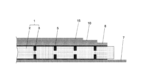
The foam core 1 is arranged between a first cover layer 7 and a second cover
layer 8 which
cover the foam core 1 on a lower side and an upper side.
.. Figure 2 shows the layered composite in a section which is orthogonal with
respect to the cover
layers 7 and 8. The section extends through the material islands 2 and the
connecting bridges 3
of the foam core 1. The cavities which remain between the cover layers 7 and 8
in the region of
the foam core 1 and delineate respectively adjacent material islands 2 from
each other but are
bridged by the connecting bridges 3 are filled with a plastic resin 5. The
plastic resin 5 also
covers at least regions of the lower side and the upper side of the foam core
1, where it forms a
thin resin layer in the transition from the foam core 1 to the respective
cover layer 7 or 8. The
plastic resin 5 connects the cover layers 7 and 8 in a material bond, wherein
it fills or permeates
the foam core 1 in the region of the cavities or otherwise configured material
attenuations
(Figure 1). The plastic resin 5 forms a resin matrix which encloses the
material islands 2
laterally and preferably also on their lower side and upper side.
The foam core 1 forms a base sandwich structure with the cover layers 7 and 8
and the
connecting plastic resin 5. The base sandwich structure 1, 5, 7, 8 can itself
form the mechanical
framework for a lightweight structure, for example a lightweight panel or a
lightweight shell
structure, and in this function can absorb the static and/or dynamic loads of
the lightweight
structure.
As shown in Figures 1 and 2, the layered composite exhibits a fire protection
layer 10 on a side
of the cover layer 8 facing away from the foam core 1. The fire protection
layer 10 consists of a
composite material. The composite material can be applied directly to the
cover layer 8.
Alternatively, it is also possible to firstly apply an expediently thin
intermediate layer, for
16
Date Recue/Date Received 2023-12-15
example a gelcoat layer, to the cover layer 8 and to apply the composite
material to this
intermediate layer. The composite material can for example be sputtered,
sprayed or applied by
means of a roller onto the cover layer 8 or an optional intermediate layer.
Figures 1 and 2 indicate how the layered composite can exhibit an intumescent
layer 15 on the
side of the fire protection layer 10 facing away from the foam core 1, further
outwards as viewed
from the foam core 1. The intumescent layer 15 can be provided in addition to
or instead of the
optional intermediate layer. It can in particular be a gelcoat layer. The
intumescent layer 15
and/or the optional intermediate layer can for example serve to improve fire
protection and/or as
mechanical protection for the fire protection layer 10 and/or the base
sandwich structure 1, 5, 7,
8 below it.
Figure 3 shows a small region of the fire protection layer 10 in a significant
enlargement. The
fire protection layer 10 consists of the composite material which consists of
a plastic material 11
as a support or matrix and hollow micro-bodies 12 made of glass or a ceramic
material
distributed in the plastic material 11. Although the hollow micro-bodies 12
can in principle exhibit
any shape, for example an elongated oval shape, they are expediently hollow
micro-spheres.
Suitable hollow micro-spheres made of glass are for example available from 3M
Corporation
(Minnesota, USA).
At least 80% by mass or at least 90% by mass of the hollow micro-bodies 12
have an outer
extent of at most 120 pm. More preferably, at least 80% by mass or at least
90% by mass have
an outer extent of at most 110 pm or at most 100 pm. It is advantageous for at
least 80% by
mass or at least 90% by mass of the hollow micro-bodies 12 to have an outer
extent of at least
20 pm. More preferably, at least 80% by mass of the hollow micro-bodies 12
have a greatest
outer extent of at least 30 pm. If the hollow micro-bodies 12 are hollow micro-
spheres, as in the
example embodiment, the "outer extent" is the outer diameter of the hollow
micro-spheres. By
selecting the hollow micro-bodies 12 from the size range mentioned, a
composite material
having a low density on the one hand and a sufficient compressive strength of
the hollow
micro-bodies 12 on the other is obtained.
17
Date Recue/Date Received 2023-12-15
The plastic material 11 is at least substantially a polymer phase, wherein the
polymer phase can
consist of a single polymer or a combination of multiple polymers, including
copolymers and
polymer blends. The plastic material 11 can contain additives, for example
mere fillers and/or
functional additives, in particular fire protection additives and/or for
example additives for shock
absorption or another mechanical property and/or for improving or achieving
electromagnetic
shielding properties. The polymer phase, i.e. the solely polymeric
ingredients, constitute at least
80% by mass or at least 85% by mass or at least 90% by mass of the plastic
material 11. The
one or more different additives provide the optionally remaining proportion by
mass.
Figure 4 likewise shows a small region of a fire protection layer 10 made of a
modified
composite material. The modified composite material differs from the composite
material
described above in that its plastic material 11 contains metal oxide particles
13, for example
zinc oxide particles. The metal oxide particles 13 have outer dimensions in
the range of 20 nm
to 250 nm and serve to achieve or improve an electromagnetic shielding effect.
The statements
made with respect to the composite material of Figure 3 otherwise apply, such
as for example
the statements made with respect to the upper limit for the proportion by mass
of additives.
An epoxy resin having a density of between 1.17 g/ccm and 1.25 g/ccm can for
example be
used as the plastic material 11 for the fire protection layer 10. This plastic
material 11 is mixed
with hollow micro-spheres 12 having diameters in the range of 20 pm to 120 pm.
Preferably, at
least 80% by mass of the hollow micro-spheres 12 have a diameter of at most
110 pm or at
most 100 pm.
The viscosity of the plastic material 11 is set to be low enough that the
hollow micro-spheres 12
are completely wetted on their outer surfaces and densely packed once mixed,
and the
intermediate spaces remaining between the hollow micro-spheres 12 are
uniformly filled with
the plastic material 11. By selecting the material (polymer phase with
optional additive or
additives) and/or the temperature, the viscosity is also set such that the
composite material, i.e.
the mixture of the plastic material 11 and the hollow micro-spheres 12, can be
uniformly applied
by sputtering, brushing, rollering or the like.
18
Date Recue/Date Received 2023-12-15
In advantageous embodiments, the hollow micro-bodies 12 have a density of less
than 0.4
g/ccm or less than 0.3 g/ccm, preferably even less than 0.2 g/ccm. In the
mixture and also in the
finished layered composite, i.e. when the fire protection layer 10 is solid,
the fire protection layer
contains a proportion by volume of at least 60% or at least 70% of the hollow
micro-bodies
5 12, and the plastic material 11 constitutes the respectively residual
proportion by volume.
If the plastic material 11 does not contain any additives, the composite
material and therefore
the finished fire protection layer 10 will have a density of 0.74 g/ccm (0.6 =
0.4 g/ccm +
0.4 = 1.25 g/ccm) on the basis of the values mentioned for the combination
which is least
10 favorable for weight. If, by contrast, the composition is selected to
exhibit the mixing ratio and
lower densities which are more favorable for the lowest possible weight, the
composite material
or the fire protection layer 10 consisting of it has a density of 0.49 g/ccm
(0.7 = 0.2 g/ccm + 0.3 =
1.17 g/ccm). If, as is preferred, the proportion by volume of the hollow micro-
bodies 12 is
increased to over 70%, the density of the composite material then formed
decreases even
further.
If, by contrast, additives are added to the polymer phase of the plastic
material 11, for example
15% by mass of a phosphoric fire protection additive which typically exhibits
a density of at most
1.82 g/ccm, the composite material has a density of slightly more than 0.77
g/ccm (0.6 = 0.4
g/ccm + 0.4 = (0.85 = 1.25 + 0.15 = 1.82) g/ccm), i.e. still below 0.8 g/ccm.
19
Date Recue/Date Received 2023-12-15