Note: Descriptions are shown in the official language in which they were submitted.
CA 03216823 2023-10-16
WO 2022/221549 PCT/US2022/024843
Title: SINGLE USE FLEXIBLE SPARGER
[0001] The present application claims the benefit of U.S. Provisional Patent
Application No.
63/175,696, filed on April 16, 2021, the entire contents of which is
incorporated by reference
herein in its elliirety.
FIELD
[0002] Earbodiments disclosed herein relate to devices for the bioprocessing
of biological
fluids. More particularly, the devices include aeration devices for use within
a container or
vessel, such as a bioreactor, e.g., single use stirred tank bioreactors having
volumes between
50-5000 liters.
BACKGROUND
[0003] Traditionally, fluids such as biological materials have been processed
in systems that
utilize stainless steel containers or vessels. These containers are sterilized
after use so that
they can be reused. The sterilization procedures are expensive and cumbersome,
as well as
being ineffectual at times. In order to provide greater flexibility in
manufacturing and reduce
the time needed to effect a valid regeneration of the equipment, manufacturers
have begun to
utilize disposable sterilized containers and/or bioreadors such as collapsible
bags, which are
used once and subsequently disposed. An example of use of these disposable or
single-use
bags is in a system for mixing .t-wo or more ingredients, at least one of
which is liquid and the
other(s) being liquid or solid, and the bag has a mixing element or the like
for causing the
contents to mix as uniformly as possible. An example of a disposable container
is a bioreactor
or fermenter hag in which cells are either in suspension or on microcaniers
and the container
has a mixing system for circulating the liquid, gases, and in some cases the
cells within the
interior of the container.
[0004] Many conventional mixing bags, which typically range in size from three
(13) Liter to
smaller and fifty (50) liter or larger, i.e., 5000 liter, are shaped like
cylinders, with the bottom
of the bag optionally forming a cone, to mimic the shape of stainless-steel
tanks that the
disposable bags are replacing. Cylindrical shaped bioreactors allow the
contents of the bag to
be mixed in an efficient manner. Typically, the hag contains a mixer for
mixing or circulating
the contents, such as a magnetically coupled impeller contained within the bag
and a
magnetic motor outside the hag, which remotely causes the impeller to rotate.
The containers
CA 03216823 2023-10-16
WO 2022/221549 PCT/US2022/024843
also can contain one or more aeration devices, e.g., gas spargers, through
which gas bubbles
are introduced into the container contents. The contents are typically
biopharmaceutical or
other biological fluids. Such fluids typically comprise cell culture media and
adjuvants. The
containers contain gases, such as air, oxygen, carbon dioxide, nitrogen, etc.
Spargers for use
with 50-5000 liter bioreactors have air supplied through the bottom of the
bioreactor.
Because of the pressure of 50-5000 liters of fluid, spargers must have check
valves or use
high pressures .to create the back pressure necessary to prevent liquids from
back flowing into
the sparger during aeration.
[0005] Aeration of biological fluids within bioreactors is common to support
cell culture
oxygenation via sparing devices. However, the use of high gas flow rates used
to achieve
high levels of oxygenation, measured as kLa, can result in high speeds and
very small
bubbles, which can cause cell shear and induce cell death; wherein kLa is a
gas transfer
coefficient, e.g., a measurement of the capacity of the bioreactor to transfer
oxygen into the
culture. High speeds and small bubbles can result in undesirable bioprocess
product losses or
changes in product quality, yet, a high kLa is requisite to achieving high
cell density, for
example in perfusion processes. Hence distribution of gas flow can be achieved
to maximize
gas transfer to achieve a high kLa by using sparging, suitable for specific
flow requirements.
[0006] Past attempts for sparging devices include drilled hole spargers, which
were created
from a film or a mold. These devices aimed to control the bubble size and/or
the exit gas
velocity of air. However, for film spargers the flexibility of the film
material resulted in a
lack of a controlled pressure gradient across the sparger area, resulting in
lower oxygen
transfer, wider distribution of bubble sizes and leakage. Molded devices are
expensive and
bulky, may occupy significant space inside single use bioreactors, and damage
the interior of
bioreactors during transit. Another prior art flexible sparger, comprising two
film layers
lacked an even distribution of air, i.e., the air flow goes out the highest
point of the sparger
and did not distribute air to the entire area of sparger, e.g., in discrete
pockets only.
[0007] As noted above, bubble size of aerated gases is important. In
bioreactor applications,
for example, a balance exists for managing bubble number and sizes such that
mass transfer
from the gas-liquid phase or vice versa is sufficient for the process while
preventing negative
culture effects such as significant shear or foaming. Generally, smaller
bubble sizes are more
efficient in transferring as from the bubble to the liquid or biological
fluid, due to an
increased surface area. However, the smaller the bubble, the greater the
potential damage to
cells as compared to larger bubble sizes due to their similar size to cells
and their potential to
promote accumulation of foam on the liquid surface. Similarly, creating and
maintaining a
2
CA 03216823 2023-10-16
WO 2022/221549 PCT/US2022/024843
generally homogenous environment for the contents of the container, such as
cells in culture,
is also important in bioreactorlbioprocessing operations. It is undesirable to
have regions
and/or gradients, i.e., differences in mixing (pH, nutrients, and dissolved
gases), shear,
temperature, etc., within bioreactors. Some cell culture processes may require
the highest
possible mass transfer capabilities while others may require specific bubble
sizes that are
large enough so that sensitive cells are unharmed. To date, there was no
sparging device
suitable for balancing bubble sizes with shear and foam generation.
[0008] It is therefore an advance to provide a container or bioreactor, such
as a disposable or
single-use container or bioreactor for biological fluids, wherein a sparging
device(s) aid in
optimal cell culture growth performance and viability by providing sparging
devices that are
small, flexible, and can balance the competing aspects of bubble size,
shearing, foaming, air
distribution, and other bioprocessing conditions.
SUMMARY
[0009] Embodiments of a multi-layered drilled hole flexible sparger comprising
three film
layers and two mesh layers, substantially as shown in and/or described in
connection with at
least one of the figures, as set forth more completely in the claims, are
disclosed. Novel and
inventive features of the present disclosure, as well as details of exemplary
embodiments
thereof, will be more ful by understood from the following description and
drawings. Some
embodiments of the disclosure include a multi-layered flexible sparger that
has a bottom film
layer, a middle film layer, and a top film layer; a first inner mesh disposed
between the bottom
film layer and the middle film layer; a second inner mesh disposed between the
middle film
layer and the top film layer; and a port capable of delivering a gas to the
multi-layered flexible
sparger disposed between the top film layer and the bottom film layer, wherein
the middle film
layer comprises drill holes and the top film layer comprises drill holes. Some
embodiments of
the disclosure include a multi-zone, multi-layered, flexible sparger having a
bottom film layer,
a middle film layer, and a top film layer; a first inner mesh disposed between
and bonded to
the bottom film layer and the middle film layer; a second inner mesh disposed
between and
bonded to the middle film layer and the top film layer; and a port capable of
delivering a gas
to at least two sparging zones within the multi-zone, multi-layered flexible
sparger disposed
between the top film layer and the bottom film layer, wherein the middle film
layer comprises
drill holes and the top film layer comprises drill holes.
[0010] In some embodiments, the multi-layered flexible drilled hole sparger is
a single-use
sparger. Some embodiments comprise wherein the middle film layer contains a
low number
3
CA 03216823 2023-10-16
WO 2022/221549 PCT/US2022/024843
of small drilled holes that resists air flow and creates back pressure between
the middle and
bottom film layers. A middle layer having a low number, for example, between
1% and 50%
as many drilled holes and/or smaller drilled holes compared with the top
layer. In some
embodiments, the middle layer comprises between 5-25% as many holes as the top
layer. In
some embodiments, the middle layer comprises between 10-20% as many holes as
the top
layer. Also, for example, drilled holes having a diameter of between 5 and
1000 microns,
promotes back pressure and gas distribution over the middle layer. Embodiments
of the
disclosure include a middle film layer having a number and size of drilled
holes that resists air
flow and creates back pressure between the middle and bottom film layers.
Also, for example,
drilled holes having a diameter of between 5 and 1000 microns, promotes back
pressure and
gas distribution over the middle layer. The top film layer contains drilled
holes designed for a
specific exit gas velocity and bubble size. A layer of mesh exists between the
top film layer
and the middle film layer to provide support for the film and physical
separation of film layers
for air flow to distribute across the sparging area.
[0011] The top film layer contains drilled holes designed for a specific exit
gas velocity and
bubble size. A layer of mesh exists between the top film layer and the middle
film layer to
provide support for the film and physical separation of film layers for air
flow to distribute
across the sparging area. The top and middle film layers are bonded into
sections that restricts
air flow to specific areas regardless of sparger orientation. The at least
three film layers are
bonded around the perimeter of the sparger and at an area in the center of the
sparger.
Embodiments of the spargers disclosed herein demonstrate substantially equal
distribution of
the gas flow rate throughout the sparger regardless of sparger orientation.
Embodiments of the
spargers disclosed herein provide uniform bubble size independent of gas flow
rate.
Embodiments of the spargers disclosed herein advance the art because the
sparger designs
herein widen optimal performance windows, offer high kLa for increased cell
density, ease of
manufacturing, and flexibility for ease of integration within existing
bioreactors and containers.
Some embodiments include the use of multiple spargers within one bioreactor.
Some
embodiments include means for switching between spargers having differing pore
sizes and/or
kLa characteristics. Such means comprise optimizing and varying gas flow
ranges using
manifolds and control schemes controlled by microprocessor-controlled
bioreactors and mass-
flow controllers. In some embodiments, desired kLa characteristics are
achieved using the
microprocessor-controlled bioreactors and mass flow controllers and further
combined with
multiple spargers capable of producing differing bubble sizes. These advances
and others
embodied herein will become clear from the description, claims, and figures
below. Various
4
CA 03216823 2023-10-16
WO 2022/221549 PCT/US2022/024843
benefits, aspects, novel and inventive features of the present disclosure, as
well as details of
exemplary embodiments thereof, will be more fully understood from the
following description
and drawings. So, the manner in which the features disclosed herein can be
understood in
detail, more particular descriptions of the embodiments of the disclosure,
briefly summarized
above, may be had by reference to the appended drawings. it is to be noted,
however, that the
appended drawings illustrate only typical embodiments of this disclosure and
are therefore not
to be considered litniting of its scope, for the described embodiments may
admit to other
equally effective bags, biocontainers, films, and/or materials, It is also to
be understood that
elements and features of one embodiment may be found in other embodiments
without further
recitation and that, where possi.ble, identical reference numerals have been
used to indicate
comparable elements that are common to the figures. As used herein, the
singular forms "a,"
an, and the include plural referents unless the context clearly dictates
otherwise. Unless
defined otherwise, all technical and scientific terms used herein have the
same meaning as
commonly understood by one of ordinary skill in the art to which these
embodiments pertain.
BRIEF DESCRIPTIONS OF THE DRAWINGS
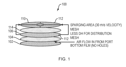
[0012] FIG. 1 depicts a side exploded perspective view of a multi-layered
flexible sparger,
according to some embodiments of the disclosure;
[0013] FIG. 2 depicts a top perspective view of a multi-layered flexible
sparger having a
flange, according to some embodiments of the disclosure;
[0014] FIG. 3 depicts a side view of the multi-layered flexible sparger of
FIG. 2, according to
some embodiments of the disclosure;
[0015] FIG. 4 depicts a top view of the multi-layered flexible sparger of FIG.
2, according to
some embodiments of the disclosure;
[0016] FIG. 5 depicts a side view of a multi-layered flexible sparger disposed
within a
bioreactor, according to some embodiments of the disclosure;
[0017] FIG. 6 depicts a close up top view of the bottom, internal surface of
the bioreactor taken
along line 6-6 in FIG. 5, showing two multi-layered flexible spargers and an
impeller,
according to some embodiments of the disclosure;
[0018] FIG. 7 depicts a top view of a multi-layered sparger having optional
locating tabs,
according to some embodiments of the disclosure;
[0019] FIG. 8A depicts a top perspective view of the multi-layered sparger of
FIG. 7;
[0020] FIG. 8B depicts a close up view of the drill holes in the top film
layer of the multi-
layered sparger of FIG. 7;
[0021] FIG. 9 depicts an exploded view of the multi-layered sparger of FIG. 7;
CA 03216823 2023-10-16
WO 2022/221549 PCT/US2022/024843
[0022] FIG. 10 depicts a top view of a multi-zone, multi-layered sparger
having optional
locating tabs, according to some embodiments of the disclosure; and
[0023] FIG. 11 depicts an exploded view of the multi-zone, multi-layered
sparger of FIG. 10.
DETAILED DESCRIPTIONS OF SOME EMBODIMENTS
[0024] The term film within the meaning of this disclosure means any flexible
material that is
capable of being fused with another flexible film, including, but not limited
to, polymeric sheet,
composites, laminates, single-layer, and/or multi-layer polymeric materials.
These films may
further comprise substrates, which may comprise plastics netting, wovens, non-
wovens, knits,
and/or metallic foils and other flexible structures and materials. The films
may comprise, for
example, a polyolefinic material, e.g., low density polyethylene, linear low-
density
polyethylene, middle density polyethylene, high density polyethylene, ultra-
high density
polyethylene, polypropylene, and other polyolefins. In some embodiments, the
flexible films
comprise a laminate film structure with a lower melting point material
internal to an external
higher melting point polymer. Also, in some embodiments, the flexible films
comprise a
laminate film structure with a lower melting point material surrounding a
higher melting point
woven, knit, or non-woven material. In some embodiments, any or all of the
bottom film,
middle film, or the top film comprise any of the films as described in WO
Publication
W02020101848A1, which is incorporated by reference in its entirety. In some
embodiments,
one or more of these films is/are substantially similar to a PUREFLEX ,
PUREFLEX PLUS
or ULTIMUS film as marketed by EMD Millipore Corporation, Burlington, MA,
USA. The
films herein discussed may be multi-layered films comprising one or more
layers of
polyethylenes, ethylene vinyl acetates, ethyl vinyl alcohol, and other
materials. In some
embodiments, any or all of the bottom film, middle film and/or top film
comprise a substrate
that is netting, wovens, non-wovens, knits, and other structures that are, for
example, made of
nylons, polyamides, and other abrasion resistant materials, wherein various
tie layers, e.g.,
polyurethanes, may be disposed between layers.
[0025] The term biocontainer is defined broadly as any flexible container or
vessel capable of
holding a fluid within an internal volume or region, and may be in the form of
a two-
dimensional, three-dimensional, and/or multi-faceted bag or bioreactor. In
some embodiments,
the biocontainer or bioreactor has a baffle incorporated therein, wherein the
baffle is capable
of disrupting a vortex within a liquid formed when a mixer, such as an
impeller, mixes the
liquid.
[0026] FIG. 1 depicts a side exploded perspective view of a multi-layered
flexible sparger 100,
according to some embodiments of the disclosure. As depicted in FIG. 1, the
multilayer
6
CA 03216823 2023-10-16
WO 2022/221549 PCT/US2022/024843
flexible sparger comprises a bottom film layer 102, having no sparging holes,
which acts as a
supporting base, and a first inner mesh 104 is disposed adjacent to the bottom
film layer 102.
The first inner mesh 104 supports the bottom film layer 102 and is a means for
distributing air
flow across a sparging area (discussed below in greater detail). In some
embodiments, the first
inner mesh 104 distributes air flow across an entire sparging area. The multi-
layered flexible
sparger further comprises a second film 106 that is disposed between the
bottom film layer 102
and a top film layer 110, the top film layer 110 having a number of drilled
holes 112. In other
words, the second film layer 106 is a middle film layer. The middle film layer
106 also
comprises a number of drilled holes 112 in a number that, in some embodiments,
is generally
fewer than the number of drilled holes 112 in the top film layer 110. In some
embodiments,
there are approximately between 10 to 50,000 drilled holes in both of the
middle film layer 106
or top film layer 110. In some exemplary embodiments, the middle film layer
106 comprises
between 20 to 200 drilled holes. In some exemplary embodiments, the top film
layer 110
comprises between 1000 to 36,000 drilled holes. It is to be understood that
the drilled holes
may be formed by any suitable process, such as the use of a porogen or various
lasers. Because
the middle film layer 106 comprises fewer drilled holes 112, the middle layer
106 is capable
of creating a back pressure of air flow. The back pressure promotes a uniform
distribution of
gas or air flow across a sparging area. In some embodiments, the flexible
sparger 100 comprises
a second inner mesh 114, which is disposed between the middle film layer 106
and the top film
layer 110. The thicknesses of the first inner mesh 104 and the second inner
mesh 114 may also
be varied to affect the sparging performance. Without intending to be limited
by theory, it is
thought that a thicker mesh may keep the bottom film layer 102 and the middle
film layer 106
further apart, resulting in better sparging performance. For example, it is
thought that a thicker
mesh promotes an even air flow distribution. Similarly, it is thought that a
thicker mesh may
keep the middle film layer 106 and the top film layer 110 further apart,
resulting in better
sparging performance. In some embodiments, the top film layer 110 comprises
drilled holes
112 designed for at one specific exit gas velocity and bubble size. It is also
thought that drilled
holes 112 in film layers provide enhanced consistency over non-woven
structures or membrane
structures within spargers, providing constant and predictable bubble sizes.
In some
embodiments, the middle 106 and top film layers 110 are bonded in sections to
restrict gas flow
to specific areas. All three film layers, i.e., the bottom film layer 102, the
middle film layer
106, and the top film layer 110 are bonded at a perimeter and at a center of
the flexible sparger.
The multi-layered flexible sparger 100 further allows vertical gas flow into a
bioreactor
regardless of the orientation in which the multilayer flexible sparger 100 is
within a bioreactor
7
CA 03216823 2023-10-16
WO 2022/221549 PCT/US2022/024843
(not shown). In other words, the gas or air flow remains uniform across the
flexible sparger
irrespective of orientation. In yet some other embodiments, the flexible
sparger 100 has no
middle film layer 106. In other words, a multi-layered flexible sparger 100
comprises a bottom
film layer 102, a top film layer 110 having drill holes 112, and a mesh 114
disposed
therebetween. In some embodiments, the drilled holes 112 in the middle film
layer 106 range
in size from 10 microns to 800 microns in diameter. In some embodiments, the
drilled holes
112 in the top film layer 110 range from 10 microns to 800 microns in
diameter. In some
embodiments, the drilled holes 112 in the top film layer 110 are less than 100
microns in
diameter. All embodiments of the flexible sparger herein comprise a port for
supplying air or
another gas into the flexible sparger. The port may be disposed on top (such
as in a center of
the top film layer) of the flexible sparger, on the bottom (such as in a
center of the bottom film
layer) of the flexible sparger, or on a side of the flexible sparger. The
flexible sparger may
comprise a substantially circular shape or, for example, a substantially
circular shape having a
flange adjacent to a circularly shaped area (e.g., a whoopie cushion). In some
embodiments,
the port supplies air or a gas to the flexible sparger via the flange.
[0027] FIG. 2 depicts a top perspective view of a flexible sparger 200 having
a flange 202,
according to some embodiments of the disclosure. The flexible sparger 200 is
substantially
circular while the flange 202 may be of any suitable shape. As depicted, the
flange 202 is
rectangularly shaped. The flange 202 comprises a port 204, which projects from
an upper
portion of the flange 202. In some embodiments, the port 204 may project from
a lower portion
of the flange 202. The port 204, when connected to a gas supply, such as air
or oxygen, delivers
air into the flexible sparger 200. In some embodiments, the port 204 comprises
a connector,
such as a barb 206 for connection with a tube (not shown), a connector, or a
sterile connector.
In some embodiments, the port 204 is connected to the middle film layer 106
and/or the top
film layer 110.
[0028] In some embodiments, the first and/or second inner mesh comprise a
woven or extruded
mesh, embossed and/or apertured film, or a membrane having a low open area
(areas open to
gas flow) as a middle layer to create back pressure, such that air is
distributed through all
openings on the middle layer. In some embodiments, flow pockets are created by
means of
sealing layers of film together, wherein air or gas flow is directed to
specific areas of the
flexible sparger, achieving a substantially even distribution of gas flow
within the flexible
sparger, resulting in consistent bubble size and bubble velocity across a
surface of the flexible
sparger regardless of sparger orientation angle, gas flow rate, or a head
pressure. For example,
the flexible sparger 200 further comprises flow pockets 208. As shown, there
are eight flow
8
CA 03216823 2023-10-16
WO 2022/221549 PCT/US2022/024843
pockets 208. The flow pockets 208 are formed by bonds, such as can be made by
ultrasonic
welding, heat welding, adhesives, etc., and other methods for joining plastics
films as is known
to those in the art. In some embodiments, bonds are formed using high
frequency/radio
frequency (RF) bonding. In some embodiments, the RF bonding process is a two-
step RF
bonding process. In some embodiments, the RF bonding process is a three-step
RF bonding
process. RF welding is the placement of plastics materials between two
opposing metallic
plates. Pressure is applied to the plates, and therefore onto the plastics,
while RF waves are
sent through the plates, creating heat that fuses the plastics together. A
bond 210 is made just
inside of the perimeter of the flexible sparger 200. A central bond 212 is
made in the center,
wherein all layers are bonded together. And eight radial legs 214 projecting
from the central
bond 212 and the perimeter bond 210. The perimeter bond 210 is made through
that is inclusive
of the bottom film layer 102, the middle film layer 106, and the top film
layer 110. The flow
pockets 208 are formed by sealing the top film layer 110 and the middle film
layer 106.
Optionally, a spot bond 216 is made in each flow pocket 208 by bonding the
middle layer 106
with the second inner mesh 114.
[0029] FIG. 3 depicts an exploded side view cross-section of the multi-layered
flexible sparger
200 of FIG. 2, according to some embodiments of the disclosure. As shown, a
bottom film
layer 102, a middle film layer 106, and a top film layer 110 are present in
the multi-layered
flexible sparger 200. The port 204 is depicted as being incorporated into the
flange. The port
204 is a barb-style 206 port and comprises a shoulder 218 for attachment to
the middle film
layer 106 and the top film layer 110. Because the port 204 projects between
the middle film
layer 106 and the bottom film layer 102, air or another gas is supplied
therebetween as well.
The first inner mesh 104 and second inner mesh 114 are also shown. In some
embodiments, as
shown, the first inner mesh 104 and second inner mesh 114 are smaller than a
diameter of the
flexible sparger 200 so that bottom film layer 102, middle film layer 106 and
top film layer 110
can be bonded at the perimeter bond 210. In some embodiments, the first inner
mesh 104 and
second inner mesh 114 are essentially the same diameter and therefore become
part of the
perimeter bond 210 (not shown in FIG. 3).
[0030] FIG. 4 depicts a top view of the multi-layered flexible sparger 200 of
FIG. 2, according
to some embodiments of the disclosure. The top view depicts the multi-layered
flexible sparger
200 having the radial legs 214 in each of the eight flow pockets 208 and
around the perimeter
bond 210 of an outer border and of a central bond 212 area. The spot bonds 216
are shown,
one each for each flow pocket 208. The port 204 is shown in the flange 202. A
bond 222 is
also shown, which is between the top film layer 110 and the middle film layer
106 and
9
CA 03216823 2023-10-16
WO 2022/221549 PCT/US2022/024843
completes two of the flow pockets 208. An optional bond disposed between two
opposing
sides of the bond 222, which further supports the multi-layered flexible
sparger 100, 200 in
some embodiments.
[0031] FIG. 5 depicts a side view of a flexible sparger, such as the multi-
layered flexible
sparger 200 of FIG. 2, disposed within a bioreactor 300, according to some
embodiments of
the disclosure. Some embodiments of the disclosure comprise a bioreactor
system having a
bioreactor and a multi-layered flexible sparger 100, 200 as discussed above.
The multi-layered
flexible sparger 100, 200 may be disposed on a bottom, internal surface of the
bioreactor 300.
Also, the multi-layered flexible sparger 100, 200 may be disposed on a bottom,
internal surface
308 of the bioreactor 300 in a geometric center of the bioreactor or off-
center (as shown). In
some embodiments, the multi-layered flexible sparger 100, 200 is attached to
the bottom,
internal surface 308 of the bioreactor 300 or is free-floating within the
bioreactor 300. In some
embodiments, a plurality of multi-layered spargers 100, 200 is disposed within
the bioreactor
300. For example, between two (as shown in FIG. 6) and eight multi-layered
spargers. Any
of the bioreactors described herein, such as bioreactor 300, may have a
working volume 310
of between 50 liters and 3000 liters. In some embodiments, the working volume
310 of the
bioreactor 300 is between 200 liters and 2000 liters. As shown, the bioreactor
300 further
comprises ports 304 for delivering or removing gases or liquids from the
working volume 310.
A baffle 302 is shown. An impeller 306 for mixing liquids within the working
volume 310 is
also shown.
[0032] FIG. 6 depicts a close up top view of the bottom, internal surface 308
of the bioreactor
300 taken along line 6-6 in FIG. 5, showing two multi-layered flexible
spargers 100, 200 and
an impeller 306, according to some embodiments of the disclosure. The multi-
layered flexible
spargers 100, 200 show the drilled holed 112 and the port 204. The ports 204
can be supplied
by the ports 304, or other ports, which are outside the bioreactor 300.
[0033] FIG. 7 depicts a top view of a multi-layered sparger 400 having
optional locating tabs,
according to some embodiments of the disclosure. The multi-layered sparger 400
comprises
the radial legs 414 adjacent each of the eight flow pockets 448 and around the
perimeter bond
442 of an outer border and of a central bond 413a, 413b area. The radial legs
414 are bonded
areas. The bonds are formed within two or more of the layers of the multi-
layered sparger 400.
In some embodiments, the radial legs 414 are bonds that bond all layers of the
multi-layered
sparger 400. The multi-layered sparger 400 comprises drilled holes 450 in at
least the top layer
(discussed below). The drilled holes 450 may also be in the middle layer
(discussed below). In
some embodiments, the drilled holes 450 have sizes between 5 microns to 1000
microns or any
CA 03216823 2023-10-16
WO 2022/221549 PCT/US2022/024843
size therebetween. For the sake of simplicity, the drilled holes 450 are
depicted in one of the
eight flow pockets 448. It is to be understood that the drilled holes 450 may
be present in all
of the flow pockets 448. It is to further be understood that the drilled holes
450 may be of varied
sizes within the same flow pocket 448. In some embodiments, the total hole
area, a function
of the number of drill holes 450 and size of the drill holes 450, in the
middle film layer is less
than the total hole area in the top film layer, such that back pressure is
created.
[0034] As shown, the multi-layered sparger 400 has an arcuate perimeter. The
central bond
413a, 413b, in some embodiments, forms a central hole 444. The central hole
444, which is
optional, can be used for locating, joining, releasably attaching, etc., the
multi-layered sparger
400 onto, for example, a post within a bioreactor (not shown). A port 404 is
shown in a flange
401. The flange 401 is formed from one or more of the layers forming the multi-
layered sparger
400. A bond 427 is also shown, which is between all five layers. As shown
below, the bond
427 does not necessarily comprise a material in all five layers. For example,
a window 417, as
discussed below, is present in some layers in some embodiments. Also, in some
embodiments,
a tab 421 is optionally disposed within the multi-layered sparger 400.
[0035] FIG. 8A depicts a top perspective view of the multi-layered sparger 400
of FIG. 7. In
some embodiments, the first inner mesh 408 and second inner mesh 416 have a
smaller
diameter than a diameter of the flexible sparger 400 so that a bottom film
layer 402, a middle
film layer 406 and a top film layer 410 can be bonded along a perimeter. In
some embodiments,
as shown, the first inner mesh 408 and the second inner mesh 416 have a
diameter the same as
the bottom film layer 402, the middle film layer 406 and the top film layer
410. As shown, the
first inner mesh 408, the second inner mesh 416, the bottom film layer 402,
the middle film
layer 406 and the top film layer 410 comprise a central hole 444a, 444b, and
444c to form the
central hole 444 of the multi-layered sparger 400. The multi-layered sparger
400 optionally
comprises various tabs on the perimeter of the multi-layered sparger 400. For
example, the
bottom, middle, and top film layers 402, 406, 410 comprise optional tabs 403,
407, 409, 411,
which can be used to locate the layers during manufacturing, e.g., joining,
welding, etc.
Similarly, the first inner mesh 408 and the second inner mesh 416 may also
comprise tabs.
FIG. 8B depicts a close up view of the drill holes in the top film layer of
the multi-layered
sparger of FIG. 7. For simplicity purposes, the drill holes 450 are shown in
one section of the
top film layer 410. It is to be understood that all eight sections or any
combination of sections
may have the drill holes 450. Also, as noted above, the middle film layer 406
may comprise
drill holes 450 (not shown in this view) in all sections or any combination
thereof.
11
CA 03216823 2023-10-16
WO 2022/221549 PCT/US2022/024843
[0036] FIG. 9 depicts an exploded view of the multi-layered sparger of FIG. 7.
A bottom film
layer 402 comprises a flange 401, and tabs 403. As can be seen, the hole 444b
in middle film
layer 406 has a smaller diameter than the diameter of the hole 444c in the
first mesh layer 408.
The larger diameter of the hole 444c contributes to creating a stronger bond
between the bottom
layer 402 and the middle layer 406. The tab 419, which optionally comprises
two holes, can
be used both to locate the top film layer 410 during manufacturing and to
attach to a post or
other feature of a bioreactor bag. The first mesh layer 408 also comprises a
central bond 413c
area, a central hole 444c and tabs 405. The middle layer 406 also has port 404
attached thereto.
It is to be understood that during joining, the port 404 maybe joined to the
middle layer 406
before joining with the other layers, e.g., the top layer 410 or, alternately,
the port 404 may be
joined, e.g., RF welded, to all layers simultaneously. The first mesh layer
408 further
comprises, optionally, a window 417. The window 417 is a cutout from the first
mesh layer
408 allowing easier bonding of the bottom film layer 402 to the middle layer
406. The middle
film layer 406 comprises tabs 407, the central bond 413b area, and the hole
444b. Also shown
are drill holes 450 in one portion of the middle film layer 406 though it is
understood that all
portions of the middle film layer 406 may comprise drill holes 450. As shown,
the drill holes
450 are shown in one section of the top film layer 410. It is to be understood
that all eight
sections or any combination of sections may have the drill holes 450. Also, as
noted above, the
middle film layer 406 may comprise drill holes 450 in all sections or any
combination thereof.
[0037] A port hole 415b allows the port 404 to penetrate therethrough during
assembly. The
second mesh layer 416 comprises tabs 409 and the radial legs 414. As shown,
the radial legs
414 are cutouts from the second mesh layer 416. The second mesh layer
optionally comprises
perimeter cutouts 438, which may promote bonding to the adjacent layers, e.g.,
the middle film
layer 406 and the top film layer 410. The top film layer comprises the drill
holes 450, which
deliver a gas(es) to a biological fluid during bioprocesses. The top film
layer 410 further
comprises the central bond 413a area, which surrounds the post hole 444a and a
port hole 415a.
The top film layer 410 further comprises a tab 419 having two holes for
locating or for
anchoring to a bioreactor. The top film layer 410 further comprises tabs 411
and optionally tab
421. Also, the tab 421 may comprise an optional slit 446, which can be used
for tube
management, i.e., a gas supply tube that is connected with the port 404. A gas
delivered into
the multi-layered sparger 400 via the port 404 travels between the bottom film
layer 402 and
the middle film layer 406, around the first mesh layer 408. From there, the
gas can travel
through the drill holes 450 in the middle film layer 406, into the eight flow
pockets 448, and
through the drill holes 450 in the top film layer 410 into the fluid within
the bioreactor bag.
12
CA 03216823 2023-10-16
WO 2022/221549 PCT/US2022/024843
[0038] FIG. 10 depicts a top view of a multi-zone, multi-layered sparger 500
having optional
locating tabs, according to some embodiments of the disclosure. The multi-
zone, multi-layered
sparger 500 is similar to the multi-layered sparger 400, discussed above. The
multi-zone, multi-
layered sparger 500 is four of the multi-layered spargers 400 having unitary
layers. In other
words, the multi-zone, multi-layered sparger 500 has similar materials,
layers, and features as
the multi-layered sparger 400. The multi-zone, multi-layered sparger 500
comprises a central
port 504, surrounded by a central area 513, the port 504 feeding gas to thirty-
two pockets 448,
and eight pockets 448 within each of four sparging zones. As shown, the
central port 504 is
on first mesh layer 408. However, this is for convenience. In practice, the
central port 504 is
disposed on the first mesh layer 408 during assembly. The central port 504 may
be attached to
the middle film layer 406 by heatstaking or otherwise bonding. Alternatively,
the five layers
may be stacked with the central port 504 disposed therebetween and the entire
assembly is
bonded, e.g., by RF welding. As can be seen, the central area 513 also
comprises four bonds
517, wherein the bonds are formed over windows, similar to the windows 417
discussed above.
The multi-zone, multi-layered sparger 500 also optionally comprises one or
more tabs 421 for
tube management. Each of the four sparging zones also optionally comprises a
central hole 444
for joining with the bioreactor bag. It is to be understood that any
reasonable number of
sparging zones can be employed within a sparger. For example, two, three,
four, five, six,
seven, or eight sparging zones.
[0039] FIG. 11 depicts an exploded view of the multi-zone, multi-layered
sparger 500 of FIG.
10. In some embodiments, as above, the first inner mesh 408 and second inner
mesh 416 have
a smaller diameter than a diameter of the multi-zone, multi-layered sparger
500 so that a bottom
film layer 402, a middle film layer 406 and a top film layer 410 can be bonded
along a
perimeter, which bonded are three layers together and any other layers, e.g.,
first inner mesh
408 and second inner mesh 416. In some embodiments, as shown, the first inner
mesh 408 and
the second inner mesh 416 have a diameter the same as the bottom film layer
402, the middle
film layer 406 and the top film layer 410. As shown, the first inner mesh 408,
the second inner
mesh 416, the bottom film layer 402, the middle film layer 406 and the top
film layer 410
comprise a central hole 513, which can be used to house a port 504. The holes
413 can be used,
one or all, to releasably join the sparger 500 to a bioreactor. As above, the
multi-zone, multi-
layered flexible sparger 500 can comprise drill holes 450 in the middle film
layer 406 are from
10-800 microns in diameter. The multi-zone, multi-layered flexible sparger 500
may comprise
drill holes 450 in the top film layer 410 that are from 10-800 microns in
diameter. The multi-
zone, multi-layered flexible sparger 500 may comprise drill holes 450 in the
middle film layer
13
CA 03216823 2023-10-16
WO 2022/221549 PCT/US2022/024843
406 that are larger than the drill holes 450 in the top film layer 410. The
multi-layered flexible
sparger 500 may comprise drill holes 450 in the middle film layer 406 that are
between 50-800
microns and the drill holes 450 in the top film layer 410 that are 20 microns.
The multi-zone,
multi-layered flexible sparger 500 may comprise a middle film layer 406
comprising between
80-800 drilled holes and a top film layer 410 comprising between 4000-144,000
drilled holes.
In some embodiments of the multi-zone, multi-layered flexible sparger 500, the
total hole area,
a function of the number of drill holes 450 and size of the drill holes 450,
in the middle film
layer 406 is less than the total hole area in the top film layer 410, such
that back pressure is
created. The multi-zone, multi-layered flexible sparger 500 further comprising
a bond around
a perimeter of the multi-layered flexible sparger 500.
[0040] In addition, some embodiments of the flexible sparger(s) may be
designed to have
differing number of sections and section shapes, depending on a tilt of
bioreactor, pressure
needs, and/or drilled hole configuration(s). In some embodiments, the woven or
extruded mesh,
embossed and/or apertured film, or membrane placed between two bonded pieces
of laser- or
needle-perforated film, woven or extruded mesh, or membrane enables the even
distribution of
gas flow to maximize gas transfer to achieve a high kLa. The bubble size
produced by the
flexible sparger can be controlled using more or less open areas (areas open
to gas flow)
between mesh(es) and/or film layers. Additionally, bubble size can be
controlled by employing
differing shapes, e.g., open areas in the shape or profile of crosses, slots,
and/or crooks. Patterns
and spacing (density) of open areas can be adjusted to optimize kLa for gas
requirements of
bioprocesses. Gas velocity has been identified as a significant factor for
kLa. Patterns and
spacing of open areas of either mesh or perforated film are driven by gas
velocity calculations
for a range of flow rates. Calculated gas velocity from patterns and spacing
of open areas and
maximum flow rate allow for scalable solution(s) from 50-2000L bioreactor
sizes based on
keeping constant velocity and maximum flow rate(s) of the bioreactor system.
[0041] A total sparging area of the flexible sparger can be varied to suit
specific flow
requirements (which is, for example, cell density driven), resulting in
consistent bubble
velocity across ranges of air or gas flow. In some embodiments, multiple
spargers (or a single
flexible sparger comprising multiple sections) can be manufactured from a
single set of film
sheets. In some embodiments, one or more sections of the flexible sparger are
not utilized at
low gas flow rates. A partial seal maintains separation between sparging
sections at low flow
rates and ruptures at higher gas flow rates, allowing consistent bubble
velocity across gas flow
ranges by increasing the total sparging area.
14
CA 03216823 2023-10-16
WO 2022/221549 PCT/US2022/024843
[0042] Some embodiments of the disclosure described herein comprise means of
switching
between spargers having different pore sizes and kLa performance, which depend
on gas flow
ranges/requirements, that uses computerized bioreactor control platform by
utilizing new mass
flow controllers, a new manifold, and a new control scheme. Having multiple
spargers having
different bubble sizes produces different kLa performance. Having multiple
options for kLa
performance allows precise control for specific cell lines. Flexible sparger
design allows for
optimizable shape and placement in a bottom of bioreactor bag to improve kLa.
Some
embodiments of the flexible sparger(s) allow for proper aeration of a fluid
sample while
creating a homogenous environment without negatively, via shear or significant
foaming,
impacting the fluid contents of the vessel.
[0043] Gas velocity is identified as a significant factor for kLa. Patterns
and spacing of open
areas of either mesh or perforated film are driven by gas velocity
calculations for a range of
flow rates. In certain cell lines, high bubble velocity may be a cause of
shear, and it is
recommended to keep gas velocity below 30 m/s operating range. In order to
keep cells safe
for a majority of cell lines and to have the highest performance possible,
some embodiments
of the flexible spargers are designed around a constant gas velocity at the
maximum flow rate
of the bioreactor system. For higher performing flexible spargers, a lower
flow rate may be
used to determine shear limit, rather than maximum flow rate of the system.
Flow Rate (¨m3)
[0044] Gas Velocity = Open Area (m2)'where m is meters and s indicates
seconds.
[0045] Within the above gas velocity equation, the open area of the sparger is
defined by the
area of each drilled hole multiplied by the number of holes defined by spacing
and pattern of
drilled holes in sparging area. Calculating gas velocity and defining drilled
hole pattern
according to constant 30 m/s at maximum flow for the system has several
benefits such as
identifying a predictable kLa performance and a strategy for scalability. For
example, rather
than scaling up by changing hole size and therefore bubble size, scalability
is performed using
velocity calculations, so the number of holes and the size of holes may be
chosen for each scale
depending on performance limits and constant velocity. This proved successful
in scaling
drilled hole spargers.
[0046] Graph 1 shows comparative data for four 200-liter flexible spargers,
according to
embodiments of the disclosure.
CA 03216823 2023-10-16
WO 2022/221549 PCT/US2022/024843
90 Graph 1: Range of Performance for FlexiWe Prototypes
80 ..................................
70 .......................
c' 50 = ¨4: .. 150 Micron 2001. 20
Wirn43
40 ...
¨4. ................................................. 150 Micron 2001. 100
30 ............................................ Wirn43
20 ...................................... ¨0-20 Micron 200i. 20
Wirn43
19
¨M-20 Micron 200i. 100
0 Wirn43
0.05 0.1 0.15 0.2 0.25
vvrn
[0047] Graph 2 shows comparative data for flexible spargers for 200-liter and
2000-liter
bioreactors, according to embodiments of the disclosure. The maximum flow rate
of the system
is plotted against 1cLa, as defined herein. For the 200L bioreactor systems, a
range from 0-50
SLPM is shown, e.g., 50 SLPM is 100% of maximum flow rate. As can be seen, the
performance curves of higher performing sparger at high power (i.e., a best
case) and lower
performing sparger at low power (i.e., a worst case) are substantially similar
for both scales of
200 and 2000L. Outcome produced predictable, scalable 1cLa between sizes.
Scaling may also
be done by number of holes and changing sparging area for other bioreactor
sizes rather than
number of spargers each with constant areas. A flow rate could be increased
for larger
bioreactors, e.g., >1000L or, alternatively, the number of flexible spargers
in concert with a
specified flow rate could be increased.
16
CA 03216823 2023-10-16
WO 2022/221549 PCT/US2022/024843
Graph 2: Scalability - Multi-layered Flexible Spargers
90 : .......................................
70 0 20OL 150 Micron 20
= wimA3
60 ...............
e 150 Micron
20
.)0 ............ OfM
m
Kim A 3
L .
¨
:
: =
3 40 .......................................................... .2K 20
Micron 100
0
On A3
30 ..... 0 ........
fik2001. 20 Micron 100
WitnA3
: .........................................
0 .........................................
0% 20% 40% 60% 80% 100%
% Maximum Flow Rate System
[0048] Graph 3 shows comparative data for novel multi-layered flexible
spargers against
molded spargers, according to embodiments of the disclosure herein, versus
molded spargers,
wherein a flow rate (standard liters per minute (SLPM)) is plotted against kLa
in a 200L
bioreactor. Flexible spargers may risk performance by lack of air distribution
and unable to
hold down sparging material properly. However, it is to be noted that the
performance(s) of
embodiments of the novel multi-layered flexible spargers, according to
embodiments described
herein, is comparable or superior to molded spargers, wherein the flexible
spargers are more
easily manufactured and packaged. Furthermore, some embodiments comprise
drilled holes
having sizes between 5 microns to 1000 microns or any size therebetween. In
some
embodiments, the drilled holes are between 20 microns and 800 microns in
diameter. In some
embodiments, the drilled holes are between 20 microns and 150 microns and any
diameter
therebetween. In some embodiments, the drilled holes are between 70 microns
and 150 microns
and any diameter therebetween. In some embodiments, the drilled holes are
between 150
microns and 500 microns and any diameter therebetween. In any flexible
sparger, the number
of drilled holes may be chosen by maintaining constant the velocity air. Also,
the size of the
drilled holes is dependent on the shear tolerated by any cells in the
bioprocess. Specifically, 5
micron drilled holes produce greater shear. Therefore, shear-sensitive cells
may process better
using a flexible sparger having, for example, 20 micron drilled holes. The two
20 micron curves
show 45 kLa at 20 SLPM while the two 150 micron curves show approximately 30
kLa at 20
SLPM.
17
CA 03216823 2023-10-16
WO 2022/221549 PCT/US2022/024843
Graph 3: Molded Spargers vs Novel MultHayered Flexible Spargers -
MX
80 ................................
GO ............................... ' --- ='----- Flexible Prototype, 150
;74' .. micron 200 WimA3
.-E- 20
ru ilg' win1/13
...J 0
..s&
0 10 20 30 40 50 ¨II¨ Flexible Prototype, 20
micron,
Flow Rate (SLPM) 100 WIMPs3
[0049] Graph 4 shows updated flexible prototype bubble size analysis. Bubble
size (in
micrometers) is found to remain constant within standard deviation regardless
of flow rate (as
measured by vvm). For example, 1 vessel volumes per minute (vvm) (L/L/m) means
in 1
minute there is 1 liter of air passing through 1 liter of medium. Accordingly,
a constant and
predictable bubble size is known and maintained.
Graph 4: Bubble Size in Novel Multi-layered Flexible Spargers
_
'1 ...... III
_ -
.......
E ....... ........ ::::::: .......
....................
......._.........:
.......
E .==================== :..================= :.:.:.:..:.:.:.
.......
.:._..:.:
a: ........
................ = 20 micron Flexible Drilled Hole
........
\'...\'.:
w iii:, -, 4. Spa rger, 1.XPBS
:8; i:i:i:i:, = - = N ..
:.:.,. m iso Ilicron Drilled Hole Flexible
::::::::
.:.:.:.:.:.:.:.
:::::::
....... Sparger, 1XPBS
.: .: .: .: .: .: .: .== ................
........
::::::: .:.:.:.:.:.:.:.:
::::::::
.........õ...
::::::: I.::.::.::.::.::.::.::.::
:::::::: ........ ....... ........ ........
:::::::
........ ::::::::
.: .: .: .: .: .: .: .== ::::::::
'11; ........
0.0S 0.1.0 0.25 0.S0
vvm
[0050] It is also to be understood that another advance over other spargers is
via determination
that keeping an open area constant can be employed to determine how many holes
to use
irrespective of whether larger or smaller drilled holes are employed, and,
therefore, scalability.
Furthermore, for larger bags or bioreactors, e.g., 2000L, more spargers, for
example, four, five
or six spargers may be used as opposed to using a single sparger having larger
holes.
[0051] Graph 5 is a process that is useful for choosing a number of holes
(from 0 to 8000 holes)
for a flexible sparger design based off of a velocity limit for air flow of 30
m/s for various hole
18
CA 03216823 2023-10-16
WO 2022/221549 PCT/US2022/024843
sizes, ranging from 10-800 micron hole sizes for different embodiments of
flexible spargers.
From left to right, the curves shown are 800 microns, 150 microns, and 20
microns in diameter.
Graph 5: Drilled Hole Configuration Based on Gas Flow Velocity
so
45 ............................
40 's ......................................
35 ]: ......................................
>.30 ¨ ¨ ¨ ¨ ¨ ¨ ¨ ¨ ¨ ¨
u ¨ 300 Micron
2 25
' ............
> 150 Micron
lm 20 ¨ 20 Micron
:
............
0 10000 20000 30000 40000 50000
Number of Holes
[0052] Graph 6 is a process useful for specifying the number of spargers that
might be used
for a 200L bioreactor and a 2000L bioreactor at a specified air flow velocity.
One sparger could
be used for a 200L bioreactor at an air flow of 30 m/s. To keep velocity
constant at 30 m/s,
four spargers used at 2000L scale, or increasing the sparging area to have
four times the number
of holes. In some embodiments, a plurality of spargers is employed, e.g., 2-8
spargers.
Graph 6: Scalability by Max Flow
90 .........
30 .....
70 .....
60 .........
5
5c) ........
¨ Constant Velocity
200L. Spa rge.r
20
¨0¨ 2K Sparger
.........
0 ...................................
1 2 3 4
# of Spargers
19
CA 03216823 2023-10-16
WO 2022/221549 PCT/US2022/024843
[0053] During bioprocessing, several modes of operation are possible. For
example, sparging
into bioreactors, e.g., single use bioreactors, can include continuous gas
flow modes, a recipe
mode or feedback control loops through software and microprocessors, a manual
operation of
flow rates, and/or a designation of specific spargers by use of valve
manifold. It is to be further
understood that some bioprocesses can include two or more of these sparging
modes.
[0054] All ranges recited herein include ranges therebetween and can be
inclusive or exclusive
of the endpoints. Optional included ranges are from integer values
therebetween (or inclusive
of one original endpoint), at the order of magnitude recited or the next
smaller order of
magnitude. For example, if the lower range value is 0.2, optional included
endpoints can be
0.3, 0.4, . . . 1.1, 1.2, and the like, as well as 1, 2, 3 and the like; if
the higher range is 8, optional
included endpoints can be 7, 6, and the like, as well as 7.9, 7.8, and the
like. One-sided
boundaries, such as 3 or more, similarly include consistent boundaries (or
ranges) starting at
integer values at the recited order of magnitude or one lower. For example, 3
or more includes
4, or 3.1 or more.
[0055] Reference throughout this specification to "one embodiment," "certain
embodiments,"
"one or more embodiments," "some embodiments," or "an embodiment" indicates
that a
feature, structure, material, or characteristic described in connection with
the embodiment is
included in at least one embodiment of the disclosure. Therefore, the
appearances of the phrases
such as "in one or more embodiments," "in certain embodiments," "in one
embodiment,"
"some embodiments," or "in an embodiment" throughout this specification are
not necessarily
referring to the same embodiment. Nonetheless, it is to be understood that any
feature described
herein can be incorporated within any embodiment(s) disclosed herein.
Publications of patent
applications and patents and other non-patent references, cited in this
specification are herein
incorporated by reference in their entirety in the entire portion cited as if
each individual
publication or reference were specifically and individually indicated to be
incorporated by
reference herein as being fully set forth. Any patent application to which
this application claims
priority is also incorporated by reference herein in the manner described
above for publications
and references.