Note: Descriptions are shown in the official language in which they were submitted.
1
WO 2022/229662
PCT/GB2022/051104
IMPLANTABLE GUIDE DEVICE
FIELD
The present invention relates to an implantable guide hub for use in
neurosurgery, neurotherapeutics and
neurodiagnostics. The invention also relates to a jig for setting the depth of
insertion of a surgical tool into a patient during
surgery. The device and jig are particularly useful in image-guided
stereotactic neurosurgery where accurate and
reproducible targeting is required.
BACKGROUND
In image-guided neurosurgical procedures targets within the brain and
trajectories to them are identified on
radiological images and their image based 3D coordinates are co-registered
with the 3D coordinate system of a surgical
targeting device or stereoguide. This registration is conventionally achieved
with reference to fiducials, visible on radiological
images that are attached to a base frame fixed to the patients head. The
derived target and trajectory coordinates are set in
the stereoguide which is then fixed to the base frame and instruments guided
to the target. Alternatively so-called frameless
registration can be achieved by mechanical means using an arm with position
sensors or optically or electromagnetically
tracked instruments to locate the position of radio-opaque markers that were
fixed to the patient's head during image
acquisition or to trace the patient's facial profile with their head fixed to
an operating table. Stereoguides may include a
moveable and lockable arc or an arm and may be a surgical robot. Targets in
the brain can include anatomical structures or
pathological structures such as tumours.
A number of difficulties can be encountered in image-guided stereotactic
neurosurgery. These include targeting
inaccuracy resulting in inadequate therapeutic gain and off-target side-
effects. Inaccuracy can also result in higher rates of
complication and morbidity through injury to vasculature with haemorrhage or
injury to vital brain structures. Satisfactory
fixation of stereotactically-inserted devices to the skull can be difficult
and can present attendant risks of device pull-out or
migration into the brain.
Current stereotactic systems are complex and require the surgeon to make
multiple measurements and
adjustments in order to deliver devices into the brain. The risk of human
error is high and multiplied when more than one
trajectory and target is required. The complexity of current stereotactic
systems results in prolonged operation times which
add additional risks such as higher rates of infection.
Current stereotactic systems do not fully satisfy the desire for accurate
reproducibility in repeated procedures.
Repeated procedures can be of particular benefit when optimising genetic
therapies, delivery of chemotherapeutics and
lesioning procedures, for example.
If an implanted device does become misplaced or is removed, re-insertion
requires the whole surgical workflow to
be repeated. This can include pre-operative imaging, planning the procedure,
and application of a stereotactic system.
It is an object of the invention to address at least some of the
aforementioned problems, by the provision of an
improved apparatus and method for targeted neurosurgical procedures.
SUMMARY
According to a first aspect of the invention, there is provided a surgical
guide hub for implanting in an aperture
formed in a skull and made along a trajectory to a brain target,
wherein the guide hub comprises:
a through-bore for delivering a device therethrough and along the trajectory;
at least one first formation on an external surface for securing the hub
within the aperture in a skull; and
at least one second formation on the surface of the through-bore for securing
a guide device, implantable device,
or a cap to the hub.
The guide hub may have a cylindrical or generally cylindrical body. The
throughbore may be along the axis of the
CA 03216973 2023- 10- 26
2
WO 2022/229662
PCT/GB2022/051104
cylindrical or generally cylindrical body.
The through-bore may be aligned to deliver an implantable device along the
trajectory, for example into the brain,
by methods described herein. Thus, the throughbore of the guide hub can
provide guidance for a device along the trajectory.
Thus, the guide hub finds application in neurosurgery, but may also be
employed in other surgical uses, where fixation of a
guide hub to bone is desired.
The guide hub may be configured to provide guidance along a trajectory to a
brain target. The guide hub typically
provides a guidance element in the skull, as close as possible to a target in
the brain, thereby assisting accuracy of guided
delivery along a trajectory. The aperture formed in the skull penetrates the
entire thickness of the skull. Therefore, the guide
hub can typically be configured to provide access between the exterior of the
skull and the interior of the skull. The through-
bore of the guide hub is suitable for delivering a device through the skull
and into the cranial cavity and/or the brain. In
particular, fluid transfer tubes such as catheters and cannulas may be
delivered through the guide hub into the cranial cavity
and/or brain.
The guide hub does not comprise a guide tube such as in the prior art
apparatus of figure 1 and described in
US2001/0003156, but can be fitted with one as described hereafter. Thus,
forces employed on insertion of the guide hub into
an aperture in the skull are not transmitted by an attached guide tube to the
brain.
The guide hub can be sized so that, when fitted to the skull of the patient,
it does not protrude above the surface of
the skull. Thus, guide hub can be for planting in an aperture formed in a
skull at or below the skull surface. The guide hub
can be of particular use when repeated procedures are envisaged. The guide hub
may be closed with a cap fitting into the
second formation and the scalp closed over it when not in use. When required
to deliver a device, the scalp can be
reopened, the cap removed, and the device delivered via the guide hub.
A wide range of devices can be delivered through the skull and into the
cranial cavity and brain using the guide hub
and systems described herein. Devices may include cannulas or catheters, for
the delivery or removal of fluid for diagnosis
or treatment; electrodes for recording, stimulating or blocking neural
activity including radiofrequency lesioning;
brachytherapy devices for delivering therapeutic radioisotopes; glass-fibres
for delivering light, including laser, for lesioning
or optic stimulation; probes for monitoring pressure, temperature, fluid flow,
the concentration of metabolites or drugs or
gasses; biopsy devices and stylets to provide markers in the brain or to
maintain a track for later re-access of another device
to a brain target.
More specifically, catheters and cannulas may be delivered through the guide
hub into any intracranial space
including into the ventricles, subdural or subarachnoid space, into abscesses,
cysts, cavities and tumours as well as
intraparenchymally. Fluids delivered for diagnostic purposes may include
contrast agents visible on X-ray imaging including
X ray computerised tomography (CT) and Magnetic Resonance Imaging (MRI),
diagnostic radioisotopes and dyes. Fluids
delivered for therapeutic purposes include, but are not limited to,
chemotherapies, antibiotics, enzymes, neurotrophins, gene
therapies, SiRNAs and antisense oligonucleotides, enzymes, immunomodulatory
therapies (such as monoclonal antibodies
and chimeric antigen receptor T-cell (CAR-T) therapy), Auger electron
emitters, immunotoxins, molecular targeted therapies,
monoclonal antibodies, oncolytic viruses, nanoparticles and botulinum toxin.
Inert fluids (including artificial cerebrospinal
fluid, normal saline, Hartmann's solution, Ringer's lactate) may also be
infused for therapeutic purposes;
Devices may be delivered via the guide hub with the aid of a guide tube
secured in the through bore.
Thus, the guide hub and associated systems and methods described herein can
have application in a wide range
of surgical methods and treatments. For example, surgical treatment of
abnormalities of brain function, including, but not
limited to, treatment of neurodegenerative and movement diseases such as
Parkinson's disease, Alzheimer's Disease,
Huntington's Disease, tremor, cerebral palsy; neuro-oncological diseases such
as glioblastoma, cerebral metastases, diffuse
pontine glioma; neuro-inflammatory diseases such as multiple sclerosis;
psychiatric disorders such as depression and
CA 03216973 2023- 10- 26
3
WO 2022/229662
PCT/GB2022/051104
obsessive compulsive disorder; metabolic diseases such as lysosomal storage
disorders; hydrocephalus and intracranial
hypertension; and epilepsy.
The guide hub may be generally cylindrical in form. The hub may have an
outside diameter of from 3mm to
12mm, advantageously, from 3mm to 6mm. The height of the hub may be from 3mm
to 10 mm, advantageously from 4mm to
6mm. Thus, the guide huh can provide a compact fitment into the skull of a
patient.
The throughbore may be reduced in diameter at its distal end (distal to the
outer surface of the skull in use). For
example, it may have a diameter of from 0.5mm to 5mm or even from 1mm to 3mm.
The reduced diameter can be chosen
to provide a close fit to the device being delivered, or to an associated
guide tube.
The guide hub may further comprise a seal located within the through-bore and
configured to provide sealing
engagement with a device passing therethrough or with a cap fitted to the
through-bore and engaging with the second
formation. The seal may be an 0-ring seal or washer with a central aperture
sized to receive a device, guide tube, or cap
therethrough. The 0-ring seal or washer may be configured to compress axially
and expand radially to provide sealing
engagement with a guide device, implantable device, or a cap to the hub in the
central aperture.
The guide hub may have a conical distal end. The throughbore may have a
conical distal end and may be
configured to engage with a corresponding conical portion on a guide device,
implantable device, or a cap to the hub to
provide a sealing engagement therebetween.
The guide hub may include a proximal rim that may extend outwards of the hub
to provide a lip for sitting on a
surface about an aperture on a skull. For example, the proximal rim may extend
from the hub by from 0.5mm to 2mm.
Guide hubs where the proximal rim does not extend from the hub are also
contemplated.
The guide hub includes a first formation on its external surface for the hub
to engage with and become fixed
within an aperture in a skull. The guide hub may be fitted to an aperture in a
skull without the use of small screws or other
separate fixings as are often employed when fitting surgical devices to bone.
The guide hub may be press fitted into the skull
aperture and so the first formation may take the form of one or more
projections enabling the press fit action and/or
preventing rotation of the guide hub once fitted.
Thus, the first formation on the external surface of the hub may comprise at
least one broaching tooth for
securing the hub to the skull. There may be a gap between the broaching tooth
or teeth and a proximal rim to allow bone
ingrowth into the gap when in use. The at least one broaching tooth or teeth
may be of triangular cross-section and are
configured to bite into and lock the hub into the surrounding bone in use.
Additionally, or alternatively, the first formation on the external surface of
the hub may comprise at least one rib
for securing the hub relative to the skull. The rib or ribs may extend
generally axially along the surface of the guide hub, from
proximal to distal end.
Other patterned surfaces may be employed to provide grip between the guide hub
and bone. For example, a
pattern of protuberances may be distributed about the outer surface of the
guide hub.
Alternatively, the first formation on the external surface of the hub may
comprise a screw thread for securing the
guide hub to the skull.
The second formation, on the surface of the throughbore, is for securing a
guide device, implantable device, or a
cap to the hub. The second formation can allow releasable securing of a guide
device, implantable device, or a cap to the
hub.
Conveniently the second formation can also be used for securing a hub
insertion tool to the hub. The hub
insertion tool can comprise a rod with a formation at its distal end for
engaging with the second formation in a hub. Thus the
hub insertion tool constitutes a guide device that can be used with a
stereoguide system to insert the hub into the skull along
a trajectory as described further hereafter and with reference to particular
examples.
CA 03216973 2023- 10- 26
4
WO 2022/229662
PCT/GB2022/051104
Conveniently the hub insertion tool may be hollow along its length to allow
insertion of a surgical tool or
implantable device down through the hub insertion tool, through an attached
hub located in a skull, and thence into the brain
of a patient. In this way the combination of a guide hub and a hollow hub
insertion tool (or another hollow elongate tool fitting
to the second formation) can be used in combination as an elongate guide,
fixed to the patient's skull, for insertion of tools or
devices along a trajectory and into the patient. For example, a surgical tool
such as a track making probe for making a track
in the brain to enable and guide insertion of an implantable device can be
delivered along the selected trajectory, via the hub
and hub insertion tool combination, into a patient's brain as described
further hereafter, with reference to a particular
example.
An elongate guide, comprising a guide hub and a hollow hub insertion tool (or
another hollow elongate tool fitting
to the second formation); and methods for using the elongate guide; constitute
further aspects of the invention. The hollow
hub insertion tool (or another hollow elongate tool) may be provided with a
hole at its distal end for venting air as a tool or
device is delivered through it.
The second formation on a guide hub may comprise a screw thread configured to
engage with a corresponding
thread on an insertion tool, or to a guide device, implantable device, or a
cap to be inserted in the throughbore.
Alternatively, a bayonet type fixing between a device or cap and the second
formation may be employed.
Where the second formation and guide device, implantable device, or a cap
comprise screw threads, the
corresponding screw threads may be formed to allow rapid fitting of the device
or cap, for example with only a half turn
rotation of the device or cap. Thus, the screw thread may be a double-entry
thread comprising a first thread portion and a
second thread portion, wherein each thread portion sweeps around half a
revolution of the hub such that a device or cap can
be inserted fully within the thread and locked securely therein by a half turn
rotation.
The corresponding screw threads may be locking screw threads. For example,
locking screw thread
arrangements such as those of the Spiralock type that make use of relatively
free running threads that lock when a male
thread engages a wedge ramp at the root of the female thread. For further
example, at least one of the first thread portion
and second thread portion may comprise a notch configured to temporarily lock
a device or cap within the first or second
thread portion by engagement of the notch with a corresponding rib on the
device or cap. Each of the first and second
thread portions may comprise a notch configured to temporarily lock a device,
cap within the first and second thread portions
by engagement of the notches with corresponding ribs on the device or cap.
Thus, the second formation can be used for rapid (e.g., half turn) screw
fixing of a guide device, implantable
device, or a cap to the guide hub, which can be done with a simple screwdriver
tool with an end shaped for locating into a
suitable formation on the device or cap. Conveniently the engagement between
the screwdriver end and the formation on
the guide device, implantable device, or a cap provides a releasable
attachment. For example, the end of the screwdriver
may be an interference fit with the formation on the device or cap so that the
device or cap remains attached to the
screwdriver until fitting to the guide hub is complete. Where the device being
fitted is elongate and is to extend beyond the
guide hub after fitting (e.g., a cannula for delivering a therapy as an
infusate), the screwdriver tool may be hollow along its
length to allow passage of the device therethrough. Where the screwdriver is
hollow along its length, a vent hole may be
provided at or near the distal end for venting air as a device or surgical
tool is passed through the body of the tool and into a
patient. This can aid in prevention of driving air into a patient, e.g., into
a patient's brain. Alternatively, a screwdriver tool can
be provided with distal (head) end that can accept an elongate device into a
side slot and then passing through the extreme
distal end of the tool, as described in more detail hereafter. The side slot
can also act as an air vent. The side slot may
extend to the extreme distal end of the screwdriver tool. This can allow
easier fitting and removal of elongate devices such
as cannulas as described further hereafter. The screwdriver tool constitutes
another aspect of the invention.
The guide hub of the invention is for delivering a device through the
throughbore and along a trajectory. The
CA 03216973 2023- 10- 26
5
WO 2022/229662
PCT/GB2022/051104
second formation on the surface of the through-bore is for securing a device
or cap to the hub. A cap secured to the second
formation may secure a device to the hub. Thus, the present invention also
provides a system comprising a surgical guide
hub according to the invention as described herein; and a device or cap
configured to engage and preferably to also lock
within the through-bore of the hub.
The device or cap may comprise a seal to provide sealing engagement with the
through-bore of the hub
Alternatively, or additionally the seal may be provided on the throughbore.
The device or cap of the system may comprise a conical portion which is
configured to engage with a
corresponding conical portion of the hub to provide a seal therebetween.
The device or cap may comprise a screw thread configured to engage with a
corresponding screw thread of the
second formation on the through-bore of the hub.
Thus, the device may comprise a formation for securing into the second
formation in the guide hub (e.g., a
formation comprising an external thread may be secured about the body of the
device).
A cap of the system may be for sealing the throughbore when entry to the
cranial cavity is not required.
Alternatively, the cap may have a cap throughbore passing therethrough, which
may be for securing an
implantable device to the guide hub. For example, a cannula may pass freely
though the cap throughbore. As the cap is
secured e.g. screwed into the throughbore, the cannula can be gripped by an 0
ring seal within the throughbore that is
compressed axially and expanded radially inwards by the cap.
The guide hub of the invention is implanted into an aperture of the skull in
use. The guide hub acts as a guide for
insertion of devices into the cranial cavity and in particular along a
trajectory to a target in the brain. Following imaging and
use of a stereotactic system to determine the trajectory, the general
procedure employed to insert the hub may include the
steps of:
exposing the skull by an incision in the scalp;
machining a flat face on the skull with a facing tool;
drilling a pilot hole through the skull along the trajectory;
enlarging the pilot hole to provide a profiled aperture to accept a guide hub;
and
press or screw fitting the guide hub into the profiled aperture.
The flat face made by the facing tool provides a surface, generally
perpendicular to the trajectory, that allows
drilling of the pilot hole whilst avoiding slippage of the pilot hole drill,
which could occur if applying the pilot drill directly to the
curvature of the skull surface.
Thereafter the guide hub is employed for insertion of a device. The
preparation of the profiled hole, fitting of the
guide hub, and delivery of a device, especially into the brain, requires
careful guidance and accuracy throughout the
procedure, including making use of stereotactic means such as stereotactic
frames or robot arms.
Using conventional methods of drilling on the surface of the skull to form a
profiled hole and fit devices into the
brain typically requires many measurements to be taken, particularly when
multiple different pieces of equipment are used to
form the hole for the introduction of a hub or other apparatus.
When using conventional stereoguides, brain images are registered with the
stereotactic reference system and the
stereoguide is set to the target coordinates and along the desired trajectory.
The stereoguide has its own datum point from
which the target is at a measured distance along a selected trajectory.
Currently available stereoguides have for example
distances of 190mm or 160mm between the datum and the target. Robotic
stereoguides can be pre-set with a desired
distance between the datum of the robotic stereoguide and the target.
Brain imaging provides the skull thickness along the desired trajectory and
the distance from the skull surface to
the target. In conventional methods, this information is used to allow the
surgeon to calculate the length of each piece of
CA 03216973 2023- 10- 26
6
WO 2022/229662
PCT/GB2022/051104
apparatus to be introduced along the trajectory into the head of the patient.
For example, the surgeon will calculate that a
particular depth into the brain must be reached by a first device and will
therefore cut or adjust the length of the first piece of
apparatus to allow that depth to be reached when using the stereoguide method.
The next device to be introduced may be
required to reach a different depth, often deeper into the brain. The surgeon
will again use the data from the imaging to
calculate the length the second device must be adjusted or cut to and make the
adaption so that the desired depth is
reached when using the stereoguide. This process can be laborious and
requiring many calculations with the attendant risk
of human error, particularly in the stressful and fatigue inducing environment
of neurosurgery.
According to a further aspect the present invention provides a jig for setting
the depth of insertion of a surgical tool
into a patient during surgery, the jig comprising:
a tool aligning device;
a representative datum representing a stereoguide datum; and
a reference guide moveable relative to the representative datum to set a
baseline length from the representative
datum to a datum surface on the reference guide;
wherein the reference guide comprises at least one offset from the datum
surface configured to receive a surgical
tool extending from the tool aligning device; and
wherein the depth of insertion of the surgical tool when used in surgery on a
patient is set on the jig by the distance
from the representative datum to the offset
The jig may also be used for setting the depth of insertion of a device into
the patient, such as any of the devices
(cannulas, catheters, DBS electrodes etc) discussed herein with respect to use
of the guide hub of the invention. Thus, the
jig can be used in the insertion procedure and uses of the guide hub of the
invention as described herein, but can also find
more general use in neurosurgery and other surgical procedures. The datum
surface on the reference guide represents the
skull of a patient or any other surface or datum used in a surgical procedure,
for example a datum based on the location of a
guide hub of the invention in a patient's skull.
The jig and associated tools described herein have the advantages that only a
limited number of measurements or
calculations of length are required. For example, only one baseline
measurement may be required to prepare a jig for
setting all the tools and device lengths or depths required for a complete
surgical procedure. Furthermore, the tools and
devices required for a procedure can be set in the jig ready to be transferred
to the patient one after another, with minimal
handing, thereby reducing the risk of the transfer of infection.
The jig may also comprise a target datum, representing a target position with
respect to the stereoguide datum as
used in a chosen stereotactic system or arrangement. Thus, the distance from
the representative datum to the target datum
on the jig corresponds to the stereoguide datum to target distance when
carrying out a surgical procedure on a patient. For
the commercially available Cosman Roberts Wells (CRW) stereotactic frame that
distance is set at 160mm from the target
and the corresponding distance for a Leksell frame is 190 mm. The datum
surface on the reference guide can therefore
represent the skull surface, interposed between the representative datum and
the target datum on the jig.
The jig may be generally rectangular in form. The jig may take the form of an
open frame onto which surgical tools
are placed. The jig may be provided with a back plate. The jig may be provided
with a stand to hold the jig up from an angle
to the horizontal (for example at 45 degrees).
The tool aligning device may comprise the representative datum.
The tool aligning device may comprise grooves provided on a back plate. The
tool aligning device may comprise a
bar including slots or grooves to receive generally elongate tools and direct
their distal ends towards the reference guide.
The reference guide may be in the form of a bar parallel to the bar of a tool
aligning device. The reference guide may be
moveable relative to the tool aligning device whilst retaining the parallel
relationship.
CA 03216973 2023- 10- 26
7
WO 2022/229662
PCT/GB2022/051104
In the jig, the reference guide is moveable relative to the representative
datum. Conveniently this is achieved by
having the reference guide moveable, and the representative datum fixed. For
example, a representative datum may be
provided as part of a tool aligning device in a fixed position in the jig.
However, alternative arrangements are contemplated,
for example where the reference guide and its associated datum surface are
fixed; and the representative datum is
moveable to set the baseline length For example, the representative datum may
be provided on a moveable tool aligning
device. As a yet further example both the representative datum and the
reference guide may move when setting the
baseline length.
In a convenient form of the jig, the tool aligning device comprises a bar
including slots or grooves to receive
generally elongate surgical tools and direct their distal ends towards the
reference guide;
the reference datum is provided on the bar of the tool aligning device;
the reference guide comprises a bar parallel to the bar of the tool aligning
device and is moveable
relative to the tool aligning device whilst retaining the parallel
relationship; and
the bars of the tool aligning device and the reference guide are connected by
at least two rails, the at
least two rails disposed one at each end of the bar of the tool aligning
device and connecting to corresponding
ends of the bar of the reference guide.
In this form it can be particularly convenient for the tool aligning device
(and associated reference datum) to be
fixed and the reference guide moveable.
The jig may also comprise one or more cross members to provide bracing, for
example extending between the at
least two rails at each of their ends.
The bar of the reference guide may be in sliding engagement with the at least
two rails and may be clampable to
one or more of the rails to set the baseline length. There may be at least
three rails connecting the tool aligning device and
the reference guide, with the third rail disposed at a midpoint of the bar of
the tool aligning device and at least extending to a
corresponding midpoint of the bar of the reference guide.
As an alternative to sliding engagement between the rails and a moveable
reference guide, the at least two rails
may be threaded and operate as leadscrews passing through corresponding
threads on the bar of the moveable reference
guide; or
the at least two rails may comprise rack gears and the bar of the moveable
reference guide comprises
corresponding pinions.
The jig may be motor driven; and may be computer controlled to set the
baseline distance. The setting of the jig
may even be directly from the surgical planning software. From the planning
scan, information such as the target location
relative to skull, the thickness and the skull and a trajectory from the skull
to a target are obtained. Therefore, a jig may be
set by computer control using scan data as input, prior to the surgical
procedure. For example, by servomotors driving
spindle shafts controlled by the computer.
In the jigs of the invention, the reference guide may comprise at least one
guide channel extending therethrough,
for passage of a surgical tool or device, the guide channel extending from the
datum surface and continuing in the direction
set by the tool aligning device. This allows the length of a device from the
datum surface to be measured and adjusted or
cut to a length as required, for example the required length of a cannula that
in use will extend below a guide hub into the
brain of a patient.
The jig allows setting of tools for creating a profiled hole in a skull and
also the lengths of devices to be inserted
into a skull, all determined from one setting of the baseline length and the
scan data used when determining the trajectory
and distances to target when planning surgery.
For use in the insertion of a guide hub in accordance with the present
invention, or in similar surgical procedures
CA 03216973 2023- 10- 26
8
WO 2022/229662
PCT/GB2022/051104
where a hole is prepared in bone, the tool aligning device may be configured
to receive one or more of:
a facing tool for creating a flat worksurface on a bone;
a pilot drill for creating a pilot hole in a bone;
and a core drill for creating a profiled hole in a bone.
The reference guide may further comprise a hole for receiving a surgical guide
hub of the invention This can be
used to set tools and devices on the jig before transferring them to a
patient. Thus, the reference guide may include a guide
channel therethrough for passage of a surgical tool through the moveable
reference guide and a surgical hub located in the
hole.
The jig may further comprise a moveable cutting or depth measuring guide
disposed further from the tool aligning
device than the reference guide and configured for adjusting a tool or device
to a selected length or for cutting a tool or
device to a selected length (extending from the datum surface through the
moveable reference guide). The moveable cutting
or depth measuring guide may comprise a bar parallel to both the aligning
device and the reference guide and have a guide
surface for engaging with the distal end of a device or device part. The guide
surface can be set at an appropriate distance
from the datum surface on the reference guide to measure or cut to length a
device that passes into the skull from a guide
hub. The moveable cutting or depth measuring guide may comprise a slot,
transverse to the direction of a device placed in
the jig, to allow insertion of a knife for cutting the device to a selected
length.
According to another aspect the present invention provides a system comprising
a jig of the invention and further
comprising:
at least one surgical tool selected from the group consisting of:
a facing tool for creating a flat worksurface on a bone;
a pilot drill for creating a pilot hole in a bone;
a core drill for creating a profiled hole in a bone;
a guide hub as described herein for insertion into the profiled hole.
According to another aspect the present invention provides a method of
preparing an operative length of a surgical
tool, comprising the steps of:
i) providing a system comprising the jig of the invention and at least one
surgical tool;
ii) setting a baseline length from the representative datum to a datum
surface on the reference guide by
moving the reference guide relative to the representative datum;
iii) moving the surgical tool in the tool alignment device into a pre-
determined offset in the reference guide to
obtain an operative length of the surgical tool.
The step of setting the baseline length may comprise:
iv) holding a datum measurement tool within the tool alignment device;
v) moving the reference guide relative to the tool alignment device to
contact the distal end of the datum
measurement tool; and
vi) clamping the reference guide stationary at the length from the
representative datum determined by the
datum measurement tool.
The jig and associated methods can find use in implantation of other devices
into the skull of a patient. For
example, in Deep brain Stimulation (DBS) procedures. In particular for fitting
a skull mounted Deep Brain Stimulation (DBS)
battery power supply (a 'generator').
DBS generators are used to power DBS electrodes fitted into the brain of a
patient. Conventionally, DBS
generators are mounted in the chest wall of patients, with wiring running
subcutaneously to supply power to DBS electrodes
at the skull via the neck. DBS generators may comprise a removable battery or
may be rechargeable and for example
CA 03216973 2023- 10- 26
9
WO 2022/229662
PCT/GB2022/051104
charged wirelessly by inductive charging.
Where DBS generators are mounted close to the DBS electrodes, such as in the
skull of the patient, they are
typically rectangular or square in form. To install such DBS generators, the
surgeon must make a correspondingly shaped
hole in the skull of the patient, which is time consuming. Aug of the present
invention can be used to aid in preparing a hole
in the skull of the patient and fitting of a cylindrical OBS generator as
described in more detail hereafter and with reference to
particular embodiments.
According to another aspect the present invention provides a system for
implantation of a cylindrical DBS
generator in the skull, the system comprising:
a) a jig of the invention as described herein;
b) a facing tool for creating a flat worksurface on a bone;
c) a pilot drill for creating a pilot hole in a bone;
d) a core drill for creating a hole larger than the pilot hole in a bone; and
e) at least one milling tool for creating a profiled hole of a larger diameter
than the core drill hole to accommodate a
said cylindrical DBS generator within the skull.
The milling tool may include a distal cutting surface for cutting a DBS
generator mounting hole of a larger diameter
than the core drill hole through the skull and a proximal cutting surface for
creating a ledge in the skull around the DBS
generator mounting hole to accommodate a corresponding lip of the cylindrical
DBS generator. Alternatively, two milling
tools may be employed, having different diameters, to cut a profiled hole
including a ledge to accommodate a corresponding
lip of the cylindrical DBS generator.
The system may further include a blunt hook used to free dura from under the
inner table of the skull, following
completion of the core drill hole. A haemostatic gel such as a DuraSeal gel
may also be provided and is injected into the
extradural space to provide a protective barrier preventing tearing of the
dura when the milling tool is used.
The present invention also provides methods of surgery making use of one or
more of the guide hubs, the jigs, and
the associated tools and devices as described herein.
BRIEF DESCRIPTION OF THE DRAWINGS
Embodiments of the invention will now be described with reference to the
following drawings, in which:
Figs la and lb show a prior art guide device;
Figs 2a-2f show features of a guide device in accordance with the present
invention;
Figs 3a and 3b show a cap for use with the present invention;
Figs 4a and 4b show an alternative cap;
Figs 5a-5k show tools and a method used to install a hub in the skull of a
patient and to provide a guide tube and
catheter through the hub;
Fig 6a shows a profiled hole;
Fig 6b shows a core drill;
Fig 7 shows a method of installing a cap within a hub in the skull of a
patient and subsequently installing a cannula
or a DBS electrode lead in the brain of a patient;
Fig 8 shows a screwdriver comprising an axially extending slot at its distal
(head) end;
Fig 9 shows a jig in accordance with the present invention;
Figs 10a and 10b show an alternative jig in accordance with the present
invention;
Figs 11, 12, and 13 show schematic views of components of a jig;
Figs 14a to 14c show a jig combined with sterilisation tray,
Fig 15a shows a method of preparing the surface of the skull for delivery of a
deep brain stimulation generator;
CA 03216973 2023- 10- 26
10
WO 2022/229662
PCT/GB2022/051104
Fig 15b shows a DBS generator being delivered into a hole in the skull;
Fig 15c shows the DBS generator of Fig 6b being secured into the skull by
screws;
Fig 16a shows, in perspective view from below, the distal end of a
screwdriver;
Fig 16b shows a magnification of part of figure 16a;
Figs 17a to 17c show a guide device having an external self-tapping thread and
hub engagement features;
Figs 18a to 18d show a cap for use with the present invention;
Figs 19a and 19b show an insertion tool having tool engagement features
configured to engage hub engagement
features on the guide device;
Figs 20a and 20b show a close-up view of a distal end of the insertion tool in
Fig 19;
Fig 21 is an isometric view of the distal end of the insertion tool of Figs 19
and 20;
Figs 22a and 22b show a shortened tool for removing a guide device from a
patient's skull;
Figs 23a and 23b show a screwdriver comprising an axially extending slot along
its entire length;
Fig 24 shows the screwdriver with a device positioned along its hollow central
axis;
Figs 25a to 25c show a datum marker having an indicator for indicating if the
datum marker is locked to a tool;
Fig. 26 shows a facing tool with a stepped distal profile; and
Figs. 27a to 27d show the preparation of a highly curved skull surface for
insertion of a guide hub using the facing
tool of Fig. 26.
DETAILED DESCRIPTION OF THE DRAWINGS
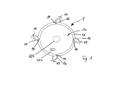
Figs la and lb show a prior art guide device 100 in isometric and cross-
sectional views respectively, comprising a
tube 110 that has a hub 120 attached to a proximal end thereof. The hub 120
has a passageway therethrough in
communication with the bore of the tube 110 and has a screw thread on its
external surface.
The guide device 100 is installed for use in the skull of a patient by first
drilling a hole along a desired trajectory in
the skull guided by a stereoguide. The guide device's tube 110 is cut to an
appropriate length to provide access to a brain
target e.g., for a cannula to be delivered through the tube 110. The tube 110
is delivered over a probe that is guided by the
stereoguide through the hole formed in the skull such that when the distal end
of the tube is at its planned location the guide
device's hub 120 is secured in the pre-formed hole in the skull. With an
appropriately sized drill hole the fixation may be a
press fit or if pre-tapped it may be a screw fit or alternatively it may be
bonded in the drill hole with acrylic cement. The probe
is removed and the guide device 100 can remain, installed, at least
temporarily, in the head of a patient to allow other
neurosurgical apparatus such as a cannula to be guided therethrough to reach
targets within the brain.
In some circumstances, the guide device 100 may be left in the skull and brain
of a patient for a prolonged period
of time. The guide device 100, which is fixed to the skull, does not move with
the brain as the brain moves within the skull.
Therefore relative movement of the brain against the tube 110 of the guide
device 100 may occur and cause trauma to the
brain tissue in the locality of the tube 110. The guide device 100 does not
provide a seal between its bore and the surgical
device that passes there through. There is thus a space between the guide
device 100 and a surgical device through which
infection can potentially enter into the brain. The guide device 100 does not
provide a means of securing a surgical device
that is delivered through its bore. For example, when the guide device 100 is
used to deliver a Deep Brain Stimulation (DBS)
lead, the lead is bent through 90 as it exits the hub 120 of the guide device
100 and is fixed to the skull by compression
under a bone plate secured to the skull with small screws. This fixing process
is awkward to carry out and carries the risk of
inadvertently moving the DBS lead from its target location.
Figs 2a and 2b show a guide device 200, in accordance with the present
invention. Fig 2c shows a similar guide
device 200 to that of Figs 2a and 2b in cross sectional view. The example of
figure 2c differs by having smaller broaching
teeth 225 as discussed further below. The guide devices 200 are configured to
be implanted within the skull of a patient to
CA 03216973 2023- 10- 26
11
WO 2022/229662
PCT/GB2022/051104
provide a low profile access point for introducing apparatus into the brain,
along a selected trajectory. the device 200 also
provides means for securing the apparatus to the guide device 200.
The guide devices 200 comprise a guide hub 220 but do not comprise a guide
tube 110 as in the device of figures
la and lb.
The guide hubs 220 may be made of titanium or PEEK (polyether ether ketone) or
another biocompatible material.
A PEEK hub has the advantage of being a long-term implantable device that
causes no artefact when imaged with MRI and
will not heat up in a high magnetic field. Each hub 220 comprises a through-
bore 221 and has a conical portion 222 at its
distal end with a central hole 223 that forms the extreme end of the through-
bore 221. The hubs 220 further comprise a
proximal rim 224 at its proximal end. As will be explained in more detail
later, the rim 224 provides a hub datum HD, allowing
the distance between the hub datum HD and a brain target to be calculated.
The main bodies of the hubs 220 have a diameter (D) and length (L). The
diameter of the hub 220 through bore
221 and distal central hole 223 can be sized for guiding and securing a range
of surgical devices, for example ranging in
diameter from 0.5mm to 5mm. By way of example the dimensions of a guide hub
200 for use in delivering and securing a
device with a cross section diameter of 1.2mm may have a diameter (D) of the
main body of the hub 220 of around 4 to 5
mm. The hub 220 may be of a length (L) such that it can be fully implanted
within the thickness of the skull of the majority of
adults and children. Thus the length (L) may be around 4 to 5mm. The through-
bore 221 may be around 3mm in diameter at
the proximal end of the hub 220. The central hole 223 at the extreme end of
the through-bore 221 may be typically about
1.2mm in diameter. The rim 224 may be around 0.5mm in length (11) and 0.5mm
thick, with an outside diameter of around
5mm and an inside diameter of around 4mm. Guide hubs 220 with alternative
dimensions are envisaged for use in
delivering devices with different diameters to the brain in humans and other
animals, or when employing them in other parts
of the human body.
As can be seen in Figs 2b and 2c, in these examples, the conical portion 222
tapers at an angle of around 45 over
a length (L) of around lmm. This provides an angled surface of about 450 on
the outside for the hub 220 and a similarly
angled inner surface, which provides a surface for apparatus to sit within the
hub 220.
Referring to Figs 2a, 2b and 2c, the hubs 220 comprise broaching teeth 225 for
preventing rotation of the hub 220
when fixed to the skull. The broaching teeth 225 may start a distance (dl)
from the rim 224 to allow bone to regrow within
this gap when installed in the skull and thereby provide a stable long-term
implant. The distance (dl) may provide a gap
between the rim 224 and the broaching teeth 225 of 0.5mm, for example. In some
embodiments, the broaching teeth 225
may extend to a similar width as that of the outside diameter of the rim 224,
as can be seen in Fig 2b. In figure 2c smaller
broaching teeth are illustrated.
In the examples shown in Figs 2a, 2b and 2c, the hub 220 is provided with six
broaching teeth 225 which are
equally spaced around the hub 220. The shape and angle of the broaching teeth
225 may be adjusted from that shown in the
examples in the figures to allow insertion into different bone densities or
bones of different strengths. In the examples
broaching teeth 225, each have a triangular cross-section which is configured
to bite into and lock the hub 220 into the
surrounding bone as the hub 220 is driven into the bone. Other means for
prevention of rotation of the hub in a skull can be
provided, for example ribs such as axially extending ribs, disposed around the
circumference of the hub.
As an alternative to broaching teeth 225, a guide hub 220 may be provided with
an external thread which is
arranged to bite into the skull or the hub may have an interference pattern
(not shown). The interference pattern, such as an
array of protrusions, can provide for an interference fit to provide locking
of the hub 220 into the surrounding bone as the hub
220 is pushed into the bone.
Figs. 17a, 17b, and 17c show an example in which the guide hub 220 is provided
with an external thread 1702.
The external thread 1702 is a self-tapping thread arranged to bite or cut into
the skull. This enables the hub to be rigidly
CA 03216973 2023- 10- 26
12
WO 2022/229662
PCT/GB2022/051104
secured to the skull. In addition, the threads cut by the external thread 1702
in the skull can later be used to retain other
threaded components following removal of the guide hub 220. For example, a
threaded bone plug may be inserted using the
same hole to seal the hole in the skull. The external thread 1702 preferably
has relatively deep grooves between the
threads. Thereby, the external thread 1702 is configured to accommodate bone
chippings produced when the external
thread 1702 cuts into the skull. The minor diameter of the external thread
1702 may be smaller than the diameter of the drill
hole into which the guide hub 220 is inserted by at least 0.2mm, and
preferably at least 0.4mm. This allows the guide hub
220 to be inserted more easily, and may help in encouraging bone regrowth
around the guide hub 220 due to the bone
chippings in the external threads 1702. As shown in Figs. 17a, 17b, and 17c,
the guide hub 220 may also have a region
above and/or below the external thread 1702 in which the outer diameter of the
guide hub 220 matches the minor diameter
of the external thread 1702, but in which no thread is provided. This provides
further space to accommodate bone chippings
that may be produced when the external thread 1702 cuts into the skull.
A proximal rim of the guide hub 220 may comprise hub engagement features for
engagement with the hub
insertion tool, which will be discussed in more detail below. The hub
engagement features may comprise any suitable
feature, for example grooves, protrusions, or notches. In the example of Figs.
17a-17c, the hub engagement features
comprise notches 1704 in the rim of the guide hub 220. Other examples of
possible shapes include slots, holes, or
castellations in the upper (proximal) surface of the guide hub. The hub
engagement features allow a higher torque to be
more easily and reliably applied to the guide hub 220 during insertion. This
is particularly advantageous where the guide hub
220 comprises self-tapping threads, because it allows for the easy application
of sufficient force for the threads to cut into the
bone.
A further embodiment of the guide hub 220 may have an external thread that is
inserted into a tapped hole, rather
than being self-tapping. This would be a preferred solution when the guide hub
220 is made from a material that is not
suitable for forming self-tapping thread, for example PEEK. In this instance
the jig would have an extra tool to tap the hole to
the desired depth.
Referring now to Figs 2d-2f, the internal arrangement of a hub 220 is as
follows. The through-bore 221 of the hub
220 comprises a double entry female thread 226 extending from the proximal end
of the conical portion 222. The thread 226
used in the presently described example is an M4 thread and has a pitch of 2mm
and sweeps for half a revolution. The pitch
may be adjusted for other threads used with hubs 220 of different dimensions.
As shown in Fig 2d, each half revolution of thread 226 comprises a notch 227.
A detail view of one of the notches
227 is shown in Fig 2e. Each notch 227 is arranged to engage with a rib (not
shown) on an apparatus to be inserted and
locked into the hub 220. The notch 227 comprises a 0.08 mm2 flat surface 228
of length (13) of 0.2mm, which extends radial
to the through-bore 221 of the hub 220. This flat surface 228 engages with the
rib on the apparatus to be inserted. For the
example hub 220 shown and utilising an M4 thread 226, the notch 227 starts
0.34mm from the start of the thread 226, which
is 0.1mm of lengthwise (L) translation into the hub 220 from the start of the
thread 226. As shown in Fig 2e, the notch 227
comprises a fillet 229 which is provided to allow the rib on an apparatus to
be inserted to slide past the notch 227 and
provide compression of the notch 227 and/or the rib on the apparatus. Once the
rib has passed the fillet 229, it is securely
engaged within the thread 226 and thus the apparatus is locked within the hub
220. Fig 2f shows a cross-sectional view of
the hub 220 of figure 2b, showing the broaching teeth 225 and the notch 227.
Alternative locking screw thread arrangements
such as of the Spiralock type may be employed in the through bores 221 of
hubs 220.
In an exemplary use of the hub 220, an exemplary cap 300 is described with
reference to Fig 3a and 3h. The cap
300 is in the form of an overmould on a catheter or (in this example) a
cannula 393 that may be made of PEEK or comprise
PEEK. A cannula of PEEK has the advantage over the use of many other plastic
materials in that it is robust, stiff and
biocompatible and even with an external diameter in the region of 0.5mm it can
be delivered over several centimetres into
CA 03216973 2023- 10- 26
13
WO 2022/229662
PCT/GB2022/051104
brain tissue without deflecting from its trajectory. A further advantage of
PEEK is that it can be readily cut and unlike fused
silica, which is used in some CED cannulas, it is not brittle. PEEK can be
made radio-opaque so that its position in brain
tissue can be established with x-ray and CT imaging. The overmould acts as
both a depth stop, and means of securing the
catheter or cannula 393 to a guide hub. In this example the cannula 393
includes a protective sleeving 393a extending
proximally from the cap 300. Prior to insertion of the cannula 393 through a
guide huh 220 it is cut to a desired length (cap to
cannula tip length) in a jig. The cap 300 has a plurality of radially outwards
extending recesses (in the form of grooves) 324,
on the upper surface. In this example six recesses 324 are provided. The
radial recesses 324 allow engagement of a
complementarily shaped end of a hollow screwdriver to turn the cap 300 within
a hub 220, thereby screwing the cap 300
down the threads of the hub 220 and locking the cap 300 within the hub 220 by
engagement of ribs 327 with the notch 227 of
the hub 220. It is not essential that the guide hub 220 comprise the notch
227, and where the guide hub 220 does not include
the notch 227, the cap 300 need not comprise the ribs 327. An example of a cap
300 without ribs is shown in Figs. 18a to
18d. The hollow screwdriver may have a generally conventional hexalobular or
"star drive" end for engaging the recesses
324. The end of the hollow screwdriver may attach by an interference fit to
the radial recesses 324. This interference fit (or
'clip' fitting) is convenient as the cap 300 can be retained on the
screwdriver whilst it is being put into position and screwed
into a guide hub.
As also shown in Figs 18c and 18d, the radial recesses 324 also provide a
means of retaining flexible cylindrical or
tubular devices, such as cannula 393, after implantation into a patient when
they are bent through 900 so as to provide a low
profile, for example when they are chronically implanted under the scalp. The
radial recesses follow a 900 radius of curvature
(324a) out from the central axis of the cap. This radius defines and controls
the bend radius of a device being fitted. Thus for
devices with larger diameters the diameter of the radial groove will be
greater. Typically larger diameter devices will require
a larger radius of curvature, to avoid kinking or collapse of a tubing wall.
These dimensions will therefore determine the size
of the cap and guide hub where bending of a device is employed. In the example
shown in Fig. 3a and Fig. 3b a sleeving
393a is made polyurethane and the cannula 393 of PEEK tubing, both of which
are overmoulded with the cap 300. The
sleeving 393a protects the fine PEEK cannula 393 and, being made of more
compliant material than the cannula, facilitates
its retention in an interference fit within recesses 324.
The cap 300 comprises a corresponding double male thread 326 to engage with
the double entry female thread
226 of the hub 220 (figure 2c). The cap 300 further comprises a cap conical
portion 322 at its distal end which is shaped and
configured for sealing engagement with the conical portion 222 of a hub when
the cap 300 and the hub 220 are locked
together. The engagement of the cap 300 within the hub 220 and locking in
sealing engagement will be described further
later.
In a second example use of the hub 220, a second example of a cap 400 is used,
as shown in Fig 4a and 4b. The
cap 400 comprises a central through-bore 421 for passage of a device such as
a, probe, electrode, catheter, cannula or
other apparatus. The cap comprises a plurality of radial recesses 424
typically in the form of a hexalobular configuration on
the upper surface. The radial recesses 424 allow engagement of a hollow
screwdriver as discussed above with reference to
the examples of figures 3a and 3b. The cap 400 differs from the cap 300 in
that the cap 400 is not an overmould on a device
and does not comprise a cap conical portion at its distal end. Instead, the
cap 400 comprises a cap through bore 421 and a
cap flat portion 422 at its distal end which is configured to engage with a
seal within an alternative hub 220, as will be
described further later. The cap 400 also comprises a 90 radius of curvature
(424a) for its radially extending recesses
(grooves) 424.
A method of insertion of the hub 220 into the skull 500 of a patient is now
provided with reference to Figs 5a-5f.
Firstly, as shown in schematic figure 5a, brain imaging is performed to
determine the location of a target 501 and a trajectory
502 with respect to a stereoguide datum 503. A stereotactic guidance system
(not shown) is registered with respect to the
CA 03216973 2023- 10- 26
14
WO 2022/229662
PCT/GB2022/051104
target 501 and the trajectory 502. Registration of the stereotactic guidance
system includes setting of the stereoguide datum
503 of the stereotactic guidance system at a predetermined distance from the
target 501. Commercially available stereotactic
guidance systems typically set their stereoguide datum 503 at around either
140mm or 160mm from the target 501.
However, it will be understood that the chosen distance between the
stereoguide datum 503 and the target 501 can be
varied, for example when using a robotic arm to guide surgery, provided the
distance used is known.
Imaging scans provide the surgeon with information relating to the skull
thickness and location and arrangement of
areas of interest within the brain. The known distance between the stereoguide
datum 503 and the target 501 allows the
surgeon to accurately plan surgery using instruments delivered using the
stereotactic guidance system.
Datum Measuring and Tool Setting
Conveniently the setting of tools and devices for surgery when employing the
guide hubs of the invention makes
use of the jigs of the invention, as described in more detail and with respect
to figures 5 to 14 as discussed further below.
More generally, and as illustrated in figure 5b, a datum measuring tool 535
with a conical distal end is passed
through the stereoguide that is set to the target trajectory. The distance
from the datum on the stereoguide 503 to the surface
of the skull 500 is measured, from which the penetration depth of the tools
that are required to implant a guide hub into the
skull are determined. To prepare the skull 500 for delivery of a hub 220, a
facing tool 540 is mounted in the stereotactic
guidance system and is brought into contact with the surface of the skull 500
along the trajectory 502, to create a flat surface
541 on the surface of the skull 500, as shown in Fig Sc. This is to ensure
that a fine pilot drill 550 which is subsequently
delivered along the trajectory will not be deflected as it might be if
engaging with the curved surface of the skull 500. The flat
surface 541 provides a recess around 1mm deep from the original skull top
surface.
As shown in Fig. 26, the facing tool 540 may have a stepped profile with a
distal cylindrical cutter 1530 that has a
smaller diameter than a more proximal cylindrical cutter 1540. This
arrangement has particular advantage when creating a
featured hole in a skull 500 that is acutely curved and thin, as for example
in a child's skull. The smaller distal cutter 1530
will create a flat surface in the bone so that the pilot drill 550 will engage
orthogonally with the bone surface to ensure that it
drills concentrically, as discussed above. For example the distal cylindrical
cutter 1530 may be between 0.5-1.5mm deep, for
example 1 mm deep, with a diameter of 2-4mm, for example 3mm. This steps up to
the larger diameter proximal cylindrical
cutter 1540, which is preferably larger than the diameter of the rim of the
guide hub 220. For example, if the diameter of the
guide hub's rim is 5mm then the diameter of proximal cutting face may be 6mm.
The larger diameter flat surface created by
the stepped facing tool ensures that the core drill that creates the profiled
hole will engage with the bone orthogonal to the
now flat surface and will not be deflected from its trajectory.
After making the flat surface 541, a pilot drill 550 is then used to penetrate
the full thickness of the skull 500,
thereby creating a pilot hole 551 as shown in Fig 5d. A core drill 560 with a
nib at its distal end is then inserted into the pilot
hole 551 which guides it to form a profiled hole 561 in the skull 500, as
shown in Fig 5e, for allowing press fitting of an
implantable hub 220 therewithin. The core drill 560 opens the pilot hole 551
and provides internal profiling to allow
subsequent engagement of the hub 220 within the profiled hole 561 in a secure
and low-profile manner.
A detailed view of the profiled hole 561 is shown in Fig 6a and of the core
drill 560 in Fig 6b. Starting from the
proximal end the core drill 560 comprises a step 562 which is configured to
engage with the skull and create a 1mm deep
and 5mm diameter recess into which the 0.5mm high rim of the guide hub will be
located. The core drill 560 further
comprises a main body 563 which opens the pre-made pilot hole to around 4mm in
diameter for receiving a hub 220 (figure
5f discussed below). Additionally, the core drill 560 comprises a conical
surface 564 towards its distal end which forms a
shoulder 565 in the skull. The core drill 560 also comprises a nib 566 at its
distal end for guiding the core drill 560 into the
pilot hole. The profiled hole 561 formed as shown in Fig 6a provides a press
fit for an implantable hub 220.
CA 03216973 2023- 10- 26
15
WO 2022/229662
PCT/GB2022/051104
The profiled hole 561 has been made along the desired trajectory 502 (figure
5a). Therefore when the hub 220 is
inserted into the hole the passage through the hub 221 and central hole 223
are aligned along the trajectory.
Figs. 27a-27d show the equivalent process of preparing the skull for inserting
the guide hub 220 using the stepped
profile facing tool 540 in a highly curved skull surface. Fig. 27a is
analogous to Fig. 5c, and shows the facing tool 540 being
used to create the flat surface 541. Fig. 27b is analogous to Fig. 5d, and
shows the pilot drill 550 being used to create the
pilot hole 551. Fig. 27c is analogous to Fig. 5e, and shows the core drill 560
engaging with the pilot hole 541 to form the
profiled hole 561. The guide hub 220 can then be inserted as shown in Fig.
27d. As seen in particular from Figs. 27c and
27d, the stepped profile created by the facing tool 540 allows the core drill
560 and guide hub 220 to be brought into position
on the skull surface without interfering with the highly curved skull surface
in a manner which could cause deflection of the
core drill 560 or improper insertion of the guide hub 220.
Referring now to Figs 5f and 5g, the insertion of a hub 220 into the profiled
hole 561 in the skull 500 is explained.
To insert the hub 220 into the profiled hole 561, the hub 220 is attached to
an insertion tool 570 which is shown in Fig 5f and
in more detail in Fig 5g. The insertion tool 570 comprises a shank 571 and a
threaded distal end 572. The threaded distal
end 572 comprises a male double entry thread which engages in the female
thread 226 of the hub 220 by mating of the
threads of the hub 220. In this example, the insertion tool 570 does not
comprise a locking screw thread, thus allowing the
insertion tool 570 to easily be removed from the hub 220 after the insertion
tool 570 has delivered the hub 220 into the
profiled hole 561.
The hub 220 can be aligned and accurately positioned in the profiled hole 561
of the skull 500 using the insertion
tool 570. The shank 571 is dimensioned to be operable with a stereotactic
guide. For example, insertion tool 570 comprises
a shank of 150mm length and 10mm diameter. This allows the insertion tool 570
to be used with existing stereotactic guides
and provides a sufficiently long insertion tool 570 to deliver the hub 220 to
the profiled hole 561 using the stereotactic guide.
The insertion tool 570 also comprises a chamfer 573 between the threaded
distal end 572 and the shank 571. The chamfer
573 allows for a line of sight between the hub 220 and the medical
professional when the hub 220 is brought into the profiled
hole 561. The insertion tool 570 can be used to drive the hub 220 into the
skull 500 with a force sufficient to enable
broaching teeth or other external profile to bite or cut into the skull 500
and thereby secure the hub 220 into the skull 500 with
the through-bore 221 co-axial with the trajectory 502 to the target 501. When
an external thread or interference pattern is
used instead of broaching teeth 225, the insertion tool 570 may have further
features that are used to immobilise the tool with
respect to the hub internal thread to allow an unscrewing action between the
hub external thread and bone.
The insertion tool 570 can then be unscrewed from within the hub 220, leaving
the hub 220 implanted in the
profiled hole 561 in the skull 500.
Figs. 19a and 19b show another example of the insertion tool 570. A closer
view of the distal end of the insertion
tool 570 is shown in Figs. 20a and 20b. As discussed above, the hub insertion
tool 570 comprises a rod 1804 with a
formation at its distal end for engaging with the second formation in the
surgical guide hub 220. In this example, the insertion
tool 570 is further configured to engage with the guide hub 220 via tool
engagement features 1802. The tool engagement
features 1802 may be configured to engage with hub engagement features 1704 on
the guide hub 220. The insertion tool
570 may comprise a corresponding number of tool engagement features 1802 to
match the number of hub engagement
features 1704 on the guide hub 220. Preferably, a plurality of tool engagement
features 1802 are provided spaced around
an outer circumference of the insertion tool 570. For example, at least three,
optionally at least four, tool engagement
features 1802 may be provided. The tool engagement features 1802 may have any
suitable shape. The shape of the tool
engagement features 1802 may be chosen to correspond to the shape of the hub
engagement features 1704. For example,
the tool engagement features 1802 shown in Fig. 21 have the form of
castellations and engage the notches that form the hub
engagement features 1704. Where the hub engagement features 1802 comprise
holes as mentioned above, the tool
CA 03216973 2023- 10- 26
16
WO 2022/229662
PCT/GB2022/051104
engagement features 1802 may comprise pins sized to fit into the holes.
Preferably, the shapes of the tool engagement
features 1802 and the hub engagement features 1704 are chosen such that the
features can be easily engaged together and
do not slip or easily become disengaged during use.
The formation at the distal end of the rod 1804, which in this example is the
threaded distal end 572, may be
configured to be movable relative to the shank 571 of the insertion tool 570.
Preferably, the formation at the distal end of the
rod 1804 is rotatable relative to the shank 571. The tool engagement feature
1802 may be provided on the shank 571 of the
insertion tool 570, such that the shank 571 of the insertion tool 570 engages
with the guide hub 220 via the tool engagement
features 1802. This means that, following insertion of the guide hub 220 into
the aperture, the insertion tool 570 can easily
be disengaged from the guide hub 220 by moving (e.g. rotating) the formation
at the distal end of the rod 1804 relative to the
shank 571, without disturbing the placement of the guide hub 220 in the
aperture. In addition, the engagement of the
insertion tool 570 with the guide hub 220 via the tool engagement features
1802 can be used to apply a force to the guide
hub 220 to insert the guide hub 220 into the aperture formed in the skull.
This is particularly advantageous when the guide
hub 220 comprises self-tapping threads, and a larger rotational force is
required to cut into the skull as the guide hub 220 is
inserted into the aperture.
Fig. 21 shows another view of the distal end of the insertion tool 570,
illustrating the tool engagement features
1802 that engage with hub engagement features 1704 on the guide hub 220. As
shown, the engagement of the tool
engagement features 1802 with the hub engagement features 1704 allows for
efficient application of rotational torque to the
guide hub 220 for insertion of the guide hub 220 into the aperture.
The insertion tool 570 may also comprise a depth stop 1806 as shown in Figs.
19a and 19b. The depth stop 1806
is analogous to the datum markers 537, 538, 539 discussed below in relation to
other tools used in implanting the guide hub
220. The depth stop 1806 helps to prevent over-insertion of the guide hub 220
into the aperture. The depth stop 1806 may
provide a visual and/or tactile indication of when the guide hub 220 has been
inserted to the correct depth by engaging with
the stereoguide datum 503. The depth stop 1806 may be movable with respect to
the rod 1804 and/or shank 571 of the
insertion tool 570. Before inserting the guide hub 220, the depth stop 1806 is
set at the correct position along the insertion
tool 570 such that the depth stop will engage the steroguide datum 503 when
the guide hub 220 has been inserted to the
correct depth in the aperture. The setting of the position of the depth stop
1806 may be carried out using the jigs of the
invention.
A system including the guide hub 220 may include a shortened tool 1850 as
shown in Figs. 22a and 22b. A distal
end of the shortened tool 1850 is substantially similar to the distal end of
the insertion tool 570 and comprises the threaded
distal end 572 and/or the tool engagement features 1802. The shortened tool
1850 may comprise a shank 571 and rod 1804
that are movable relative to one another as for the insertion tool 570.
However, the length of the shortened tool 1850 is less
than the length of the insertion tool 570. This facilitates easier handling of
the shortened tool 1850. The shortened tool 1850
may not comprise a depth stop 1806. This also facilitates easier handling of
the shortened tool 1850. The shortened tool
1850 may be particularly suited for removal of the guide hub 220, where it is
not necessary to control the axial position of the
tool as accurately as during insertion of the guide hub 220. The shorter
length and/or lack of the depth stop on the shortened
tool 1850 also remove the need to handle the shortened tool 1850 using a
stereoguide, which further simplifies use of the
shortened tool 1850. The shortened tool 1850 may have a narrower diameter than
the insertion tool 570. This gives the
user a higher sensitivity to the force required to remove the guide hub 220,
thereby improving control during the process of
removing the guide hub 220.
The hub 220 can be located in the skull wholly within the recess 561
previously formed by the core drill. If desired
the through bore of the hub 220 can be sealed, when not used for delivery of a
device through the skull, by inserting a grub
screw into the proximal end of the hub, which when fully inserted with e.g.,
an Alan key, has a proximal end that becomes
CA 03216973 2023- 10- 26
17
WO 2022/229662
PCT/GB2022/051104
flush with the proximal face of the guide hub.
Figs 5h-5k, show an example use of the hub 220 when installed in the skull
500. As shown in Fig 5h, the hub 220
is aligned along the trajectory 502, so that devices, and tools, such as
cannulas, probes, electrodes or other neurosurgical
apparatus provided through the hub 220 will also be directed along the
trajectory 502 towards the target 501. In an example
of the delivery of such apparatus, a track may be made through the brain
tissue between the hub 220 and the target 501 by
use of a track forming device 580 shown in Fig 5i. In some procedures, a guide
tube 581 may be inserted along the track
formed by the track forming device 580. The guide tube 581 can be delivered
through the through-bore of the hub 220 and
may comprise a conical enlarged diameter proximal end which can seat against
and seal against the conical portion 222 of a
hub 220. As shown in Fig 5k, a cannula 582 may then be inserted through the
guide tube 581 to reach the target 501.
In some examples, a device may be delivered through the hub 220 without the
use of the guide tube 581. The
device may be locked into the guide hub 220 in a similar fashion to the
cannula 393 discussed above by providing the device
with its own screw threaded portion for engaging with the screw thread within
a hub 220 (figures 2 to 4). The screw threaded
portion may act as a stop to indicate the intended position (depth into the
brain) to which the device should be inserted, and
may prevent the device being inserted beyond its intended depth. The screw
threaded portion may be configured to rotate
independently of the rest of the device, to avoid coiling of the wire/tube of
the device as the threaded portion is screwed into
place. This could be achieved, for example, using one or more circumferential
grooves with which corresponding protrusions
on the threaded portion engage.
Figure 7 shows an example of insertion of a device through the hub 220 in
sequence of schematic views from left
to right. In this example the device 593 is a Deep Brain Stimulation (DBS)
electrode. The hub 220 is firstly inserted into a
profiled hole in the skull as previously described and the track forming tool
580, mounted in an insertion tool, is then passed
through the hub 220 to create a track along the desired trajectory in the
brain. The insertion tool for the track forming tool
may be the hub insertion tool 570 as shown here. In this example, the hub 220
comprises a seal 230 which is in a free non-
compressed and non-sealing state as the tracking tool 580 is passed through
the hub 220. The tracking tool 580 is then
removed and a cap 400 is brought into the hub 220. Since the presently
described example hub 220 comprises a seal 230 in
the form of an 0-ring seal, the cap 400 comprises a cap flat portion 422 as in
the example shown in Figs 4a and 4b, rather
than a cap conical portion 322 as shown in Figs 3a and 3b.
Use of a hollow screwdriver 590 and through-bore of the cap 400 allow delivery
of the device 593 through both the
hollow screwdriver 590 and the cap 400. Turning the cap 400 with the hollow
screwdriver 590 moves the cap 400
downwards and into engagement with the seal 230, thus compressing the seal 230
axially and thereby expanding it radially.
The seal 230 then provides a fluid, gas and bacterial seal between the hub 220
and the cap 400 that securely grips the
device 593 passing through hub 220.
In the example of figure 7, the hollow screwdriver 590 is configured such that
a device 593 enters its proximal end
and exits the screwdriver 590 from the distal end. Advantageously such a
screwdriver is provided with an air vent hole at its
distal end so that air is easily vented as the DBS electrode is inserted into
the brain. An alternative arrangement is shown in
Fig 8. Alternative screwdriver 591 has a hexalobular formation 592 at its
distal end, but with one lobe of the six absent (see
also figures 16a and 16b discussed below). The hexalobular formation engages
the recesses of the cap 400 with an
interference fit to attach the screwdriver temporarily to the cap. A cannula
593 extends through the cap 400. The screwdriver
591 comprises an axially extending slot 594 at its distal (head) end so that
the cannula 593 can exit out the side of the
screwdriver 591. This arrangement can allow a device with a part on its
proximal end that will not pass through the bore of
the hollow screwdriver to be delivered into a guide hub. For example, the end
of cannula 593 may have a fluidic connector
for joining to a fluid supply line which has a diameter larger than the bore
of the screwdriver. The slot 594 in screwdriver 591
also provides a convenient air vent. In some examples screwdriver 591 may be
hollow along its length and so able to be
CA 03216973 2023- 10- 26
18
WO 2022/229662
PCT/GB2022/051104
used for delivery of devices as shown in ether figure 7 or figure 8.
As shown in Figs. 23a and 23b, the axially extending slot 594 may extend to
the extreme proximal end of the
screwdriver tool, such that the slot 594 extends along the entire length of
the screwdriver 591 from the distal end to the
proximal end. As described in relation to Fig. 8 above, this allows a device
593 with a part on its proximal end that will not
pass through the bore of the hollow screwdriver 591 to be delivered into a
guide hub 220 using the hollow screwdriver 591.
However, having the slot 594 extend along the entire length of the screwdriver
591 allows the device 593 to be positioned
approximately along the axis of the screwdriver 591 through the bore of the
screwdriver 591. This is illustrated in Fig. 24,
which shows the screwdriver with a device positioned along its axis ready for
delivery. This allows the hollow screwdriver
591 to rotate around the device 593, thereby preventing the device 593
becoming tangled or coiled around the screwdriver
591 as the screwdriver 591 is rotated to deliver the device 593.
The screwdriver 590 01 591 may further comprise a latch 1902, for example in
the form of a rotating collar or
rotating disc as shown in Figs. 23a and 23b. The latch 1902 may be configured
to reversibly block the slot 594 (for example
by blocking entry to the slot 594 from a radial direction) along at least part
of the length of the slot 594. The latch 1902 is
preferably provided at or near to the proximal end of the screwdriver 591. The
latch 1902 may act to hold the device 593
within the hollow bore of the screwdriver 590 and prevent it from falling out
of the screwdriver 591 again via the slot 594.
This can reduce the chance of the device 593 becoming coiled or tangled around
the screwdriver 591 as the device 593 is
delivered or removed from the guide hub 220.
Referring back to Fig 7, after locking of the cap 400 in the hub 220, the
device 593 can be bent into one of the
radially extending recesses 424 of cap 400 to provide a low-profile and secure
attachment. At the end of the process shown
in Fig 7, the inserted apparatus has been locked within the hub 220 and a gas,
fluid and bacterial seal has been created. The
device shown in figure 7 is a DBS electrode, however such methods can also be
employed, with other devices such as
catheters or cannulas.
Removal of a device from the patient can be straightforward. Referring again
to the sequence of figure 7, but
starting from the right hand view, the device can be removed from the recess
424, and a hollow screwdriver of one of the
types 590 or 591 inserted over the device to engage in the recesses 424.
Advantageously the screwdriver is of the type 591
with a side slot 594. The screwdriver 591 can be placed onto the cap with the
device 593 accepted in slot 594. The
screwdriver can then unscrew the cap 400 to release the seal and in this way
the cap 400 and apparatus can then be easily
removed after use.
The implanted guide hub 220 can facilitate repeated access to intracranial
targets without the requirement for
further stereotactic surgery. To replace a faulty electrode or a ventricular
catheter for example, the device is removed as
described above and the cap 400 is screwed back into the hub 220 without
compressing the 0-ring. This aligns the hollow
screwdriver 590 along the axis of the trajectory 502 to the target 501. The
distance from the hub datum HD to the target 501
is known and will have been recorded in the surgical notes (figures 2b and
5a). The hub datum HD to target 501 distance is
added to the length of the proximal end of the screwdriver 590 to the hub
datum HD distance and a depth-stop is secured to
the replacement device this same distance from its distal end. The replacement
device is now delivered down the hollow
screwdriver 590, cap 400 and guide hub 220 to its target 501 which is reached
when the depth stop engages with the
proximal end of the screwdriver 590. The screwdriver 590 is rotated to lock
the device in the guide hub 220, the depth-stop is
then removed followed by the screwdriver 590, leaving the replacement device
in situ, with its distal end at the target.
Approximately one third of Intraventricular catheters implanted for the
treatment of hydrocephalus will become
blocked and need replacing every 10 years. Re-accessing the ventricle for
replacement of a catheter can be technically
difficult. Advantageously the guide hub may be employed to accurately place
and secure a ventricular catheter and simplify
its accurate replacement should it become blocked. In such an example, removal
of a blocked catheter is achieved by
CA 03216973 2023- 10- 26
19
WO 2022/229662
PCT/GB2022/051104
attaching a screwdriver 591 to the cap 400 and unscrewing it. This releases
the catheter which can then be withdrawn
through the side slot in the distal end of the screwdriver 591. A new catheter
is now delivered through the hollow screwdriver
591 and through the cap 400 and hub 220 to the same depth as the original
catheter. The new catheter is secured by re
locking the cap 400 into the hub 220.
Re-access to the same target 501 for repeated treatment without the need for
further stereotactic surgery may also
be achieved with the guide hub 220 by replacing a device such as a lesioning
electrode, catheter or cannula with a plastic
stylet of the same length. The stylet, fixed in the hub 220 by a proximal
threaded cap will maintain patency of the track and
facilitate re-access to the target 501 days, months or years later.
Alternatively, following removal of a device a blind cap (not
shown but a cap 300, 400 without a central through-bore), may be located in
the hub 220 and secured and sealed in the
same manner as previously described with reference to either Fig 3a, 3h or 4a,
4b to provide safe sealing of the hub 220 to
prevent infection or loss of fluid from within the head. Alternatively, a grub
screw cap, with the same male thread as the cap
300, 400 may be screwed into hub 220 with an alien key such that its proximal
face becomes level with the proximal surface
of the hub. This will seal to a hub 220 providing a low-profile, reaccessible
alternative to other somewhat bulkier caps.
Referring again to figures 5 and 7, re-access to the intracranial target 501
can be achieved by removing the blind
cap, screwing a guide hub insertion tool 570 into the hub 220 which thereby
becomes aligned and fixed coaxial with the
trajectory 502 to the target 501. A probe is then inserted down the hollow
guide tube insertion tool 570 to the target which is
at a known distance from the hub datum HD (figure 2b). The probe is removed
leaving a track to the target 501 and the guide
hub insertion tool 570 is now removed. The cap 400 is attached to the
screwdriver 590 and screwed into the hub 220 without
compressing the 0-ring. As described above the device is now inserted through
the hollow screwdriver 590 or 591 to the
target and locked in position.
Using conventional methods of drilling on the surface of the skull to form a
profiled hole and deliver a device
typically requires many measurements to be taken, particularly when multiple
different pieces of equipment are used to form
the hole for the introduction of a hub. The risk of human error across the
entire surgical procedure increases when repeated
procedures are required, as the calculations of each step must be performed
again during the repeated procedure.
Jigs are now described which assist in setting tools for neurosurgery and
cutting the length of implantable devices
with reduced calculation and adjustment required.
A jig 600 is shown in Fig 9. The jig 600 is for setting the depth of insertion
of multiple neurosurgical tools and
devices into the skull or brain of a patient during neurosurgery. The jig 600
can be used for setting the tools and devices
used in surgical procedures such as those shown in figures 5a to 5k and
described above.
The jig 600 comprises an open rectangular frame and has an upper cross bar
that provides a tool aligning device
610 and has a representative datum 503' that represents the stereoguide datum
503 of Fig. 5a. The jig 600 has a lower
crossbar 640 with a target datum 641 in the form of a surface that corresponds
to the target 501 in a patient's brain shown in
Figure 5a. The tool aligning device 610 can be moved in parallel to the lower
cross bar 640 and its position fixed with
reference to the scale 624 so that distance between the representative datum
503' and the target datum 641 correspond to
the stereoguide datum to target 501 distance of the stereotactic guidance
system in use. For the commercially available
Cosman-Roberts-Wells stereoguide the distance between the stereoguide datum
and the target is set at 160mm. For the
Leksell0 stereoguide the distance is set at 190mm. When the jig 600 is used
exclusively with a stereotactic guidance system
with a fixed stereoguide datum to target distance, the jig 600 may be provided
with a fixed relationship between the upper
and lower cross bar 640 but otherwise the upper cross bar would preferably be
adjustable relative to the lower cross bar 640.
For example, the stereoguide datum to target distance may be varied by the
operator for a specific target when the
stereoguide is a surgical robot or when the stereotactic guidance system is an
instrument guide on a moveable and lockable
arm whose spatial relationship to a target in a patient's head, registered to
volumetric images, is tracked using optical,
CA 03216973 2023- 10- 26
20
WO 2022/229662
PCT/GB2022/051104
ultrasonic or electromagnetic sensors. In these latter circumstances the
stereoguide datum to target distance defined in the
planning software is set in the jig 600 for that individual target.
The tool aligning device 610 is provided with slots or grooves to receive and
align generally elongate tools and tool
stops and direct their distal ends orthogonally towards a moveable reference
guide 620 that is parallel to the tool aligning
device 610. The reference guide 620 is in a form of a bar parallel to the tool
aligning device 610 and is moveable relative to
the tool aligning device 610 whilst retaining the parallel relationship. The
means for maintaining a parallel relationship are
described hereafter and with reference to Figs 11 to 13. The reference beam
620 has an upper datum surface 621 that
represents the skull surface 500 when carrying out procedures such as
illustrated in figures 5a to 5k. The reference guide
620 can be moved to set a baseline length from the datum line 503' of the tool
aligning device 610 to the datum surface 621.
The jig 600 may further comprise a moveable cutting or depth measuring guide
630 having a surface 631 to be
located at selected distances from the target datum 641as will be explained in
more detail later. The moveable surface 630
is in the form of a bar parallel to and positioned below the reference guide
620 and above the lower crossbar 640 providing
the target datum 641. A further device cutting surface 635 may be provided at
the target datum 641.
As will be shown in other examples, the jig 600 may be laid at an angle, for
example 45 degrees to the horizontal.
This can be convenient in allowing tools placed on the jig 600 (e.g. located
in the aligning device 610) to move into place
under gravity.
The use of the jig 600 to prepare tools to make a profiled hole 561 in a
skull, such as illustrated in figures 5a to 5d,
is now described.
A stereoguide is aligned to the planned trajectory 502 directed to the target
501in the patient's brain.. After making
an incision to expose the surface of the skull 500 a datum measurement tool
535 in the form of a rod is held in the
stereoguide and brought into contact with the skull of the patient (figure
5b). The baseline length from stereoguide datum 503
to the skull 500 can be marked on the tool or measured. Conveniently, a datum
marker 536 is clamped to the tool at the
stereoguide to fix the start of the baseline length. The datum marker 536
takes the form of a collar that fits about the tool
535 and clamps to it by means of a grub screw. The datum measurement tool 535
is then transferred to the jig 600 and is
held in the tool aligning device 610 with the first tool datum marker 536
sitting in a slot of the aligning device 610 as shown in
figure 9. The bottom of the slot is part of the representative datum 503'.
The reference guide 620 is then moved up so that the datum surface 621 of the
reference guide 620 comes into
contact with the distal end of the datum measurement tool 535 and the
reference guide 620 is then locked or held in position.
Thus, the distance from stereoguide datum 503 to skull surface 500 on the
patient is established on the jig 600 as the
baseline distance from representative datum 503' to datum surface 621.
Alternatively the baseline length from 503' to 621 in the jig 600 can be set
by using a measured distance obtained
using the datum measurement tool 535 or by any other means such as a laser
rangefinder, other measuring tool, or imaging
technique employed with a robot arm or stereotactic frame.
The reference guide 620 has multiple offsets or channels through from datum
surface 621 which allow setting
different lengths for surgical tools and devices with different functions, as
will now be described.
For preparing a hole in the skull and inserting a guide hub 220 the sequence
may be as follows. A first offset 650
in the form of a depression in the datum surface 621 is for setting the facing
tool 540. A second offset 651 including a
channel through the reference guide 620 is for setting the pilot drill 550. A
third offset 652 is for setting the core drill 560.
Each offset 650, 651, 652 provides a distance from the datum surface 621
corresponding to a distance beyond the skull
surface on the patient to which each tool should extend when carrying out its
task during surgery. Therefore, the offsets 650,
651, 652 in the reference guide 620 to allow the setting of different tools
following only one initial measurement, i.e.
establishing the baseline length.
CA 03216973 2023- 10- 26
21
WO 2022/229662
PCT/GB2022/051104
To set the length of the facing tool 540 from representative datum 503', the
facing tool 540 is located in the tool
aligning device 610 and its distal end brought to the first offset 650. The
length of the facing tool 540 from representative
datum 503' to distal end is set by clamping a tool datum marker 537 to the
tool 540. The tool 540 can then be used with the
stereoguide to cut a flat face on the skull, as shown in figure 5c, boring
down to exactly the desired depth.
In a similar fashion, the pilot drill 550 is brought to the second offset 651
and the length required (to bore through
the skull but avoid entering the brain ¨ Fig. 5d) set by clamping a third tool
datum marker 538 to the pilot drill 550 after
advancing the pilot drill to the depth required to penetrate the skull, which
has been determined from the brain imaging scans
and can be set precisely using a scale 622 on the moveable reference guide
620. A similar approach is made to set the
core drill 560 for making the shaped bore to receive a guide hub 220 (Fig.
5e). In this way, the lengths of the tools required
can be set based on only the baseline length being measured by the user.
In this example, a first offset 650 of 1mm and a baseline length of 100mm
would result in the facing tool 540 being
prepared to a length of 101mm from datum 503 (or representative datum 503')
for preparing a flat face on a skull during
surgery. In other examples, the offset may be negative, that is to say the
offset may be a protrusion on the datum surface
621 extending towards the tool aligning device 610. In such an example, if the
first offset 650 is -2mm (i.e. a 2mm protrusion
towards the tool aligning device 610) and the baseline length is 100mm, the
tool concerned would be set at 98mm from
datum 503 for surgery.
In the above examples, each tool 540, 550, 560 is fitted with a tool datum
marker 537, 538, 539 that can be used in
conjunction with a stereoguide to progress the tool into the skull to a
carefully measured depth. The datum marker 537, 538,
539 may comprise an indicator 2301 that indicates whether the datum marker
537, 538, 539 is locked to the tool, or in an
unlocked state where it can be moved up or down the tool. An example of such
an indicator 2301 is shown in Figs. 25a to
25c. In Figs. 25a to 25c, the datum marker 537, 538, 539 uses a screw, which
is tightened to fit the datum marker 537, 538,
539 to the tool. Fig. 25a shows the indicator 2301 in the unlocked position
and Fig. 25b shows the indicator 2301 in the
locked position. The indicator 2301 allows the user to rapidly determine if
the datum marker 537, 538, 539 is locked, to
reduce the chance of accidentally moving the datum marker 537, 538, 539 if the
tool is removed from the jig with the datum
marker 537, 538, 539 not locked to the tool. The depth stop 1806 of the
insertion tool 570 may be provided with a similar
indicator 2301 to indicate when it is locked onto the insertion tool.
The jig 600 may also be used in a similar fashion, to assist in inserting a
guide hub 220 as illustrated in Figs 5e and
5f. The hub insertion tool 570 may be set with an appropriate length in the
jig 600, making use of a tool datum marker to
avoid over insertion of a hub 220 into the skull.
The use of the jig 600 to prepare surgical tools or devices for delivery
through a guide hub 220 into the brain is now
described.
Devices that may be delivered through a guide hub 220 include guide tubes,
electrodes and cannulas, however it
will be understood that other types of device may be delivered through the hub
220.
Referring still to Fig 9, the reference guide 620 comprises a through-channel
653 for allowing passage of a device
or tool therethrough, so that the device can extend downwards to the surface
631 of the cutting or measuring guide 630. In
this example, the reference guide 620 includes a guide hub 220 fitted into a
suitably shaped offset in the datum surface 621.
This allows a hollow hub introducer tool 570 to be inserted into the hub 220
in the jig 600. A tool such as a track making
probe 596 can be passed through the hub introducer tool 570, the hub 220 in
the jig 600 and the reference guide 620.
In this way, the length of a device or tool required to extend from the hub
220 can be set in the jig 600. In this
example, if the track making probe 596 is to prepare a track within the brain,
the length of the probe 596 from the hub 220 to
the desired position in the brain can be set as follows. The insertion tool
570, hub 220 and probe 596 combination are
arranged as shown in figure 9. A first grub screw 595, operated by finger
gripping, is located on the tool 570 for clamping the
CA 03216973 2023- 10- 26
22
WO 2022/229662
PCT/GB2022/051104
(thicker) proximal end 596a of the probe 596 passing through. A second grub
screw 595a (with an allen key socket) is
provided for clamping a datum marker in the form of a collar 536a, to the
proximal end 596a of probe 596. Collar 536a
provides a depth stop against the top surface of the insertion tool 570. The
use of different screw types, a finger operated
grub screw 595 and an allen key operated grub screw 595a, aids an operator to
use the correct screw when working with the
tools.
As shown in figure 9, the track making probe 596 extends to cutting or
measuring guide 630. Datum marker 536a
is then fixed to the proximal end 596a of the track making probe 596 by
tightening grub screw 595a. The probe can then be
retracted into the body of insertion tool 570 as suggested by arrow A, and
held in position by tightening the first grub screw
595 by hand. The insertion tool, hub and probe assembly (570, 220,596) can
then be removed from the jig and transferred
to a patient. The guide hub 220 can be inserted into position (figure 5f) and
the track making probe 596 then inserted
through hub 220 to the depth set on the jig ¨ where datum marker 536a rests
against the top surface of the insertion tool
570. Thus, the fitting of the guide hub 220 to a patient's skull and making a
track along a trajectory can be combined into one
operation, with one use of the insertion tool 570.
In this example of the jig, the reference guide 620 comprises a first
indicator 623 in the form of a first pointer which
indicates a point on a scale 624. The scale 624 provides measurement along one
side of the jig 600. The scale 624 provides
a distance from the target datum 641 of the lower cross member 640. Using this
scale 624, a surgeon can set the position of
the reference guide 620, if the baseline length is not provided by a datum
measurement tool 535. If, as in the present
example, a datum measurement tool 535 is used, the set baseline length can be
confirmed using the scale 624 The cutting
or depth measuring guide 630 also has an indicator 633 in the form of a
pointer which runs along scale 624. Using this
second indicator 633, the position of the measuring guide 630 can be set based
on a measurement provided by imaging
studies of the patient.
A surgeon may set all of the tools and devices before starting surgery on the
patient by making use of the jig 600.
This may be manually or by computer control of a motorised jig, making use of
scan data and the surgical planning software.
Alternatively, the surgeon may set the reference guide 620 and measuring guide
630 and then set tools or devices on the jig
600 as required throughout a surgical procedure. The hub insertion tool 570 or
another tool of the same type may be used to
deliver a track making probe 596 into the brain of the patient, and then be
set again on the jig 600 with the next device to be
inserted into the brain. In Fig 9, a further insertion tool, a guide tube
insertion tool 570a is used to deliver a second probe
597. The second probe in this instance is used to deliver guide tube 598 and
to create a track in the brain to target 501. In
the example shown in Fig 9, the second probe 597 is set to penetrate into the
brain to the full depth permitted by the jig. The
distal end of second probe 597 set onto the upper surface (target datum 641)
of the lower cross member 640.
The jig 600 can also be used to set guide tubes and cannulas. The reference
guide 620 comprises a profiled hole
561 which can match the depth within the throughbore of a guide hub 220. A
guide tube 598 is located in the profiled hole
561 and extends downwards. The guide tube can then be cut to the desired
length for insertion into the brain. The position
to cut the guide tube 598 can be measured using scale 624 to set the position
of guide 630 and the cut can be made using a
knife passing through cutting slot 634.
The jig 600 is also shown for setting a cannula 599. A cap 300 carrying the
cannula 599 is fitted into the reference
guide 620 in a profiled hole corresponding to the internal through bore of a
guide hub. The cannula 599 can then be cut to
length by a knife inserted through cutting slot 635. As shown in figure 9 the
cannula can be attached to a screwdriver 591
when being set in the jig 600. The screwdriver and cannula combination can
then be removed from the jig for insertion into a
patient.
Another jig 700 is now described with reference to Figs 10a and 10b. As can be
seen in perspective view Fig. 10b
the jig 700 includes side plates 797 that support the rectangular frame at an
angle of 45 degrees to the horizontal. This
CA 03216973 2023- 10- 26
23
WO 2022/229662
PCT/GB2022/051104
allows easy fitting of tools and devices to the jig and lets gravity assist in
locating them correctly in position. In this example
the jig includes a back plate 798 against which tools or devices may rest.
Like components to the jig 600 of Fig 9 are
designated by similar reference numerals with the addition of 100, e.g. the
reference guide 720 is generally similar in function
to the reference guide 620 in figure 9.
The jig 700 comprises a lower cross member 740 but a datum 741 corresponding
to the location of a target (501 in
figure 5a) is provided as the bottom end of scale 724; as slot 743 in cutting
device 742; and also as platform 755. Thus, the
distance from stereoguide datum 503 to a target 501 (figure 5a) is represented
on the jig 700 by the scale 724, i.e. by the
vertical distance from representative datum 503' to datum 741.
The jig 700 further comprises a second cutting device 744 with a corresponding
second cutting slot 745.
A convenient use of a hollow insertion tool 770 is now described with
reference to Fig 10a and 10b. The insertion
tool 770 is similar to the tool 570 shown in previous figures. As with the
corresponding arrangement shown in figure 9 the
tool 770 features a double grub screw arrangement. A first grub screw 795 is
located on the tool 770 for clamping a device
passing through t. A second grub screw 796 is provided for clamping a datum
marker 799 to the device thereby providing a
stop against the top surface of the screwdriver 790.
As shown in figure 10a, a probe 756 extends to platform 755. Datum marker 799
is then fixed to the distal end of
the probe 757 by tightening grub screw 796. The probe can then be retracted
into the body of tool 770 as suggested by
arrow A, and held in position by tightening the first grub screw 795. The tool
and probe assembly can then be fitted to a
guide hub in a patient's skull and grub screw 595 released to allow driving
the probe 756 into the patient's brain to the depth
previously set on the jig (platform 755).
In the jig 700, the reference guide 720 and cutting or depth measuring guide
730 are moveable and lockable.
As shown in figure 10a the jig 700 comprises two parallel outer guide rails
701 and 702 and a central guide rail 703
which is parallel to the two outer guide rails 701, 702. The central guide
rail 703 connects the lower cross member 740 to
the reference guide 720. The lower cross member 740 and back plate 798 provide
stability and rigidity to the jig 700. In this
example the back plate also includes a number of grooves 746 for accepting the
bodies of tools being set.
The outer guide rails 701, 702 provide a means by which the reference guide
720 and the cutting or measuring
guide 730 can be moved whilst remaining parallel to each other and to the tool
aligning device 710. The reference guide 720
has a first locking screw 747 which can be turned to clamp the reference guide
720 to the central guide rail 703. Thus the
reference guide 720 can be fixed in a selected position. The measuring guide
730 comprises a similar second locking screw
748 which screws down onto the backplate 798 for locking engagement.
Figures 11 and 12 show schematically mechanisms that can be employed to move
and lock into place a reference
guide or a measuring guide. Similar mechanisms may be employed with the jig of
figure 9 or that of figures 10.
In partially exploded view Fig 11, a first example of a tracking system is
shown. Reference guide 720 and screw
747 are shown detached from their locations for ease of viewing. To allow the
reference guide 720 to move up and down
whilst remaining parallel to a tool aligning device, the jig 700 is provided
with a rack and pinion arrangement. First and
second rack and pinion sets 749, 750 are provided at the outer guide rails
701, 702. As shown in Fig 11, the reference guide
720 is attached to a cross member 751 which connects the pinions of the rack
of the rack and pinion sets 749, 750.
A cutting and measuring guide can also be arranged to move in the same
fashion.
As illustrated, the reference guide 720 is also attached to the central guide
rail 703 such that it can slide up and
down the central guide rail 703 when unlocked, and be locked to the central
guide rail 703 by use of a first locking screw 747.
Alternatively, as shown in partially exploded view Fig 12, the reference guide
720 may be moveable in sliding
engagement on the first and second outer guide rails 701, 702. The outer guide
rails 701, 702 pass through holes in the
reference guide 720 to allow it to slide up and down in the jig until held
locked in place by screw 747.
CA 03216973 2023- 10- 26
24
WO 2022/229662
PCT/GB2022/051104
Fig 13 an exemplary locking mechanism of the first locking screw 747. The same
mechanism may be used for a
second locking screw 748. Fig 13 shows a cross-sectional view through the
first locking screw 747 and through the width of
the reference guide 720 as it is in position in the jig 700. The first locking
screw 747 is received in a threaded hole in the
reference guide 720 and in a threaded hole in a first locking screw block 752.
Engagement with the first locking screw block
752 lifts and engages the first locking screw block 752 with the central guide
rail 703. If the first locking screw 747 is screwed
to a maximal extent, the first locking screw 747 itself engages the central
guide rail 703 thereby additionally securing the
moveable reference guide 720 to the central guide rail 703. Alternatively, a
simpler arrangement may be provided whereby
the first locking screw 747 engages the central guide rail 703 directly to
lock the moveable reference guide 720 to central
guide rail 703. For example, a locking screw with a nylon thread or a nylon
end has been found to give a good gripping
action.
In some arrangements it may be desirable to provide particularly fine
adjustments to the positioning of a reference
guide or a cutting and measuring guide. If so the central guide rail 703 may
be screw threaded where it fits to lower cross
member 740 (not shown). Rotation of the guide rail 703 can then be used to
give small movement of the reference guide or
cutting and measuring guide in the jig frame.
Figures 14a to 14c show a sterilisation tray and case for the jig 700. It is
preferable that the jig 700 is provided at an
angle during use, thereby allowing tools to be moved under gravity into the
desired locations. When not in use the jig can be
stored, preferably in a sterile, ready to use condition. Fig 14a shows a
sterilisation tray 800 comprising a lower tray 801 and
an upper tray 802. The upper and lower trays 801, 802 together form a
protective housing for the jig 700 and associated
instruments or devices held therein. The upper and lower tray 801, 802 are
held together by a clasp 803. The tray 800
provides protection for the jig 700 and tools therein during transport and
storage. When the jig 700 is to be used, the upper
tray 802 can be removed as shown in Fig 14b. The lower tray 801 forms the base
support for the jig 700 to which it is
attached by a hinge at its distal end. In use the proximal end of the jig is
raised to create a 45 angle with respect to the base
as the distal end rotates about the hinge. A support bar or bars that were
folded behind the jig 700 are now brought into
engagement with features on the inside base of the tray 801 to provide a
stable fixation of the jig at 45 during the surgical
procedure as shown in Fig 4c. Conveniently after use the instruments are
repositioned in the jig 700 and the support bars
folded behind the jig so that it can be laid flat for re-sterilisation,
maintaining the instruments in the order in which they will be
used in a subsequent procedure. Figs 15a, 15b and 15c, show tool that have
been set using a jig of the invention when
employed in fitting a skull mounted Deep Brain Stimulation (DBS) battery power
supply (a 'generator).
Figure 15a shows a sequence of events in preparing a hole in a patient's
skull, from left to right. The skull 900 and
dura layer 901 beneath the skull are shown in cross section. To install a DBS
generator 980 (shown in Fig 15b) in the skull
900, a stereotactic frame or robot is arranged around the head of a patient. A
baseline length setting in a jig 700 is obtained
as previously described. This baseline length sets the jig 700 such that the
tools which are required can be set in generally
the same manner as described previously.
Starting from the left hand illustration of Fig. 15a a facing tool 910 is used
to form a flat surface 911 on the skull
900. A pilot drill 920 then drills a pilot hole 921, which is then opened out
by a core drill 930 comprising a nib 931 for
maintaining directing the core drill 930 within the pilot hole 921 as the core
drill 930 advances through the skull 900. A blunt
hook 940 is manually inserted to free the dura 901 from the skull 900 in the
vicinity of the enlarged hole 932. A gel
dispensing container 950 is then brought to the enlarged hole 932 and butts
against the enlarged hole 932 with the aid of a
stop 951. Haemostatic gel 952 is then delivered through the enlarged hole 932,
providing a protective barrier separating the
dura 901 from the skull 900 and preventing excessive bleeding.
A milling tool 960 then mills around the enlarged hole 932 previously created
by the core drill 930. The milling tool
960 in this example comprises a first mill body 961 and a second mill body
962. The first mill body 961 has a cutting surface
CA 03216973 2023- 10- 26
25
WO 2022/229662
PCT/GB2022/051104
that opens the enlarged hole 932 to a first diameter and the second mill body
962 has a cutting surface opens the enlarged
hole to a second diameter, smaller than the first diameter. In this way, a
ledge 963 is created within the hole. The milling tool
960 further comprises a blunt nib 964 which is sized and dimensioned to locate
within the enlarged hole 932 during milling,
thereby providing stabilisation and ensuring the milling tool 960 remains on
its desired trajectory. The milling tool 960 is
attached to the threaded shaft 970 enabling the attachment of the larger
diameter milling tool below the stereoguide which is
of a smaller diameter. As an alternative two milling tools, with different
diameters, may be employed to form the hole
including a ledge.
After the above steps the hole prepared in the skull is then ready to receive
the DBS generator 980 as will now be
explained with reference to Figs 15b and 15c.
In Fig 15b, the hole 932 created by the milling tool 960 can be seen. The dura
901 below the skull is visible through
the hole 932. The circular DBS generator 980 is now inserted into the hole 932
by either pressing the DBS generator 980
into the hole 932 by hand, by robot or with guidance of a stereotactic frame
and a suitable installation tool (not shown). In the
method shown, the surgeon simply inserts the DBS generator 980 by hand until
the DBS generator 980 is seated within the
hole 932. As can be seen in Fig 15c the DBS generator 980 comprises a
circumferential stop 981 configured to engage with
the ledge 963, to avid over-insertion of the DBS generator 980. The surgeon
can then attach the DBS generator 980 to the
skull 900 using a set of screws 982 which are located within corresponding
holes 983.
Electrical cables 984, 985 can then be attached to the DBS generator 980 by
inserting the cables 984, 985 through
correspondingly dimensioned holes in the DBS generator 980. The cables 984,
985 are secured to the DBS generator 980
by a second sets of grub screws (not shown) which are located within
corresponding second grub screw holes 986 or by
operating captured cam-locks that engage with the lateral aspect of the
inserted DBS electrode 1eads984, 985 that are
implanted through the skull of the patient to brain targets.
The DBS generator 980 may be around 2cm-6cm in diameter. Alternatively, the
DBS generator 980 may be around
3-4cm in diameter.
Figure 16a shows, in perspective view from below, the distal end of a
screwdriver 1091 of similar function to that of
figure 8. Figure 16b shows a magnification of the distal end. As can be seen
from these figures the hexalobular formation
1092 has one lobe missing to allow the side slot 1094 to extend to the extreme
distal end 1093 of the tool. Thus, the side
slot allows fitting of the screwdriver 1091 over a cap when fitting and/or
removing a device such as a cannula as discussed
above and with reference to figures 7 and 8.
CA 03216973 2023- 10- 26