Note: Descriptions are shown in the official language in which they were submitted.
CA 03217202 2023-10-18
WO 2022/231921
PCT/US2022/025609
1
CANNULA ASSEMBLY
CROSS-REFERENCE TO RELATED APPLICATIONS
[0001] This application claims priority to U.S. Provisional Patent Application
No.
63/180,955, filed April 28, 2021 and U.S. Provisional Patent Application
Serial No.
63/202,432, filed June 10, 2021, each of which is hereby incorporated by
reference in its
entirety.
FIELD OF THE INVENTION
[0002] The present invention relates to a cannula assembly and, more
particularly, to a
cannula assembly including a hub for connecting to a syringe.
BACKGROUND OF THE INVENTION
[0003] Cannulas have been used in combination with syringes to deliver or
receive fluid.
One problem associated with the use of cannulas and the components used in
conjunction
with the same is sterilization. The components of the cannula are often
sterilized individually
and then assembled in a sterile surgical field before being attached to a
syringe. Some
cannula designs can be susceptible to breakage, as well as having an
undesirable amount of
dead space where unaccounted liquid can accumulate.
[0004] It would be desirable to have a simplified method of forming cannula
assemblies that
can be sterilized efficiently, as well as having an efficient cannula assembly
design that
prevents or inhibits breakage of the cannula and reduces dead space when used
with syringes.
SUMMARY OF THE INVENTION
[0005] The term embodiment and like terms are intended to refer broadly to all
of the subject
matter of this disclosure and the claims below. Statements containing these
terms should be
understood not to limit the subject matter described herein or to limit the
meaning or scope of
the claims below. Embodiments of the present disclosure covered herein are
defined by the
claims below, not this summary. This summary is a high-level overview of
various aspects
of the disclosure and introduces some of the concepts that are further
described in the
Detailed Description section below. This summary is not intended to identify
key or essential
features of the claimed subject matter. This summary is also not intended to
be used in
isolation to determine the scope of the claimed subject matter. The subject
matter should be
CA 03217202 2023-10-18
WO 2022/231921
PCT/US2022/025609
2
understood by reference to appropriate portions of the entire specification of
this disclosure,
any or all drawings and each claim.
[0006] According to one aspect of the present disclosure, a cannula assembly
comprises a
cannula, polymeric support material, and a hub. The cannula has a proximal end
and a distal
end. The polymeric support material substantially surrounds a portion of the
cannula at or
near the proximal end. The hub is configured to be attached to a syringe. The
polymeric
support material is located between the cannula and the hub. The cannula, the
polymeric
support material and the hub are adhesively attached.
[0007] According to a configuration of the above implementation, the cannula
comprises
glass fibers.
[0008] According to another configuration of the above implementation, the
polymeric
support material is tapered. The polymeric support material is tapered from
the proximal end
towards the distal end, in which the thickness of the polymeric support
material is greater at
the proximal end.
[0009] According to a further configuration of the above implementation, the
polymeric
support material comprises polytetrafluoroethylene (PTFE), polyamides,
fluoropolymers,
polyolefins, PVC (polyvinyl chlorides), polyimides, PEEK
(polyetheretherketones), or
combinations thereof.
[0010] In a further aspect of the above implementation, the polymeric support
material is
polymeric support tubing.
[0011] In a further aspect of the above implementation, the polymeric support
material
completely surrounds the cannula.
[0012] In yet a further aspect of the above implementation, the hub is a Luer-
pressure fitting
hub. The Luer-pressure fitting hub may include a thread formation configured
to attach to the
syringe.
[0013] In yet a further aspect of the above implementation, the cannula
assembly further
includes a winged connection adapted to tighten the cannula assembly and the
syringe.
[0014] In another aspect of the above implementation, the polymeric support
material and the
hub comprises transparent or translucent material.
[0015] In yet a further aspect of the above implementation, the adhesive is a
UV-sensitive
adhesive.
[0016] In another aspect of the above implementation, the cannula assembly
further includes
overlying tubing in which the overlying tubing is located adjacent to the hub
on an opposing
side from the polymeric support material.
CA 03217202 2023-10-18
WO 2022/231921
PCT/US2022/025609
3
[0017] In yet a further aspect of the above implementation, the polymeric
support material is
a plurality of polymeric supporting tube segments.
[0018] According to a further aspect of the present disclosure, a cannula
assembly and a
syringe combination includes a cannula and a syringe. The cannula has a
proximal end and a
distal end. Polymeric support material substantially surrounds a portion of
the cannula at or
near the proximal end. The polymeric support material is located between the
cannula and a
hub. The polymeric support material and the hub are adhesively attached. The
syringe
includes a needle. The hub attaches the cannula and the syringe.
[0019] According to a configuration of the above implementation, the polymeric
support
material is tapered. The polymeric support material is tapered from the
proximal end towards
the distal end, in which the thickness of the polymeric support material is
greater at the
proximal end.
[0020] According to a further aspect of the present disclosure, the polymeric
support material
completely surrounds the cannula.
[0021] According to a configuration of the above implementation, the hub is a
Luer-pressure
fitting hub.
[0022] According to one method of the present disclosure, a cannula assembly
is formed. A
cannula is provided having a proximal end and a distal end, polymeric support
material, and a
hub. The polymeric support material and the hub comprises transparent or
translucent
material. The polymeric support material is located to substantially surround
a portion of the
cannula at or near the proximal end. The polymeric support material is located
between the
cannula and the hub. Adhesive is placed on at least one of the cannula, the
polymeric support
material, and the hub. The adhesive is exposed to ultra-violet light to
securely attach the
cannula, the polymeric support material, and the hub.
[0023] According to a further method of the present disclosure, the polymeric
support
material is tapered. The polymeric support material is tapered from the
proximal end towards
the distal end, in which the thickness of the polymeric support material is
greater at the
proximal end.
[0024] According to a configuration of the above method, the polymeric support
material
completely surrounds the cannula.
[0025] According to a configuration of the above method, the hub is a Luer-
pressure fitting
hub.
[0026] According to a further method of the present disclosure, a cannula
assembly is
formed. A cannula is provided having a proximal end and a distal end,
polymeric support
CA 03217202 2023-10-18
WO 2022/231921
PCT/US2022/025609
4
material, and a hub. Polymeric support material is located to substantially
surround a portion
of the cannula at or near the proximal end. The polymeric support material is
located
between the cannula and the hub. The hub and the polymeric support material
and shrink
wrapped to the cannula to securely attach the cannula, the polymeric support
material, and the
hub.
[0027] According to yet another method, a viral vector is delivered to a
central nervous
system of a subject. A cannula assembly and a syringe combination is provided
and includes
the cannula assembly and the syringe. The cannula assembly includes a cannula,
polymeric
support material and a hub. The cannula has a proximal end and a distal end.
The polymeric
support material substantially surrounds a portion of the cannula at or near
the proximal end.
The syringe includes a needle. The hub attaches the cannula assembly and the
syringe. The
polymeric support material is located between the cannula and the hub. The
cannula, the
polymeric support material and the hub are adhesively attached. The viral
vector is provided.
The viral vector is delivered to the central nervous system via the cannula
assembly and the
syringe combination.
[0028] In a further aspect of the above method, the viral vector is a
recombinant viral vector.
[0029] In a further aspect of the above method, the viral vector is in a
dosage of from about
0.5E9 to about 1.5E9 vg/mil. The viral vector may be in a dosage of from about
0.7E9 to
about 1.3E9 vg/mil, or from about 0.7E9 to about 1.1E9 vg/mil.
[0030] In another aspect of the above method, the central nervous system is
brain tissue or
spinal cord.
[0031] In a further aspect of the above method, the subject has a neurological
disorder. The
neurological disorder may be meningitis, encephalitis, multiple sclerosis
(MS), stroke, brain
tumors, epilepsy, Alzheimer's disease, AIDS-related dementia, Parkinson's
disease or
Fluntingion's disease. More specifically, the neurological disorder may be
Alzheimer's
disease, Parkinson's disease or Huntington's disease.
[0032] The above summary is not intended to represent each embodiment or every
aspect of
the present disclosure. Rather, the foregoing summary merely provides an
example of some of
the novel aspects and features set forth herein. The above features and
advantages, and other
features and advantages of the present disclosure, will be readily apparent
from the following
detailed description of representative embodiments and modes for carrying out
the present
invention, when taken in connection with the accompanying drawings and the
appended
claims. Additional aspects of the disclosure will be apparent to those of
ordinary skill in the
art in view of the detailed description of various embodiments, which is made
with reference
CA 03217202 2023-10-18
WO 2022/231921
PCT/US2022/025609
to the drawings, a brief description of which is provided below.
BRIEF DESCRIPTION OF THE DRAWINGS
[0033] The disclosure, and its advantages and drawings, will be better
understood from the
following description of exemplary embodiments together with reference to the
accompanying drawings. These drawings depict only exemplary embodiments, and
are
therefore not to be considered as limitations on the scope of the various
embodiments or
claims.
[0034] FIG. 1A is a cross-sectional side view of a cannula assembly according
to one
embodiment.
[0035] FIG. 1B is a front view of the cannula assembly of FIG. 1A.
[0036] FIG. 1C is an enlarged side view of area 1C taken from FIG. 1A with
adhesive added.
[0037] FIG. 2A is a cross-sectional side view of a cannula assembly according
to another
embodiment.
[0038] FIG. 2B is an enlarged side view of area 2B taken from FIG. 2A.
[0039] FIG. 3 is a cross-sectional side view of a cannula assembly according
to a further
embodiment.
[0040] FIG. 4 is a perspective view of a syringe according to one embodiment.
[0041] FIG. 5A is a cross-sectional side view of a combination of the cannula
assembly of
FIG. 1 and the syringe of FIG. 4.
[0042] FIG. 5B is an enlarged side view of area 5B taken from FIG. 5A.
[0043] While the invention is susceptible to various modifications and
alternative forms,
specific implementations have been shown by way of example in the drawings and
will be
described in further detail herein. It should be understood, however, that the
invention is not
intended to be limited to the particular forms disclosed. Rather, the
invention is to cover all
modifications, equivalents, and alternatives falling within the spirit and
scope of the invention
as defined by the appended claims.
DETAILED DESCRIPTION
[0044] Various embodiments are described with reference to the attached
figures, where like
reference numerals are used throughout the figures to designate similar or
equivalent
elements. The figures are not drawn to scale and are provided merely to
illustrate the instant
invention. Several aspects of the invention are described below with reference
to example
applications for illustration. It should be understood that numerous specific
details,
CA 03217202 2023-10-18
WO 2022/231921
PCT/US2022/025609
6
relationships, and methods are set forth to provide a full understanding of
the invention. One
having ordinary skill in the relevant art, however, will readily recognize
that the invention
can be practiced without one or more of the specific details, or with other
methods. In other
instances, well-known structures or operations are not shown in detail to
avoid obscuring the
invention. The various embodiments are not limited by the illustrated ordering
of acts or
events, as some acts may occur in different orders and/or concurrently with
other acts or
events. Furthermore, not all illustrated acts or events are required to
implement a
methodology in accordance with the present invention.
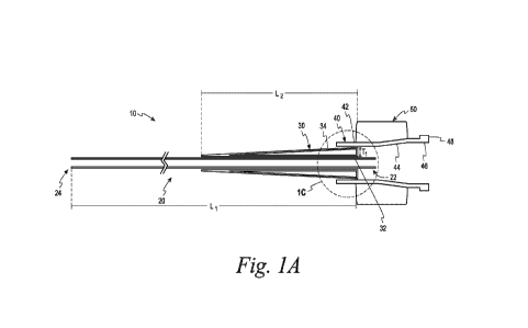
[0045] Referring initially to FIGS. 1A and 1B, a cannula assembly 10 is shown
in a cross-
sectional side view and a front view, respectively, according to one
embodiment. The cross-
hatching has been removed to enhance the clarity of FIG. 1A. The cannula
assemblies of the
present invention are configured to engage with a syringe (e.g., syringe 60
shown in FIG. 4)
in one embodiment. The cannula assemblies assist in delivering liquid products
to areas of
the body including to brain tissue. The cannula assemblies enable more
practical and leak-
resistant connection to a delivery syringe for brain infusions. The cannula
assemblies also
assist in removing liquid or gathering samples from areas of the body
including from brain
tissue. It is contemplated that the cannula assemblies may be used in other
aspects in other
implementations.
[0046] Referring back to FIGS. lA and 1B, the cannula assembly 10 includes a
cannula 20,
polymeric support material 30 and a hub 40. FIG. 1C is an enlarged side view
of area 1C
taken from FIG. 1A with adhesive added. The cannula 20 is a tube in one
embodiment and is
configured to be inserted into a body. The cannula 20 in one embodiment is a
glass fiber
cannula. It is contemplated that the cannula may be made of other materials
such as metals.
Non-limiting examples of metals that can be used in forming the cannula
include stainless
steel and titanium. It is also contemplated that polymeric materials with a
desired stiffness
may be used in forming the cannula.
[0047] The full length of the cannula 20 has been truncated in FIG. 1A for
clarity and, thus, is
not shown to scale. The cannula has a proximal end 22 and a distal end 24. The
distal end 24
is configured to be inserted into a body. The cannula 20 can vary in length,
but typically has
a length Li of from about 0.3 to about 1.5 meters. In one desired embodiment,
the cannula
20 has a length Li of from about 0.75 to about 1.25 meters. In another desired
embodiment,
the cannula 20 has a length Li of from about 0.9 to about 1.1 meters.
[0048] The cannula 20 can vary in diameter, but typically has a diameter D1
(see FIG. 1B) of
from about 0.25 to about 0.5 mm. In one desired embodiment, the cannula 20 has
a diameter
CA 03217202 2023-10-18
WO 2022/231921
PCT/US2022/025609
7
D1 of from about 0.3 to about 0.45 mm. In another desired embodiment, the
cannula 20 has a
diameter D1 of from about 0.3 to about 0.4 mm.
[0049] As shown in FIGS. 1A-1C, the polymeric support material 30 is located
between the
cannula 20 and the hub 40. Specifically, the polymer support material as best
shown in FIG.
1C has an interior surface 32 located adjacent to the cannula 20 and an
exterior surface 34
that is located adjacent to the hub 40. Referring to FIG. 1A, the polymeric
support material
30 is located at or near the proximal end 22 of the cannula 20. As shown in
FIGS. 1A-1C,
the polymeric support material 30 substantially surrounds a portion of the
cannula 20 at or
near the proximal end 22. For example, the polymeric support material
surrounds 70% or
85% of a portion of the cannula at or near the proximal end. In another
embodiment, the
polymeric support material surrounds 90% or 95% of a portion of the cannula at
or near the
proximal end. It is desirable for the polymeric support material 30 of FIGS.
1A-1C to
completely surround a portion of the cannula 20 at or near the proximal end 22
as best shown
in FIG. 1B.
[0050] The polymeric support material 30 assists in preventing or inhibiting
stress risers. A
stress riser is an abrupt change in flexibility likely to increase fractures
of the cannula when
the cannula is made of glass fibers. The polymeric support material 30 assists
in changing
the stress point by the use of distance, which assists in preventing or
inhibiting breakage of
the cannula 20.
[0051] The polymeric support material 30 can vary in length, but typically has
a length L2
(see FIG. 1A) of from about 5 to about 40 cm in length. In one desired
embodiment, the
polymeric support material 30 has a length L2 of from about 10 to about 30 cm.
In another
desired embodiment, the polymeric support material 30 has a length L2 of from
about 10 to
about 20 cm, or from about 15 to about 20 cm.
[0052] The polymeric support material 30 is tapered in one embodiment from the
proximal
end 22 of the cannula 20 towards the distal end 24. Thickness Ti of the
polymeric support
material 30 is greater at or near the proximal end 22 of the cannula 20. The
thickness Ti of
the polymeric support material 30 is from about 1 mm to about 5 mm and, more
specifically,
from about 1.5 mm to about 4 mm, or from about 2 mm to about 4 mm.
[0053] In one embodiment, the polymeric support material 30 includes
polytetrafluoroethylene (PTFE). The polymeric support material may be made of
other
polymeric materials or combinations of polymeric materials. Some other non-
limiting
materials that may be used in forming the polymeric support material include
polyamides,
fluoropolymers, polyolefins, PVC (polyvinyl chlorides), polyimides, PEEK
CA 03217202 2023-10-18
WO 2022/231921
PCT/US2022/025609
8
(polyetheretherketones), or combinations thereof. It is also desirable for the
polymeric
support material to be generally clear or translucent so as to allow
transmission of ultraviolet
(UV) light if an UV adhesive is used. It is also desirable to have the
material forming the
polymeric support material to be compatible with adeno-associated viruses
(AAV) (i.e., AAV
viruses don't adhere to the material).
[0054] The hub 40 as shown in FIGS. 1A-1C is located adjacent to the exterior
surface 34 of
the polymeric support material 30. The hub 40 is configured to assist in
attaching and
securing the cannula 20 and a syringe (e.g., the syringe 60 in FIG. 4). The
hub 40 also
desirably provides a tight seal with a syringe, as will be discussed below,
that assists in
preventing or inhibiting leakage of any liquid material contained within the
syringe or within
the proximal end 22 of the cannula 20. The hub 40 also is desirably configured
to reduce or
effectively eliminate much of the dead space where any liquid could be
unaccounted for or
bubbles to accumulate.
[0055] The hub 40 as shown in FIG. 1A depicts a first generally horizontal
section 42, a
slightly upwardly tapered section 44, and a second generally horizontal
section 46. The
second generally horizontal section 46 includes an outer rim 48. The outer rim
48
strengthens the hub 40.
[0056] In one embodiment, the hub 40 is a Luer-pressure fitting hub. Some
advantages of
using a Luer-pressure fitting hub include ease and security of attachment. It
is contemplated
that other hubs may be used in the cannula assemblies.
[0057] The hub 40 may be made of materials including, but not limited to,
polymeric
materials. Some non-limiting examples of polymeric materials include, but are
not limited to,
polyolefins (e.g., polypropylenes). It is also desirable for the hub to be
generally clear or
translucent so as to allow transmission of UV light if an UV adhesive is used.
It is also
desired to have the material forming the hub to be compatible with adeno-
associated viruses
(AAV).
[0058] The cannula 20, the polymeric support material 30 and the hub 40 are
adhesively
attached in one embodiment. The adhesive may be applied and located within
different areas
to securely attach the cannula 20, the polymeric support material 30 and the
hub 40. The
adhesive is applied on at least one of the cannula, the polymeric support
material, and the
hub. It is contemplated that the adhesive may be applied on two or more of the
cannula, the
polymeric support material, and the hub. Some representative areas are shown
in FIG. 1C
with adhesive 70a-70d. The adhesive areas 70a, 70d are located between the hub
40 and the
polymeric support material 30. The adhesive areas 70b, 70c are located between
the
CA 03217202 2023-10-18
WO 2022/231921
PCT/US2022/025609
9
polymeric support material 30 and the cannula 20. The adhesive permanently and
securely
attaches the cannula 20, the polymeric support material 30 and the hub 40.
[0059] In one embodiment, the adhesive is an UV-sensitive adhesive. In this
embodiment,
the adhesive is typically a liquid adhesive that is cured using UV light. The
surface tension
of the material that the liquid adhesive contacts assists in maintaining the
positioning of the
adhesive before curing. This may be performed in a single step in one method.
In another
method, the curing of the adhesive may be formed in a multi-step process.
[0060] A UV adhesive is an adhesive that typically works on an epoxy resin or
an acrylic
base. One UV adhesive is a radically-initiated UV adhesive based on an
acrylate mixture
(e.g., urethane, cyanoacrylate or silicone). Thus, UV adhesives include, but
are not limited
to, urethane acrylate adhesive compositions, cyanoacrylate adhesive
compositions, and
silicone acrylate adhesive compositions. LIV adhesives based on acrylates are
typically
solvent-free and include one component, Another UV adhesive is a cationicallv-
initiated UV
adhesive based on epoxy resins. LIV adhesives are marked by companies such as
113ondic,
Rapidfix and Dymax.
[0061] To cure, a UV-sensitive adhesive requires a light source. This can come
from pure
sunlight, but also from UV LED lights and UV gas discharge lamps. However, LED
light
sources must be matched to the respective adhesive and are therefore available
in different
wavelengths. A UV-sensitive adhesive usually cures very quickly. For example,
the curing
of a UV-sensitive adhesive can occur between about 1 and about 10 seconds, and
more
specifically, from about I to about 5 seconds, and from about 1 to about 3
seconds.
Typically, the more intense the light source, the faster the curing process.
IN-sensitive
adhesives may be adhesives that cure only when the user exposes it to UV light
of a precisely
defined wavelength.
[0062] The cannula 20, the polymeric support material 30 and the hub 40 are
securely
attached such that an individual cannot easily separate the components from
each other.
Thus, for example, the cannula 20, the polymeric support material 30 and the
hub 40 are not
attached by a press-fit. Thus, the cannula 20, the polymeric support material
30 and the hub
40 are formed in the absence of a press-fit.
[0063] In one embodiment, the cannula assembly is a non-detachable, closed
sterile system.
In one method, the product to be delivered using the cannula assembly does not
contact an
adhesive that is used to securely attach the cannula 20, the polymeric support
material 30 and
the hub 40. Similarly, in another method, fluid or other product to be removed
the product to
be delivered using the cannula assembly does not contact an adhesive that is
used to securely
CA 03217202 2023-10-18
WO 2022/231921
PCT/US2022/025609
attach the cannula 20, the polymeric support material 30 and the hub 40.
[0064] The cannula assembly 10 may further include a winged connection 50
adapted to
tighten the connection between a syringe (e.g., syringe 60 in FIG. 4) and the
remainder of the
cannula assembly 10. In one process, the winged connection 50 may be tightened
by the use
of a thumb and a forefinger. To assist in grasping the winged connection 50,
it may include a
corrugated, concave area to generally correspond with a shape of a thumb or a
finger.
[0065] Referring to FIGS. 2A, 2B, a cannula assembly 110 is shown in a cross-
sectional
side view according to another embodiment. The cross-hatching has been removed
in FIGS.
2A, 2B to enhance the clarity. The cannula assembly 110 includes the cannula
20, the
polymeric support material 30, a hub 140, overlying tubing 180 and the winged
connection
50.
[0066] The hub 140 is the same as the hub 40 described above except for outer
rim 148. The
outer rim 148 strengthens the hub 140 in a similar manner as the outer rim 48
to the hub 40.
The outer rim 148 also includes an external thread formation 148a. The
external thread
formation 148a may be a single thread or a plurality of threads. The external
thread
formation 148a is configured to be securely attached with a component of a
syringe having an
internal thread formation. For example, the external thread formation 148a may
be attached
to a Hamilton connector ring of a syringe. Thus, the external thread formation
148a assists in
securely attaching the cannula assembly 110 with a syringe (e.g., syringe 60
of FIG. 4).
[0067] The overlying tubing 180 is located on an exterior surface 142 of the
hub 140 as
shown in FIGS. 2A, 2B. The overlying tubing 180 in one embodiment is made of a
flexible
material. Non-limiting examples of materials that may be used in forming the
overlying
tubing 180 include, but are not limited to, polytetrafluoroethylene (PTFE).
Some other non-
limiting materials that may be used in forming the overlying tubing include
polyamides,
fluoropolymers, polyolefins, PVC (polyvinyl chlorides), polyimides, PEEK
(polyetheretherketones), or combinations thereof. It is also desirable for the
polymeric
support material to be generally clear or translucent so as to allow
transmission of UV light if
an UV adhesive is used. The overlying tubing 180 is located generally above
the proximal
end 22 of the cannula 20. The overlying tubing 180 assists in absorbing and
spreading the
shear load to prevent or inhibit breakage of the cannula 20.
[0068] The overlying tubing 180 can vary in length, but typically has a length
L3 (see FIG.
2A) of from about 5 to about 25 cm. In one desired embodiment, the overlying
tubing 180
has a length L3 of from about 10 to about 20 cm. In another desired
embodiment, the
overlying support 180 has a length L3 of from about 10 to about 15 cm.
CA 03217202 2023-10-18
WO 2022/231921
PCT/US2022/025609
11
[0069] Referring to FIG. 3, a cannula assembly 210 is shown in a cross-
sectional side view
according to a further embodiment. The cross-hatching has been removed in FIG.
3 to
enhance the clarity. The cannula assembly 210 includes a cannula 20, polymeric
support
material 230, the hub 40 and the winged connection 50. The polymeric support
material 230
assists in preventing or inhibiting stress risers.
[0070] The polymeric support material 230 includes a plurality of polymeric
supporting tube
segments 232, 234, 236, 238, 240 that are successively stacked on top of each
other. The
lengths L4-L8 (see FIG. 3) of each of the plurality of polymeric supporting
tube segments
232, 234, 236, 238, 240 are different. The length L4 of the polymeric
supporting tube
segment 232 is the longest, while the length L8 is the shortest. Each of the
lengths of the
polymeric supporting tube segments 232, 234, 236, 238, 240 gets progressively
shorter. The
length L4 of the polymeric supporting tube segment 232 is similar to the
length Li of the
polymeric support material 30. It is contemplated that the number of polymeric
supporting
tube segments may be greater or lesser in number than depicted in FIG. 3.
[0071] As discussed above, the cannula assemblies are adapted to work in
conjunction with a
syringe for delivering or receiving fluids. One type of syringe that may be
used in
conjunction with the cannula assemblies is shown in FIG. 4 with the syringe
60. The syringe
60 includes a needle 62, a barrel assembly 64, a plunger assembly 66 and a
male termination
68. The needle 62 is typically covered by a nut (not shown) to protect
inadvertent contact
with the needle 62. The syringe 60 may be referred to as a Hamilton syringe.
Referring to
FIG. 4, the syringe 60 is a Hamilton syringe. It is contemplated that other
types of syringes
may be used with the cannula assemblies of the present invention such as, for
example, those
manufactured by Setonic, Trident, Becton Dickenson, and Alibaba.
[0072] Referring to FIGS. 5A, 5B, a cannula assembly and syringe combination
300 is shown
in a cross-sectional view. The cross-hatching has been removed to enhance the
clarity in
FIGS. 5A, 5B. The combination 300 includes the cannula assembly 10 and the
syringe 60
described above. The needle 62 of the syringe is not shown for improved
clarity. To reduce
the dead space, the cannula 20 is extended sufficiently into the hub 40 to
receive the syringe
60. The cannula 20 should extend a sufficient distance past the polymeric
support material
30 such that process tolerances will not allow any potential adhesive to be
applied near an
opening 26 of the proximal end 22 of the cannula 20. The adhesive delivery and
the
processing step with UV light need to be precise to avoid blocking the cannula
or creating
leaks.
[0073] Since the proximal end 22 of the cannula 20 is located inside the lumen
of the male
CA 03217202 2023-10-18
WO 2022/231921
PCT/US2022/025609
12
termination 68 of the syringe 60, there is minimal dead space. As shown in
FIGS. 5A, 5B,
dead space 90, 92 is shown between the male termination 68, the hub 40 and
polymeric
support material 30. The hub 40 also desirably provides a tight seal with the
male
termination 68 of the syringe 60 to assist in preventing or inhibiting leakage
of any liquid
material contained within the syringe or within the proximal end 22 of the
cannula 20.
[0074] It is contemplated that a combination may be formed using the cannula
assemblies
110, 210 with the syringe 60 or with other syringes.
[0075] According to yet another method, a viral vector is delivered to a
central nervous
system of a subject. A cannula assembly and a syringe combination is provided
and includes
the cannula assembly and the syringe. The cannula assembly includes a cannula,
polymeric
support material and a hub. The cannula has a proximal end and a distal end.
The polymeric
support material substantially surrounds a portion of the cannula at or near
the proximal end.
The syringe includes a needle. The hub attaches the cannula assembly and the
syringe. The
polymeric support material is located between the cannula and the hub. The
cannula, the
polymeric support material and the hub are adhesively attached. The viral
vector is provided.
The viral vector is delivered to the central nervous system via the cannula
assembly and the
syringe combination.
[0076] Non-limiting examples of agents and therapeutic devices that may be
delivered
through a cannula assembly and syringe combination (e.g., the cannula assembly
and syringe
combinaii on 300) as described herein include, but are not limited to, chugs,
nanoparticies,
biological agents (e.g., cells, virus, etc.).
[0077] In one embodiment, the vector can be, but is not limited to, a nonviral
vector or a viral
vector. In one embodiment of any aspect, the vector is a DNA or RNA virus. Non-
limiting
examples of a viral vector include an AAV vector, an adenovirus vector, a
lentivirus vector, a
retrovirus vector, a herpesvirus vector, an alphavirus vector, a poxvirus
vector, a baculovirus
vector, and a chimeric virus vector. Non-limiting examples of AAV include
AAV1, AAV2,
AAV3, AAV4, AAV5, AAV6, AAV7, AAV8, AAV9, AAV10, AAV11, AAV12, and any
chimeras thereof In some embodiments, AAV are AAV rhesus monkey serotype (AAV
rh).
Non limiting examples of AAV rh serotypes include AAV rh8, AAV rh10, AAV rh20,
AAV
rh74, AAV rh39, AAV rh43, AAV rh38, AAV rh40, AAV rh2, AAV rh25, AAV rh57, AAV
rh50, AAV rh49, AAV rh58, AAV rh61, AAV rh52, AAV rh53, AAV rh51, AAV rh64,
AAV rh8, AAV rhl, AAV rh62, AAV rh48, AAV rh54, AAV rh55, AAV rh35, AAV rh37,
AAV rh36, AAV rh13, AAV rh32, AAV rh33, and AAV rh34.
[0078] Any viral vector that is known in the art can be used with the cannula
assembly and
CA 03217202 2023-10-18
WO 2022/231921
PCT/US2022/025609
13
syringe combination. Examples of such viral vectors include, but are not
limited to, vectors
derived from: Adenoviridae; Birnaviridae; Bunyaviridae; Caliciviridae;
Capillovirus group;
Carlavirus group; Carmovirus virus group; Group Caulimovirus, Closterovirus
Group;
Commelina yellow mottle virus group; Comovirus virus group; Coronaviridae; PM2
phage
group; Corcicoviridae; Group Cryptic virus; group Cryptovirus; Cucumovirus
virus group
Family ([PHgr]6 phage group); Cysioviridae; Group Carnation ringspot;
Dianthovirus virus
group; Group Broad bean wilt; Fabavirus virus group; Filoviridae;
Flaviviridae; Furovirus
group; Group Germinivirus; Group Giardiavirus; Hepadnaviridae; Herpesviridae;
Hordeivirus virus group; Illarvirus virus group; Inoviridae; Iridoviridae;
Leviviridae;
Lipothrixviridae; Luteovirus group; Marafivirus virus group; Maize chlorotic
dwarf virus
group; icroviridae; Myoviridae; Necrovirus group; Nepovirus virus group;
Nodaviridae;
Orthomyxoviridae; Papovaviridae; Paramyxoviridae; Parsnip yellow fleck virus
group;
Partitiviridae; Parvoviridae; Peaenation mosaic virus group; Phycodnaviridae;
Picornaviridae;
Plasmaviridae; Prodoviridae; Polydnaviridae; Potexvirus group; Potyvirus;
Poxviridae;
Re oviri dae; Retroviridae; Rhabdoviridae; Group Rhizidiovirus; Siphoviridae;
Sobemovirus
group; SSV 1-Type Phages; Tectiviridae; Tenuivirus; Tetraviridae; Group
Tobamovirus;
Group Tobravirus; Togaviridae; Group Tombusvirus; Group Torovirus;
Totiviridae; Group
Tymovirus; and Plant virus satellites.
[0079] An effective amount of a viral vector (e.g., a recombinant viral vector
(rAAV)) is an
amount sufficient to target infect an animal, or target a desired tissue. In
some embodiments,
an effective amount of a viral vector (e.g., a recombinant viral vector
(rAAV)) is an amount
sufficient to produce a stable somatic transgenic animal model. The effective
amount will
depend primarily on factors such as the species, age, weight, health of the
subject, and the
tissue to be targeted, and may thus vary among animal and tissue.
[0080] In some embodiments, a dose of a viral vector (e.g., a recombinant
viral vector
(rAAV)) is administered to a subject no more than once per calendar day (e.g.,
a 24-hour
period). In some embodiments, a dose of viral vector is administered to a
subject no more
than once per 2, 3, 4, 5, 6, or 7 calendar days. In some embodiments, a dose
of viral vector is
administered to a subject no more than once per calendar week (e.g., 7
calendar days). In
some embodiments, a dose of viral vector is administered to a subject no more
than bi-weekly
(e.g., once in a two calendar week period). In some embodiments, a dose of
viral vector is
administered to a subject no more than once per calendar month (e.g., once in
30 calendar
days). In some embodiments, a dose of viral vector is administered to a
subject no more than
once per six calendar months. In some embodiments, a dose of viral vector is
administered to
CA 03217202 2023-10-18
WO 2022/231921
PCT/US2022/025609
14
a subject no more than once per calendar year (e.g., 365 days or 366 days in a
leap year).
[0081] Effective amounts, toxicity, and therapeutic efficacy can be determined
by standard
pharmaceutical procedures in cell cultures or experimental animals, e.g., for
determining the
minimal effective dose and/or maximal tolerated dose. The dosage can vary
depending upon
the dosage form employed and the route of administration utilized. A
therapeutically
effective dose can be estimated initially from cell culture assays. Also, a
dose can be
formulated in animal models to achieve a dosage range between the minimal
effective dose
and the maximal tolerated dose. The effects of any particular dosage can be
monitored by a
suitable bioassay, e.g., assay for neuronal degradation or functionality among
others. The
dosage can be determined by a physician and adjusted, as necessary, to suit
observed effects
of the treatment.
[0082] In a further aspect of the above method, the viral vector is in a
dosage of from about
0.5E9 to about 1.5E9 vg/[11 (from about 0.5E12 to about 1.5E12 vg/mil). The
viral vector
may be in a dosage of from about 0.7E9 to about 1.3E9 vg/i1 (from about 0.7E12
to about
1.3E12 vg/mil). In another embodiment, the viral vector may be in a dosage of
from about
0.7E9 to about 1.1E9 vg/[11 (from about 0.7E12 to about 1.1E12 vg/mil). The
viral vector
may be delivered to a subject. The desired dosage should be in range between a
minimally
effective dose at the low end to a less than a mildly toxic level.
[0083] The dose calculation can be complicated, but is mandated by the tissue
reaction to
products delivered directly into the parenchyma of the striatum or another
part of the brain.
If the concentration is too weak (and the volume too small) there is no
therapeutic effect. If
more concentrated, the product may be effective. If the concentration is too
high, it invokes
an inflammatory reaction and if sufficiently strong, it kills the cells at the
injection site. After
the dosage concentration is determined, the volume of that dilution is
calculated that will be
injected into each of the 4 striatal lobes. In humans and non-human primates
(NHPs), the
volumes are individually measured using MRI (2x caudates and 2x putamens). The
volume
of product to be injected into each lobe is calculated as a percentage of the
measured organ
volume. For example, this percentage can range from about 15% to about 50%. A
higher
percentage may be used (e.g., 35 to 50%) if there is inadequate perfusion into
the target lobes.
Typical healthy volumes for the putamen and caudate in human subjects are
about 3.57 and
about 2.73 cm3 respectively, and about 0.55 and about 0.41 cm3 in NHPs.
[0084] In mice, a standard volume for the striatum may be used. In mice, the
striatum
measures about 20 to about 37 mm'. For example, the volume delivered to a
mouse may be 2
[it or 4 ti.L. In another example, the volume delivered to NHPs would be in a
volume range
CA 03217202 2023-10-18
WO 2022/231921
PCT/US2022/025609
of from about 20 L to about 250 L. In a further example, the volume
delivered to humans
would be in a volume range of from about 140 L to about lmL.
[0085] The dosages are delivered using the cannula assemblies of the present
invention.
Deliveries by a needle, for example, into the parenchyma of the brain requires
overcoming
the static fluid pressure of the tissue. Thus, in one method, very slow rates
of injection are
used initially with two stepped up rates to complete the delivery. This is
generally referred to
as "convection enhanced delivery." it is contemplated that other modified
versions of
delivering, including other three step infusion rates, may be used.
[0086] Viral vectors are delivered to a subject using the cannula assembly and
syringe
combination. For
example, recombinant viral vector preferably suspended in a
physiologically compatible carrier (i.e., in a composition), may be
administered to a subject,
i.e., host animal, such as a human, mouse, rat, cat, dog, sheep, rabbit,
horse, cow, goat, pig,
guinea pig, hamster, chicken, turkey, or a non-human primate (e.g., Macaque).
In some
embodiments, a host animal does not include a human.
[0087] Subjects to which the methods of the instant disclosure are applicable
include
veterinary subjects (e.g., dogs, cats, horses, etc.) and research animal
subjects (e.g., mice,
rats, rabbits, pigs, goats, sheep, primates, etc.), as well as human subjects.
The methods are
applicable to all primates, including simians. In some embodiments, the
methods are applied
to humans. In other embodiments, the methods are applied to non-human
primates.
[0088] Any desired area of a subject may be targeted according to the methods
described
herein. In some instances, the desired area may be tissue including, but not
limited to, a
tissue of endodermal origin, a tissue of ectodermal origin, and a tissue
mesodermal origin.
Neural tissues are typically targeted. In some instances, neural tissues of
the central nervous
system (CNS) may be targeted including, for example, tissues of the brain and
tissues of the
spinal cord. In some instances, neural tissues of the peripheral nervous
system may be
targeted. It is contemplated that other tissue may be targeted according to
the methods
described herein.
[0089] in some instances, the methods may be applied for effective
delivery/localization of
an agent to a region of interest in the mammalian nervous system, including
the central
nervous system or the peripheral nervous system. Essentially any region of
interest of the
nervous system may be targeted according to the methods as described herein
including, but
not limited to, the brain, the spinal cord, the spinal ganglia, etc.
[0090] in some instances, the methods may be applied for effective
delivery/localization of
an agent to a refj,on of interest in the mammalian brain. :Essentially any
region. of interest of
CA 03217202 2023-10-18
WO 2022/231921
PCT/US2022/025609
16
the brain may be targeted according to the methods as described herein.
[0091] Viral vectors described herein can be directly injected, into any
region of the brain,
such as, for example, occipital lobe, temporal lobe, parietal lobe, frontal
lobe, cerebral cortex,
cerebellum, hypothalamus, thalamus, pituitary gland, pineal gland, amygdala,
hippocampus
and the mid-brain.
[0092] In some instances, one or more brain lobes or a particular area within
a brain lobe may
be targeted including, but not limited to, the frontal lobe (either the entire
frontal lobe or
portions thereof including, but not limited to, Superior Frontal, Rostra'
Middle Frontal,
Caudal Middle Frontal, Pars Operculatis, Pars Triangular's, and Pars
Orbitalis, Lateral
Orbitofrontal, Medial Orbitofrontal, Precentral, Paracentral, Frontal Pole,
combinations
thereof, and the like), parietal lobe (either the entire parietal lobe or
portions thereof
including, hut not: limited to, Superior Parietal, Inferior Parietal,
Supramar,ginal, .Postcentral,
Precuneus, combinations thereof, and the like), temporal lobe (either the
entire temporal lobe
or portions thereof including, but not limited to, Superior Temporal, Middle
Temporal,
Inferior Temporal, Banks of the Superior Temporal Sulcus, Fusifom, Transverse
Temporal,
Entorhin.al, Temporal Pole, Parahippocampal, combinations thereof, and the
like) and
occipital lobe (either the entire occipital lobe or portions thereof
including, but not limited to,
Lateral Occipital, Lingual, Cuneus, Pericalcarine, combinations thereof, and
the like).
[0093] In some instances, one or more brain structures or a particular area
within a brain
structure may be targeted including, but not limited to, Hindbrain structures
(e.g.,
My el encephal on structures (e.g., Medulla oblongata, Medullary pyramids,
Olivary body,
Inferior olivary nucleus, Respiratory center, Cuneate nucleus, Gracile
nucleus, Intercalated
nucleus, Medullary cranial nerve nuclei, Inferior salivatory nucleus, Nucleus
ambiguous,
Dorsal nucleus of vagus nerve, Hypoglossal nucleus, Solitary nucleus, etc.),
Metencephalon
structures (e.g., Pons, Pontine cranial nerve nuclei, chief or pontine nucleus
of the trigeminal
nerve sensory nucleus (V), Motor nucleus for the trigeminal nerve (V),
Abducens nucleus
(VI), Facial nerve nucleus (VII), vestibulocochlear nuclei (vestibular nuclei
and cochlear
nuclei) (VIII), Superior salivatory nucleus, Pontine tegmentum, Respiratory
centres,
Pneumotaxic centre, Apneustic centre, Pontine micturition center (Barrington's
nucleus),
Locus coeruleus, Pedunculopontine nucleus, Laterodorsal tegmental nucleus,
Tegmental
pontine reticular nucleus, Superior olivary complex, Paramedian pontine
reticular formation,
Cerebellar peduncles, Superior cerebellar peduncle, Middle cerebellar
peduncle, Inferior
cerebellar peduncle, Fourth ventricle, Cerebellum, Cerebellar vermis,
Cerebellar
hemispheres, Anterior lobe, Posterior lobe, Flocculonodular lobe, Cerebellar
nuclei, Fastigial
CA 03217202 2023-10-18
WO 2022/231921
PCT/US2022/025609
17
nucleus, Interposed nucleus, Globose nucleus, Emboliform nucleus, Dentate
nucleus, etc.)),
Midbrain structures (e.g., Tectum, Corpora quadrigemina, inferior colliculi,
superior colliculi,
Pretectum, Tegmentum, Periaqueductal gray, Parabrachial area, Medial
parabrachial nucleus,
Lateral parabrachial nucleus, Subparabrachial nucleus (Kolliker-Fuse nucleus),
Rostral
interstitial nucleus of medial longitudinal fasciculus, Midbrain reticular
formation, Dorsal
raphe nucleus, Red nucleus, Ventral tegmental area, Substantia nigra, Pars
compacta, Pars
reticulata, Interpeduncular nucleus, Cerebral peduncle, Crus cerebri,
Mesencephalic cranial
nerve nuclei, Oculomotor nucleus (Ill), Trochlear nucleus (IV), Mesencephalic
duct (cerebral
aqueduct, aqueduct of Sylvius), etc.), Forebrain structures (e.g.,
Diencephalon, Epithalamus
structures (e.g., Pineal body, Habenular nuclei, Stria medullares, Taenia
thalami, etc.) Third
ventricle, Thalamus structures (e.g., Anterior nuclear group, Anteroventral
nucleus (aka
ventral anterior nucleus), Anterodorsal nucleus, Anteromedial nucleus, Medial
nuclear group,
Medial dorsal nucleus, Midline nuclear group, Paratenial nucleus, Reuniens
nucleus,
Rhomboidal nucleus, Intralaminar nuclear group, Centromedial nucleus,
Parafascicular
nucleus, Paracentral nucleus, Central lateral nucleus, Central medial nucleus,
Lateral nuclear
group, Lateral dorsal nucleus, Lateral posterior nucleus, Pulvinar, Ventral
nuclear group,
Ventral anterior nucleus, Ventral lateral nucleus, Ventral posterior nucleus,
Ventral posterior
lateral nucleus, Ventral posterior medial nucleus, Metathalamus, Medial
geniculate body,
Lateral geniculate body, Thalamic reticular nucleus, etc.), Hypothalamus
structures (e.g.,
Anterior, Medial area, Parts of preoptic area, Medial preoptic nucleus,
Suprachiasmatic
nucleus, Paraventricular nucleus, Supraoptic nucleus (mainly), Anterior
hypothalamic
nucleus, Lateral area, Parts of preoptic area, Lateral preoptic nucleus,
Anterior part of Lateral
nucleus, Part of supraoptic nucleus, Other nuclei of preoptic area, median
preoptic nucleus,
periventricular preoptic nucleus, Tuberal, Medial area, Dorsomedial
hypothalamic nucleus,
Ventromedial nucleus, Arcuate nucleus, Lateral area, Tuberal part of Lateral
nucleus, Lateral
tuberal nuclei, Posterior, Medial area, Mammillary nuclei (part of mammillary
bodies),
Posterior nucleus, Lateral area, Posterior part of Lateral nucleus, Optic
chiasm, Subfornical
organ, Periventricular nucleus, Pituitary stalk, Tuber cinereum, Tuberal
nucleus,
Tuberomammillary nucleus, Tuberal region, Mammillary bodies, Mammillary
nucleus, etc.),
Subthalamus structures (e.g., Thalamic nucleus, Zona incerta, etc.), Pituitary
gland structures
(e.g., neurohypophysis, Pars intermedia (Intermediate Lobe), adenohypophysis,
etc.),
Telencephalon structures, white matter structures (e.g., Corona radiata,
Internal capsule,
External capsule, Extreme capsule, Arcuate fasciculus, Uncinate fasciculus,
Perforant Path,
etc.), Subcortical structures (e.g., Hippocampus (Medial Temporal Lobe),
Dentate gyrus,
CA 03217202 2023-10-18
WO 2022/231921
PCT/US2022/025609
18
Cornu ammonis (CA fields), Cornu ammonis area 1, Cornu ammonis area 2, Cornu
ammonis
area 3, Cornu ammonis area 4, Amygdala (limbic system) (limbic lobe), Central
nucleus
(autonomic nervous system), Medial nucleus (accessory olfactory system),
Cortical and
basomedial nuclei (main olfactory system), Lateral[disambiguation needed] and
basolateral
nuclei (frontotemporal cortical system), Claustrum, Basal ganglia, Striatum,
Dorsal striatum
(aka neostriatum), Putamen, Caudate nucleus, Ventral striatum, Nucleus
accumbens,
Olfactory tubercle, Globus pallidus (forms nucleus lentiformis with putamen),
Subthalamic
nucleus, Basal forebrain, Anterior perforated substance, Substantia
innominata, Nucleus
basalis, Diagonal band of Broca, Medial septal nuclei, etc.), Rhinencephalon
structures (e.g.,
Olfactory bulb, Piriform cortex, Anterior olfactory nucleus, Olfactory tract,
Anterior
commissure, Uncus, etc.), Cerebral cortex structures (e.g., Frontal lobe,
Cortex, Primary
motor cortex (Precentral gyms, MO, Supplementary motor cortex, Premotor
cortex,
Prefrontal cortex, Gyri, Superior frontal gyms, Middle frontal gyms, Inferior
frontal gyms,
Brodmann areas: 4, 6, 8, 9, 10, 11, 12, 24, 25, 32, 33, 44, 45, 46, 47,
Parietal lobe, Cortex,
Primary somatosensory cortex (Si), Secondary somatosensory cortex (S2),
Posterior parietal
cortex, Gyri, Postcentral gyms (Primary somesthetic area), Other, Precuneus,
Brodmann
areas 1, 2, 3 (Primary somesthetic area); 5, 7, 23, 26, 29, 31, 39, 40,
Occipital lobe, Cortex,
Primary visual cortex (V1), V2, V3, V4, V5/MT, Gyri, Lateral occipital gyms,
Cuneus,
Brodmann areas 17 (V1, primary visual cortex); 18, 19, Temporal lobe, Cortex,
Primary
auditory cortex (Al), secondary auditory cortex (A2), Inferior temporal
cortex, Posterior
inferior temporal cortex, Superior temporal gyms, Middle temporal gyms,
Inferior temporal
gyms, Entorhinal Cortex, Perirhinal Cortex, Parahippocampal gyms, Fusiform
gyms,
Brodmann areas: 9, 20, 21, 22, 27, 34, 35, 36, 37, 38, 41, 42, Medial superior
temporal area
(MST), Insular cortex, Cingulate cortex, Anterior cingulate, Posterior
cingulate, Retrosplenial
cortex, Indusium griseum, Subgenual area 25, and Brodmann areas 23, 24; 26,
29, 30
(retrosplenial areas); 31, 32, etc.)).
[0094] in some instances, one or more neural pathways or a particular portion
of a neural
pathway may be targeted including, but not limited to, neural pathways of
those brain lobes
and structures described above, Superior Longitudinal Fasciculus, Arcuate
faseiculus,
Cerebral peduncle, Corpus catiostrm, Pyramidal or cord cospinal tract, Major
dopamine
pathways dopamine system, Mesocortical pathway, Mesolimbic pathway,
Nigrostriatal
pathway, Tuberoinfundibular pathway, Seroionin Pathways serotonin system,
Raphe Nuclei,
Norepinephrine Pathways, and Locus coeruleus, etc.
[0095] Diseased neural tissues that may be targeted include, but are not
limited to, neural
CA 03217202 2023-10-18
WO 2022/231921
PCT/US2022/025609
19
tissue disease due to one or more of meningitis, encephalitis, multiple
sclerosis (MS), stroke,
brain tumors, epilepsy, A zl ei s
disease, AIDS-related dementia, Parkinson's disease and
Huntington's disease.
[0096] Delivery of the compositions to a mammalian subject may be by, for
example, any
known means of delivering to a desire site, e.g., the central nervous system
(CNS). It may be
desirable to deliver the composition to the CNS of a subject. By "CNS" is
meant all cells and
tissue of the brain and spinal cord of a vertebrate. Thus, the term includes,
but is not limited
to, neuronal cells, glial cells, astrocytes, cerebrospinal fluid (CSF),
interstitial spaces, bone,
cartilage and the like. Any composition described herein may be delivered
directly to the
CNS or brain by injection into, for example, the ventricular region, as well
as to the striatum
(e.g., the caudate nucleus or putamen of the striatum), spinal cord and
neuromuscular
junction, or cerebellar lobule, with a needle, catheter or related device,
using neurosurgical
techniques known in the art, such as by stereotactic injection. In some
embodiments,
compositions as described in the disclosure are administered by intravenous
injection. In
some embodiments, compositions as described in the disclosure are administered
by
intraspinal injection. In some embodiments, compositions as described in the
disclosure are
administered by intracerebro ventricular injection. In some embodiments,
compositions are
administered by intracerebral injection. In some embodiments, compositions are
administered
by intrathecal injection. In some embodiments, compositions are administered
by intrastriatal
injection. In some embodiments, compositions are delivered by intracranial
injection. In
some embodiments, compositions are delivered by cisterna magna injection. In
some
embodiments, compositions are delivered by cerebral lateral ventricle
injection.
[0097] The CNS includes, but is not limited to, certain regions of the CNS,
neural pathways,
somatosensory systems, visual systems, auditory systems, nerves, neuro
endocrine systems,
neuro vascular systems, brain neurotransmitter systems, and dural meningeal
system.
[0098] Exemplary regions of the CNS include, but are not limited to,
Myelencephalon;
Medulla oblongata; Medullary pyramids; Olivary body; Inferior olivary nucleus;
Rostral
ventrolateral medulla; Caudal ventrolateral medulla; Solitary nucleus (Nucleus
of the solitary
tract); Respiratory center-Respiratory groups Dorsal respiratory group;
Ventral respiratory
group or Apneustic centre Pre-Botzinger complex; Botzinger complex;
Retrotrapezoid
nucleus; Nucleus retrofaci al i s; Nucleus retroambiguus; Nucleus para-
ambiguus; Paramedian
reticular nucleus; Gigantocellular reticular nucleus; Parafacial zone; Cuneate
nucleus; Gracile
nucleus; Perihypoglossal nuclei; Intercalated nucleus; Prepositus nucleus;
Sublingual
nucleus; Area postrema; Medullary cranial nerve nuclei; Inferior salivatory
nucleus; Nucleus
CA 03217202 2023-10-18
WO 2022/231921
PCT/US2022/025609
ambiguus; Dorsal nucleus of vagus nerve; Hypoglossal nucleus; Chemoreceptor
trigger zone;
Metencephalon; Pons; Pontine nuclei; Pontine cranial nerve nuclei; Chief or
pontine nucleus
of the trigeminal nerve sensory nucleus, Motor nucleus for the trigeminal
nerve; Abducens
nucleus (VI); Facial nerve nucleus (VII); Vestibulocochlear nuclei (vestibular
nuclei and
cochlear nuclei) (VIII); Superior salivatory nucleus; Pontine tegmentum;
Pontine micturition
center (Barrington's nucleus); Locus coeruleus; Pedunculopontine nucleus;
Laterodorsal
tegmental nucleus; Tegmental pontine reticular nucleus; Nucleus incertus;
Parabrachial area;
Medial parabrachial nucleus; Lateral parabrachial nucleus; Subparabrachial
nucleus
(K011iker-Fuse nucleus); Pontine respiratory group, Superior olivary complex;
Medial
superior olive; Lateral superior olive; Medial nucleus of the trapezoid body;
Paramedian
pontine reticular formation; Parvocellular reticular nucleus; Caudal pontine
reticular nucleus;
Cerebellar peduncles, Superior cerebellar peduncle; Middle cerebellar
peduncle; Inferior
cerebellar peduncle; Fourth ventricle; Cerebellum Cerebellar vermis;
Cerebellar hemispheres;
Anterior lobe; Posterior lobe; Flocculonodular lobe; Cerebellar nuclei;
Fastigial nucleus;
Interposed nucleus; Globose nucleus; Emboliform nucleus; Dentate nucleus;
Midbrain
(mesencephalon); Tectum Corpora quadrigemina; Inferior colliculi; Superior
colliculi;
Pretectum; Tegmentum Periaqueductal gray; Rostral interstitial nucleus of
medial
longitudinal fasciculus; Midbrain reticular formation; Dorsal raphe nucleus;
Red nucleus;
Ventral tegmental area; Parabrachial pigmented nucleus; Paranigral nucleus;
Rostromedial
tegmental nucleus; Caudal linear nucleus; Rostral linear nucleus of the raphe;
Interfascicular
nucleus; Substantia nigra; Pars compacta; Pars reticulata; Interpeduncular
nucleus; Cerebral
peduncle; Crus cerebri; Mesencephalic cranial nerve nuclei; Oculomotor nucleus
(III);
Edinger-Westphal nucleus; Trochlear nucleus (IV); Mesencephalic duct (cerebral
aqueduct,
aqueduct of Sylvius); Forebrain (prosencephalon); Diencephalon; Epithalamus;
Pineal body
(pineal gland); Habenular nuclei; Stria medullaris; Taenia thalami; Third
ventricle;
Subcommissural organ; Thalamus; Anterior nuclear group; Anteroventral nucleus
(a.k.a.
ventral anterior nucleus); Anterodorsal nucleus; Anteromedial nucleus; Medial
nuclear
group; Medial dorsal nucleus; Midline nuclear group; Paratenial nucleus;
Reuniens nucleus;
Rhomboidal nucleus; Intralaminar nuclear group; Centrom edi an nucleus;
Parafascicular
nucleus; Paracentral nucleus; Central lateral nucleus; Lateral nuclear group;
Lateral dorsal
nucleus; Lateral posterior nucleus; Pulvinar; Ventral nuclear group Ventral
anterior nucleus;
Ventral lateral nucleus; Ventral posterior nucleus; Ventral posterior lateral
nucleus; Ventral
posterior medial nucleus; Metathalamus; Medial geni cul ate body; Lateral geni
cul ate body;
Thalamic reticular nucleus; Hypothalamus (limbic system) (HPA axis); Anterior
Medial area
CA 03217202 2023-10-18
WO 2022/231921
PCT/US2022/025609
21
Parts of preoptic area; Medial preoptic nucleus INAH 1; INAH 2; INAH 3; INAH
4; Median
preoptic nucleus; Suprachiasmatic nucleus; Paraventricular nucleus; Supraoptic
nucleus
(mainly); Anterior hypothalamic nucleus; Lateral area; Parts of preoptic area;
Lateral preoptic
nucleus; Anterior part of Lateral nucleus; Part of supraoptic nucleus; Other
nuclei of preoptic
area; Median preoptic nucleus; Periventricular preoptic nucleus; Tuberal
Medial area;
Dorsomedial hypothalamic nucleus; Ventromedial nucleus; Arcuate nucleus,
Lateral area
Tuberal part of Lateral nucleus; Lateral tuberal nuclei; Posterior Medial area
Mammillary
nuclei (part of mammillary bodies); Posterior nucleus; Lateral area Posterior
part of Lateral
nucleus, Surface Median eminence; Mammillary bodies; Pituitary stalk
(infundibulum);
Optic chi asm ; Sub forni c al organ; Periventricular nucleus; Tuber cinereum;
Tuberal nucleus;
Tuberomammillary nucleus; Tuberal region; Mammillary nucleus; Subthalamus (HPA
axis);
Subthalamic nucleus; Zona incerta; Pituitary gland (HPA axis);
Neurohypophysis, Pars
intermedia (Intermediate Lobe); Adenohypophysis; Telencephalon (cerebrum);
Cerebral
hemispheres; White matter; Centrum semiovale; Corona radiata; Internal
capsule; External
capsule; Extreme capsule; Sub corti c al ; Hipp ocampu s (Medial Temporal
Lobe); Dentate
gyms; Cornu ammonis (CA fields); Cornu ammonis area 1 (CA1); Cornu ammonis
area 2
(CA2); Cornu ammonis area 3 (CA3); Cornu ammonis area 4 (CA4); Amygdala
(limbic
system) (limbic lobe); Central nucleus (autonomic nervous system); Medial
nucleus
(accessory olfactory system); Cortical and basomedial nuclei (main olfactory
system); Lateral
and basolateral nuclei (frontotemporal cortical system); Extended amygdala;
Stria terminalis
Bed nucleus of the stria terminalis; Claustrum; Basal ganglia; Striatum Dorsal
striatum (a.k.a.
neostriatum); Putamen; Caudate nucleus; Ventral striatum; Nucleus accumbens;
Olfactory
tubercle; Globus pallidus (forms nucleus lentiformis with putamen); Ventral
pallidum;
Subthalamic nucleus; Basal forebrain; Anterior perforated substance;
Substantia innominata;
Nucleus basalis; Diagonal band of Broca; Septal nuclei; Medial septal nuclei;
Lamina
terminalis; Vascular organ of lamina terminalis; Rhinencephalon (paleocortex);
Olfactory
bulb; Olfactory tract; Anterior olfactory nucleus; Piriform cortex; Anterior
commissure;
Uncus; Periamygdaloid cortex; Cerebral cortex (neocortex); Frontal lobe;
Cortex Primary
motor cortex (Precentral gyms, MO; Supplementary motor cortex; Premotor
cortex;
Prefrontal cortex; Orbitofrontal cortex; Dorsolateral prefrontal cortex; Gyri
Superior frontal
gyms; Middle frontal gyms; Inferior frontal gyms; Brodmann areas: 4, 6, 8, 9,
10, 11, 12, 24,
25, 32, 33, 44, 45, 46, 47; Parietal lobe Cortex Primary somatosensory cortex
(51);
Secondary somatosensory cortex (S2); Posterior parietal cortex; Gyri
Postcentral gyms
(Primary somesthetic area); Brodmann areas 1, 2, 3 (Primary somesthetic area);
5, 7, 23, 26,
CA 03217202 2023-10-18
WO 2022/231921
PCT/US2022/025609
22
29, 31, 39, 40; Occipital lobe Cortex Primary visual cortex (V1), V2, V3, V4,
V5/MT; Gyri
Lateral occipital gyms; Brodmann areas 17 (V1, primary visual cortex); 18, 19;
Temporal
lobe Cortex Primary auditory cortex (Al); Secondary auditory cortex (A2);
Inferior temporal
cortex; Posterior inferior temporal cortex; Gyri Superior temporal gyms;
Middle temporal
gyms; Inferior temporal gyms; Entorhinal cortex; Perirhinal cortex;
Parahippocampal gyms;
Fusiform gyms; Brodmann areas: 20, 21, 22, 27, 34, 35, 36, 37, 38, 41, 42,
Insular cortex;
Cingulate cortex Anterior cingulate; Posterior cingulate; Retrosplenial
cortex; Indusium
griseum; Subgenual area 25; and Brodmann areas 23, 24; 26, 29, 30
(retrosplenial areas); 31,
and 32.
[0099] Exemplary neural pathways include, but are not limited to, Superior
longitudinal
fasciculus Arcuate fasciculus; Uncinate fasciculus; Perforant pathway;
Thalamocortical
radiations; Corpus callosum; Anterior commissure; Amygdalofugal pathway;
Interthalamic
adhesion; Posterior commi s sure ; Habenular commissure; Fornix;
Mammillotegmental;
fasciculus; Incertohypothalamic pathway; Cerebral peduncle; Medial forebrain
bundle;
Medial longitudinal fasciculus; Myoclonic triangle; Solitary tract; Major
dopaminergic
pathways from dopaminergic cell groups; Mesocortical pathway; Mesolimbic
pathway;
Nigrostriatal pathway; Tuberoinfundibular pathway; Serotonergic pathways Raphe
Nuclei;
Norepinephrine Pathways Locus coeruleus and other noradrenergic cell groups;
Epinephrine
pathways from adrenergic cell groups; Glutamate and acetylcholine pathways
from
mesopontine nuclei; Motor systems / Descending fibers; Extrapyramidal system;
Pyramidal
tract; Corticospinal tract; or Cerebrospinal fibers; Lateral corticospinal
tract; Anterior
corticospinal tract; Corticopontine fibers; Frontopontine fibers;
Temporopontine fibers;
Corticobulbar tract; Corticomesencephalic tract; Tectospinal tract;
Interstitiospinal tract;
Rubrospinal tract; Rubro-olivary tract; Olivocerebellar tract; Olivospinal
tract;
Vestibulospinal tract; Lateral vestibulospinal tract; Medial vestibulospinal
tract;
Reticulospinal tract; Lateral raphespinal tract; Alpha system; and Gamma
system.
[0100] Exemplary somatosensory systems include, but are not limited to, Dorsal
column¨
medial lemniscus pathway Gracile fasciculus; Cuneate fasciculus; Medial
lemniscus;
Spinothalamic tract; Lateral spinothalamic tract; Anterior spinothalamic
tract;
Spinomesencephalic tract; Spinocerebellar tract; Spino-olivary tract; and
Spinoreticular tract.
[0101] Exemplary visual systems include, but are not limited to, Optic tract;
Optic radiation;
Retinohypothalamic and tract.
[0102] Exemplary auditory systems include, but are not limited to, Medullary
striae of fourth
ventricle; Trapezoid body; and Lateral lemniscus.
CA 03217202 2023-10-18
WO 2022/231921
PCT/US2022/025609
23
[0103] Exemplary nerves include, but are not limited to, Brain stem Cranial
nerves Terminal
(0); Olfactory (I); Optic (II); Oculomotor (III); Trochlear (IV); Trigeminal
(V); Abducens
(VI); Facial (VII); Vestibulocochlear (VIII); Glossopharyngeal (IX); Vagus(X);
Accessory
(XI); and Hypogl os sal (XII).
[0104] Exemplary neuro endocrine systems include, but are not limited to,
Hypothalamic-
pituitary hormones; HPA axis; HPG axis; FIPT axis; and GHRH ¨ GH.
[0105] Exemplary neuro vascular systems include, but are not limited to,
Middle cerebral
artery; Posterior cerebral artery; Anterior cerebral artery; Vertebral artery;
Basilar artery;
Circle of Willis (arterial system); Blood-brain barrier; Glymphatic system;
Venous systems;
and Circumventricular organs.
101061 Exemplary brain neurotransmitter systems include, but are not limited
to,
Noradrenaline system; Dopamine system; Serotonin system; Cholinergic system;
GABA;
Neuropeptides Opioid peptides; Endorphins; Enkephalins; Dynorphins; Oxytocin;
and
Substance P.
[0107] Exemplary dural meningeal system include, but are not limited to, Brain-
cerebrospinal
fluid barrier; Meningeal coverings Dura mater; Arachnoid mater; Pia mater;
Epidural space;
Subdural space; Subarachnoid space Arachnoid septum; Superior cistern; Cistern
of lamina
terminalis; Chiasmatic cistern; Interpeduncular cistern; Pontine cistern;
Cisterna magna;
Spinal subarachnoid space; Ventricular system; Cerebrospinal fluid; Third
ventricle; Fourth
ventricle; Lateral ventricles Angular bundle; Anterior horn; Body of lateral
ventricle; Inferior
horn; Posterior horn Calcar avis; and Subventricular zone.
[0108] The "PNS" refers to the nerves and ganglia outside the brain and spinal
cord. The
main function of the PNS is to connect the CNS to the limbs and organs,
essentially serving
as a relay between the brain and spinal cord and the rest of the body. Unlike
the CNS, the
PNS is not protected by the vertebral column and skull, or by the blood¨brain
barrier, which
leaves it exposed to, e.g., toxins and mechanical injuries.
[0109] The peripheral nervous system (PNS) is divided into the somatic nervous
system and
the autonomic nervous system. In the somatic nervous system, the cranial
nerves are part of
the PNS with the exception of the optic nerve (cranial nerve II), along with
the retina. The
second cranial nerve is not a true peripheral nerve but a tract of the
diencephalon. Cranial
nerve ganglia originated in the CNS. However, the remaining ten cranial nerve
axons extend
beyond the brain and are therefore considered part of the PNS. The autonomic
nervous
system exerts involuntary control over smooth muscle and glands. The
connection between
CNS and organs allows the system to be in two different functional states:
sympathetic and
CA 03217202 2023-10-18
WO 2022/231921
PCT/US2022/025609
24
parasympathetic.
[0110] As used herein, "neurological disease or disorder" can refer to any
disease, disorder,
or condition affecting or associated with the nervous system, i.e., those that
affect the central
nervous system (brain and spinal cord), the peripheral nervous system
(peripheral nerves and
cranial nerves), and the autonomic nervous system (parts of which are located
in both central
and peripheral nervous systems). More than 600 neurological diseases have been
identified
in humans. By way of non-limiting examples, the neurological disease or
disorder includes
Alzheimer's disease, Parkinson's disease, Huntington's disease, Canavan
disease, Leigh's
disease, spinal cerebral ataxia, Krabbe's disease, Batten's disease, Refsum
disease, Tourette
syndrome, primary lateral sclerosis, amyotrophic lateral sclerosis,
progressive muscular
atrophy, Pick's disease, muscular dystrophy, multiple sclerosis, myasthenia
gravis,
Binswanger's disease, trauma due to spinal cord or head injury, ophthalmic
diseases and
disorders, Tay-Sachs disease, Lesch-Nyan disease, epilepsy, cerebral infarcts,
depression,
bipolar affective disorder, persistent affective disorder, secondary mood
disorder,
schizophrenia, drug dependency, neuroses, psychosis, dementia, paranoia,
attention deficit
disorder, a psychosexual disorder, a sleeping disorder, a pain disorder,
and/or a eating or
weight disorder. In some embodiments, the neurological disease or disorder is
a central
nervous system (CNS) disease or disorder, e.g., Huntington's disease,
Parkinson's disease, or
Alzheimer' s disease.
[0111] In one aspect, the invention provides methods for treating neurological
disorders
involving the cortex, referred to herein as "cortical neurological disorders."
The methods
involve delivery of viral vectors described herein, or composition thereof to
the CNS or PNS.
Preferred cortical neurological disorders are those that involve large areas
of the cortex,
preferably more than one functional area of the cortex, preferably more than
one lobe of the
cortex, and up to and including the entire cortex. Preferred cortical
neurological disorders
include, but are not limited to, traumatic brain injury; stroke; enzymatic
dysfunction
disorders; psychiatric disorders, including post-traumatic stress syndrome;
neurodegenerative
diseases, including Huntington's disease, Parkinson's disease and Alzheimer's
disease;
epilepsy; and cognitive disorders, including dementias, autism, and
depression. Preferred
enzymatic dysfunction disorders include, but are not limited to,
leukodystrophies, including
Canavan's disease, and lysosomal storage diseases (LSD), including Niemann-
Pick disease,
Gaucher disease, Batten disease, Fabry disease and Pompe disease.
[0112] "Cortical neurological disorder", as used herein, refers to a
neurological disorder
involving the cortex. Cortical neurological disorders are neurological
disorders that: (i)
CA 03217202 2023-10-18
WO 2022/231921
PCT/US2022/025609
involve a population of cells in the cortex that is directly anatomically
connected to the
thalamus, and/or (ii) involve a population of cells that is directly
anatomically connected to
the cortical cell population in (i).
[0113] Preferred cortical neurological disorders are those that involve large
areas of the
cortex, preferably more than one functional area of the cortex, preferably
more than one lobe
of the cortex, and up to and including the entire cortex. Preferred cortical
neurological
disorders include, but are not limited to, traumatic brain injury; stroke;
enzymatic dysfunction
disorders; psychiatric disorders, including post-traumatic stress syndrome;
neurodegenerative
diseases, including Huntington's disease, Parkinson's disease and Alzheimer's
disease;
epilepsy; and cognitive disorders, including dementias, autism, and
depression. Preferred
enzymatic dysfunction disorders include, but are not limited to
leukodystrophies, including
Canavan's disease, and lysosomal storage diseases (LSD), including Niemann-
Pick disease,
Gaucher disease, Batten disease, Fabry disease and Pompe disease. This list of
disorders is
exemplary and non-limiting.
[0114] It will be apparent to the reasonably skilled artisan which
neurological disorders are
suitable for treatment by the present methods based on cortical pathology and
neuroanatomical connectivity. "Cortex" as used herein refers to the cerebral
cortex. In some
embodiments, the neurological disease or disorder is a CNS disease or
disorder, e.g.,
Huntington's disease, Parkinson's disease, or Alzheimer's disease. In some
embodiments, the
neurological disease or disorder is a PNS disease or disorder, e.g.,
peripheral neuropathy.
[0115] According to one method, a viral vector is delivered to a central
nervous system of a
subject. The method includes providing a cannula assembly and a syringe
combination
including the cannula assembly and the syringe. The cannula assembly includes
a cannula,
polymeric support material and a hub. The cannula has a proximal end and a
distal end. The
polymeric support material substantially surrounds a portion of the cannula at
or near the
proximal end. The syringe includes a needle. The hub attaches the cannula
assembly and the
syringe. The polymeric support material is located between the cannula and the
hub. The
cannula, the polymeric support material and the hub are adhesively attached.
The viral vector
is provided and delivered to the central nervous system via the cannula
assembly and the
syringe combination.
[0116] According to another method, a neurological disorder is treated in a
subject in need
thereof. The method includes providing a cannula assembly and a syringe
combination
including the cannula assembly and the syringe. The cannula assembly includes
a cannula,
polymeric support material and a hub. The cannula has a proximal end and a
distal end. The
CA 03217202 2023-10-18
WO 2022/231921
PCT/US2022/025609
26
polymeric support material substantially surrounds a portion of the cannula at
or near the
proximal end. The syringe includes a needle. The hub attaches the cannula
assembly and the
syringe. The polymeric support material is located between the cannula and the
hub. The
cannula, the polymeric support material and the hub are adhesively attached. A
viral vector
is provided and is delivered to the central nervous system via the cannula
assembly and the
syringe combination. The neurological disorder is treated using the delivered
viral vector to
the central nervous system.
[0117] The neurological disorder in this method includes, but is not limited
to, meningitis,
encephali us, multiple sclerosis (MS stroke, brain tumors, epilepsyAlzliei in
or' ,3 disease,
AID S -re ated dementia, Parkinson's disease or Huntington's disease.
[0118] In the present invention, the viral vector comprises therapeutic
nucleic acid (e.g.,
DNA or RNA) within its genome. The rAAV can comprise any nucleic acid having
therapeutic benefit. In some embodiments, the therapeutic nucleic acid is non-
coding. For
example, the therapeutic nucleic acid is non-coding RNA. Non-limiting examples
of non-
coding RNA are shRNA, siRNA, miRNA. In other embodiments, the therapeutic
nucleic
acid encodes therapeutic transgenes.
[0119] Non-limiting examples of therapeutic transgenes that can provide a
therapeutic benefit
for a disease or disorder of the CNS include CYP46A1 and HTT (For
Huntington's), AADC
and GDNF (for Parkinson's), GLB1 (for GM1), GDNF (for MSA), ASM (for Niemann-
Pick), CYP46A1 (for Alzheimer's, ALS, MS and epilepsy), and UBE3A (for
Angelman's). In some embodiments, the polypeptide-encoding transgene encodes
an
antibody or antigen-binding fragment thereof. Approaches for the treatment of
CNS diseases
or disorders can also: target metabolic pathways (e.g., CYP46A1 to clear
protein-lipid rafts or
protein aggregates for Huntington's, Parkinson's, ALS and Alzheimer's; similar
approaches
can also target synuclein and/or tau); use miRNA, shRNA and/or ribozyme
meditated
knockdown of undesirable mRNA transcripts (e.g., mHTT or HTT for Huntington's
or ATS
knockdown for Angelman' s); use transgene expression for gene replacement
(e.g., for
restoring normal splicing by adding MBNL2 or SFRF6 in Huntington's, as well as
more
traditional gene replacement by expression of anti-synuclein antibodies, AADC,
GDNF, or
other transgenes). Diseases can include, among others, neurodegenerative
diseases
(Parkinson's, Huntington's, Alzheimer's, ALS, Multiple Sclerosis, epilepsy)
and inborn
mutations (AADC, Angelman, Newman-Pick, MPS, and others). Transgene-mediated
gene
editing is also contemplated, e.g., CRISPR or ARCUS or other gene editing
technologies,
including homologous recombination ¨ this can be applied, for example, to
Angelman
CA 03217202 2023-10-18
WO 2022/231921
PCT/US2022/025609
27
disease.
[0120] EXAMPLE 1
[0121] Delivery of Recombinant Viral Vectors Encoding AADC to Primate Brain
101221 Recombinant AAV vector encoding human ANDC (AAV2-hAADC) delivered to
the
putamen of rhesus monkeys as follows.
[0123] Recombinant 'Vector Production
[0124] Recombinant AAV2 is generated by a triple transfection protocol
(Matsushita et al.
(1998) Gene Mei% 5(7): 938-45). Briefly, after expansion of cells from the
HEX. 293
working cell bank through a series of disposable culture ware in DMEM
containing 10% fetal
bovine serum and 2 tur.v1. glutamine, cells are co-transfected with three
plasmids (pAAV-
hAADC-2, pEELP 19 and p1adeno5). The rAAV2-hAADC vector clone is the same as
that
described previously (Sanftner et al. (2004)MoL Iher. 9(3): 403-9). Plasmids
pl-1LP 19 and
p1adeno5 are described more fully at U.S. Patent Nos. 5,139,941; 5,622,856;
6,001,650 and
6,004,797, the disclosures of which are hereby incorporated by reference in
their entireties.
[0125] After an appropriate tran.sfecti Oil time, the medium containing the
transfeetion reagent
is replaced with serum-free medium and the cells are incubated further to
allow vector
production. Cells are harvested, concentrated by centrifugation, and lysed by
a freeze/thaw
method to release the AAV-11AADC-2 vector. After centrifugation to remove
cellular debris,
the lysate is treated with Benzonaset, calcium chloride, and precipitated with
polyethylene
glycol. Vector is purified by two cycles of isopycnic gradient
ultracentrifugation in cesium
chloride. AAV2-hAADC is concentrated, and diafiltered with sterile, buffered
saline (PBS)
containing 5% sorbitol. Po.loxa.mer 188Tm (0.001%) is added, the material is
sterile filtered
(0.22 and
stored frozen at -70 C. Vector purity is assessed by SDS-PAGE. Purified
rAAV2 vector to be used in this study show only VP1, VP2, and VP3 by silver
staining of
51)5-PAGE gels. Titer is determined by real-time Q-PCR analysis of vector
genomes.
[0126] Surgical Procedures
[0127] Stereotaxic coordinates (based on the anatomical structure of the
putamen) are first
identified in the Rhesus Monkeys. Two sites are targeted in each hemisphere
with one site
centered in the rostral putamen and a second in the caudal putamen. Adult
rhesus monkeys
(n-4) are immobilized with a mixture of ketamine (Keta.set , 10 mg/kg,
intramuscular
injection) and Valium (0.5 mg/kg, intravenous injection), intubated and
prepared for
surgery. Isotonic fluids are delivered intravenously at 2 milks/hr. Anesthesia
is induced
CA 03217202 2023-10-18
WO 2022/231921
PCT/US2022/025609
28
with isofiurane (A.eranet, Oineda PPD, Inc., Liberty, NJ.) at 5% viv, and then
maintained at
1%-3% viv for the duration of the surgery. The animal's head is placed in an
MRI-compatible
stereotaxic frame. Core temperature is maintained with a circulating water
blanket while
electrocardiogram, heart rate, oxygen saturation and body temperature are
continuously
monitored during the procedure. Bun-holes are made in the skull with a dental
drill to expose
areas of the dura just above the target sites. AA.V2-hAADC is infused in two
groups of
monkeys-one group by: (1) cannula assembly of the invention (e.g., cannula
assembly 10
shown in FIGS. IA-IC); and the other group is infused by (2) a reference
cannula assembly
including a cannula and a needle that is press-fit into opposing ends of the
rubber tubing. The
rubber tubing in the reference cannula assembly attempts to bridge the space
between the
cannula and the needle. The reference cannula assembly lacks a hub and
polymeric support
material that is included in the cannula assemblies of the present invention.
[0128] Each monkey receives a total of 3 x10¹¹vg in 2004, spread over four
sites (50 pi, per
site with two sites per hemisphere). Infusion cannula assemblies are manually
guided to the
putamen in each brain hemisphere, and the animals receive bilateral infusions
(i.e. sequential
infusions to the rostra" and caudal sites within both hemispheres) of AAV2-
hAADC-
(1.5x10¹²vglmL) at infusion rates of 0.2 glimin (10 min), 0.5 (10
min), 0.8 UL/min
(10 min) and I I.ile/inin (35 min:) for the left hemisphere and a constant
rate of 1 (50
min) for the right hemisphere. Approximately 10 minutes after infusion, the
cannula
assemblies are removed, the wound sites are closed, and the monkeys are
monitored for
recovery from anesthesia and then returned to its home cage for continuing
observations,
[0129] A solution including gadolinium contrast agent is used along with an
adeno-associated
viral vector carrying an Aromatic L-amino acid decarboxylase gene (AAV2-AADC)
to track
the delivery of the viral vector solution. Visualization of gadolinium shows
that the infused
bolus tracks the movement of the cannula assembly tip and closely mimics the
shape of the
target anatomical structure. There, however, is expected to be a significant
difference in
intensity in gadolinium in the two groups of monkeys. The monkeys that receive
the AAV2-
hAADC-gadolinium using a cannula assembly of the present invention is expected
to show
significantly higher intensity of gadolinium compared to that in the reference
group. Given
equal volumes and equal amounts of viral vector and gadolinium being
administered in both
groups, the use of reference cannula assembly would be expected to clearly
indicate leakage
of the solution whereas the cannula assembly of the present invention is
protected from
leakage.
CA 03217202 2023-10-18
WO 2022/231921
PCT/US2022/025609
29
[0130] :Histology and immunohistochemistry
[0131] For histological studies, animals are perfused via intraeardiac saline
infusion followed
by 10% neutral buffered formalin (INBF). The brains are then removed and
sliced in a brain
mold into corona.' blocks (8-10 mm). Harvested brain blocks are fixed by
immersion in 10%
NEW -fixative. The tissue blocks are transferred 2-3 days after fixation into
ascending
concentrations of PBS/sucrose solution (10, 20 and 30%) over a 3 to 5 day
period. Brains are
frozen in a bath of isopentane, cooled on dry ice and cut serially into 40
ikrn thick coronal
sections on a cryostat. Every tenth section is stained with Hematoxylin and
Eosin (H8sE)
solutions (Richard All en Scientific, Kalamazoo, Mich.) for histopathological
analysis.
Immunohistochemistry is carried out on free-floating sections with a primary
antibody
specific for AADC (Chemicon, Temecula, Calif., 1:1,500). Sections are
incubated in 3%
hydrogen peroxide for 30 min to quench endogenous peroxidases. After blocking
for non-
specific binding with 10% normal goat serum, sections are incubated in primary
antibody
overnight at room temperature, then with a bionnylated anti-rabbit IgG
antibody (Vector
Laboratories, Burlingame, Calif., 1:300) with streptavidin-conjugated
horseradish peroxidase
(Vector Laboratories, 11300) at room temperature, both for I h. The complex is
visualized
with 3-3'-diaminobenzidine (DAB, Vector Laboratories) and hydrogen peroxide.
Sections
are mounted on Superfrost Plus slides (Brain Research Laboratories, Newton,
Mass.), dried,
dehydrated in ascending ethanol series, cleared in xylene, and mounted with
Cytoseal-XYL
(Richard-Allen Scientific, Kalamazoo, Mich.). Anterior-to-posterior
distribution of hAADC
immunostaining is determined by the formula (p.x 1.0Y40 pm) where n is the
number of
sections with hAADC-positive cells, 40 pm is the thickness of the section, and
every tenth
section is examined. The volume of distribution is estimated in serial
sections (every tenth),
stained for AADC with the Optical Fractionator-Optical Dissector design-based
stereology
method under 63x magnification on a Zeiss microscope equipped with a video
camera and
StereoinvestigatorTm gemology software (Microbrightfield, Williston, Vt.). CEE
is <5% for
each group. Results are reported as tnearaLSD. Student's t-test was used to
measure
statistical significance.
[0132] Real-Time Quantitative PC.R.
[0133] The vector _AAVI-hAADC used in this study contains the human AADC
target
cDNA.. The real-time Q-PCR primers and probe anneal to exons 2 and 3 of the
AADC gene,
spanning an intron not present in the vector sequence, thereby minimizing
amplification of
genotnic DNA. Real-time Q-PCR. is standardi.zed with linearized plasmid DNA
containin.g
CA 03217202 2023-10-18
WO 2022/231921
PCT/US2022/025609
the vector insert and vector geflOMOS are quantified as described previously
(Sommer et al.
(2003)MaL Ther. 7(1): 122-8).
[0134] Immunohistochemishy and Quantitation of hAADC Expression In-Vivo
[0135] irnmunohistochemical analysis of hAADC expression is performed on each
brain
hemisphere at 5.5 weeks post-AAV-hAADC-2 infusion to determine if the vector
distribution
is different between the infusion by cannula assembly of the invention and the
infusion by
reference cannula assembly. All monkeys exhibit hAADC: expression within the
putamen
Serial sections are examined with brigh tfield microscopy for hAADC-positive
cells. The
volume of distribution and Anterior-Posterior (AP) spread of hAADC transgene-
positive
cells are determined for all animals. The volume of distribution would be
expected to be
significantly different in two groups of monkeys: monkeys that are infused
with the cannula
assembly of the present invention would be expected to be significantly higher
than the other
group and this difference is attributed to the expected leakage of the viral
vector solution in
the reference cannula assembly compared to no leakage using the cannula
assembly of the
present in yen ti on.
[0136] in all animals, transgene expression is localized to the putamen, No
hAADC
expression is detected in cortical regions except in direct line with the
infusion track, No
difference in the number of AADC-positive cells or intensity of hAADC staining
is seen in a
comparison of the right and left hemispheres within each group of monkey.
However, there
is expected to be significantly less hAADC staining observed in the group
where delivery is
performed using reference cannula assembly, attributing to the observation
with Gadolinium
contrast agent at the time of delivering the viral vector. in other words, the
reference cannula
assembly is expected to show significant leakage as compared to the cannula
assembly of the
present invention that protects leakage. The observed less expression of hAADC
in the group
where reference cannula assembly used compared to the group having cannula
assembly of
the invention is therefore due to the significant less volume and hence less
titer of viral vector
being infused due to the leakage during delivery; all other experimental
conditions between
these two groups are otherwise the same.
[0137] Quantitative recovery of vector is evaluated through mock infusions
using cannula
assembly of the invention and reference cannula assembly. In both cases, AANT2-
hAADC
vector is diluted to 5x 10¹¹vg/mI., (0.5x10⁹ vg/pt). After fill, both cannula
assemblies are
flushed with 500 pie of vector solution at 8 !..dilmin (62.5 min). Two
sequential aliquots of 50
RI.: are collected from three sets of each cannula assembly at flow rates from
0.2 to 1,0
CA 03217202 2023-10-18
WO 2022/231921
PCT/US2022/025609
31
Vector concentration in each sample is determined by real-time quantitative
PCR
(Q-PCR). Recovery for reference cannula assembly is only 49 15% after the
extensive one-
hour flush, whereas complete recovery of vector (101 3%) is observed for
cannula assembly
of the invention. This full vector recovery further confirms the superior
protection from
leakage in the cannula assembly of the invention.
[0138] Experiments described herein utilized animals with pre-existing I\TAb
titers ranging
from 111 to 1:100 to exclude neutralizing antibodies as a confounding
variable, and these
titers have no apparent impact on hAADC expression in putamen. Moreover, post-
infusion
titers rose only slightly after vector administration, thereby affirming well-
targeted and
minimally-disruptive gene delivery with the current device and infusion
conditions. These
results also suggest that repeat intrastriatal infusions of AAV2 may be
feasible in human
patients.
[0139] In summary, infusion of AAV2-hAADC to monkey putamen via cannula
assembly of
the present invention is expected to be protected from leakage and is well
tolerated.
[0140] An embodiment of the cannula assembly of the present invention is
tested to assess its
ability to effectively deliver rAAV vector to primate brain, which may serve
as a model for
delivery of therapeutic rAAV vectors for treatment of CNS diseases and
disorders in a human
subject.
[0141] Although the disclosed embodiments have been illustrated and described
with respect
to one or more implementations, equivalent alterations and modifications will
occur or be
known to others skilled in the art upon the reading and understanding of this
specification and
the annexed drawings. In addition, while a particular feature of the invention
may have been
disclosed with respect to only one of several implementations, such feature
may be combined
with one or more other features of the other implementations as may be desired
and
advantageous for any given or particular application.
[0142] While various embodiments of the present invention have been described
above, it
should be understood that they have been presented by way of example only, and
not
limitation. Numerous changes to the disclosed embodiments can be made in
accordance with
the disclosure herein, without departing from the spirit or scope of the
invention. Thus, the
breadth and scope of the present invention should not be limited by any of the
above
described embodiments. Rather, the scope of the invention should be defined in
accordance
with the following claims and their equivalents.