Note: Descriptions are shown in the official language in which they were submitted.
WO 2022/235607
PCT/US2022/027374
STIMULATION INTERFACE PADS
Related Application
[0001] The application claims the benefit of US Provisional
Application
Serial No. 63/183,170, filed May 3,2021.
Technical Field
[0002] The invention relates to a wearable electronic medical
device for
transcutaneous electrical stimulation of peripheral nerves for the purpose of
treating a subject. More specifically, the invention relates to stimulation
interface pads for interfacing with the subject's skin to deliver the
transcutaneous electrical stimulation.
Background
[0003] Current methods for peripheral nerve stimulation employ
hydrogel
pads to conduct electric current from stimulator electrodes to the skin. The
primary functions of a hydrogel pad are to provide a seamless interface
between the stimulation electrode surface and human skin, and to distribute
the current flow across the surface area. Conventional hydrogel pads are
often coated with adhesives to ensure a higher area of skin contact. The
adhesives wear out over time, which necessitates frequent pad replacement.
In addition to their limited use lifecycle, shelf life, difficulty of use,
skin
reactions to adhesives, and high level of difficulty to use all contribute to
conventional hydrogel pads being less than ideal.
[0004] Hydrogel pads have deteriorating physical properties,
either with
use or with exposure to atmosphere. Because of this, hydrogel pads require
frequent replacement or are used as disposables, causing usability and
compliance challenges. Additionally, hydrogel pads are generally hydrophilic,
which prevents proper washing or cleaning of the electrodes or a wearable
carrier of the electrodes.
[0005] Accordingly, there is a clinical need for a robust,
stable and long-
lasting pad that provides the same performance when used with a peripheral
nerve stimulation system.
1
CA 03217363 2023- 10- 31
WO 2022/235607
PCT/US2022/027374
Summary
[0006] This invention incorporates a novel stimulation
interface pad for
facilitating transcutaneous electrical neurostinnulation. The interface pad
has a
configuration in which electrically conductive elements are embedded in a
non-conductive carrier. The carrier can have a variety of configurations that
implement a variety of materials and/or composites alone or in combination,
with the material properties, e.g., stiffness, composition, conductivity or
lack
thereof, etc. The interface pads are durable, easy to use, provide superior
electrical properties and transference of stimulation energy from the
electrodes to the skin, with the result being a highly effective standard of
care
with reduced overall cost.
[0007] According to one aspect, a neurostimulator for applying
electrical
stimulation through a subject's skin includes a wearable configured to be worn
by the subject and a control unit connected to the wearable. Electrodes are
mounted on the wearable and electrically connected to the control unit. An
interface pad overlies the electrodes and is configured to be positioned on
the
subject's skin. The interface pad is configured to conduct electrical signals
between the electrodes and the subject's skin. The interface pad includes a
body of elastomeric material supporting a conductive material. The interface
pad is mounted on the wearable so that the interface pad covers the
electrodes and distributes electrical current uniformly across the electrodes.
[0008] According to another aspect, the electrodes can be
stimulation
electrodes and the interface pad can be configured to deliver electrical
stimulation signals from the stimulation electrodes to the subject's skin.
[0009] According to another aspect, alone or in combination
with any other
aspect, the electrodes can be recording electrodes and the interface pad can
be configured to deliver EMG response signals from the subject's skin to the
recording electrodes.
[0010] According to another aspect, alone or in combination
with any other
aspect, the neurostimulator can also include a structure for securing the
interface pad to the wearable. The structure can be configured to urge the
interface pad into engagement with the electrodes so that the body of elastic
2
CA 03217363 2023- 10- 31
WO 2022/235607
PCT/US2022/027374
material deforms elastically onto the electrodes to form a seal that seals the
electrodes behind the body of elastomeric material.
[0011] According to another aspect, alone or in combination
with any other
aspect, the structure can be configured to urge the interface pad uniformly
against the electrodes in so that the interface pad exhibits uniform
conductivity across the electrodes.
[0012] According to another aspect, alone or in combination
with any other
aspect, the structure can include a snap-fit structure including an electrode-
associated component secured to the wearable and a interface pad-
associated component that engages and supports the body of elastomeric
material. The interface pad-associated component can be connectable to the
electrode-associated component via a snap-fit.
[0013] According to another aspect, alone or in combination
with any other
aspect, the electrode-associated component and the interface pad-associated
component can be configured so that the interface pad is urged against and
deformed into engagement with the electrodes when the snap-fit connection is
established.
[0014] According to another aspect, alone or in combination
with any other
aspect, the body of elastomeric material can be a body of silicone material.
[0015] According to another aspect, alone or in combination
with any other
aspect, the conductive material can be one or more of the following materials:
carbon, carbon fibers, graphite, carbon nanotubes, copper (Cu), nickel (Ni),
silver (Ag), aluminum (Al), Ag/Cu alloy, Ni/AI alloy, AG/AI alloy, Ag/Ni
alloy,
nickel coated graphite, silver coated glass, silver plated aluminum, silver
coated fabric, conductive spray coating, conductive foam, a silver fabric
coated silicone sponge, a silver fabric lined silver plated silicone.
[0016] According to another aspect, alone or in combination
with any other
aspect, the body of elastomeric material can be a single layer sheet of
silicone
and the conductive material can be conductive particles embedded in the
sheet of silicone. The particles can be configured so that an impedance
across an area of the interface pad is uniform. The uniformity of the
impedance can be determined through the type of conductive material, the
3
CA 03217363 2023- 10- 31
WO 2022/235607
PCT/US2022/027374
density of the conductive material in the body of elastomeric material, the
orientation of filler material particles in the body of elastomeric material,
or a
combination thereof.
[0017] According to another aspect, alone or in combination
with any other
aspect, the interface pad can have a multi-layered construction including at
least one low conductivity layer and at least one high conductivity layer.
[0018] According to another aspect, alone or in combination
with any other
aspect, the conductivity of the layers can be determined by the type of filler
material in each layer, the amount or density of filler material in each
layer, the
orientation of filler material particles in each layer, or a combination
thereof.
[0019] According to another aspect, alone or in combination
with any other
aspect, the interface pad can include a high conductivity layer sandwiched in
between two low conductivity layers. The high conductivity layer can be
configured to act as a current spreader that helps spread electrical current
passing into the high conductivity layer through one or more localized regions
of a first of the low conductivity layers so that the current is spread evenly
across the area of a second of the low conductivity layers.
[0020] According to another aspect, alone or in combination
with any other
aspect, the first low conductivity layer can be configured to interface with
the
electrodes and the second low conductivity layer can be configured to
interface with the subject's skin. The interface pad can be configured to
deliver stimulation current to the subject's skin uniformly across the
interface
pad from localized areas where the electrodes interface the first layer.
[0021] According to another aspect, alone or in combination
with any other
aspect, the first low conductivity layer can be configured to interface with
the
subject's skin and the second low conductivity layer can be configured to
interface with the electrodes the interface pad being configured to distribute
localized EMG response current from the subject's skin uniformly across the
interface pad to the electrodes interfacing the second layer.
[0022] According to another aspect, alone or in combination
with any other
aspect, the conductive material can include conductive particles embedded in
the body of elastomeric material. The particles can be oriented with a bias to
4
CA 03217363 2023- 10- 31
WO 2022/235607
PCT/US2022/027374
produce at least one of a predetermined conductive pathway and a
predetermined non-isotropic conductivity.
[0023] According to another aspect, alone or in combination
with any other
aspect, the conductive particles embedded in the body of elastomeric material
can be biased to an orientation at a predetermined angle relative to the
thickness of the body of elastomeric material.
[0024] According to another aspect, alone or in combination
with any other
aspect, the interface pad can include multiple layers of elastomeric material,
each having conductive particles biased to a predetermined orientation
configured so that the interface pad as a whole displays predetermined
conductivity and/or impedance characteristics.
[0025] According to another aspect, alone or in combination
with any other
aspect, the interface pad can include multiple elastomeric layers with
conductive particles embedded therein. The multiple layered structure can be
configured to provide higher interstitial capacitance in order to block DC
current in the interface pad.
[0026] According to another aspect, alone or in combination
with any other
aspect, the interface pad can include one or more elastomeric layers with
conductive particles embedded therein. The interface pad can also include an
embedded dry electrolyte in one or more of the elastomeric layers. The dry
electrolyte can be configured to provide a desired ionization response.
Drawings
[0027] Fig. 1 is a schematic illustration depicting a
neurostimulation
system, according to an example configuration.
[0028] Fig. 2 is a schematic illustration depicting an example
implementation of the neurostimulation system.
[0029] Fig. 3 is a schematic illustration depicting a
stimulation interface
pad portion of the system, according to an example configuration.
[0030] Fig. 4 is a cross-sectional representation of a portion
of the
neurostimulation system, according to an example configuration.
CA 03217363 2023- 10- 31
WO 2022/235607
PCT/US2022/027374
[0031] Fig. 5 is a cross-sectional representation of the
interface pad,
according to an example configuration.
[0032] Fig. 6 are cross-sectional representations of portions
of the
interface pad, according to another example configuration.
Description
[0033] Fig. 1 illustrates schematically a neurostimulation
system 10
including a wearable neurostimulator 12 that can implement the reusable
interface pads disclosed herein. The configurations of the neurostimulation
system 10 and the neurostimulator 12 shown in Fig. 1 are by way of example
only and are by no means limiting. For instance, the stimulation system 10
can be similar or identical to those described in U.S. Patent No. 11,141,586
B2, the disclosure of which is hereby incorporated by reference in its
entirety.
[0034] The neurostimulator 12 includes a wearable 20, such as
a strap,
brace, sleeve, etc. configured to support various components adapted to
deliver neurostimulation to a subject. The form factor of the wearable 20 is
not
important, as the reusable interface pads disclosed herein are agnostic to the
position/orientation of the neurostimulator 12 on the subject and the body
part
of the subject to which the neurostimulation is applied.
[0035] The neurostimulator 12 includes two or more stimulation
electrodes
50, e.g., an electrode array, that are arranged on an inner surface 22 of the
wearable 20 that is configured to face the subject's skin when in use. The
number of stimulation electrodes 50, the area covered by the stimulation
electrodes, the stimulation electrode density (i.e., number of stimulation
electrodes per unit area), and the distribution, grouping, or pattern of
stimulation electrodes all can vary depending on the intended application of
the neurostimulator 12. The stimulation electrodes 50 are configured to apply
transcutaneous electrical neurostimulation to the subject.
[0036] The neurostimulator 12 can also include recording
electrodes 60
arranged on the inner surface 22 of the wearable 20 spaced from the
stimulation electrodes 50. The number of recording electrodes 60, the area
covered by the recording electrodes, the recording electrode density (i.e.,
number of recording electrodes per unit area), and the distribution, grouping,
6
CA 03217363 2023- 10- 31
WO 2022/235607
PCT/US2022/027374
or pattern of recording electrodes all can vary depending on the intended
application of the neurostimulator 12. The recording electrodes 60 are
configured to record physiological responses from the subject (e.g.,
neurological, muscular, neuromuscular, etc.).
[0037] The responses recorded via the recording electrodes 60
can be
those elicited by the neurostimulation applied via the stimulation electrodes
50. This can, for example, facilitate the utilization of responses to
stimulation
sensed by the recording electrodes 60 as feedback in a closed-loop
stimulation control scheme. The spacing between the stimulation electrodes
50 and the recording electrodes 60 can be important, as it can be necessary
to provide adequate distance between the electrodes so that electrical
stimulation signals can be separated or distinguished from the elicited
responses.
[0038] The neurostimulator 12 also includes an electronic
control unit 70
that is operative to control the application of transcutaneous electrical
nerve
stimulation via the stimulating electrodes 50 and to receive stimulation
feedback gathered by the recording electrodes 60. The control unit 70 is
located on an outer surface of the wearable 20, opposite the inner surface 22,
and is therefore shown in dashed lines. The control unit 70 can be is
detachably connected to the remainder of the neurostimulator 12 via a plug-in
or snap-in connector 72, which allows the control unit to be utilized with
other
neurostimulator configurations and also allows the wearable 20 and the
components remaining on the wearable (e.g., the electrodes, etc.) to be
replaced when worn out, expired, or otherwise due for replacement.
[0039] The connector 72 can support a plurality of terminals
for electrically
connecting the control unit 70 to the stimulation electrodes 50 and the
recording electrodes 60. Certain terminals in the connector 72 can be
electrically connected to the stimulation electrodes 50 by wires or leads 74
that are mounted, embedded, or otherwise connected to the wearable 20.
Through these connections, the control unit 70 can control the application of
stimulation energy via the stimulation electrodes 50 and can monitor elicited
responses via the recording electrodes 60.
7
CA 03217363 2023- 10- 31
WO 2022/235607
PCT/US2022/027374
[0040] The control unit 70 is configured to communicate via
wired and/or
wireless connection to an external device 80, such as a computer, tablet,
smartphone, or a custom programming device. For example, in a user mode,
the external device 80 can be a smartphone running a customized application
that enables the app enables a user to control the control unit 70 to apply
stimulation in a self-applied stimulation mode. As another example, in a
programming or physician's mode, the prescribing party that oversees the
neurostimulation can use an external device 80 in the form of a computer
(e.g., PC/MAC), tablet, or other device running customized software that
communicates with the control unit 70 to allow for device setup, calibration,
customization, downloading recorded data, uploading stimulation parameters,
etc.
[0041] The stimulation electrodes 50 and recording electrodes
60 can be
dry electrodes, which require the use of a interface pad 100 to interface with
the subject's skin, i.e., to deliver stimulation energy via the skin and to
monitor
elicited responses through the subject's skin. The interface pad 100 can be
shaped and sized to coincide with and cover the stimulation electrodes 50. In
use, the interface pad 100 facilitates a strong, reliable electrical
connection
between the stimulation electrodes 50 and the subject's skin.
[0042] The interface pad 100 is configured to overcome the
drawbacks
associated with conventional hydrogel pads. An example implementation of
the interface pad 100 is shown in Figure 2. Referring to Fig. 2, the interface
pad 100 serves as the electrically conductive medium between the subject's
skin 90 and the stimulation electrodes 50. Similarly, the interface pad 100
can
also serve as the electrically conductive medium between the recording
electrodes 60 and the subject's skin 90.
[0043] As shown in Figs. 1 and 2, the neurostimulator 12 is
fit with the
interface pad 100, which at least partially covers the stimulation electrodes
50
and/or the recording electrodes 60. The interface pads 100 of Fig. 1 are
illustrated in hidden lines (dashed) in Fig. 1 so that the configuration of
the
neurostimulator 12 remains clear. The interface pads 100 are fixed to the
electrodes 50, 60 and/or the wearable device 20. In fact, according to one
8
CA 03217363 2023- 10- 31
WO 2022/235607
PCT/US2022/027374
example configuration, the electrodes 50, 60 can be permanently fixed or
embedded within the interface pad 100, as shown in dashed lines in Fig. 2.
[0044] Referring to Fig. 3, the interface pad 100 can be
supported on a
base or substrate 110 that facilitates its connection to the neurostimulator
12,
i.e., to/on the wearable 20 and/or the electrodes 50, 60. The base 110 can,
for
example, be a housing (e.g., plastic) that connects mechanically to the
neurostimulator 12, placing the interface pad 100 in direct contact with the
electrodes 50, 60. The connection can, for example, be provided by structure
that produces a snap-fit connection that is releasable so that the interface
pads 100 can be washed, swapped, or replaced.
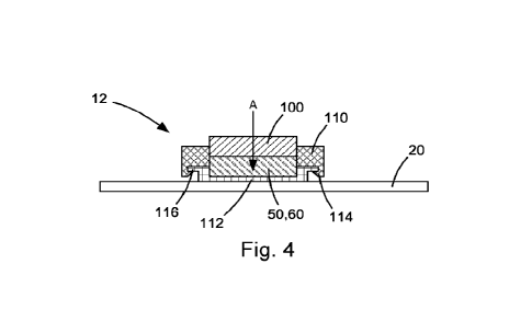
[0045] In one particular configuration illustrated in Fig. 4,
the snap-fit can
be facilitated by structure in the form of a mating component mounted to the
wearable 20 adjacent the electrodes 50, 60 or even configured as a portion
(e.g., base portion) of the electrodes. The structure producing this snap-fit
can
include a component associated with the electrodes 50, 60 and a component
associated with the interface pad 100.In the example of Fig. 4, one
component of the snap-fit structure can be a bezel or housing 112 that
supports the electrodes 50, 60, respectively, on the wearable 20. In this
configuration, the other component of the snap-fit structure can be snap
hooks 114 on the base 110 that are configured to engage a corresponding lip
116 on the housing 112.
[0046] According to the snap-fit structure of Fig. 4, the
connection of the
base 110 to the wearable 20/electrodes 50, 60 can be configured so that the
interface pad 100 is pressed firmly against the electrodes 50, 60. In fact,
the
base 110 and the housing 112 can be configured to form an interference
between the interface pad 100 and the electrodes 50, 60 so that the interface
pad is deformed into engagement with the electrodes. In this manner, the
resilience of the elastomeric material used to construct the interface pad 100
can maintain an effective contact between the pad and the electrodes 50, 60.
[0047] The interface pad 100 has an electrically conductive
construction.
According to one example construction, the interface pad 100 includes an
elastomeric material impregnated or embedded with an electrically conductive
9
CA 03217363 2023- 10- 31
WO 2022/235607
PCT/US2022/027374
material. Various elastomers, such as thermoplastic elastomers and rubber,
can be implemented. Because it is a commonly used material both for skin
and tissue contact in the medical device field, silicone can be an ideal
material
for constructing the interface pad 100. In this example construction, silicone
is
embedded with one or more electrically conductive fillers. While silicone
provides a soft, comfortable and flexible skin contact, the filler provides
the
required electrical conductivity for conducting the electrical stimulation
signals
from the stimulation electrodes 50 to the skin 90, and from the skin to the
recording electrodes 60. The conductive properties of the interface pad 100
can be modified through the selection of the conductive filler material and/or
the density of the conductive filler material in the pad.
[0048] The electrically conductive materials used to form the
filler can vary.
The electrically conductive filler can, for example, include carbon-based
fillers,
such as carbon, carbon fibers, graphite, or carbon nanotubes. The filler can
also include metals, such as copper (Cu), nickel (Ni), silver (Ag), or
aluminum
(Al). Metal alloys, such as Ag/Cu alloys, Ni/AI alloys, AG/AI alloys, or Ag/Ni
alloys can also be used as a conductive filler. Additionally, material
combinations such as nickel coated graphite, silver coated glass, silver
plated
aluminum, silver coated fabric, conductive spray coated silicone, conductive
foam, silver fabric coated silicone sponge, and silver fabric lined silver
plated
silicone can also be used.
[0049] A silicone material construction of the interface pad
100 is both
durable and washable, as is the wearable device 20. The electrodes 50, 60
can be shielded from moisture by the interface pad 100, which covers the
electrodes. The aforementioned mechanical connection of the interface pads
100 to the electrodes/wearable, and the resulting compression of the pads
onto the electrodes 50, 60 can help bolster this shielding. The interface pads
100 being installed on a neurostimulator 12 on a wearable 20 allows for skin
placement without the need for adhesives, which deteriorate over time. The
interface pad 100, being free from adhesives, is also washable and can be
used repeatedly without deteriorating. The neurostimulator 12 can therefore
significantly reduce or eliminate the burden of pad replacement. At the same
time, the interface pads 100 can maintain a high electrical conductivity
contact
CA 03217363 2023- 10- 31
WO 2022/235607
PCT/US2022/027374
with the skin. Additionally, because the silicone pad shields the electrode,
it
also substantially reduces the risk of localized skin burn, in the event a
patient
improperly applies or fails to use the gel pads.
[0050] The interface pad 100 can be manufactured in a variety
of manners,
implementing the different filler materials and/or different elastomeric
materials in various combinations. The interface pads 100 can be
manufactured by molding a sheet of the elastomeric material with embedded
conductive fillers and cutting or stamping the pads from the sheet using, for
example, a cutting die. Other manufacturing methods, such as injection
molding or compression molding, can also be used to manufacture the
interface pads 100. The interface pads 100 can also be fixed to the
neurostimulator, i.e., to the wearable device 20 and/or the electrodes 50, 60
in
a variety of manners in addition to the snap-fit structure described with
reference to Fig. 4. These additional fixations can include, for example,
adhesives, mechanical fasteners, thermal bonding, stitching, or co-building
the wearable and pad by way of an overmolding process.
[0051] An interface between the skin 90 and stimulation
electrodes 50 has
certain technical performance characteristics that can be measured and used
to determine the effectiveness of the neurostimulator 12. The interface pads
100 achieves and enhances these characteristics in a design implementing a
long-lasting conductive elastomeric material construction. Among the
advantageous technical performance characteristics realized through this
construction are:
= Uniform distribution of current.
= Reduced current density.
= Efficient conduction of current from electrode to skin.
= Finite impedance and DC block for stimulation current.
= Enhanced impedance control.
[0052] From the above, it will be appreciated that the
interface pad can be
constructed in various configurations that combine the aforementioned
features, materials, and constructions in different combinations to achieve
these technical performance characteristics.
11
CA 03217363 2023- 10- 31
WO 2022/235607
PCT/US2022/027374
Example Configuration 1
[0053] According to one example configuration, the interface
pad 100 can
be a single layer sheet of silicone impregnated with conductive particles or
having conductive particles embedded therein. With its single layer silicone
construction, the interface pad can provide a uniform pressure distribution
with the skin, and hence a controlled and low impedance determined by the
conductive filler particles. The interface pad 100 can thus provide a
controlled,
finite impedance, which produces an efficient conduction of current from the
electrode to the skin (and vice versa), with a uniform current distribution
and
reduced current density. The impedance can be determined in a variety of
manners, such as through the type of filler material, the amount or density of
filler material, the orientation of filler material particles in the pad or a
combination thereof.
Example Configuration 2
[0054] Referring to Fig. 5, according to another example
configuration, the
interface pad 100 can be a multi-layered pad including at least one low
conductivity layer 120 and at least one high conductivity layer 122. In the
example configuration of Fig. 5, the interface pad 100 includes two low
conductivity layers 120 and two high conductivity layers 122. The conductivity
of the layers can be determined, for example, by the type of filler material
in
each layer, the amount or density of filler material in each layer, the
orientation
of filler material particles in each layer, or a combination thereof.
[0055] As an illustration, for example, the conductivity of
low conductivity
layers 120 can be small, e.g., 1/10, of the conductivity of the high
conductivity
layer 122. In this case, even if the current inflow was not uniform, the high
conductivity of layer 122 spreads the current by allowing it to flow
transversely
due to its high conductivity, which promotes the spread and flow of electrical
current throughout the layer. The evenly distributed current can then flow
uniformly distributed through the remaining layers.
[0056] Fig. 5 illustrates current flow through various layers
120, 122 of the
interface pad 100 with arrows. In Fig. 5, the current flowing through the
upper
low conductivity layer 120 is concentrated toward the center, as indicated by
12
CA 03217363 2023- 10- 31
WO 2022/235607
PCT/US2022/027374
the current arrows being located generally centrally in that layer. The
middle,
high conductivity layer 122 spreads and distributes more evenly the current
from the top layer 120. As a result, the current is transferred from the
middle
layer 122 to the bottom low conductivity layer 120 evenly, and the current
passes through the bottom layer as such. As a result, the multi-layer
configuration of the interface pad 100 produces a uniform current flow so that
the stimulation can be applied, as intended, to the desired area on the
subject's skin 90 via the stimulation electrodes 50. Similarly, the layers of
the
interface pad 100 of Fig. 5 can spread/distribute the current collected from
the
desired location on the skin 90, which is sensed by the recording electrodes.
The interface pad 100 can thus provide a controlled, finite impedance, which
produces an efficient conduction of current from the electrode to the skin
(and
vice versa), with a uniform current distribution and reduced current density.
Example Configuration 3
[0057] According to another example configuration, the
interface pad 100
can be constructed with one or more elastomeric layers with conductive
particles embedded therein. The conductive particles can be oriented with a
bias to achieve this preferential pathway and non-isotropic conductivity. Fig.
6
illustrates three different layers that can be implemented in the interface
pad
100. Each layer is a body of elastomeric material 130 as disclosed herein,
with conductive particles 132, represented bylines, embedded therein.
[0058] A first layer or body 134 has particles 132 arranged
vertically, with
that vertical representation being indicative of the direction or orientation
of
the conductive particles. This vertical direction is transverse to the
thickness
of the layer 134 and thus indicates that the layer is highly conductive, at
least
comparatively speaking. A second layer or body 136 has particles 132
arranged at an angle representing the direction or orientation of the
conductive particles. This direction, being angled and non-vertical relative
to
the thickness of the layer 136, indicates that the layer is less conductive
than
the highly conductive layer 134, comparatively speaking. A third layer or body
138 has particles 132 arranged at an angle representing the direction or
orientation of the conductive particles. The angle of the particles 132 of
layer
138 is greater (with respect to vertical) than the angle of the particles of
layer
13
CA 03217363 2023- 10- 31
WO 2022/235607
PCT/US2022/027374
136. This indicates that the layer is less conductive than both the first
layer
134 and the second layer 136, again comparatively speaking.
[0059] Accordingly, it will be appreciated that the
conductivity of the
interface pad 100 can be tailored through the arrangement of layers with
conductive particles arranged at different orientations. The interface pad 100
can therefore be configured to focus its sensitivity in certain areas.
Additionally, the orientation of conductive particles in this example
configuration can be combined with the variable conductivity layers of
example configuration 2 (see above), for example, so that the current is
distributed evenly through example configuration 2, and then focused
according to example configuration 3, so that the focused current is uniforms
across the focused areas. The interface pad 100 can thus provide a
controlled, finite impedance, which produces an efficient conduction of
current
from the electrode to the skin (and vice versa), with a uniform current
distribution and reduced current density.
Example Configuration 4
[0060] According to another example configuration, the
interface pad 100
can be constructed with multiple elastomeric layers with conductive particles
embedded therein. The layers can, for example, be arranged as described
herein in regard to other example configurations. The multiple layered
structure may provide higher interstitial capacitance, thus block DC current
in
a manner similar to that achieved by hydrogel materials. At the same time, the
interface pad 100 can also provide a controlled, finite impedance, which
produces an efficient conduction of current from the electrode to the skin
(and
vice versa), with a uniform current distribution and reduced current density.
Example Configuration 5
[0061] According to another example configuration, the
interface pad 100
can be constructed with one or more elastomeric layers with conductive
particles embedded therein. Additionally, the one or more layers can also
include an embedded dry electrolyte in order to provide ionization response
similar to those provided by a hydrogel with saline. At the same time, the
interface pad 100 can also provide a controlled, finite impedance, which
14
CA 03217363 2023- 10- 31
WO 2022/235607
PCT/US2022/027374
produces an efficient conduction of current from the electrode to the skin
(and
vice versa), with a uniform current distribution and reduced current density.
Example Embodiment 6
[0062] According to another example configuration, the
interface pad 100
can be constructed with one or more elastomeric layers with conductive
particles embedded therein. The one or more layers can be constructed with a
very low hardness elastomeric substrate material. For example, the substrate
material can be a silicone material with a hardness ranging from 30 to 70
Shore A hardness. Combined with adequate mounting pressure, this soft
substrate material can eliminate localized low-resistivity spots and provide
maximum comfort. The mounting pressure can be provided by the base 110
and housing 112 mounting described above in reference to Fig. 4. This
overcomes the limitation of hydrogels which, after partial drying, can cause
localized current paths. At the same time, the interface pad 100 can also
provide a controlled, finite impedance, which produces an efficient conduction
of current from the electrode to the skin (and vice versa), with a uniform
current distribution and reduced current density.
[0063] Sample configurations were tested for electrical
properties and the
resistance values are listed below. Each sample consisted of a single layer
pad, with the resistance being measured across opposing faces of the pad.
Each sample was used in conjunction with a wearable garment with
embedded electrodes, while ensuring that the surface of the electrode was
generally covered by the interface pads 100. There was no direct contact
between the skin and the electrodes.
Pad Material/Embedded Material Resistance (ohms)
Silver Plated Aluminum 12.7
Silver Coated Fabric 0.7
Conductive Spray Coated Silicone 31k
Conductive Foam 1.8
Silver Fabric Coated Silicone Sponge 1.2
Silver Fabric Lined Silver Plated Silicone 152
[0064] While the resistance values vary among these materials
and
constructions, each of these samples was able to provide and transmit
CA 03217363 2023- 10- 31
WO 2022/235607
PCT/US2022/027374
stimulation current without noticeable discomfort. Furthermore, each sample
was able to elicit a muscular response, validating that the nerve was
successfully recruited and was able to be stimulated.
[0065] From this, it can be appreciated that, the electrical
performance of
the interface pad 100 can be tailored through the careful selection of
material
properties of its components. For example, the number of layers, the
proportion of axial vs. transverse resistivity, the surface properties of each
layer, the relative conductivity of each layer, and the form factor of the
interface pad itself can be adjusted and/or combined in order to arrive at
interface pad configurations with a desired electrical performance
characteristics, such as resistance and capacitance.
[0066] While aspects of this disclosure have been particularly
shown and
described with reference to the figures and the examples described above, it
will be understood by those of ordinary skill in the art that various
additional
aspects may be contemplated. For example, in this description, the electrical
performance of the interface pad is described in terms of conductivity and in
terms of impedance. These properties are, of course, inverse in that as
impedance increases, conductivity decreases, and vice versa. It will therefore
be appreciated that performance of the interface pad described with reference
to one of these properties can also be considered as describing the pad with
reference to the other of the properties. Additionally, a device or method
incorporating any of the features described herein should be understood to
fall
under the scope of this disclosure as determined based upon the claims
below and any equivalents thereof. Other aspects, objects, and advantages
can be obtained from a study of the drawings, the disclosure, and the
appended claims.
16
CA 03217363 2023- 10- 31