Note: Descriptions are shown in the official language in which they were submitted.
WO 2022/236114
PCT/US2022/028159
ASYMMETRIC DELTA MULTI-PULSE TRANSFORMER RECTIFIER UNIT, AND
ASSOCIATED SYSTEMS AND METHODS
CROSS-REFERENCE(S) TO RELATED APPLICATION(S)
This application claims priority to U.S. Provisional Patent Application
No. 63/185520, filed May 7, 2021, which is incorporated by reference herein in
its entirety.
BACKGROUND
Commercial aircraft continue to evolve into More Electric Aircraft (MEA),
featuring increased electrical content in place of hydraulic and pneumatic
systems. Recent
advances in the fields of power electronics and high-density electric motors,
along with
continued pressure to reduce operating costs, ensure that this trend will
continue.
Furthermore, the aircraft propulsion is moving toward hybrid-electric, turbo-
electric, and
even all-electric powertrains. Under some scenarios, the move to electric
propulsion is
expected to increase electrical system power demand by greater than forty
times.
Modern aircraft continue to increase power demand from aircraft low voltage
(typically 28V) and high voltage (typ. 270V, 540V, or greater) DC buses.
Increased
proportion of electrical power demand from AC generators by DC buses requires
increased
AC to DC converter power quality to mitigate undesirable effects like AC bus
voltage
distortion and generator harmonic torque.
Aircraft 28V buses are conventionally sourced by Transformer Rectifier Units
(TRUs) These TRUs convert 3-phase AC voltage provided by aircraft generators
to a
nominal 28VDC. The primary functional blocks of the TRU are the transformer
and the
bridge rectifier. The transformer provides multiphase Power Factor Correction
(PFC),
galvanic isolation, and voltage step-down prior to bridge rectification The
bridge rectifier
rectifies the transformer AC phase outputs, converting output voltage to DC.
Some conventional 28V TRU systems rely on one primary (wye or delta) with two
secondaries, a wye and a delta, to establish 6 AC output phases (allowing 12-
pulse
rectification) that are converted to a DC voltage. Due to low minimum
secondary turns
count (7 turns per delta winding, 4 turns per wye winding) this is effective
at providing
high current output (200-300A). However, this approach requires use of an
interphase
transformer (resulting in increased weight and reduced efficiency) to reduce
output voltage
-1 -
CA 03217978 2023- 11- 3
WO 2022/236114
PCT/US2022/028159
ripple and account for natural voltage imbalance between the delta and wye
secondaries,
and only 12-pulse power quality can be achieved.
Other conventional TRU designs use multiple transformers with complementary
zig-zag secondary windings to provide better than 12-pulse power quality. High
output
current and excellent power quality can be achieved with this approach, but
use of multiple
transformers with complex windings significantly increases manufacturing cost,
increases
weight, and reduces overall power density.
Some conventional methods rely on a delta primary and a hexagonal secondary to
provide 24-pulse power quality with use of simpler discrete output inductors
rather than
complex interphase transformers. This approach provides a high performance and
weight-
competitive solution for lower current (<200A) TRUs, but high minimum
secondary turns
count (66 turns for best harmonic performance, 48 turns bare-minimum) causes
high
leakage inductance and resistive loss in the transformer, resulting in low
efficiency, high
weight, and poor output voltage regulation in high current (>200A)
applications.
In some conventional applications, aircraft high voltage buses (e.g., 270V or
540V)
are sourced by Auto-Transformer Rectifier Units (ATRUs). ATRUs provide passive
multiphase PFC and AC to DC conversion, but without galvanic isolation,
because ATRUs
use autotransformers rather than transformers for multiphase PFC. Since there
is no
galvanically isolated secondary, autotransformers use primary side correction
windings to
generate additional phases needed for multiphase PFC. These autotransformers
are
inherently lighter and more efficient than similarly rated transformers
because
autotransformers have a significant portion of the power electrically
conducted by the
windings and not magnetically coupled thru the core. However, unless generator
neutral is
isolated from airframe, ATRU output return cannot be tied directly to
airframe. Since
generator neutral is typically referenced to airframe, ATRU output voltage is
seen as a split
voltage relative to airframe. This is commonly acceptable for high voltage
point-of-use
loads including motor drives, radar, and de-icing equipment, but this approach
creates
challenges for wide-spread DC distribution due to high common-mode voltage and
inability to reference output voltage independently of input voltage. Since
autotransformers
cannot provide galvanic isolation, many aircraft applications will require a
high voltage
TRU (HVTRU). Due to high power levels, 18 pulse or 24 pulse power quality is
likely to
be required in practical systems. Furthermore the above-described conventional
ATRU
approaches suffer from one or more of the following shortcomings: high common-
mode
-2-
CA 03217978 2023- 11- 3
WO 2022/236114
PCT/US2022/028159
voltage, only supports loads where return is not tied to airframe, inability
to reference
output voltage independently of input voltage.
In summary, the above-described conventional 28V TRU approaches suffer from
one or more of the following shortcomings: low (e.g., 12 pulse) power quality,
required use
of interphase transformers, complex assembly processes requiring multiple
transformers,
high weight, and/or high minimum secondary turns count. On the other hand,
modern
ATRUs are available with low weight, high efficiency, and excellent power
quality (18-24
pulse) without requiring use of interphase transformers, but they cannot
provide galvanic
isolation between 3-phase AC input and DC output. Accordingly, systems for AC
to DC
conversion that are capable of providing better than 12 pulse power quality
without use of
interphase transformers and with galvanic isolation are still needed.
Additionally, high
current 28V applications need low (<40) secondary turns count to minimize
resistive and
reactive voltage drop in the transformer.
SUM1VIARY
This summary is provided to introduce a selection of concepts in a simplified
form
that are further described below in the Detailed Description. This summary is
not intended
to identify key features of the claimed subject matter, nor is it intended to
be used as an aid
in determining the scope of the claimed subject matter.
The inventive technology allows conversion from a 3-phase AC voltage to a DC
voltage with the output voltage being proportional to input voltage and the
output
electrically isolated from the input. For example, the present technology
provides a
nominal 28 Volt DC, 270 Volt DC, or 540 Volt DC output from a commonly used
115 Volt
AC or 230 Volt AC input in modern aerospace power systems. The output voltage
is
proportional to input voltage and transformer primary-secondary turns ratio.
In some embodiments of the inventive technology, the asymmetric delta
secondary
transformer topology may be uniquely suited to provide high performance in
conjunction
with low weight and cost in both HVTRUs and high current 28V TRUs. The
asymmetric
approach offers substantially reduced weight relative to a symmetric 18P
solution, because
the correction windings can be made with fewer turns and carry less current
than they
would in a symmetric delta design.
In some embodiments, the inventive TRU technology allows efficient,
lightweight
18 or 24 pulse operation with high voltage output or nominal 28V output.
Construction of
-3 -
CA 03217978 2023- 11- 3
WO 2022/236114
PCT/US2022/028159
the transformer may consist of a standard 3-phase delta or wye primary coupled
to a
galvanically isolated 3-phase delta secondary with correction windings placed
per the
transformer schematic to provide a 9-phase asymmetric output for the 18-pulse
operation
or a 12-phase asymmetric output for the 24-pulse operation, therefore
providing passive
multiphase power phase correction (PFC) and harmonic cancellation and allowing
18-pulse
or 24-pulse rectification. Output phases of the individual secondary
correction windings
are asymmetric such that individual output phase voltages are controlled
relative to the
opposite secondary delta corner phase, and the secondary output phase voltages
are
unbalanced relative to secondary neutral. In the context of this
specification, secondary
delta windings and secondary correction windings are collectively referred to
as the
secondary windings.
The isolated (e.g., galvanically isolated) 9-phase or 12-phase transformer
output
may be fed into an 18-pulse or 24-pulse bridge rectifier, which converts the
AC to DC. DC
output voltage may be determined by AC input voltage and transformer turns
ratio. For
example, for the 18-pulse TRU, total input current harmonic distortion is
expected to be 5-
7% in most applications, which is a substantial improvement compared to the 11-
14% that
is typical of 12 pulse TRUs. The 24-pulse TRU is expected to provide 3-5%
total input
current harmonic distortion in most applications.
For 28V TRU applications, the inventive technology offers cost reduction
relative
to the 24P delta-hex solution, and it supports significantly higher output
currents than the
delta-hex is practically capable of. The inventive technology offers
substantial
improvements to 28V TRU power quality by providing cancellation of the 11th
and 13th
harmonics, which commonly require specification deviations for 12-pulse TRUs
For HVTRU applications, the asymmetric 18-pulse (18P) or 24-pulse (24P) delta
approach offers substantially improved power quality relative to 12-pulse
(12P) solutions
and substantially reduced weight relative to symmetric 18- or 24-pulse
solutions.
Therefore, the inventive asymmetric 18P and 24P delta transformers offers
excellent power
quality for low cost and minimal weight penalty.
In high voltage DC applications, the inventive TRU technology utilizes 18-
pulse/24-pulse transformer winding topology coupled to a delta or wye primary
to provide
a galvanically isolated 270VDC or 540VDC nominal output with excellent power
quality.
The inventive technology may result in power density greater than 2.4kW/kg and
efficiency
greater than 96%. Despite the addition of galvanic isolation, these numbers
are much closer
-4-
CA 03217978 2023- 11- 3
WO 2022/236114
PCT/US2022/028159
to conventional ATRU technologies (-3kW/kg, >97% eff.) than to conventional
TRU
technologies (<1kW/kg, >90% eff.). Galvanic isolation between the TRU' s AC
input and
DC output allows the TRU' s output return to be tied to airframe, making its
use possible
in applications requiring a unipolar output. Additionally, the inventive HVDC
TRU
technology maintains the inherent ruggedness and reliability for aerospace
applications.
The inventive technology simplifies the system and reduces the risk while
still providing
excellent performance and low weight.
In one embodiment, a Transformer Rectifier Unit (TRU) includes an asymmetric
transformer having: a first coil, a second coil and a third coil. Each coil
includes a primary
winding and a secondary winding, each secondary winding is an asymmetric
secondary
winding, and each coil is configured for being energized at its corresponding
input phase.
The TRU also includes a galvanic isolation electrically isolating primary
windings from
secondary windings, where: a first secondary winding includes a first
secondary delta
winding and a first plurality of secondary correction windings coupled to a
first primary
winding; a second secondary winding includes a second secondary delta winding
and a
second plurality of secondary correction windings coupled to a second primary
winding;
and a third secondary winding includes a third secondary delta winding and a
third plurality
of secondary correction windings coupled to a third primary winding. The TRU
also
includes a bridge rectifier having a plurality of rectifiers coupled to
respective individual
correction windings, where output phases of individual secondary correction
windings are
asymmetric such that individual output phase voltages are controlled relative
to an opposite
secondary delta corner phase, and where the output phase voltages are
unbalanced relative
to secondary neutral.
In one aspect, the transformer is an 18-pulse transformer having a 3-phase
input
power, and an isolated 9-phase output.
In one aspect, each plurality of secondary correction windings includes 2
secondary
correction windings.
In one aspect, tap points of each plurality of correction windings separate
each
corresponding coil of the secondary delta winding into 3 segments.
In one aspect, individual phase voltages are about 20 offset from one phase
to a
next adjacent phase at the bridge rectifier.
In another aspect, the transformer is a 24-pulse transformer having a 3-phase
input
power, and an isolated 12-phase output. Each plurality of secondary correction
windings
-5-
CA 03217978 2023- 11- 3
WO 2022/236114
PCT/US2022/028159
comprises 3 secondary correction windings. Tap points of each plurality of
correction
windings separate each corresponding coil of the secondary delta winding into
4 segments.
Individual phase voltages are about 15 offset from one phase to a next
adjacent phase at
the bridge rectifier.
In one aspect, the bridge rectifier includes: a main rectifier configured for
rectifying
AC voltages of the secondary delta windings; and a secondary rectifier
configured for
rectifying AC voltages of the correction windings.
In one aspect, the main rectifier provides about 66% of DC power, and the
secondary rectifier provides about 34% of DC power.
In one embodiment, a method for designing an asymmetric transformer is
presented. The asymmetric transformer has a first coil, a second coil, a third
coil, and a
galvanic isolation. Each coil includes a primary winding and a secondary
winding. Each
secondary winding is an asymmetric secondary winding having a secondary delta
winding
and a plurality of secondary correction windings. The galvanic isolation is
configured for
electrically isolating primary windings from secondary windings. The method
includes:
selecting turns count for the primary windings of the coils; selecting turns
count for each
of the secondary delta windings of the coils; selecting tap points for
secondary correction
windings along a first secondary delta winding of the first coil, a second
secondary delta
winding of the second coil and a third secondary delta winding of the third
coil. The tap
points divide each of the first secondary delta winding, the second secondary
delta winding
and the third secondary delta winding into segments. The method also includes
constructing
transformer vector diagram using an equilateral triangle with leg lengths
proportional to a
number of turns between secondary corner phases. Each side of the triangle
represents one
of the first, second and third secondary delta windings. The method also
includes drawing
lines representing individual secondary correction windings off of each tap
location along
the first, second and third secondary delta winding. Each line is represented
as a vector of
a first plurality of vectors with a phase equivalent to a phase of the coil
the secondary
correction winding is wound upon and length proportional to secondary
correction
windings turns count. Each vector of the first plurality of vectors runs
parallel to one of
sides of the triangle. The method also includes determining each secondary
correction
winding's turns ratio by the length of a corresponding vector of the first
plurality of vectors;
and determining a number of turns in each second correction winding as a
multiple of the
turns ratio and the number of turns in the complete secondary delta winding.
-6-
CA 03217978 2023- 11- 3
WO 2022/236114
PCT/US2022/028159
In one aspect, the method also includes determining output phases of the
transformer by: drawing a vector of a second plurality of vectors from an end
of each
correction winding vector to an opposite vertex of the equilateral triangle;
and determining
an output phase of each correction winding by a length of a corresponding
vector of a
second plurality of vectors.
In one aspect, an output phase of each correction winding is proportional to a
magnitude of a corresponding output phase relative to a phase represented by
an opposite
vertex of the triangle.
In one aspect, the transformer is an 18-pulse transformer having a 3-phase
input
power, and an isolated 9-phase output. Each plurality of secondary correction
windings
includes 2 secondary correction windings, and tap points of each plurality of
correction
windings separate each corresponding coil of the secondary delta winding into
3 segments.
Individual phase voltages are about 20 offset from one phase to a next
adjacent phase at a
bridge rectifier.
In one aspect, the transformer is a 24-pulse transformer having a 3-phase
input
power, and an isolated 12-phase output.
In one aspect, each plurality of secondary correction windings includes 3
secondary
correction windings, and tap points of each plurality of correction windings
separate each
corresponding coil of the secondary delta winding into 4 segments, and
individual phase
voltages are about 15 offset from one phase to a next adj acent phase at a
bridge rectifier.
DESCRIPTION OF THE DRAWINGS
The foregoing aspects and the attendant advantages of the inventive technology
will
be more readily appreciated as the same become better understood by reference
to the
following detailed description, when taken in conjunction with the
accompanying
drawings, wherein:
Figures 1A and 1B illustrate an 18-pulse asymmetric TRU according to an
embodim ent of inventive technology;
Figures 2A and 2B illustrate a 24-pulse asymmetric TRU according to an
embodiment of inventive technology;
Figure 3 illustrates a delta-wound asymmetric transformer according to an
embodiment of inventive technology;
-7-
CA 03217978 2023- 11- 3
WO 2022/236114
PCT/US2022/028159
Figure 4A illustrates primary delta windings of a multi-pulse asymmetric
transformer according to an embodiment of inventive technology;
Figures 4B and 4C illustrate secondary delta and secondary correction windings
of
an 18-pulse asymmetric transformer according to an embodiment of inventive
technology;
Figure 4D illustrates secondary delta and secondary correction windings of a
24-
pulse asymmetric transformer according to an embodiment of inventive
technology;
Figures 5-8 illustrate secondary delta and secondary correction windings for
an 18-
pulse asymmetric transformer according to an embodiment of inventive
technology;
Figures 9-16 illustrate secondary delta and secondary correction windings for
a 24-
pulse asymmetric transformer according to an embodiment of inventive
technology,
Figure 17 is a flowchart of a method for designing a multi-pulse asymmetric
transformer according to embodiments of inventive technology;
Figure 18 is a graph of simulated 3-phase input current waveforms for an 18-
pulse
asymmetric TRU utilizing an ideal transformer of the topology depicted in Fig.
4B;
Figure 19 is a graph of simulated rectifier bridge currents for an 18-pulse
asymmetric TRU utilizing an ideal transformer of the topology depicted in Fig.
4B;
Figure 20 is a graph of simulated phase A input voltage and current for an 18-
pulse
asymmetric TRU utilizing an ideal transformer of the topology depicted in Fig.
4B; and
Figure 21 is a graph of actual 3-phase input current waveforms according to an
embodiment of inventive technology.
DETAILED DESCRIPTION
While illustrative embodiments have been illustrated and described, it will be
appreciated that various changes can be made therein without departing from
the spirit and
scope of the invention.
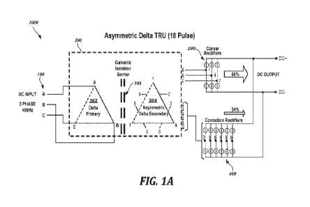
Figure 1A illustrates an 18-pulse asymmetric delta TRU 1000 according to an
embodiment of inventive technology. At the input side, 3-phase AC power 100
(typically
115 Volt or 230 Volt) is supplied to a transformer 300. The three input phases
of the
primary delta winding A, B, C are fed into the primary delta 302 and are
transformed into
the output phases 1, 4, 7 of the secondary delta 304. In some embodiments, the
3-phase
delta primary 302 is coupled through a galvanic isolation 306 to a 3-phase
asymmetric delta
secondary 304. Galvanic isolation 306 limits fault propagation and allows TRU
DC output
-8-
CA 03217978 2023- 11- 3
WO 2022/236114
PCT/US2022/028159
returns to be tied directly to airframe regardless of generator's neutral
voltage or
impedance.
Power coming off the secondary delta winding taps 1, 4, 7 is fed into the
corner
rectifiers (also referred to as the main rectifiers) 200 that rectifies the
majority of power
coming from the secondary windings (e.g., about 66% in some cases) into a DC
voltage
(e.g., 540V). The secondary delta windings connected to winding taps I, 4, 7
provide 6
pulses at the output of the main rectifier circuit 200. The remaining power
may be fed off
the secondary correction windings connected to winding taps 2, 3, 5, 6, 8, 9
to the correction
rectifiers 400 (also referred to as the secondary rectifiers) that rectify the
remaining power
(e.g., about 34% in some cases), allowing power factor correction and harmonic
cancellation of the 3-phase input currents. As a result, a significant size,
weight, and
dissipation reduction may be achieved in the transformer 300. The 66% vs. 34%
distribution of power is an illustrative embodiment only, in other embodiments
different
fractions of power may be handled by the main rectifier 200 and the secondary
rectifier
400. Secondary delta windings and secondary correction windings are
collectively referred
to as the secondary windings in this specification.
The rectifier circuits 200 and 400 include arrangements of diodes that rectify
the
input AC voltage into DC voltage. With the inventive technology transformer,
the
asymmetric delta TRU 1000 outputs high-quality DC (e.g., 540 Volt DC) while
maintaining an 18-pulse input current waveform with high power factor and low
harmonic
content.
Figure 1B also illustrates a TRU according to an embodiment of inventive
technology. The 3-phase input A, B, C is fed through an input filter 150 into
the transformer
300. In the illustrated embodiment, the 9 output phases (3 output phases from
the secondary
delta winding taps 1, 4, 7; and 6 output phases from the secondary correction
winding taps
2, 3, 5, 6, 8, 9, collectively "output phases 310") are coupled to rectifier
circuits 200, 400
that rectify the incoming 9 phases into 18 pulses. Output phases of the
individual secondary
correction windings are asymmetric such that individual output phase voltages
are
controlled relative to the opposite secondary delta corner phase, and
secondary output
phase voltages are unbalanced relative to secondary neutral. The resulting DC
voltage may
be fed through an output electromagnetic interference (EMI) filter 410 before
being
delivered to the load(s). The illustrated TRU may convert a 230 Volt AC input
to a 540
-9-
CA 03217978 2023- 11- 3
WO 2022/236114
PCT/US2022/028159
Volt DC output. In other embodiments, different AC input and DC output
voltages may
be produced.
Figures 2A and 2B illustrate a 24-pulse asymmetric delta TRU 1000 according to
an embodiment of inventive technology. Again, at the input side, 3-phase AC
power 100
(typically 115 Volt or 230 Volt) is supplied to the transformer 300. The three
input phases
of the primary delta winding A, B, C are fed into the primary delta 302 and
are transformed
into the output phases 1, 5, 9 of the secondary delta 304. Power coming off
the secondary
delta winding taps 1, 5, 9 is fed into the corner rectifiers 200 that rectify
the majority of
power (e.g., about 66%) being processed by the TRU into a DC voltage (e.g.,
540V).
Therefore, the secondary delta winding taps 1, 5, 9 provide 6 pulses at the
output of the
main rectifier circuit 200. The secondary correction winding taps 2, 3, 4, 6,
7, 8, 10, 11,
12 provide additional 18 pulses to the secondary rectifiers 400 that rectify
the remaining
DC power (e.g., about 34%), allowing power factor correction and harmonic
cancellation
of the 3-phase input currents.
The 3-phase delta primary 302 is coupled through a galvanic isolation 306 to a
3-
phase asymmetric delta secondary 304. As explained above, galvanic isolation
306 limits
fault propagation and allows TRU DC output returns to be tied directly to
airframe
regardless of generator's neutral voltage or impedance.
Figure 2B also illustrates a TRU 1000 according to an embodiment of inventive
technology. Again, the 3-phase input A, B, C is fed through an input filter
150 into the
transformer 300. In the illustrated embodiment, the 12 output phases (3 output
phases from
the secondary delta winding taps 1, 5, 9; and 9 output phases from the
secondary correction
winding taps 2, 3, 4, 6, 7, 8, 10, 11, 12) are coupled to a common rectifier
circuit that
rectifies the 12 phases into 24 pulses. The illustrated TRU may convert a 230
Volt AC
input to a 540 Volt DC output. In other embodiments, different AC input and DC
output
voltages may be used.
Figures 1A-2B illustrate delta primary windings. However, in different
embodiments wye primary windings may be used as the primary windings.
Furthermore,
the discussion herein focuses on the embodiments having 18-pulse and 24-pulse
asymmetric transformers. However, the inventive technology may be applicable
to other
multi-pulse asymmetric transformers where the number of pulses is a multiple
of 3, albeit
with some tradeoffs. For example, an increasing number of pulses that
necessitates an
-10-
CA 03217978 2023- 11- 3
WO 2022/236114
PCT/US2022/028159
increasing number of secondary correction windings generally increases the
size and
weight of the TRU.
Figure 3 illustrates a delta-wound transformer 1000 according to an embodiment
of
inventive technology. The inputs for the primary delta phases are marked as A,
B, C at the
front end of the TRU 1000. In some embodiments, the primary delta windings of
the 3-
phase input and the secondary delta windings are wound as 3 coils 110, 120 and
130. In
the illustrated embodiment, coils 110, 120 and 130 share same ferromagnetic
core 140.
The outputs of the secondary windings (e.g., 3 output phases from the
secondary
delta winding taps 1, 4, 7; and 6 output phases from the secondary correction
winding taps
2, 3, 5, 6, 8, 9) are coupled to rectifier circuits 200, 400 to rectify the
incoming 9 phases
into 18 pulses. A person of ordinary skill would understand that analogous
secondary
windings 1-12 of the 24-pulse TRU may be connected to analogous rectifier
circuits 200,
400 shown in Figures 2A and 2B. The DC outputs DC+ and DC- are marked at the
front
end of the TRU 1000.
Figure 4A illustrates primary delta windings 302 of a multi-pulse asymmetric
transformer according to an embodiment of inventive technology. The primary
delta
windings 302 include phases A, B and C. The illustrated primary delta windings
302
include 50 turns each, but in other embodiments different number of turns are
also possible.
Figures 4B and 4C illustrate secondary 304 with delta windings and secondary
correction windings of an 18-pulse asymmetric transformer according to
different
embodiments of inventive technology. The illustrated secondary windings (delta
and
correction) include 9 output taps (T1-T9) for the 9 output phases that include
3 main phases
and 6 correction phases (also referred to as auxiliary phases) of the
transformer. The
topology orientation is exemplary, and different topology may apply in
different
embodiments. The secondary delta windings and secondary correction windings
are
marked with A, B and C to signify their phase correspondence with respect to
the piimary
delta phases A, B and C.
The number of turns for each winding of the illustrated embodiment is labeled
adjacent to the winding. In Figure 4B, the serial windings along the Ti-coil
(B-phase),
corresponding to the secondary delta winding, have 13, 26 and 13 turns in
series. Each of
the secondary correction windings that are connected to taps T3 and T5 have 7
turns.
Similarly, the serial windings along the T4-coil (A-phase) of the secondary
delta winding
also have 13, 26 and 13 turns in series. The corresponding secondary
correction windings
-11-
CA 03217978 2023- 11- 3
WO 2022/236114
PCT/US2022/028159
providing taps T6 and T8 each have 7 turns. The C-phase secondary windings
have
analogous number and distribution of turns.
In Figure 4C, the serial windings along the Ti-coil (A-phase), corresponding
to the
secondary delta winding, have 2, 4 and 2 turns in series. The illustrated
embodiment,
having a relatively small number of turns in the secondary delta winding, may
be useful
for a relatively low DC output of 28V. Each of the secondary correction
windings that are
connected to, e.g., taps T6 and T8 of the B-phase, has 1 turn. The B-phase and
C-phase
secondary windings (delta and correction) have analogous number and
distribution of turns.
Figure 4D illustrates secondary delta windings and secondary correction
windings
of a 24-pulse asymmetric transformer according to an embodiment of inventive
technology.
The illustrated secondary windings (delta and correction) include 12 output
taps (11-112)
for the 12 output phases that include 3 main phases and 9 correction phases
(also referred
to as auxiliary phases) of the transformer. The topology orientation is
exemplary, and
different topology may apply in different embodiments. The secondary delta
windings and
secondary correction windings are marked with A, B and C to signify their
phase
correspondence with respect to the primary delta phases A, B and C.
For example, the serial windings along the T5-coil (C-phase), corresponding to
the
secondary delta winding, have 9, 12, 21 and 9 turns in series. The secondary
correction
windings that are connected to taps T3, T2 and T12 have 8 turns, 6 turns and 6
turns,
respectively. Similarly, the serial windings along the Ti-coil (A-phase) of
the secondary
delta winding also have 9, 12, 21 and 9 turns in series The corresponding
secondary
correction windings that are connected to taps T8, T10 and T11 have 6 turns, 6
turns and 8
turns, respectively. The B-phase secondary delta and secondary correction
windings have
analogous number and distribution of turns.
In some embodiments, the inventive transformer may be characterized by
following
parameters.
= Input voltage: 115 Vac, 3-phase, 360-800Hz, MIL-STD-704F
= Output voltage: nominal 270Vdc (unregulated)
= Output power: 45 KW
= Efficiency: >96% at >50% load, normal AC input range
= Power Factor: >.95 at >25% load
= Voltage Ripple: <6 Vpp
= Total harmonic distortion (THDi): 18 pulse <7%
-12-
CA 03217978 2023- 11- 3
WO 2022/236114
PCT/US2022/028159
= High current overload capability 150% for 1 minute 200% for 5 seconds
= Reliability: >200k hrs MTBF (assuming external forced airflow provided)
Figures 5-8 illustrate secondary delta and correction windings for an 18-pulse
asymmetric transformer according to an embodiment of inventive technology. For
example, Figure 7 illustrates delta-wound transformer topology diagram for the
18-pulse
transformer of Figures 1A and 1B based on the primary delta windings shown in
Figure
4A and the secondary delta and secondary correction windings shown in Figure
4B. Each
side of the secondary delta has 3 serial windings. For example, looking at the
phase C, the
secondary delta windings include serial windings Ni, N2 and N3 that are
interposed
between taps T4 and T7. Analogous windings are interposed between T4 and Ti
for the
phase A, and between Ti and T7 for the phase B, but are unlabeled on the
diagram to
simplify the drawings and to reduce clutter.
The secondary correction windings for the phase C are labeled N4 and N5.
Secondary delta windings A and B and their corresponding secondary correction
windings
are also not labeled with `Nx' in order to reduce clutter in the drawings.
However, a reader
will recognize that, for example, the secondary correction windings N4 an N5
are drawn to
be parallel to the secondary delta winding C (whose phase these secondary
correction
windings 'correct'). Analogously, the secondary correction windings that
correspond to
each of the secondary delta windings A and B are also drawn to be parallel to
their
respective A and B secondary delta windings. This convention is followed
throughout
Figures 5-12.
A sample method for determining the phase-to-phase voltage in an asymmetric
transformer is described as follows with reference to Figures 5-8. The sample
method
includes drawing a vector from the end of each secondary correction winding
(e.g., taps
T5, T6) to the opposite vertex of the equilateral triangle (e.g., vertex where
phase windings
A and B intersect, i.e., vertex Ti). These vectors represent the transformer
output phases.
Each vector's length is proportional to the corresponding output phase's
magnitude relative
to the phase represented by the opposite vertex of the triangle (not relative
to neutral as in
the symmetric transformer) ¨this phase-to-phase voltage is presented to the
bridge rectifier
as a conduction pair as shown in Table 2. In some embodiments, triplen
harmonic
mitigation is guaranteed by the secondary delta winding formed by N1-N3 turns
ratios,
which provide a suitable winding configuration for triplen harmonics
mitigation.
-13-
CA 03217978 2023- 11- 3
WO 2022/236114
PCT/US2022/028159
As noted above, the desired phase shifting of transformer output phases is
obtained
from the secondary correction windings tapped at the select locations between
the serial
windings traversing the input phases and providing outputs at T2, T3, T5, T6,
T8, and T9.
The coil that the secondary correction winding is wound upon and winding
polarity of the
secondary correction winding determine the direction of the phase shift the
secondary
correction winding provides to its output phase. Each correction winding's
turns ratio along
with its tapping point between the serial windings determines the final phase
angle and
magnitude of its output phase. These output phase magnitudes and phases are
illustrated
diagrammatically by the lines.
For the 18-pulse behavior, nominal 20 spacing is desired between adjacent
phases.
As explained above, practical output phase magnitude will depend on
transformer
construction, parasitics (e.g., leakage inductance), and use case (e.g.,
source and load
impedance).
For the embodiment illustrated in Figure 5, the secondary turn ratios are
shown in
Table 1 below. The turns ratio for a given secondary winding may be defined as
the ratio
of the winding's turns to the total turns between each secondary corner phase.
This is not
to be confused with the transformer's primary to secondary turns ratio, which
in its simplest
form is the ratio of the primary delta turns count to the secondary delta
turns count. In some
embodiments, the illustrated turns ratios may be approximate, because the
optimum turns
ratios may vary with transformer construction, different parasitics, and use
case. As a result,
a practically-implemented turns count may vary with the selected transformer
core.
Table 1: Turn Ratios in Figure 5
Winding Ni N2 N3 N4
N5
Turns Ratio 0.26 0.35 0.39 0.14
0.14
For the embodiments illustrated in Figures 6-8, the turn ratios are shown
below in
Tables 2-4, respectively.
Table 2: Turn Ratios in Figure 6
Winding Ni N2 N3 N4
NS
Turns Ratio 0.39 0.21 0.39 0.14
0.14
-14-
CA 03217978 2023- 11- 3
WO 2022/236114
PCT/US2022/028159
Table 3: Turn Ratios in Figure 7
Winding Ni N2 N3 N4
N5
Turns Ratio 0.26 0.48 0.26 0.14
0.14
Table 4: Turn Ratios in Figure 8
Winding Ni N2 N3 N4
N5
Turns Ratio 0.39 0.35 0.26 0.14
0.14
Other turn ratios are possible in different embodiments. The examples shown in
Tables 1-4 should be understood as non-limiting examples.
Figures 9-16 illustrate secondary delta and secondary correction windings for
a 24-
pulse asymmetric transformer according to an embodiment of inventive
technology. A
sample 24-pulse asymmetric transformer is shown in Figures 2A and 2B above.
Sample
primary delta windings are shown in Figure 4A, and sample secondary delta and
secondary
correction windings are shown in Figure 4D.
Figure 9 illustrates delta-wound transformer topology diagram for the 24-pulse
transformer. Each side of the secondary delta has 4 serial windings. For
example, looking
at the phase C, the secondary delta windings include serial windings Ni, N2,
N3 and N4.
Analogous serial windings are shown for the phases A and B, but are unlabeled
on the
diagram to reduce clutter. The desired phase shifting of transformer output
phases is
obtained from the secondary correction windings tapped at the select locations
between the
serial windings traversing the input phases, analogous to the method explained
in
conjunction with the 18-pulse transformer above. The coil that the secondary
correction
winding is wound upon and winding polarity of the secondary correction winding
determine the direction of the phase shift the secondary correction winding
provides to its
output phase. Each secondary winding's turns ratio along with its tapping
point between
the serial windings determines the final phase angle and magnitude of its
output phase.
These output phase magnitudes and phases are illustrated diagrammatically by
the lines in
Figures 9-16. For the 24-pulse behavior, nominal 15 spacing is desired
between adjacent
phases.
For the embodiments illustrated in Figures 9-16, the secondary turns ratios
are
shown below in Tables 5-12, respectively.
-15-
CA 03217978 2023- 11- 3
WO 2022/236114
PCT/US2022/028159
Table 5: Turn Ratios in Figure 9
Winding Ni N2 N3 N4 N5 N6
N7
Turns Ratio 0.17 0.24 0.42 0.17 0.13 0.13
0.18
Table 6: Turn Ratios in Figure 10
Winding Ni N2 N3 N4 N5 N6
N7
Turns Ratio 0.17 0.42 0.11 0.30 0.18 0.13
0.13
Table 7: Turn Ratios in Figure 11
Winding Ni N2 N3 N4 N5 N6
N7
Turns Ratio 0.30 0.11 0.29 0.30 0.13 0.18
0.13
Table 8: Turn Ratios in Figure 12
Winding Ni N2 N3 N4 N5 N6
N7
Turns Ratio 0.17 0.24 0.29 0.30 0.13 0.18
0.13
Table 9: Turn Ratios in Figure 13
Winding Ni N2 N3 N4 NS N6
N7
Turns Ratio 0.30 0.29 0.24 0.17 0.13 0.18
0.13
Table 10: Turn Ratios in Figure 14
Winding Ni N2 N3 N4 N5 N6
N7
Turns Ratio 0.30 0.29 0.11 0.30 0.13 0.18
0.13
Table 11: Turn Ratios in Figure 15
Winding Ni N2 N3 N4 N5 N6
N7
Turns Ratio 0.30 0.11 0.42 0.17 0.13 0.13
0.18
Table 12: Turn Ratios in Figure 16
Winding Ni N2 N3 N4 N5 N6
N7
Turns Ratio 0.17 0.42 0.24 0.17 0.18 0.13
0.13
Figure 17 is a flowchart of a method for designing a multi-pulse asymmetric
transformer according to embodiments of inventive technology. In particular,
illustrated
method outlines a design process of selecting turns ratios for proper output
phase
magnitudes and spacing for asymmetric 24-pulse operation. In different
embodiments,
illustrated method may include additional steps or may include other steps not
shown in
the flowchart.
-16-
CA 03217978 2023- 11- 3
WO 2022/236114
PCT/US2022/028159
The method may start in block 510. In blocks 515 and 520, primary and
secondary
phase-to-phase turns counts are selected. These turns count selection is made
so to maintain
acceptable flux density for selected core, operating frequency, operating
voltage, and input
to output voltage scaling.
In block 525, transformer vector diagram is constructed for the secondary
windings
using an equilateral triangle with leg lengths proportional to the number of
turns between
corner phases. Each side of the triangle represents a complete delta winding
and consists
of 3 segments (for an 18-pulse asymmetric transformer) or 4 segments (for a 24-
pulse
asymmetric transformer) between each pair of triangle vertices (see, e.g.,
Figures 5 and 9).
Each segment represents a serial winding and has a length proportional to the
turns count
of the applicable serial winding. The points between the vertices of each leg
where
segments meet represent locations of the secondary correction winding tap.
In block 530, lines are drawn representing secondary correction windings off
of
each tap location between triangle vertices. Each line is a vector with phase
equivalent to
the phase of the coil the secondary correction winding is wound upon and
length
proportional to secondary correction windings turn count. Each vector runs
parallel to one
of the sides of the triangle. Each winding's turns ratio is equivalent to the
turns count of
the secondary correction winding divided by the turns count of the full delta
winding. This
is illustrated on the transformer vector diagram as the length of the
correction winding
vector to the length of a full leg of the equilateral triangle.
In block 535, a vector is drawn from the end of each correction winding vector
to
the opposite vertex of the equilateral triangle. These vectors represent the
transformer
output phases. Each vector's length is proportional to the corresponding
output phase's
magnitude relative to the phase represented by the opposite vertex of the
triangle. Vectors
can be drawn from each output tap to neutral which accurately indicate output
phase
voltage relative to neutral, but due to the nature of the asymmetric design of
these phases
to neutral voltages will be uneven. Controlling phase-to-phase voltages rather
than phase-
to-neutral is a difference between asymmetric and symmetric design approaches.
In block 540, delta segment lengths are optimized while maintaining constant
total
delta length to adjust tap locations. In some embodiments, correction winding
vector
lengths are adjusted until output phase vector lengths are approximately equal
to the lengths
of each side of the equilateral triangle, and all vectors originating from
each triangle vertex
maintain approximately 20 phase spacing for the 18-pulse transformer and 15
phase
-17-
CA 03217978 2023- 11- 3
WO 2022/236114
PCT/US2022/028159
spacing for the 24-pulse transformer. Examples of complete transformer vector
drawings
created using this method can be seen in Figures 5-12.
In block 545, serial and correction windings turn counts are set based on the
final
lengths of each serial winding line segment and correction winding vector in
the
transformer vector drawing. The method may end in block 545.
Figures 18-20 are graphs of simulated current waveforms for an 18-pulse
asymmetric TRU utilizing an ideal transformer of the topology depicted in
Figures 4A and
4B The simulated asymmetric TRU is called "ideal" because non-idealities such
as leakage
inductance and winding resistance are neglected. A person of ordinary skill
would
understand that analogous graphs can be generated for a 24-pulse asymmetric
TRU. Figure
21 is a graph of actual 3-phase input current waveforms according to an
embodiment of
inventive technology. In each of these graphs, the horizontal axis shows the
elapsed time.
The vertical axis shows electrical current in Amperes.
In particular, Figure 18 is a graph of simulated 3-phase input current
waveforms for
an 18-pulse asymmetric TRU utilizing an ideal transformer of the topology
depicted in
Figures 4A and 4B. Ideal transformer without leakage inductance or winding
resistance
exhibits with a sinusoidal voltage input a stepped current waveform
approximating a sine
wave with 18 "steps" or "pulses". This is the result of bridge rectifier
conduction pairs
switching every 20 . Addition of leakage inductance and winding resistance
serves to
smooth the waveform so that end result is nearly sinusoidal (as shown below in
Figure 21).
Figure 19 is a graph of simulated rectifier bridge currents for an 18-pulse
asymmetric ATRU during one full electrical cycle. The 20 spacing of bridge
rectifier
conduction pairs can be seen as each conductive pair conducts for about 139
microseconds,
or approximately 20 electrical degrees of the given 400 Hz cycle, which has a
period of 2.5
ms. Additionally, it can be seen in Figure 18 that each secondary delta
winding connection
to the bridge rectifier conducts current for 4 consecutive pulses, whereas
each secondary
correction winding only conducts current for 1 pulse in a given half-cycle.
This is indicative
of the majority of power being processed by the TRU coming from the secondary
delta
windings, and minority of power being coming from the secondary correction
windings.
Figure 20 is a graph of simulated phase A input voltage and current for an 18-
pulse
asymmetric TRU utilizing an ideal transformer of the topology depicted in
Figures 4A and
4B.
-18-
CA 03217978 2023- 11- 3
WO 2022/236114
PCT/US2022/028159
Figure 21 is a graph of simulated 3-phase input current waveforms with
expected
TRU non-idealities including winding resistance and leakage inductance
included. In the
illustrated embodiment, the actual current waveforms are smoother (indicating
lower
harmonic distortion) than the ideal input current waveforms shown in Figure
18. This is
because the presence of small amounts leakage inductance can serve to smooth
the input
current waveform. In general, leakage inductance should generally be kept as
small as
possible, though. As can be seen in Figures 19 and 20, the secondary
correction windings
carry pulse currents of high magnitude and short duration. If leakage
inductance is allowed
to be too large, these pulse currents cannot reach their full magnitude, and
the 18-pulse
operation may be degraded such that the effective pulse count is reduced and
the
performance of the 18-pulse ATRU starts to approximate a 12-pulse solution.
Based on the above analysis and simulation, it can be observed that the 18-
pulse
and 24-pulse asymmetric delta TRUs provide distinct advantages for both HVTRU
and
28V TRU applications. The inventive technology offers significant improvement
to power
quality relative to legacy 12-pulse delta-wye solutions with comparable weight
and
efficiency, and it offers slightly lower size and weight and significantly
lower cost than a
24-pulse delta-hex solution since it requires 3 less windings per coil and
does not require
discrete output inductors for proper phase spacing. It is estimated that labor
ratios of a
delta- delta-wye solution, 18P asymmetric delta, and 24P delta hex are
approximately 1 :
1.45: 1.76.
Many embodiments of the technology described above may take the form of
computer- or controller-executable instructions, including routines executed
by a
programmable computer or controller. Those skilled in the relevant art will
appreciate that
the technology can be practiced on computer/controller systems other than
those shown
and described above. The technology can be embodied in a special-purpose
computer,
controller or data processor that is specifically programmed, configured or
constructed to
perform one or more of the computer-executable instructions described above.
Accordingly, the terms "computer" and "controller" as generally used herein
refer to any
data processor and can include Internet appliances and hand-held devices
(including palm-
top computers, wearable computers, cellular or mobile phones, multi-processor
systems,
processor-based or programmable consumer electronics, network computers, mini
computers and the like).
-19-
CA 03217978 2023- 11- 3
WO 2022/236114
PCT/US2022/028159
From the foregoing, it will be appreciated that specific embodiments of the
technology have been described herein for purposes of illustration, but that
various
modifications may be made without deviating from the disclosure. Moreover,
while
various advantages and features associated with certain embodiments have been
described
above in the context of those embodiments, other embodiments may also exhibit
such
advantages and/or features, and not all embodiments need necessarily exhibit
such
advantages and/or features to fall within the scope of the technology. Where
methods are
described, the methods may include more, fewer, or other steps. Additionally,
steps may
be performed in any suitable order. Accordingly, the disclosure can encompass
other
embodiments not expressly shown or described herein. In the context of this
disclosure, the
term "about" means +/- 5% of the stated value.
For the purposes of the present disclosure, lists of two or more elements of
the form,
for example, "at least one of A, B, and C," is intended to mean (A), (B), (C),
(A and B), (A
and C), (B and C), or (A, B, and C), and further includes all similar
permutations when any
other quantity of elements is listed.
-20-
CA 03217978 2023- 11- 3