Note: Descriptions are shown in the official language in which they were submitted.
WO 2022/234427
PCT/IB2022/054030
1
MACHINE FOR THE WELDING OF PLASTIC PROFILED
ELEMENTS
Technical Field
The present invention relates to a machine for the welding of plastic profiled
elements.
Background Art
It is well known that there is a particular need in many sectors of industrial
activity to renew the manufactured articles and to search for new ones in
order
to distinguish them more from those of competitors.
This need is felt, in particular, in the industry involved in the manufacture
of
frames such as doors and windows made of plastic material, particularly PVC.
Such windows and doors consist of a series of plastic profiled elements,
usually
formed by extrusion or similar techniques, that are welded together by means
of
heating plates.
The heating plates obtain the melting of respective areas to be welded of the
profiled elements in order to make a frame structure, inside which a pane of
glass or a central panel can be placed.
Known manufacturing processes for the welding of PVC profiled elements
require that the areas to be welded be properly cut at 45 to allow for
perfect
overlapping of the internal array of the profiled element and consequently
effective welding capable of holding the profiled elements firmly joined
together.
Compared with the windows and doors made of materials such as wood and
aluminum, those made of plastic, although simpler to manufacture and better
performing, are commonly thought to be aesthetically of inferior quality.
Within the plastic window and door industry, therefore, there is a
particularly
strong need to improve the aesthetic appearance of the profiled elements in
order to obtain original products with novel shapes that have innovative
features
aimed at elevating the aesthetic perception of the product and being more
attractive to customers.
In this regard, PVC windows and doors are sometimes made with colors and
CA 03218063 2023- 11- 6
WO 2022/234427
PCT/IB2022/054030
2
finishes that simulate the effect of wood.
The effect of wood can be achieved by means of a flexible plastic or wood
veneer sheet, which is about 0.1 mm thick, is colored to reproduce the effect
of
wood, and is applied to the main faces of the PVC profiled elements, i.e., the
surfaces intended to remain visible after the installation of the window/door.
Alternatively, it is possible to achieve the effect of wood by means of so-
called
"canopies", made of natural wood or wood-effect painted aluminum.
Canopies are half-shells that are applied, by gluing, screwing or
interlocking, to
the profiled elements so as to cover the main faces and partly embrace the
side
surfaces thereof.
However, the aesthetic effect achieved by these manufacturing methods is
different from that of natural wood.
This is due to the differences in construction techniques between natural wood
and plastic windows and doors and in the inherent characteristics of the two
materials.
In particular, natural wood windows and doors are usually made by joining the
longitudinal frame members thereof, wherein a butt portion of one frame
member is interlocked to a rib portion of an adjacent frame member, thus
creating a square joint, rather than a 45-degree joint.
It should be specified that the butt portions consist of end portions at the
end of
a frame member, while the rib portions consist of side portions of a frame
member.
The PVC profiled elements, on the other hand, are assembled by melting butt
portions, thus creating a visibly different quarter-sawn joint than the square
joint
of natural wood windows and doors.
The PVC profiled elements, even when covered by plastic sheets or canopies,
thus inevitably reveal the fact that they are not made of natural wood.
To remedy at least part of these drawbacks, the profiled elements can be
suitably shaped in at least one of the relevant visible faces so as to achieve
a
square joint once the profiled elements are joined together.
Specifically, each profiled element comprises at least one main square-shaped
CA 03218063 2023- 11- 6
WO 2022/234427
PCT/IB2022/054030
3
face, that is, cut at 900.
Specifically, the main face of a first profiled element is projecting from the
relevant area to be welded and the main face of a second profiled element is
recessed with respect to the relevant area to be welded.
The areas to be welded are then melted and the profiled elements coupled
together, so that when the window/door is assembled, the resulting welding
area
has an oblique quarter-sawn joint, while at least one of the main faces has a
square joint, thus giving an aesthetic effect similar to that of natural wood
windows and doors.
The machines of known type for the welding of plastic profiled elements
comprise:
- retaining means adapted to retain the profiled elements with the areas to
be
welded facing each other;
- removal means adapted to remove part of the plastic material from the
areas to be welded;
- heating means adapted to heat the areas to be welded until the plastic
material is at least partly melted; and
- displacement means of the retaining means adapted to displace the
profiled
elements between a mutual away position and a mutual approaching
position, wherein the heated areas to be welded are joined together.
Specifically, the removal means comprise at least one milling tool movable
along the peripheral edge of the areas to be welded to make a groove, through
which the length of the faces of the profiled elements is reduced so that, as
a
result of the welding of the same, the welding bead extends inward into the
profiled elements and, therefore, is not visible from the outside.
In fact, during the joining of the profiled elements, a portion of the molten
plastic material is compressed and may project with respect to the faces of
the
profiled elements themselves.
The machine also comprises suction means associated with the removal means
and adapted to remove the residues of plastic material generated during the
removal.
CA 03218063 2023- 11- 6
WO 2022/234427
PCT/IB2022/054030
4
The suction means comprise a suction port with a substantially circular cross-
section, arranged around the milling tool, in order to carry out effective
removal
of the removed plastic chips.
The machines of known types are susceptible to further refinement.
In fact, during machining operations, the removal means and the suction means
need to be placed in contact with the areas to be welded and to be moved
extremely precisely along the edge of the same, so that the milling tool can
make the groove while the suction port follows the movement of the tool.
However, the projecting part of the main face of the first profiled element
may
hinder the movement and positioning of some machine components, especially
including the removal means and the suction means.
In addition, such a conformation of the first profiled element means that the
profiled elements must be kept at a greater distance from each other, thus
making machining operations even more complex.
Description of the Invention
The main aim of the present invention is to devise a machine for the welding
of
plastic profiled elements which allows even profiled elements provided with a
main face projecting from the area to be welded to be machined effectively.
Another object of the present invention is to devise a machine for the welding
of
plastic profiled elements which allows effective suction of plastic material
residues and at the same time precise movement of the milling tool to the
peripheral edge of the area to be welded.
Another object of the present invention is to devise a machine for the welding
of
plastic profiled elements which can overcome the aforementioned drawbacks of
the prior art within the framework of a simple, rational, easy and effective
to use
as well as affordable solution.
The aforementioned objects are achieved by this machine for the welding of
plastic profiled elements having the characteristics of claim 1.
Brief Description of the Drawings
Other characteristics and advantages of the present invention will become more
apparent from the description of a preferred, but not exclusive, embodiment of
a
CA 03218063 2023- 11- 6
WO 2022/234427
PCT/IB2022/054030
machine for the welding of plastic profiled elements, illustrated by way of an
indicative, yet non-limiting example, in the attached tables of drawings
wherein:
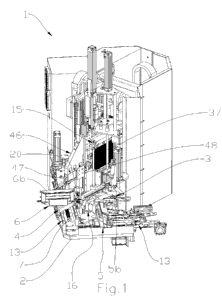
Figure 1 is an axonometric view of the machine according to the invention;
Figure 2 is a schematic representation of the plastic profiled elements which
can
5 be machined by this machine, before and after welding;
Figure 3 is a detailed axonometric view of the retaining means and of the
displacement means according to the invention;
Figure 4 is a front detailed view of the removal means and of the suction
means
according to the invention;
Figure 5 is a side detailed view of the removal means and of the suction means
according to the invention;
Figure 6 is a top detailed view of the removal means and of the suction means
according to the invention;
Figures 7 and 8 are axonometric views of the removal means, of the suction
means and of the relevant positioning system according to the invention;
Figures 9 and 10 are axonometric views of the heating means and of the
relevant movement system according to the invention;
Figures 11 and 12 are axonometric views of the containment element and of the
relevant displacement assembly according to the invention.
Embodiments of the Invention
With particular reference to these figures, reference numeral 1 globally
indicates
a machine for the welding of plastic profiled elements.
The machine 1 can be used in the welding of plastic profiled elements,
preferably PVC, to make a window/door.
It cannot however be ruled out that the profiled elements are made of a heat-
sealable plastic material other than PVC and/or of a plastic material loaded
with
a reinforcing material, e.g., in the form of fibers such as glass fibers or
the like.
Likewise, construction solutions cannot he ruled out wherein the profiled
elements are made partly of a plastic material and partly of a different
material,
in a manner similar to some known types of profiled elements which, e.g., are
provided with a canopy, an outer covering or an inner core made of metal, wood
CA 03218063 2023- 11- 6
WO 2022/234427
PCT/IB2022/054030
6
or the like.
The machine 1 comprises at least one base frame 2 and retaining means 3, 4 of
a
first profiled element 5 and of a second profiled element 6.
The profiled elements 5, 6 extend along respective longitudinal directions and
are each provided with at least one area to be welded 7.
In the context of the present disclosure, the expression "area to be welded"
means a surface of the profiled element, transverse to the relevant
longitudinal
direction, through which the profiled element itself is joined by welding to
another profiled element, according to a method which will be described in
more detail later in the present disclosure.
The area to be welded 7 is substantially inclined by an angle comprised
between
100 and 80 with respect to the respective longitudinal direction.
According to the prefened embodiment shown in the figures, the area to be
welded 7 is inclined by 45 with respect to the respective longitudinal
direction.
Each of the profiled elements 5, 6 also comprises at least one main face 5a,
6a
substantially parallel to the longitudinal direction.
In the context of this disclosure, the term "main face" means a substantially
flat
surface of the profiled element, intended to lie substantially parallel to the
lying
plane of the window/door manufactured from the profiled elements themselves
and to remain visible after the window/door has been assembled. In actual
facts,
when the window frame is assembled on a wall or partition, the main faces are
the surfaces of the profiled elements facing either the inner side or the
outer side
of the wall or partition.
The main face 5a, 6a is square-shaped.
Basically, the main face 5a, 6a has an extreme edge substantially orthogonal
to
the longitudinal direction.
Each of the profiled elements 5, 6 also comprises a secondary face 5b, 6b
opposite the main face 5a, 6a.
Similarly to what has been stated with regard to the main face 5a, 6a, the
expression "secondary face" also means a substantially flat surface of the
profiled element, intended to lie substantially parallel to the lying plane of
the
CA 03218063 2023- 11- 6
WO 2022/234427
PCT/IB2022/054030
7
window/door manufactured with the profiled elements themselves and to remain
visible after the frame has been assembled. The secondary faces 5b, 6b are the
surfaces of the profiled elements, opposite the main faces 5a, 6a, facing
either
the inner side or the outer side of the wall or partition.
The secondary face 5b, 6b is quarter-sawn shaped, that is, it is cut at 45
with
respect to the longitudinal direction and is contiguous with the area to be
welded
7.
The main face 5a of the first profiled element 5 is projecting with respect to
the
relevant area to be welded 7.
In more detail, the area to be welded 7 of the first profiled element 5 is
obtained
by material removal from the inner array and from the secondary face 5b, 6b of
a profiled element cut at 90 with respect to the longitudinal direction.
Through
this process, therefore, the first profiled element 5 has the main face 5a
projecting from the area to be welded 7.
The main face 6a of the second profiled element 6, on the other hand, is
recessed with respect to the relevant area to be welded 7.
In more detail, the area to be welded 7 of the second profiled element 6 is
obtained by cutting a profiled element by an angle of 450 with respect to the
longitudinal direction, which undergoes further machining at the point where
the main face 6a is located, in order to shape it to a square.
Specifically, machining is done in such a way as to remove at least part of
the
plastic material of the main face 6a, e.g., by means of a material removal
operation, such as milling or cutting.
At the end of the machining of the second profiled element 6, a coupling face
8
is defined at the point where the machined area is located, which is lowered
with respect to the main face 6a.
As shown in Figure 2, as a result of the joining of the two profiled elements
5,
6, the main face 5a of the first profiled element 5 approaches the main face
6a of
the second profiled element 6 and covers the coupling face 8, thus obtaining a
square joint. It should he specified that Figure 2 shows the profiled elements
5,
6 upside down with respect to their actual arrangement on the machine 1 to
CA 03218063 2023- 11- 6
WO 2022/234427
PCT/IB2022/054030
8
better illustrate the phase of joining the main faces 5a, 6a.
The inner arrays and the secondary faces 5b, 6b, on the other hand, are joined
by means of a quarter-sawn joint (Figure 12).
The retaining means 3, 4 are associated with the base frame 2 and are adapted
to
retain the profiled elements 5, 6 with the areas to be welded 7 facing each
other.
The retaining means 3, 4 comprise first retaining means 3 of the first
profiled
element 5 and second retaining means 4 of the second profiled element 6.
Each of the retaining means 3, 4 comprises at least one resting plane 9 of the
relevant profiled element 5, 6 that is substantially horizontal, and at least
one
clamping assembly 10 adapted to keep the profiled element 5, 6 secured to the
relevant resting plane 9.
The clamping assembly 10 is of the type of a vice vertically operated by a
piston
cylinder, and is adapted to press the profiled element 5, 6 onto the resting
plane
9.
In more detail, as shown in Figure 3, the profiled elements 5, 6 are arranged
on
the relevant retaining means 3, 4 with the relevant main face 5a, 6a in
contact
with the resting plane 9.
The secondary faces 5b, 6b, on the other hand, face upwards.
It cannot, however, be ruled out that the retaining means 3, 4 be of a
different
type and that the profiled elements 5, 6 be arranged differently.
Each of the retaining means 3, 4 also comprises at least one rear abutment
plane
11 of the relevant profiled element 5, 6 that is substantially vertical, and a
retaining assembly 12 adapted to keep the profiled element 5, 6 in contact
with
the relevant abutment plane 11.
The retaining assembly 12 comprises one or more hooks and is movable to
intercept the profiled element 5, 6 and pull it towards the abutment plane 11.
It cannot, however, be ruled out that the retaining means 3, 4 be of a
different
type.
The machine 1 is then provided with displacement means 13 of the retaining
means 3, 4 adapted to displace the profiled elements 5, 6 between a mutual
away position and a mutual close position.
CA 03218063 2023- 11- 6
WO 2022/234427
PCT/IB2022/054030
9
The retaining means 3, 4 are, in fact, associated with the displacement means
13.
The displacement means 13 are adapted to move the profiled elements 5, 6 to
bring them to further components of the machine 1 and to join them together
for
the purpose of welding.
The displacement means 13 enable precise and accurate movement of both
profiled elements 5, 6 along relevant directions of displacement S.
The directions of displacement S are substantially horizontal and
perpendicular
to each other.
In more detail, the displacement means 13 are adapted to move the profiled
elements 5, 6 symmetrically with respect to a reference plane P.
The reference plane P is inclined by an angle substantially equal to 45 with
respect to the directions of displacement S.
The displacement means 13 comprise guidance means 14 associated with the
base frame 2, extending along the relevant directions of displacement S and
supporting the retaining means 3, 4 by sliding.
The displacement means 13 also comprise actuator means which are adapted to
move the retaining means 3, 4 along the relevant directions of displacement S.
The actuator means are of a type known to the engineer in the field and will
not
be described in detail in this disclosure.
The actuator means are adapted to move the retaining means 3, 4 independently
of each other.
The machine 1 is also provided with heating means 15 associated with the base
frame 2 and adapted to heat the areas to be welded 7.
More specifically, the heating means 15 are adapted to heat the areas to be
welded 7 until the plastic material is at least partly melted.
The profiled elements 5, 6 are then brought, by means of the displacement
means 13, to the position of mutual approach, wherein the heated areas to be
welded 7 are joined together and wherein the main faces 5a, 6a form a square
joint.
The heating means 15 will be described in more detail later in this
disclosure.
CA 03218063 2023- 11- 6
WO 2022/234427
PCT/IB2022/054030
The machine 1 also comprises removal means 116 associated with the base frame
2 and adapted to remove part of the plastic material from the areas to be
welded
7.
In particular, the removal means 16 are adapted to make a groove on a
5 peripheral edge of the areas to be welded 7 at least at the point where the
secondary faces 5b, 6b are located.
In more detail, the removal means 16 are adapted to make a groove also at the
point where the side faces of the profiled elements 5, 6 are located.
In the context of this disclosure, the term -side faces" refers to the
surfaces of
10 the profiled elements intended to lie substantially perpendicular to the
lying
plane of the window/door manufactured with the profiled elements themselves.
Basically, in the case of doors or windows, the inner side faces of the
profiled
elements are intended to intercept a central panel (e.g., a pane of glass) of
the
window/door, and the outer side faces are intended to define the outer side
perimeter of the window/door and abut a frame of the window/door attached to
the wall or partition. In the case, on the other hand, of the window/door
frame,
the inner side faces of the profiled elements are intended to abut against the
door or window (when closed) while the outer peripheral faces are intended to
face the wall or partition to which the frame is attached.
The function of the groove is to reduce, in part, the length of the secondary
faces 5b, 6b and of the side faces so that, as a result of the welding of the
profiled elements 5, 6, the welding bead extends inward into the profiled
elements themselves and, therefore, is not visible from the outside.
For the purpose of this disclosure, the term "welding bead" means the portion
of
excess molten plastic material that is generated during the joining of the
profiled
elements and may he projecting from the faces of the profiled elements
themselves. The welding bead, therefore, affects the entire peripheral edge of
the areas to he welded 7.
Thanks to the groove, after the profiled elements 5, 6 have been welded, the
relevant secondary faces 5h, 6b and the outer side faces Sc, 6c are perfectly
juxtaposed to each other.
CA 03218063 2023- 11- 6
WO 2022/234427
PCT/IB2022/054030
11
The removal means 16 have, in addition, the function of removing a thin layer
of plastic material sufficient to level and equalize the areas to be welded 7.
In other words, the removal means 16 are not just for shaping the grooves but
can be absolutely essential for equalizing and correcting any cutting errors.
Without such leveling, the areas to be welded 7 would be too irregular and,
therefore, not weldable.
It is also pointed out that the grooves and leveling of the areas to be welded
7
are made by the removal means 16 when the profiled elements 5, 6 are already
mounted on the relevant retaining means 3, 4; the areas to be welded 7 are
coupled and joined together without disassembling the profiled elements 5, 6
from the retaining means 3, 4.
In other words, the tooling of the profiled elements 5, 6 on the retaining
means
3, 4 is done only once, and the machine 1 is able to perform all the steps
involved in machining without the need for the profiled elements 5, 6 to be
set
up and/or machined on other machines.
This peculiar feature, in addition to ensuring remarkable speed of execution,
makes it possible to avoid welding errors due to the incorrect assembly of the
profiled elements 5, 6 on the retaining means 3, 4.
In fact, if the groove and/or leveling were performed on a different machine
and
the profiled elements 5, 6 were mounted on the machine 1 at a later time to be
welded, there would be a risk of positioning the areas to be welded 7 not
perfectly facing and parallel and compromising the welding of the profiled
elements themselves.
The removal means 16 comprise a pair of milling tools 17 arranged facing the
respective areas to be welded 7 and movable in rotation around a relevant axis
of rotation R.
The axis of rotation R is substantially horizontal and perpendicular to the
reference plane P.
In other words, the axis of rotation R is substantially inclined by 45 with
respect to the longitudinal directions of the first profiled element 5 and of
the
second profiled element 6 and substantially perpendicular to the areas to be
CA 03218063 2023- 11- 6
WO 2022/234427
PCT/IB2022/054030
12
welded 7.
In particular, the milling tools 17 are positioned so that the grooves on both
profiled elements 5, 6 can be made simultaneously.
However, it is worth noting that the displacement means 13 can move the
retaining means 3, 4 and consequently the profiled elements 5, 6 so that,
depending on production requirements, the removal means 16 make the groove
on only one of the profiled elements 5, 6.
The removal means 16 comprise at least one tool assembly 18 supporting both
milling tools 17 in rotation.
In more detail, the tool assembly 18 comprises an electric motor and a drive
shaft associated with the motor itself, at the ends of which the milling tools
17
are arranged.
The electric motor is adapted to set the milling tools 17 in rotation around
the
axis of rotation.
The milling tools 17 are arranged on opposite sides of the tool assembly 18
with
respect to the reference plane P.
During removal, the tool assembly 18 is positioned between the areas to be
welded 7.
The machine 1 also comprises a positioning system 19 of the removal means 16
adapted to arrange the milling tools 17 at the point where the areas to be
welded
7 are located and to move them on the latter to remove the plastic material.
In more detail, the positioning system 19 is adapted to move the tool assembly
18 in the reference plane P in a manner that will be described in more detail
below.
The machine 1 also comprises suction means 20 associated with the removal
means 16 and adapted to remove the residues of plastic material generated
during the removal of the plastic material.
According to the invention, the suction means 20 comprise at least one suction
duct 21 that is arranged around a respective milling tool 17 and is elongated
along the relevant axis of rotation R.
Conveniently, the suction duct 21 is mounted on the tool assembly 18.
CA 03218063 2023- 11- 6
WO 2022/234427
PCT/IB2022/054030
13
It should be specified that the presence of the main face 5a of the first
profiled
element 5, which projects from the area to be welded 7, means that the
profiled
elements 5, 6 must be kept at a high distance from each other to prevent the
projecting part from hindering the movement of the various components of the
machine 1 during machining.
Therefore, the elongated conformation of the suction duct 21 allows the
suction
means 20 to easily reach the areas to be welded 7 and enable effective suction
of
the residues made of plastic material, while preventing the tool assembly 18
from being impeded by the main face 5a of the first profiled element 5 in the
relevant movement.
For this reason, the drive shaft of the milling tools 17 is also longer than
the
known solutions in order to be able to reach every point of the areas to be
welded 7.
In the embodiment shown in the illustrations, the suction duct 21 according to
the invention is mounted around each of the milling tools 17.
It cannot, however, be ruled out that the suction duct 21 is mounted only
around
the milling tool 17 intended to machine the first profiled element 5.
The suction duct 21 defines a transit opening 22 of the residues, facing the
areas
to be welded 7.
The milling tool 17 is arranged so that it partly projects from the transit
opening
22 so that it can contact the areas to be welded 7 and at the same time allow
effective suction of the residues.
Through the suction duct 21, the residues made of plastic material are
conveyed
to a recovery container.
For this purpose, moreover, the milling tool 17 is of helical conformation so
as
to convey the suctioned chips into the suction duct 21 through the transit
opening 22 and facilitate the moving away thereof.
In addition, the suction means 20 comprise a series of brush elements 23
arranged around the transit opening 22.
In more detail, each of the brush elements 23 comprises a plurality of
bristles
extending away from the transit opening 22 and arranged substantially parallel
CA 03218063 2023- 11- 6
WO 2022/234427
PCT/IB2022/054030
14
to the relevant axis of rotation R.
During the removal, the brush elements 23 contact the area to be welded 7 and
allow for the effective removal of the residues made from plastic material
from
the area, thus promoting the suction thereof.
In addition, the brush elements 23 form an extension of the suction duct 21
and
allow making suction extremely effective and accurate.
According to the invention, the suction duct 21 comprises a substantially flat
abutment portion 24 adapted to internally abut against the main face 5a of the
first profiled element 5 during the removal of the plastic material (Figure
4).
The abutment portion 24 allows the suction duct 21 and, consequently, the
milling tool 17 to reach every point of the area to be welded 7 without the
inner
part of the main face 5a hindering the movement thereof.
The inner part of the main face 5a may, in fact, have raised ribs which could
hinder the movement of the suction duct 21, especially at the point where the
parts of the area to be welded 7 closest to the main face 5a are located.
The abutment portion 24 is conveniently defined at the point where the transit
opening 22 is located.
The abutment portion 24 lies on a substantially horizontal plane.
Advantageously, the abutment portion 24 is arranged below the milling tool 17
(Figure 5).
As shown above, in fact, the profiled elements 5, 6 are arranged with the main
faces 5a, 6a in contact with the relevant resting planes 9. During removal,
therefore, the main face 5a is arranged below the milling tool 17.
It cannot, however, be ruled out that, by varying the type of retaining means
3, 4
and the arrangement of the profiled elements 5, 6 with respect thereto, the
abutment portion 24 may he arranged differently with respect to the milling
tool
17.
In the embodiment shown in the figures, the suction duct 21 is made of a rigid
material and the abutment portion 24 is fixed.
In accordance with an alternative embodiment not shown in the figures, the
suction duct 21 is made of a deformable material and the abutment portion 24
is
CA 03218063 2023- 11- 6
WO 2022/234427
PCT/IB2022/054030
obtainable by deformation of the suction duct itself.
In more detail, the suction duct 21 can take on different conformations
depending on production requirements, e.g., it may have a substantially
circular
cross section and its shape can be modified by an operator to obtain the
5 abutment portion 24 substantially flat.
The deformation of the suction duct 21 may be performed manually or through
the use of actuators.
Advantageously, as shown in Figure 6, the transit opening 22 comprises:
- a first section 25 lying on a first plane P1 substantially vertical and
10 perpendicular to the axis of rotation R; and
- a second section 26 contiguous to the first section 25, lying on a second
plane P2 substantially vertical and inclined with respect to the first plane
Pl.
In more detail, the first plane P1 is substantially parallel to the reference
plane P
15 and to the area to be welded 7.
The second plane P2 is inclined with respect to the first plane P1 by an angle
substantially equal to 135 .
In more detail, the second plane P2 is basically perpendicular to the
longitudinal
direction of the relevant profiled element 5, 6 and parallel to the extreme
edge
of the main face 5a, 6a.
The arrangement of the second section 26 on an inclined plane allows the
milling tool 17 to machine the outer side face 5c extremely accurately in
order
to make the groove. In particular, the milling tool 17 is also able to reach
the
point on the outer side face 5c closest to the main face 5a, without the
latter or
its ribs hindering the movement of the suction duct 21.
In the embodiment shown in the figures, the first section 25 and the second
section 26 are mutually secured.
In accordance with an alternative embodiment, not shown in detail in the
figures, the first section 25 and the second section 26 are mutually movable.
The
mutual position of the sections 25, 26 is, therefore, defined according to
production requirements, e.g., on the basis of the actual angle of inclination
of
CA 03218063 2023- 11- 6
WO 2022/234427
PCT/IB2022/054030
16
the area to be welded 7 with respect to the longitudinal direction of the
profiled
element 5.
The sections 25, 26 can, e.g., be hinged to each other and be moved manually
or
by means of actuators.
For this purpose and as previously described, the suction duct 21 is made of a
deformable material so that the sections 25, 26 can be moved.
The positioning system 19 of the removal means 16 is also adapted to move the
suction means 20 (Figures 7 and 8).
In more detail, the positioning system 19 is adapted to arrange the suction
ducts
21 at the point where the areas to be welded 7 are located and to move them
with respect thereto to suck up the plastic material while removing it.
The positioning system 19 comprises at least one supporting frame 27 of the
removal means 16 and of the suction means 20.
The positioning system 19 also comprises:
- at least one guidance assembly 28 associated with the supporting frame 27,
extending along a first operating direction W1 and supporting the removal
means 16 and the suction means 20 in a sliding manner; and
- at least one guidance unit 29 associated with the base frame 2 extending
along a second operating direction W2 and supporting the supporting frame
27 in a sliding manner.
Specifically, the first operating direction W1 and the second operating
direction
W2 are substantially perpendicular to each other.
Conveniently, the first operating direction W1 and the second operating
direction W2 are parallel to the reference plane P.
In the embodiment shown in the figures, the first operating direction W1 is
substantially horizontal and the second operating direction W2 is
substantially
vertical.
The guidance assembly 28 supports the tool assembly 18 in a sliding manner on
the supporting frame 27 along the first operating direction Wl.
The supporting frame 27 is, in turn, associated with the guidance unit 29 in a
sliding manner along the second operating direction W2.
CA 03218063 2023- 11- 6
WO 2022/234427
PCT/IB2022/054030
17
The positioning system 19 is also provided with controlled-axes actuator means
30, 31 adapted to move the removal means 16 and the suction means 20 along
the first operating direction W1 and along the second operating direction W2.
Specifically, as shown in detail in Figure 8, the positioning system 19
comprises:
- a first drive assembly 30 adapted to move the tool assembly 18 along the
first operating direction Wl; and
- a second drive assembly 31 adapted to move the supporting frame 27 along
the second operating direction W2.
The first drive assembly 30 comprises a first motor device 32 and a first
evolving screw shaft 33 extending along the first operating direction W1 .
The first evolving screw shaft 33 engages a first threaded wheel 33a
associated
with the tool assembly 18.
The rotation of the first evolving screw shaft 33 results in the movement of
the
tool assembly 18 along the first operating direction Wl.
Similarly, the second drive assembly 31 comprises a second motor device 34
and a second evolving screw shaft 35 extending along the second operating
direction W2.
The second evolving screw shaft 35 engages a second threaded wheel 36
associated with the supporting frame 27.
The rotation of the second evolving screw shaft 35 results in the movement of
the supporting frame 27 and, consequently of the tool assembly 18, along the
second operating direction W2.
In this way, the milling tools 17 and the relevant suction ducts 21 can be
positioned extremely precisely in the reference plane P to carry out the
removal
and taking off of the plastic material.
As stated above, the machine 1 comprises heating means 15.
The heating means 15 comprise a heating plate 37 adapted to heat the areas to
be welded 7 until the plastic material is at least partly melted.
The heating plate 37 is of the type of an electric resistance plate, flat in
shape.
The heating plate 37 is intended to contact the areas to be welded 7 to enable
CA 03218063 2023- 11- 6
WO 2022/234427
PCT/IB2022/054030
18
them to be heated.
In more detail, the heating plate 37 is movable to position itself between the
areas to be welded 7 with these in the mutual away position.
The profiled elements 5, 6 are then moved by means of the displacement means
13 to bring the areas to be welded 7 into contact with the heating plate 37.
After heating is completed, the heating plate 37 is moved away and the
profiled
elements 5, 6 are brought to the mutual close position wherein the heated
areas
to be welded 7 are joined together and wherein the main faces 5a, 6a form the
square joint.
At the same time, the secondary faces 5b, 6b form a quarter-sawn joint.
Once cooled down, the plastic material hardens to hold the profiled elements
together.
In more detail, the inner arrays of the profiled elements 5, 6 and the
secondary
faces 5b, 6b melt with each other and hold the profiled elements 5, 6
together,
while the main faces 5a, 6a are juxtaposed to each other. In particular, the
main
face 5a of the first profiled element 5 is arranged to coat the coupling face
8 of
the second profiled element 6.
Conveniently, as shown in Figures 9 and 10, the heating means 15 comprise a
movement system 38, 39 for moving the heating plate 37 between a home
position wherein it is moved away from the areas to be welded 7 and a working
position wherein it is positioned between the areas to be welded 7.
The movement system 38, 39 comprises:
- at least one movement unit 38 adapted to move the heating
plate 37 along a
first working direction Li; and
- at least one movement assembly 39 adapted to move the heating plate 37
along a second working direction L2.
Specifically, the first working direction Li and the second working direction
L2
are substantially perpendicular to each other.
Conveniently, the first working direction Li and the second working direction
L2 are parallel to the reference plane P.
In the embodiment shown in the figures, the first working direction Li is
CA 03218063 2023- 11- 6
WO 2022/234427
PCT/IB2022/054030
19
substantially horizontal and the second working direction L2 is substantially
vertical.
As shown in Figure 9, the movement unit 38 comprises:
- at least one holding frame 40 of the heating plate 37;
- at least one guidance system 41 extending along the first working
direction
Li and supporting the holding frame 40 in a sliding manner; and
- at least one actuator assembly 42, 43 associated with the holding frame
40
and adapted to move the heating plate 37 along the first working direction
Ll.
In more detail, the movement unit 38 is adapted to move the heating plate 37
along the first working direction Li between the working position and a
backward position with respect to the profiled elements 5, 6 in order not to
hinder the working area and to allow further machining operations to be
carried
out.
Specifically, the actuator assembly 42, 43 is of the type of a controlled-axes
movement system and allows micrometric movement of the holding frame 40.
In the embodiment shown in the figures, the actuator assembly 42, 43 comprises
an actuator device 42 associated with the base frame 2 and an articulated arm
43
positioned between the actuator device 42 and the holding frame 40.
The actuator device 42 is of the type of an electric motor and is adapted to
set
the articulated arm 43 in rotation, the movement of which causes the holding
frame 40 and, consequently, the heating plate 37 to slide along the first
working
direction Li.
The movement assembly 39 comprises:
- at least one holding structure 44 supporting the guidance system 41 and
associated with the guidance unit 29 in a sliding manner; and
- at least one actuator unit 45 associated with the holding structure 44
and
adapted to move the heating plate 37 along the second working direction
L2.
In actual facts, the guidance unit 29 supports both the tool assembly 18 and
the
heating plate 37 by sliding.
CA 03218063 2023- 11- 6
WO 2022/234427
PCT/IB2022/054030
It is worth noting that the special expedient of assembling the heating means
15
and the removal means 16 on the same guidance unit 29 makes it possible to
keep the overall dimensions of the machine 1 considerably small and to limit
the
number of its components.
5 In a preferred embodiment, the actuator unit 45 is of the type of a fluid-
operated
cylinder positioned between the base frame 2 and the holding structure 44
(Figure 10).
Advantageously, the machine 1 comprises containment means 46 adapted to
abut on at least the secondary faces 5b, 6b at the point where the areas to be
10 welded 7 are located to contain the welding bead.
More specifically, the containment means 46 are adapted to contain the welding
bead projecting with respect to the secondary faces 5b, 6b and to the outer
side
faces Sc. 6c of the profiled elements 5, 6.
To this end, the containment means 46 comprise:
15 - at least one containment body 47 adapted to contain the welding bead
projecting with respect to the secondary faces 5b, 6b; and
- at least one containment element 48 adapted to contain the welding bead
projecting with respect to the outer side faces 5c, 6c.
Specifically, in the embodiment shown in the figures, the containment body 47
20 is arranged on top of the lying plane of the profiled elements 5, 6 and is
movable downwards to abut on the secondary faces 5b, 6b at the point where
the areas to be welded 7 are located.
In more detail, the containment body 47 is movable in the reference plane P.
The containment body 47 and the movement thereof are known to the engineer
in the field and will not be described in detail in the present disclosure.
The containment element 48 is, on the other hand, adapted to abut on the outer
side faces Sc, 6c of the profiled elements 5, 6 at the point where the areas
to be
welded 7 are located.
Specifically, the containment element 48 is V-shaped and is intended to
contact
the outer side faces Sc, 6c of the profiled elements 5,6 when joined together.
The containment element 48 is movable between a containment position
CA 03218063 2023- 11- 6
WO 2022/234427
PCT/IB2022/054030
21
wherein it lies in the reference plane P and contacts the outer side faces 5c,
6c
and a non-use position wherein it is moved away from the outer side faces 5c,
6c and from the reference plane P and allows the movement of the heating plate
37.
In more detail, the containment element 48 is movable along the first working
direction Li, in the reference plane P, between the containment position and a
use position, wherein it is set back with respect to the containment position,
and
along a transverse direction T, to shift with respect to the reference plane P
between the use position and the non-use position.
In the embodiment shown in the figures, the transverse direction T is
perpendicular to the reference plane P.
The machine 1 comprises at least one displacement assembly 49 adapted to
move the containment element 48, shown in Figures 11 and 12.
As shown in Figure 11, the displacement assembly 49 comprises:
- at least one holding body 50 of the containment element 48;
- at least one rail body 51 associated with the holding body 50 extending
parallel to the first working direction Li;
- at least one carriage 52 associated with the holding structure 44 in a
movable manner and supporting the rail body 51 in a sliding manner.
The containment element 48 is, therefore, movable, from the use position to
the
containment position, locked together with the heating plate 37 along the
second
working direction L2.
The displacement assembly 49 also comprises at least one actuator 53
positioned between the holding structure 44 and the carriage 52 and adapted to
move the latter along the transverse direction T (Figure 12).
The actuator 53 is, therefore, adapted to move the containment element 48
between the non-use position and the use position along the transverse
direction
T.
The actuator 53 is of the linear type, such as e.g. the type of a pneumatic
cylinder.
It cannot, however, be ruled out that the actuator 53 may be of a different
type.
CA 03218063 2023- 11- 6
WO 2022/234427
PCT/IB2022/054030
22
Instead, the displacement of the containment element 48 from the use position
to the containment position is carried out thanks to the motion of the heating
plate 37 along the first working direction Ll.
More specifically, the containment element 48 is brought to the use position
with the heating plate 37 in the backward position. In other words, between
the
containment position and the use position, the containment element 48 is
positioned between the heating plate 37 and the profiled elements 5, 6.
The movement unit 38 is also adapted to move the containment element 48
towards the containment position due to the thrust of the heating plate 37.
The heating plate 37 contacts the holding body 50 and pushes it along the
first
working direction Ll.
The displacement assembly 49 also comprises an elastic element 54 adapted to
bring the containment element 48 from the containment position to the use
position.
The elastic element 54 is of the type of a spring and is positioned between
one
end of the rail body 51 and the carriage 52.
During the displacement towards the containment position, the elastic element
54 becomes elastically charged as the rail body 51 slides on the carriage 52.
At the end of the welding bead containment operations, the heating plate 37 is
moved back to the backward position and the elastic element 54 moves the
containment element 48 back to the use position.
It has, in practice, been ascertained that the described invention achieves
the
intended objects, and in particular, the fact is emphasized that the machine
for
the welding of plastic profiled elements according to the invention allows
even
profiled elements provided with a main face projecting from the area to be
welded to he machined effectively.
In addition, the present machine for the welding of plastic profiled elements
enables effective suction of the residues made of plastic material while
precisely
moving the milling tool to the peripheral edge of the area to be welded.
CA 03218063 2023- 11- 6