Note: Descriptions are shown in the official language in which they were submitted.
WO 2022/240604
PCT/US2022/027258
BATTERY POWERED SELF-ADJUSTING SANITIZER/DISINFECTANT
SPRAYER
RELATED APPLICATION
100011 This application claims priority to and any benefit of U.S.
Provisional Application
No. 63/187,000, filed May 11, 2021, the content of which is incorporated
herein by reference
in its entirety.
TECHNICAL FIELD
100021 The present invention relates generally to battery powered liquid
sprayers and more
particularly to battery powered self-adjusting sprayers having feedback
control for adjusting
or maintaining desired spray characteristics.
BACKGROUND OF THE INVENTION
100011 Battery powered fluid sprayers are convenient because a user does not
need to
repeatedly manually operate a pump to pump the fluid or pressurize the fluid
tank. Battery
powered fluid sprayers typically provide inconsistent spray characteristics
over the life or
charge of the battery. Inconstant spray characteristics often result in
varying amounts of
disinfectant being applied to a surface at any given time. Accordingly, even
experienced
users often apply too much fluid to a surface or not enough fluid to the
surface, which results
in over-wetting of the surface or inefficacious amounts of
sanitizer/disinfectant being applied
to the surface. Over-wetting may result in excess consumption of the
sanitizer/disinfectant
and may create slipping hazards. Applying inefficacious amounts of
sanitizer/disinfectant to
a surface may result in not sanitizing or disinfecting the surface.
Accordingly, there is a need
for a battery powered fluid sprayer that utilizes feedback sensor to control
and/or maintain
selected sprayer spray characteristics.
SUMMARY
100021 Exemplary embodiments of self-adjusting sanitizer/disinfectant
sprayers are
disclosed herein. An exemplary self-adjusting sanitizer/disinfectant sprayer
includes a tank
for holding sanitizer or disinfectant, one or more batteries, a motor, a motor
controller, and a
pump. The pump includes a pump inlet in fluid communication with an interior
of the tank
and a pump outlet. A processor, a dispensing wand and a flow sensor are also
included. The
CA 03218299 2023- 11- 7
WO 2022/240604
PCT/US2022/027258
flow sensor and motor controller are in circuit communication with the
processor. The
processor provides input to the motor controller for controlling the speed of
the motor that
drives the pump as a function of one or more signals indicative of the flow
rate received from
the flow sensor.
100031 Another exemplary self-adjusting sanitizer/disinfectant sprayer
includes a tank for
holding sanitizer or disinfectant, one or more batteries, a motor, a motor
controller, a pump, a
processor, a dispensing wand, and a sensor for sensing a parameter indicative
of a flow rate.
The self-adjusting sprayer further includes circuitry for monitoring the
voltage of the battery
and circuitry for preventing operation of the sanitizer/disinfectant sprayer
if the voltage of the
battery falls below a selected voltage or a selected flow rate is below a set
threshold for
greater than a selected time period.
100041 Another exemplary self-adjusting sprayer includes a tank for holding
sanitizer or
disinfectant, one or more batteries, a motor, a motor controller, a pump, a
processor, a
dispensing wand, and one or more sensors selected from the group of an
accelerometer
sensor, a gyroscope sensor, a magnetometer sensor a velocimeter sensor, a time
of flight
sensor, an imaging sensor and a distance sensor. The processor utilizes data
from at least one
of the sensors to adjust a flow of fluid flowing out of the dispensing wand.
100051 Another exemplary self-adjusting sanitizer/disinfectant
sprayer includes a tank for
holding sanitizer or disinfectant, one or more batteries, a motor, a motor
controller, a pump, a
processor, a dispensing wand and a distance sensor. The distance sensor is in
circuit
communication with the processor, which is also in circuit communication with
the motor
controller. The processor provides input to the motor controller for
controlling the speed of
the motor that drives the pump as a function of a signal indicative of the
distance received
from the distance sensor to a target.
100061 Another exemplary self-adjusting sprayer includes a tank for holding
sanitizer or
disinfectant, one or more batteries, a motor, a motor controller, a pump, a
processor, memory,
a dispensing wand, one or more feedback sensors, and logic stored on the
memory. The logic
stored on the memory causes the processor to change one or more fluid
dispensing properties
as a function of data received from the one or more feedback sensors.
2
CA 03218299 2023- 11- 7
WO 2022/240604
PCT/US2022/027258
BRIEF DESCRIPTION OF THE DRAWINGS
[0007] These and other features and advantages of the present invention will
become better
understood with regard to the following description and accompanying drawings
in which:
[0008] Figure 1 is simplified schematic view of an exemplary embodiment of a
self-
adjusting sanitizer/disinfectant sprayer having feedback control;
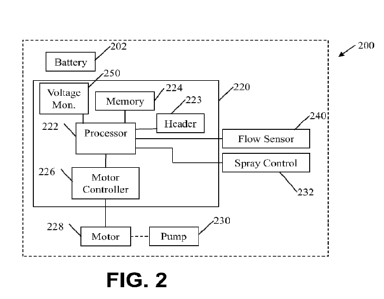
[0009] Figure 2 is simplified schematic diagram of another
exemplary embodiment of a
self-adjusting sanitizer/disinfectant sprayer having feedback control;
[0010] Figure 3 is simplified schematic diagram of yet another exemplary
embodiment of a
self-adjusting sanitizer/disinfectant sprayer having feedback control;
[0011] Figure 4 is a logic diagram for an exemplary embodiment for a self-
adjusting
sanitizer/disinfectant sprayer having feedback control;
100121 Figure 5 is a logic diagram for another exemplary embodiment
for a self-adjusting
sanitizer/disinfectant sprayer having feedback control;
[0013] Figure 6 is a logic diagram for another exemplary embodiment for a self-
adjusting
sanitizer/disinfectant sprayer having feedback control;
[0014] Figure 7 is simplified schematic diagram of another exemplary
embodiment of a
self-adjusting sanitizer/disinfectant sprayer having feedback control;
[0015] Figure 8 is simplified schematic view of another exemplary embodiment
of a
sanitizer/disinfectant sprayer having feedback control that may be self-
adjusting and/or may
provide one or more indications for a user to make adjustments;
100161 Figure 9 is a logic diagram for an exemplary embodiment of a
sanitizer/disinfectant
sprayer having feedback control that may be self-adjusting and/or may provide
one or more
indications for a user to make adjustments;
[0017] Figure 10 is simplified schematic view of another exemplary embodiment
of a
sanitizer/disinfectant sprayer having feedback control that may be self-
adjusting and/or may
provide one or more indications for a user to make adjustments;
3
CA 03218299 2023- 11- 7
WO 2022/240604
PCT/US2022/027258
100181 Figure 11 is simplified schematic view of another exemplary
embodiment of a self-
adjusting sanitizer/disinfectant sprayer having feedback control;
100191 Figure 12 is a logic diagram of another exemplary embodiment of a self-
adjusting
sanitizer/disinfectant sprayer having feedback control, and
100201 Figure 13 is a logic diagram of yet another exemplary embodiment of a
self-
adjusting sanitizer/disinfectant sprayer having feedback control.
DETAILED DESCRIPTION
100211 Exemplary embodiments for sanitizer/disinfectant sprayers having
feedback control
are disclosed herein.
100221 The following includes definitions of exemplary terms used throughout
the
disclosure. Both singular and plural forms of all terms fall within each
meaning. Except
where noted otherwise, capitalized and non-capitalized forms of all terms fall
within each
meaning:
100231 "Circuit communication" as used herein indicates a communicative
relationship
between devices. Direct electrical, electromagnetic and optical connections
and indirect
electrical, electromagnetic and optical connections are examples of circuit
communication.
Two devices are in circuit communication if a signal from one is received by
the other,
regardless of whether the signal is modified by some other device. For
example, two devices
separated by one or more of the following -- amplifiers, filters,
transformers, optoi solators,
digital or analog buffers, analog integrators, other electronic circuitry,
fiber optic transceivers
or satellites -- are in circuit communication if a signal from one is
communicated to the other,
even though the signal is modified by the intermediate device(s). As another
example, an
electromagnetic sensor is in circuit communication with a signal if it
receives electromagnetic
radiation from the signal. As a final example, two devices not directly
connected to each
other, but both capable of interfacing with a third device, such as, for
example, a CPU, are in
circuit communication.
100241 Also, as used herein, any voltages and values representing
digitized voltages are
considered to be equivalent for the purposes of this application, and thus the
term "voltage"
as used herein refers to either a signal, or a value in a processor
representing a signal, or a
value in a processor determined from a value representing a signal.
4
CA 03218299 2023- 11- 7
WO 2022/240604
PCT/US2022/027258
100251
"Signal", as used herein includes, but is not limited to one or more
electrical signals,
analog or digital signals, one or more computer instructions, a bit or bit
stream, or the like.
100261 "Logic," synonymous with "circuit," as used herein includes, but is not
limited to
hardware, firmware, software and/or combinations of each to perform a
function(s) or an
action(s). For example, based on a desired application or needs, logic may
include a software
controlled microprocessor or microcontroller, discrete logic, such as an
application specific
integrated circuit (ASIC) or other programmed logic device. Logic may also be
fully
embodied as software. The circuits identified and described herein may have
many different
configurations to perform the desired functions.
100271 Values identified in the detailed description are exemplary and they
are determined
as needed for a particular dispenser and/or refill design. Accordingly, the
inventive concepts
disclosed and claimed herein are not limited to the particular values or
ranges of values used
to describe the embodiments disclosed herein.
100281 Figure 1 is simplified schematic view of an exemplary embodiment of a
self-
adjusting sanitizer/disinfectant sprayer 100 having feedback control.
In this exemplary
embodiment, self-adjusting sanitizer/disinfectant sprayer 100 includes a tank
102 for holding
sanitizer/disinfectant, a pump housing 104, a liquid feed conduit 164, a spray
wand 152,
outlet nozzle 156, feedback sensor 160, trigger 154 and cable 164. Tank 102
includes a
carrying handle 103. Pump housing 104 includes a battery power supply (not
shown), control
circuitry (not shown) and a pump (not shown). Cable 164 places the trigger 154
and sensor
160 in circuit communication with the control circuitry.
100291 In this exemplary embodiment feedback sensor 160 is a flow sensor. Flow
sensor
160 may be located proximate the end of wand 150 as illustrated, or it may be
located in the
pump housing 104, in liquid feed conduit 106, or any other location where it
is capable of
determining or sensing the flow rate of the fluid flowing out of nozzle 156.
100301
Figure 2 is simplified schematic diagram of an exemplary embodiment of
self-
adjusting sanitizer/disinfectant sprayer 200 having feedback control.
Self-adjusting
sanitizer/disinfectant sprayer 200 includes a battery power pack 202. Battery
power pack 202
provides power to control circuitry 220, flow sensor 240, motor controller
226, motor 228
and any other device that requires power. The term "battery pack" should be
construed
broadly to mean one or more batteries. When more than one battery are include
in the battery
CA 03218299 2023- 11- 7
WO 2022/240604
PCT/US2022/027258
pack, the one or more batteries may be connected in series, may be connected
in parallel, or
combinations thereof.
100311 In some embodiments, battery power pack 202 or control circuitry 220
includes
voltage regulation circuitry (not shown). In some embodiments, the voltage
regulation
circuitry is included in system circuitry 220. One or more components shown on
system
circuitry 220 may be mounted on a common circuit board and/or may be
separately mounted
and placed in circuit communication with the required other components.
100321 Processor 222 may be any type of processor, such as, for
example, a microprocessor
or m i crocontrol 1 er, discrete logic, such as an application specific
integrated circuit (A SIC),
other programmed logic devices or the like. Processor 222 is in circuit
communication with
optional header 223. Header 223 is a circuit connection port that allows a
user to connect to
system circuitry 220 to program the circuitry, run diagnostics on the
circuitry and/or retrieve
information from the circuitry.
100331 Processor 222 is in circuit communication with memory 224. Depending on
the
need, memory 224 may be any type of memory, such as, for example, Random
Access
Memory (RAM); Read Only Memory (ROM); programmable read-only memory (PROM),
electrically programmable read-only memory (EPROM), electrically erasable
programmable
read-only memory (EEPROM), flash, magnetic disk or tape, optically readable
mediums
including CD-ROM and DVD-ROM, or the like, or combinations of different types
of
memory. In some embodiments, the memory 224 is separate from the processor
222, and in
some embodiments, the memory 224 resides on or within processor 222.
100341 Processor 222 is in circuit communication with motor
controller 226. Motor
controller 226 may be any type of circuitry used to control motor 228.
Preferably, motor
controller 226 utilizes pulse width modulation control to control the speed of
motor 228. A
detailed description of pulse width modulation control may be found in
Applicants co-
pending U.S. Pat. Application Serial No. 16/176,411, which is titled TOUCH-
FREE
DISPENSERS and was filed on October 31, 2018; and also in Applicants U.S. Pat.
Pub. No.
2017-0049276 title POWER SYSTEMS FOR DYNAMICALLY CONTROLLING A
SOAP, SANITIZER OR LOTION DISPENSER DRIVE MOTOR, each of which is
incorporated herein by reference in their entirety.
6
CA 03218299 2023- 11- 7
WO 2022/240604
PCT/US2022/027258
100351 In this exemplary embodiment, system circuitry 220 includes optional
voltage
monitoring circuitry 250 which monitors the voltage of battery pack 202. As
discussed in
more detail below, voltage monitoring circuitry 250 may be used by processor
222 to cut-off
operation of sanitizer/disinfectant sprayer 200 when the voltage output of the
battery pack
falls below about 3 volts, or falls below about 2.8 volts; or falls below
about 2.5 volts; or falls
below about 2 volts. In some embodiments, voltage monitoring circuitry 250 may
be used
by processor 222 to cut-off operation of sanitizer/disinfectant sprayer 200
when the voltage
output of the battery pack falls below a set percentage of the full charge
rating of the battery
pack, such as, for example, 50% of the rated capacity, 45% of the rated
capacity, 40% of the
rated capacity, 35% of the rated capacity, 30% of the rated capacity, 33% of
the rated
capacity 25% of the rated capacity, or 20% of the rated capacity. In some
embodiments,
processor 222 prevents operation of the sprayer if the battery voltage is
below any of the
above identified ranges. The voltages or capacities are above a threshold at
which the battery
stops providing enough power to power the motor. In some embodiments, the
threshold is
selected so that the flow rate is at least about 95% of the flow rate of a
fully charged battery.
In some embodiments, the threshold is selected so that the flow rate is at
least about 90% of
the flow rate of a fully charged battery. In some embodiments, the threshold
is selected so
that the flow rate is at least about 85% of the flow rate of a fully charged
battery. In some
embodiments, the threshold is selected so that the flow rate is at least about
80% of the flow
rate of a fully charged battery. In some embodiments, the threshold is
selected so that the
flow rate is at least about 75% of the flow rate of a fully charged battery.
In some
embodiments, the threshold is selected so that the flow rate is at least about
70% of the flow
rate of a fully charged battery.
100361 Processor 222 provides one or more outputs to motor controller 226,
which drives
motor 228. Motor 228 drives pump 230, or drives an actuator (not shown) and/or
one or
more gears that drives pump 230. In some embodiments, motor controller 226 is
designed to
provide consistent power to the motor 228 irrespective of the actual voltage
of the battery
pack 202. In some embodiments, pulse width modulation circuitry is used to
accomplish
consistent power. In some embodiments, when the charge of the battery pack is
high, the
voltage pulse width delivered to the motor 228 is short. As the charge of the
battery pack
decreases, the voltage pulse width delivered to the motor 228 is lengthened.
Accordingly, the
speed of the motor 228 may be controlled or maintained irrespective of the
charge on the
battery pack 202.
7
CA 03218299 2023- 11- 7
WO 2022/240604
PCT/US2022/027258
100371 Processor 232 is in circuit communications with spray control 232.
Spray control
232 initiates dispensing or spraying of sanitizer/disinfectants. Spray control
232 may be a
trigger on a dispensing wand (not shown) that is used to direct
sanitizer/disinfectant onto
desired surfaces. In some embodiments, spay controller 232 may be a button,
voice activated
controller, a switch, or the like, Spray control 232 may be hard wired to
system circuitry 220.
In some embodiments, system circuitry 220 includes optional wireless
communications
circuitry (not shown) or receiving and/or transmitting signals to one or more
devices. In
some embodiments, the dispensing wand (not shown) includes wireless
communications
circuitry for transmitting and/or receiving signals. In some embodiments, a
trigger (not
shown) on a dispensing wand (not shown) is in wireless circuit communications
with
processor 222.
[0038] A flow sensor 240 is also in circuit communications with processor 222.
Flow
sensor 240 is used to monitor the flow of sanitizer/disinfectant that is
flowing out of the
sprayer wand (not shown). Flow sensor 240 may be any sensor that senses flow
of fluid
flowing through and/or out of the system. In some embodiments, flow sensor 240
is an in-
line flow sensor, i.e flow sensor 240 directly monitors the flow through a
fluid conduit
and/or portion of the wand. Exemplary flow sensors include, differential
pressure flow
meters, positive displacement flow meters, velocity flow meters, mass flow
meter, turbine
meters, ultrasonic meters, and the like. In addition, flow sensor 240 may be
an optical flow
sensor. The optical flow sensor may use an optical sensor to detect droplet
size, droplet
velocity or the like that is indicative of the fluid flow rate.
[0039] In some embodiments, it is important to control the flow rate of the
fluid that is
flowing out of the sprayer wand. The flow rate has direct impact on, for
example, droplet
size, spray distance, volumes of fluid sprayed per unit of time, size of a
spray patch on a
surface, evenness of spray and the like. During operation, processor 222
receives a signal
indicative of the flow rate from flow sensor 240. If the flow rate is below a
selected
threshold, the processor 222 provides instructions for the motor controller
226 to increase the
speed of the motor 228. If the flow rate is above a selected threshold, the
processor 222
provides instructions for the motor controller 226 to decrease the speed of
the motor 228.
[0040] In some embodiments, flow sensor 240 is optional. In those embodiments,
processor 222 cuts off power to the motor 228 if the voltage monitoring
circuitry determines
that the voltage or power of the battery 202 is below a selected power
threshold or voltage
8
CA 03218299 2023- 11- 7
WO 2022/240604
PCT/US2022/027258
threshold, such as, for example, the % rated capacities identified above, or
the voltages
identified herein. The thresholds are selected to be above a threshold where
the battery stops
providing enough power to turn the motor.
100411 Figure 3 is simplified schematic diagram of an exemplary
embodiment of a self-
adjusting sanitizer/disinfectant sprayer 300 having feedback control.
Sanitizer/disinfectant
sprayer 300 is similar to self-adjusting sanitizer/disinfectant sprayer 200
and components
with the same reference numbers are not redescribed with respect to this
exemplary
embodiment. Flow sensor 240 has been replaced by optic sensor 310. Optic
sensor 310
captures spray pattern images. The spray pattern images may be compared to
spray pattern
images stored in the memory 224. Each stored spray pattern image may correlate
to a
selected motor speed. In some embodiments, a selected spray pattern image may
be chosen
or preset for the sprayer. If the spray pattern detected by optic sensor 310
is different from
the desired spray pattern, processor 222 increases or decreases the speed of
the motor to
arrive at the desired spray pattern. In some embodiments, the processor
increases the speed
of the motor and determines if the detected spray pattern image is getting
closer to the
selected spray pattern or further away from the selected spray pattern. If the
detected spray
pattern is getting closer to the selected spray pattern, the processor 222
continues to increase
the speed until the detected spray pattern is close to the selected spray
pattern. If the detected
spray pattern is getting further away from the selected spray pattern,
processor 222 decreases
the speed of the motor until the detected spray pattern is close to the
selected spray pattern
100421 The exemplary methodologies described herein contain a number of blocks
or steps.
Additional blocks or steps may be added to these exemplary embodiments. In
addition, some
blocks or steps may be removed from the exemplary methodologies. Further,
blocks or steps
from exemplary methodologies disclosed herein may be included in other
methodologies or
logic diagrams disclosed herein. In addition, unless expressly stated
otherwise, the order in
which the steps are performed is not critical and may be changed.
100431 Figure 4 is a logic diagram or methodology for controlling an exemplary
embodiment of a self-adjusting sanitizer/disinfectant sprayer having feedback
control. The
exemplary logic diagram begins at block 402. At block 404 a determination is
made as to
whether a request for the sprayer to spraying fluid has been initiated. If
there is no request,
the methodology loops back to block 402. If a request to spray fluid has been
initiated, the
methodology flows to block 408 to obtain data indicative of the spray flow
rate. A
9
CA 03218299 2023- 11- 7
WO 2022/240604
PCT/US2022/027258
determination is made at block 410 as to whether the flow rate is within a
selected threshold.
Exemplary thresholds may be, for example, within 0.05%, within 0.1%, within
0.5%, within
1%, within 2%, within 3%, within 4%, within 5%, or within 10%. In some
exemplary
embodiments, flow rate is estimated based on motor speed, and the threshold
may be applied
to the speed of the motor. If the flow rate is within the threshold,
the exemplary
methodology loops back to block 402. If the flow rate is outside of the
threshold, the
exemplary methodology flows to block 412 wherein the speed of the motor is
adjusted to
bring the flow rate back to being within the selected threshold. Preferably
this methodology
is continuous throughout the spraying operation. In some embedment's, the
methodology is
used periodically, such as, for example, ever 10 seconds, every 20 seconds,
every minute of
operation. Preferably, the methodology begins each time the sprayer is
activated.
100441 Figure 5 is another logic diagram or methodology 500 for controlling an
exemplary
embodiment of sanitizer/disinfectant sprayer having feedback control. The
exemplary logic
diagram begins at block 502. At block 504 a determination is made as to
whether the sprayer
is spraying fluid. If the sprayer is not spraying fluid, the methodology loops
back to block
502. If the sprayer is spraying fluid, the methodology flows to block 508 to
obtain data
indicative of the spray flow rate. A determination is made at block 510 as to
whether the
flow rate is within a selected threshold. Exemplary thresholds have been
described above.
If the flow rate is within the threshold, the exemplary methodology loops back
to block 502.
If the flow rate is outside of the threshold, the exemplary methodology flows
to block 512
where a determination is made as to whether the voltage of the battery pack is
above a cut-off
voltage. If the voltage is above the cut-off voltage, the exemplary
methodology flows to
block 514 and the speed of the motor is adjusted. If it is determined that the
battery pack
voltage is not above the cut-off voltage, the exemplary methodology flows to
block 516 and
the sprayer is disabled or prevented from operating.
100451 Figure 6 is another logic diagram or methodology for controlling an
exemplary
embodiment of sanitizer/disinfectant sprayer having feedback control. The
exemplary logic
diagram begins at block 602. At block 604 a determination is made as to
whether the sprayer
is spraying fluid. If the sprayer is not spraying fluid, the methodology loops
back to block
602. If the sprayer is spraying fluid, the methodology flows to block 608 to
obtain data
indicative of the spray flow rate. A determination is made at block 610 as to
whether the
flow rate is within a selected threshold. Exemplary thresholds have been
described above.
CA 03218299 2023- 11- 7
WO 2022/240604
PCT/US2022/027258
If the flow rate is within the threshold, the exemplary methodology loops back
to block 602.
If the flow rate is outside of the threshold, the exemplary methodology flows
to block 612
and a timer is started. The exemplary methodology flows to block 614 where a
determination
is made as to whether the timer is over the set time limit. If the timer is
not over the set time
limit, the methodology flows to block 616 wherein one or more parameters are
changed to
adjust the flow rate. At block 618 data indicative of the flow rate is
obtained and at block
620 a determination is made as to whether to flow rate is consistent with the
adjusted flow
rate If the flow rate is at the set point, the timer is reset at block 622 and
the methodology
flows to block 602. If the flow rate is not up to the adjusted flow rate, the
methodology loops
back to block 614 where a determination is made as to whether the timer has
timed out. If the
timer has timed out, the sprayer is disabled or prevented from operating at
block 630.
100461 Figure 7 is simplified schematic diagram of another exemplary
embodiment of a
self-adjusting sanitizer/disinfectant sprayer having feedback control.
Sanitizer/disinfectant
sprayer 700 includes a battery pack 202, a processor 222, memory 224, a motor
controller
226, a motor 228, a pump 230 and a spray controller 232. These components are
similar to
those described with respect to the embodiment shown in Figure 2 and described
in detail
above, and accordingly, are not redescribed in detail herein.
Sanitizer/disinfectant sprayer
700 includes a housing 702, a container 704 for holding sanitizer or
disinfectant. The
container 704 is in fluid communication with the pump 230, which is in fluid
communication
with the spray nozzle 782. One or more valves, such as, for example, one-way
valves may be
incorporated into the flow path. In addition, Sanitizer/disinfectant sprayer
700 includes a
time of flight ("TOF") sensor 780, or a distance sensor, in circuit
communications with
processor 222. The TOF sensor 780 is located in the wand 750. The TOF sensor
780
measures the distance to a target in front of the wand 780 and provides a
signal indicative of
the distance to the processor 222. Processor 222 utilizes the signal to
control the speed of the
motor and/or the flow rate of the fluid to the wand 750.
100471 In some embodiments, the Sanitizer/disinfectant sprayer 700 is
configured to
dispense fluid at a first flow rate that is set for a targeted distance. The
TOF sensor 780
determines the distance to an object that is in front of the wand 750. The
object, may be, for
example, a wall, a desk, a counter, a device, or the like. If the TOF sensor
780 detects a
distance to the object that is less than the targeted distance, processor 222
reduces the flow
rate of fluid to the wand 750. If the TOF sensor 780 detects a distance to the
object that is
11
CA 03218299 2023- 11- 7
WO 2022/240604
PCT/US2022/027258
greater than the targeted distance, processor 222 increases the flow rate of
fluid to the wand
750. In some embodiments, if the TOF sensor 780 detects that the object is
outside a selected
range, processor 222 prevents sanitizer/disinfectant sprayer 700 from spraying
fluid.
100481 In some embodiments, if the TOF sensor 780 senses a rapid change in
distance,
processor 222 stops sanitizer/disinfectant sprayer 700 from spraying fluid.
This feature is
useful in preventing overspray which is a waste of sanitizer/disinfectant and
also may lead to
slipping hazards. For example, if a janitor is sanitizing or disinfecting
desks in a class room,
when the wand 750 gets to the end of the desk, the sanitizer/disinfectant
sprayer 700 shuts off
and stops dispensing sanitizer or disinfectant as soon as the TOF sensor 780
detects a rapid
change in distance, i.e. the wand 750 passed over the end of the desk.
100491 Figure 8 is simplified schematic diagram of another
exemplary embodiment of
sanitizer/disinfectant sprayer having feedback control. Sanitizer/disinfectant
sprayer 800 is
similar to sanitizer/disinfectant sprayer 700 and like components are not
redescribed herein.
Sanitizer/disinfectant sprayer 800 includes an accelerometer 802 located in
wand 850.
Accelerometer is in circuit communications with processor 222. Accelerometer
802 provides
a feedback signal to processor 222. Processor 222 may use the feedback signal
to increase or
decrease the flow rate of the sanitizer or disinfectant solution. For example,
if the
accelerometer 802 signal indicates a rapid acceleration, processor 222
increases the flow rate.
If the accelerometer 802 signal indicates a rapid deceleration, processor 222
may decrease the
flow rate. The accelerometer 802 may be useful for applications where the
operator is using
sweeping motions to disinfect a surface, such as, for example, a counter top
or table.
100501 In addition, sanitizer/disinfectant sprayer 800 includes one
or more optional
indicators 860. One or more optional indicators 860 may provide a visual,
audible, and/or
haptic signal to the operator of the sanitizer/disinfectant sprayer 800. Thus
in this exemplary
embodiment, the sprayer 800 may be a "self-adjusting" by directing an operator
to make
adjustments in the operator's use of the sprayer. Such indicators, may
include, for example,
one or more lights, such as a green light and a red light. The green light may
indicate that the
operator is moving within a desired speed range, while the red light may
indicate operation
outside of the desired speed range. In some embodiments, a first light (e.g.
yellow light)
means that the operator has the wand 850 too close to the surface, a second
light (e.g. an
orange light) means that the operator is too far away from the surface, and a
third light (e.g. a
blue light) means the operator has the wand 850 a correct distance from the
surface.
12
CA 03218299 2023- 11- 7
WO 2022/240604
PCT/US2022/027258
100511 Audible indicators may be, for example, a voice synthesizer that
provides audible
messaging to the operator to change an application characteristic, such as,
for example,
speed, consistency, motion, and the like. Similarly the haptic signal may
provide, for
example, a vibratory sensation in the wand if the operator is operating
outside of one or more
characteristics. In some embodiments, two short vibrations may mean that the
operator is
moving too fast and one long vibration may mean the operator is moving to
slow.
[0052] The one or more indicators 860 may be training indicators that are used
to teach or
remind operators of the proper use of the sanitizer/disinfectant sprayer 800.
[0053] The one or more indicators 860 may be in a housing 862. The housing 862
may be
attached to the sprayer housing 702, the wand 850, or the operator. In some
embodiments,
housing 862 is in the form of a wearable device, such as, for example, a
badge, a smart
phone, or the like.
[0054] Figure 9 is simplified schematic diagram of another
exemplary embodiment of a
self-adjusting sanitizer/disinfectant sprayer having feedback control.
Sanitizer/disinfectant
sprayer 900 is similar to sanitizer/disinfectant sprayer 800 and like
components are not
redescribed herein. Sanitizer/disinfectant sprayer 900 includes a LiDar sensor
902 in circuit
communications with processor 222. In addition, sanitizer/disinfectant sprayer
900 includes
an optional nozzle adjuster 904 in circuit communication with processor 222.
[0055] LiDar sensor 902 utilizes pulsed laser signals to generate a 3-D image
of an area in
its field of view, such as, for example, an object that is being sanitized and
or disinfected.
Accordingly, processor 222 may be configured to increase or decrease the flow
rate of
sanitizer or disinfectant that is being applied to the surface of the object.
The increase or
decrease may be a function of distance to points on the surface of the object,
speed at which
the wand is moving, or the like.
[0056] Optional nozzle adjuster 904 may be used by processor 222 to adjust the
droplet size
being applied to the object. In some examples, if an object surface is close
to the wand 950,
processor uses nozzle adjuster to adjust the nozzle to deliver finer droplet
sizes on the
surface. As the wand 950 is moved away from the surface, processor 222 uses
nozzle
adjuster to increase the droplet size that is being dispensed.
13
CA 03218299 2023- 11- 7
WO 2022/240604
PCT/US2022/027258
100571 Figure 10 is simplified schematic diagram of another exemplary
embodiment of a
self-adjusting sanitizer/disinfectant sprayer having feedback control.
Sanitizer/disinfectant
sprayer 1000 is similar to sanitizer/disinfectant sprayer 900 and like
components are not
redescribed herein. Sanitizer/disinfectant sprayer 1000 includes a multi-
sensor 1002 in
circuit communications with processor 222. Multi-sensor 1002 may be one or
more sensors.
Multi-senor 1002 includes one or more of an accelerometer, a gyroscope, a
magnetometer, a
velocimeter, a time of flight sensor, a distance sensor or the like.
In this exemplary
embodiment, processor 222 may precisely control the volume of fluid being
dispensed on the
surface of an object and may precisely stop dispensation of fluid as the wand
1050 travels
past the ends of the objects. Very precise control of the fluid is possible
because processor
222 can determine multiple variables, including two or more of acceleration,
orientation,
velocity, and distance to the object that is being sanitized or disinfected.
100581
Figure 11 is simplified schematic view of another exemplary embodiment
of
sanitizer/disinfectant sprayer 1100 having feedback control.
Sanitizer/disinfectant sprayer
1100 includes a tank 1110 for holding sanitizer/disinfectant, a pump house
1112, a handle
1114, disinfectant/sanitizer fluid conduit 1114, a spray wand 1112 and a
feedback sensor
1120. These components may be similar to like components described above.
Feedback
sensor 1120 may be any of the sensors described above. In some embodiments,
feedback
sensor 1120 includes a distance sensor. In some embodiments, feedback sensor
includes one
or more of an accelerometer, a gyroscope, a magnetometer a yelocimeter, or the
like. In this
exemplary embodiment, feedback sensor 1120 may detect a distance D1 to an
object 1140. A
processor (not shown) located in the pump house 1112 adjusts the flow rate of
sanitizer/disinfectant flowing out of the dispensing wand 1112. The flow rate
may be set as a
function of the distance Dl. In this exemplary embodiment, as dispensing wand
1112 moves
past the edge of object 1140, feedback sensor 1120 detects an abrupt increase
in distance to
distance D2 and the processor (not shown) stops fluid flow, which prevents
overspray. If the
user moves the dispensing wand 1112 back down, distance D1 is detected and the
processor
starts fluid flow (provided that the trigger (not shown) is pressed. In some
embodiments,
feedback sensor 1120 can sense a sweeping motion Si. In such an embodiment,
the
processor (not shown) may increase and decrease flow as a function of the
location of the
dispensing wand 1112 in the sweep Si. In some embodiments, feedback sensor
1120 detects
acceleration and deceleration and increases and decreases flow accordingly.
14
CA 03218299 2023- 11- 7
WO 2022/240604
PCT/US2022/027258
100591 Figure 12 is a logic diagram or methodology 1200 for an exemplary
embodiment of
sanitizer/disinfectant sprayer having feedback control from one or more
sensors. The
exemplary methodology begins at block 1202 when a user activates the sprayer.
The sprayer
may be activated by, for example, squeezing a trigger. When the user releases
the trigger, or
deactivates the sprayer, the methodology may stop. At block 1204 a distance to
the targeted
object is obtained. In some embodiments, the targeted object is directly in
front of the
sprayer wand. The distance to target object may be determined by a time of
flight (TOF)
sensor or other distance sensor. Based on the detected distance, a processor
in the sprayer
sets the initial fluid delivery parameters and begins applying fluid to the
targeted object. The
fluid delivery parameters, or fluid dispensing properties, may be, for
example, fluid flow rate,
droplet size, nozzle settings, pressure settings, spray patterns, or the like.
At block 1208 the
distance to the target object is again determined. At block 1210, a
determination is made as
to whether the target is in range. If the target is not in range, an
assumption is made that the
user's intention is for broad projection of spray with delivery falling onto
surfaces below and
the fluid deliver parameters are modified at block 1212 for broad projection
delivery. The
exemplary methodology loops back to block 1208.
100601 If at block 1210 an in-range target is detected the
methodology proceeds to block
1214. Several parameters may be monitored at block 1214, including but not
limited to, one
or more of: TOF using, for example, a time of flight sensor; azimuth
horizontal angular
position using, for example, a digital compass IC sensor; acceleration in the
horizontal
direction, using, for example, an accelerometer; and acceleration inclination,
using, for
example, an accelerometer. At block 1216, the data is evaluated and apparent
swipe velocity
and acceleration are calculated. In addition, in some embodiments,
environmental factors
may be included in the calculations. The environmental factors, may be, for
example, school,
office, hospital, doctors office, and the like.
100611 At block 1218 a determination is made as to whether a high swipe
velocity/acceleration was determined, or a low swipe acceleration was
determined. If a high
swipe acceleration is determined, an assumption is made at block 1220 that the
user is
rapidly changing targets. At block 1222, position forward in time is
extrapolated based on
velocities and accelerations and the fluid delivery parameters are modified at
block 1222 to
spray fluid with fluid delivery parameters desired for rapidly changing
targets and the
methodology loops back to block 1208.
CA 03218299 2023- 11- 7
WO 2022/240604
PCT/US2022/027258
100621 If at block 1218 a determination is made that a low swipe
velocity/acceleration was
determined, an assumption is made that the user is focusing on the targeted
object. At block
1224, position forward in time is extrapolated based on velocities and
accelerations and the
fluid delivery parameters are modified at block 1226 to spray fluid with fluid
delivery
parameters desired for directed targets and the methodology loops back to
block 1208.
100631 Figure 13 is a logic diagram or methodology 1300 for an exemplary
embodiment of
sanitizer/disinfectant sprayer having feedback control from a Lidar sensor.
The exemplary
methodology begins at block 1302 when a user activates the sprayer. The
sprayer may be
activated by, for example, squeezing a trigger. When the user releases the
trigger, or
deactivates the sprayer, the methodology may stop. At block 1304, one or more
image scans
are med and a distance to the target is determined. At block 1306, initial
fluid delivery
parameters are set and the sprayer begins spraying fluid. At block 1308 a
distance to the
targeted object is determined. At block 1310 pattern recognition searches are
conducted for
planar surfaces in the field of view, e.g. wall, equipment's, office
furniture. In some
embodiments, the environment is also used in the calculations, such as, for
example, a school,
a hospital, a doctor's office, a restaurant and the like. For example, the
algorithm performing
the pattern recognition may search a data base of patterns for a particular
environment, such
as, for example, in a school setting, the data base may contain a number of
different desk
profiles that are common in school settings.
100641 At block 1312, a determination is made as to whether an in-
range target, such as a
wall or other dominate object, is detected. If no in range planar wall or
dominate object is
detected, an assumption is made at block 1314 the user intends for broad
projection with
delivery falling onto surfaces, and the fluid delivery parameters are modified
at block 13 14
accordingly and the sprayer dispenses fluid using those set parameters. The
exemplary
methodology flows back to block 1308.
100651 If at block 1312, a determination is made that an in-range target was
detected, a
determination is made at block 1320 of whether the surface is a planar
surface. If the surface
in range and not planer surface (not e.g. a wall, wall hanging window edge, or
the like) an
assumption is made at block 1322 that the user intends to deposit the
sanitizer/disinfectant on
the targeted object. At block 1322, one or more calculations are made. The one
or more
calculations may be a function of one or more of apparent swipe velocity,
acceleration,
distance change rate over time and accelerations. One or more of these
calculations may be
16
CA 03218299 2023- 11- 7
WO 2022/240604
PCT/US2022/027258
used to extrapolate positions forward in time. The fluid delivery parameters
are modified at
block 1324 to spray fluid with fluid delivery parameters in line with the one
or more
calculations or extrapolated positions forward in time to apply
sanitizer/disinfectant to the
directed targets and the methodology loops back to block 1308.
100661 If at block 1320 a planar surface is in range, a determination is made
at block 1330
to determine whether a dominate object is found in the field of view. Examples
of dominate
objects may be, for example, wall hanging, window edge, chair, etc. If a
dominate object is
found, an assumption is made that the target is the dominate object. At block
1332, one or
more calculations are made. The one or more calculations may be a function of
one or more
of apparent swipe velocity, acceleration, distance change rate over time and
accelerations.
One or more of these calculations may be used to extrapolate positions forward
in time. The
fluid delivery parameters are modified at block 1334 to spray fluid with fluid
delivery
parameters in line with the one or more calculations or extrapolated positions
forward in time
to apply sanitizer/disinfectant to the dominate object and the methodology
loops back to
block 1308.
100671 If at block 1330 a determination is made that no dominate object is
found in the field
of view an assumption is made that the target is an empty or flat wall. At
block 1340, one or
more calculations are made. The one or more calculations may be a function of
one or more
of apparent swipe velocity, acceleration, distance change rate over time and
accelerations.
One or more of these calculations may be used to extrapolate positions forward
in time The
fluid delivery parameters are modified at block 1342 to spray fluid with fluid
delivery
parameters in line with the one or more calculations or extrapolated positions
forward in time
to apply sanitizer/disinfectant to the planar surface and the methodology
loops back to block
1308.
100681 The term hand-held and portable sprayer is meant to include portable
sprayers that
are carried around by a person during used. As such, sprayers, such as, for
example, a
backpack sprayer, considered to fall within the term hand-held portable
sprayer.
100691 While various inventive aspects, concepts and features of the
inventions may be
described and illustrated herein as embodied in combination in the exemplary
embodiments,
these various aspects, concepts and features may be used in many alternative
embodiments,
either individually or in various combinations and sub-combinations thereof.
It is not the
17
CA 03218299 2023- 11- 7
WO 2022/240604
PCT/US2022/027258
intention of the applicant to restrict or in any way limit the scope of the
appended claims to
such detail. Unless expressly excluded herein, all such combinations and sub-
combinations
are intended to be within the scope of the present inventions. Still further,
while various
alternative embodiments as to the various aspects, concepts and features of
the inventions --
such as alternative materials, structures, configurations, methods, circuits,
devices and
components, software, hardware, control logic, alternatives as to form, fit
and function, and
so on -- may be described herein, such descriptions are not intended to be a
complete or
exhaustive list of available alternative embodiments, whether presently known
or later
developed. Those skilled in the art may readily adopt one or more of the
inventive aspects,
concepts or features into additional embodiments and uses within the scope of
the present
inventions even if such embodiments are not expressly disclosed herein.
Additionally, even
though some features, concepts or aspects of the inventions may be described
herein as being
a preferred arrangement or method, such description is not intended to suggest
that such
feature is required or necessary unless expressly so stated. Still further,
exemplary or
representative values and ranges may be included to assist in understanding
the present
disclosure; however, such values and ranges are not to be construed in a
limiting sense and
are intended to be critical values or ranges only if so expressly stated.
Moreover, while
various aspects, features and concepts may be expressly identified herein as
being inventive
or forming part of an invention, such identification is not intended to be
exclusive, but rather
there may be inventive aspects, concepts and features that are fully described
herein without
being expressly identified as such or as part of a specific invention.
Descriptions of
exemplary methods or processes are not limited to inclusion of all steps as
being required in
all cases, nor is the order in which the steps are presented to be construed
as required or
necessary unless expressly so stated.
18
CA 03218299 2023- 11- 7