Note: Descriptions are shown in the official language in which they were submitted.
CA 03218522 2023-10-30
WO 2022/243974
PCT/IB2022/054752
1
PERMANENT MAGNETS WITH INTEGRATED PHASE CHANGE MATERIALS
FIELD
[0001] The present disclosure relates generally to permanent magnets for use
in
electric machines. In particular, the present disclosure relates to permanent
magnets for use in electric machines containing phase change material
integrated
with the permanent magnet.
BACKGROUND
[0002] Canadian Patent Application 2,118,539 to Muhlberger etal. teaches an AC
generator having, in some embodiments, phase transition materials incorporated
into insulating rings of a rotor, proximal to permanent magnetic (PM)
materials. The
rotor includes alternating rings of PM and enclosures for PCMs. Applicant
takes
'phase transition materials' to be synonymous with phase change materials
(herein
PCMs). The challenges of incorporating PCMs directly into PMs is not
addressed,
nor addressable by, Muhlberger etal., and consequently substantially less
effective
cooling is produced. For cooling, high-surface-area direct contact to a heat
sink is
vastly superior to coupled, remote, contact.
[0003] This section is intended to introduce various aspects of the art, which
may
be associated with the present disclosure. This discussion is believed to
facilitate a
better understanding of particular aspects of the present disclosure.
Accordingly, it
should be understood that this section should be read in this light, and not
as
admissions of prior art.
[0004] Magnetic performance of permanent magnets such as NdFeB permanent
magnets used in electric motors are known to rapidly decrease as operating
temperature increases. This limits the power output of motors as their
operating
temperature rapidly increases with increasing power demand. This is
particularly
problematic for applications where high peak power is required for relatively
short
periods of time, for example during a highway acceleration or during an
airplane's
take-off.
[0005] It is well known that higher grade magnets ¨ typically composed
of a
higher fraction of heavy rare earth elements (e.g. Dy or Tb) ¨ are less prone
to
CA 03218522 2023-10-30
WO 2022/243974
PCT/IB2022/054752
2
demagnetization and thus withstand higher maximum operating temperatures.
Higher grade magnets are more expensive and their price is volatile.
Furthermore,
even the highest grade of NdFeB magnets have maximum operation temperature
around 170 C. Therefore it is desirable to employ temperature rise limiting
(TRL)
strategies in electric machines. TRL strategies typically include cooling
systems
provided by thermal fluid circulation (typically liquid), that is limited to
features in
stators of electric machines as it is impractical to route a liquid in a rotor
part
operating at a variety of speeds up to several thousand RPM. TRL strategies
for
the rotor component usually relies on the natural heat transfer between the
rotor
and cooled stator. It is known, as explained hereinabove, to prevent rotor
overheating with PCMs, but integration of PCMs within PMs, is not known.
[0006] It follows that costs of motor manufacture are strongly affected by
material
costs of magnets. Design possibilities are restricted by the shape and
positioning
of magnets that can be provided by the manufacturing techniques.
Conventionally
PMs are produced by powder metallurgical forming and sintering, however these
methods do not admit formation on rotors and therefore a separate step of
mounting
the PMs to the rotor is typically required: mounting is typically provided by
adhesives, slotting or screws. Handling, aligning, bonding and machining the
PMs
is limited by their mechanical properties.
[0007] For current purposes, the principal shortcoming of PM materials formed
by
powder metallurgy is their combination of low ultimate tensile strength,
brittleness
and low ductility, which herein is termed frangibility. The frangibility of
typical high
grade PM materials introduces many practical and cost limitations on design
and
feature size and geometry that can be mounted to rotors in low-cost, fast,
quality-
assured processes. Thus fabrication cost, machining limitations and mechanical
integrity requirements lead to relatively simple, somewhat stubby, PM shapes.
[0008] These shape limitations are most troublesome for designing integrated
TRL
systems, regardless of method of assembly of the PM components. TRL
inherently,
and unavoidably, produces a temperature gradient locally within the PM, which
can
increase thermal stresses. Providing cavities and recesses that bring the PCM
in
CA 03218522 2023-10-30
WO 2022/243974
PCT/IB2022/054752
3
most intimate contact with PM materials (where thermal control is most in
need) can
produce thin necks of PM materials that increase risks of fracture.
[0009] The use of additive manufacturing (AM), and particularly cold spray
additive
manufacturing (CSAM), to form PM parts can address many issues. CSAM can co-
deposit a metal like Cu or Al (or alloys thereof) along with a PM powder at a
rate of
several kg/hour. The metal incorporated into the material improves deposition
efficiency, and produces PMs with improved thermal conductivity, and greatly
reduced frangibility. CSAM can build up PM parts directly onto rotors, and can
provide high adhesion strength, and high reliability thereof. Deposition on
the rotors
themselves avoids a complex assembly step. Any problems with adhesives or
assembly, which can limit heat transfer from PM to rotor, or can intrude into
PCM
cavities, are avoided. Design of the PM can provide for more strategic
localization
of PM materials, with less risk of delamination or separation of the PM from
the
rotor. Many of the assembly risks, much of the workload, and the design
limitations
can be avoided with these less frangible, and more reliably adhered PMs. The
use
of PM materials having higher resilience to stress is highly desirable for the
incorporation of more effectively positioned PCM within PMs, and the reduction
of
usage of expensive PM materials.
[0010] There therefore remains a need for an alternative approach to TRL in
general and for more effective local cooling of PMs in electric machines,
especially
in rotary elements.
SUMMARY
[0011] In an aspect of the present disclosure, there is provided a permanent
magnet (PM) for use in an electric machine, said PM containing a phase change
material (PCM) integrated within said PM, the PCM having a phase transition
temperature between about 80 C to about 200 C.
[0012] In respective embodiments, said PCM can be characterized as: having a
phase transition temperature between 150 C to about 250 C; having a latent
heat
of at least 50 kJ/kg; or composed of Paraffin, Erythritol or a combination
thereof.
CA 03218522 2023-10-30
WO 2022/243974
PCT/IB2022/054752
4
[0013] In an embodiment, the permanent magnet is composed of a hard magnetic
material comprising a hard magnetic phase, and a binder phase. In an
embodiment, said hard magnetic material consists essentially of an AINiCo
alloy, a
NdFeB alloy, a SmCo alloy, a SmFeCo alloy, or a combination thereof. In an
embodiment, the hard magnetic material consists essentially of NdFeB, a NdFeB
alloy, or a combination thereof. In an embodiment, the binder consists
essentially
of Al, Cu, Ti, Zn, Fe, Ni, Ag, Au, an alloy thereof, or a combination thereof,
more
preferably the binder comprises more Al, Cu, Zn, Ni or Fe than any other
element.
In an embodiment, the binder is Al, or an alloy thereof.
[0014] In an embodiment, the permanent magnet is composed of at least about
34 vol% hard magnetic phase, and at least 10 vol% of the binder, with at least
70%
of the composition consisting of the binder and hard magnetic phases. At least
51 vol% of hard magnetic phase is required for most applications, and around
75 vol% has been demonstrated in reasonably efficient processes, although
higher
volume fractions of hard magnetic phase are possible with some deposition
processes, for example as high as 85 vol%. Those skilled in the art will
recognize
that volume fraction of the hard magnetic phase can be increased to improve
magnet remanence, possibly at the expense of mechanical properties provided by
the metallic binder. Furthermore technological improvements are expected to
lead
to higher hard magnetic phase volume fraction with greater deposition
efficiency.
[0015] In respective embodiments, the PM contains one or more cavities in
which
the phase change material is integrated; such as 1 to 10, or 5 to 10 of said
cavities.
[0016] In an embodiment, each of the cavities is a blind, elongated chamber
extending from one side of the PM, having two smaller dimensions and a larger
dimension, the larger dimensions of each cavity are oriented substantially
mutually
in parallel, or each may be locally normal (within +/-15 ) to a surface of the
PM.
Each cavity may have a cylindrical, or a frustoconical shape, consistent with
production by drilling of the PM.
[0017] In another embodiment, each of the cavities extends a substantially
constant (e.g. +/- 15%) distance from the surface of the PM, be it on a
surface, or
a subsurface cavity.
CA 03218522 2023-10-30
WO 2022/243974
PCT/IB2022/054752
[0018] In an embodiment, the PM is mounted to a rotor for an electric machine.
To the extent that the cavities are elongated, they may preferably extend
parallel to
a rotor axis, or azimuthally (circumferentially) around the axis, as opposed
to
radially. The PM may be consistent with formation by AM, preferably with CSAM.
5 The rotor may be mounted to an axle and to a stator to produce an
electric machine.
[0019] In an embodiment, the permanent magnet is made by additive
manufacturing, such as cold spray additive manufacturing.
[0020] Another aspect of the disclosure is a method of manufacturing a
permanent
magnet, said method comprising: providing a permanent magnet material, and
forming the permanent magnet by additive manufacturing directly on a substrate
using the permanent magnet material; finishing the PM and producing or
finishing
a cavity within the PM for retaining a phase change material; integrating the
phase
change material into the permanent magnet; and enclosing the cavity.
[0021] In an embodiment of the method, said producing or finishing a cavity
comprises forming a cavity in said permanent magnet. In an embodiment, the
additive manufacturing further comprises: depositing said phase changing
material
in solid form, or depositing said phase changing material in powder form and
then
curing said powder, pouring phase changing material in liquid form and then
solidifying said liquid form. In an embodiment of the method, forming the
permanent
magnet comprises: sequentially building up the permanent magnet defining the
cavity using the permanent magnet material.
[0022] In an embodiment, enclosing the cavity further comprises closing said
cavities using a machined press-in or screw-in cap.
[0023] Other aspects and features of the present disclosure will become
apparent to those ordinarily skilled in the art upon review of the following
description
of specific embodiments in conjunction with the accompanying figures.
BRIEF DESCRIPTION OF THE DRAWINGS
[0024] Embodiments of the present disclosure will now be described, by
way of
example only, with reference to the attached figures, in which:
CA 03218522 2023-10-30
WO 2022/243974
PCT/IB2022/054752
6
[0025] FIG. 1a,b respectively depict a 2D schematic representation, and a 3D
model, of a half of a permanent magnet motor for an electric vehicle which may
be adapted in accordance with the present invention, the motor having 10 rotor
poles and 12 windings;
[0026] FIG. 2a depicts the torque speed curve of the motor of FIG. 1 as well
as
different motor operation points corresponding to different driving
conditions;
[0027] FIG. 2b depict different motor loss components for the operation
points;
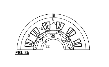
[0028] FIGs. 3a-c respectively depict a half motor assembly schematic
according to an embodiment of the invention, including principal motor parts,
said schematic labelled to identify different heat transfer hypotheses and air
gap
dimensions were used in simulations of embodiments of the present invention;
respectively illustrating a 3D model of the motor assembly, and side and top
views;
[0029] FIG. 4a is a schematic typical Heat Capacity vs. Temperature curve for
a phase changing material;
[0030] FIG. 4b is a bar chart showing ultimate tensile strength of cold
sprayed
additive manufactured PM materials in comparison to some other PM materials;
[0031] FIG. 5a is a graph showing the simulated average magnet side
temperature increase as a function of time during an uphill drive scenario,
with
and without the integrated PCM;
[0032] FIG. 5b shows the same feature of the same simulation system observed
during a highway acceleration scenario;
[0033] FIG. 6 depicts the simulated magnet temperature distribution after 15s
of uphill drive scenario with and without the integrated PCM;
[0034] FIG. 7 is a graph of magnet side temperature throughout a simulated
electric vehicle operating scenario where a motor is operated in steady state
one
hour, the motor is operated at a peak demand for 60 seconds, and then operated
in steady state again for another 1 hour duration; FIG. 7a shows an
enlargement
the graph of FIG. 7 providing a close-up view over the time period
corresponding
to the peak demand to clearly show the temperature reduction with the PCM;
CA 03218522 2023-10-30
WO 2022/243974
PCT/IB2022/054752
7
[0035] FIG. 8a shows the simulated average and maximum magnet
temperatures under the motor operating scenario presented in Fig. 7; FIG. 8b
shows a close-up view for the time period corresponding to the peak demand;
and FIG. 8c is a graph of a percentage of effective phase change material that
is
molten (above 118 C) during the high power demand period, showing that only
10.5% of the total PCM volume is effective in the PCM configuration of FIG.
9a,
in this scenario;
[0036] FIGs. 9a-c show 3 segmentation examples of the permanent magnet for
better TRL, according to an embodiment of the invention;
[0037] FIG. 10a is a multi-graph of a thermal transient analysis of the
permanent
magnet without PCM and the 3 segmentation examples of FIGs. 9a-c; FIG. 10b
is a histogram showing the transient time to reach 150 C for the 3
segmentation
examples of FIGs. 9a-9c; and FIG. 11 is a temperature distribution at a 90
second data point of the simulated process shown in FIG. 10a;
[0038] FIG. 12 is a panel comparing a segmented PM design with an integrated
cavity PM design according to an embodiment of the present invention; the
panel
comprising side-by-side, for the two PM designs: side elevation views,
temperature distributions during simulation at corresponding moments in a
scenario; and heat flux vector plots showing heat flux at corresponding
moments
in a scenario;
[0039] FIG. 13 is a temperature vs. time plot for the designs of FIG. 12,
illustrating the small difference provided by integration of the PCM into the
PM
for TRL purposes;
[0040] FIG. 14 is a side elevation view of a variant of the integrated cavity
PM
design featuring a rounded top surface, the cavities provided by bore holes
drilled
from two opposite sides, one of which being capped; and FIG. 14a is a cross-
sectional view of the PM design of FIG. 14, cut through line AA, showing an
arrangement of longitudinal cavities buried in the PM;
[0041] FIG. 15a is a schematic cross-sectional view through a second variant
of the PM design featuring 5 frustoconical cavities of two different sizes,
each
CA 03218522 2023-10-30
WO 2022/243974
PCT/IB2022/054752
8
provided as if bored by a tapered bit from a different respective angle, each
angle
being normal to a surface of the PM part; and FIG. 15b is an end view of the
PM
of FIG. 15a;
[0042] FIG. 16 is a schematic cross-sectional view showing a third variant PM
design featuring an elongated cavity recessed from a top (as shown) surface by
a constant distance, as well as two side cavities of variable, but
monotonically
decreasing diameter with distance from the respective side surfaces from which
they extend; and
[0043] FIG. 17 is a schematic section view showing a fourth variant PM design,
the fourth variant featuring two surface ridges running a fixed depth into
sides
(as shown) of the PM, and two low height fan shaped recesses extending as
blades into the middle of the PM.
[0044] It
should be noted that the figures are merely examples and no limitations
on the scope of the present disclosure are intended thereby.
DETAILED DESCRIPTION
[0045] As used
herein, the terms `PM(s)', 'magnet(s)' hard magnet(s)' and
'permanent magnet(s)' are used interchangeably to refer to (a) permanent
magnet(s).
[0046] As used
herein, `NdFeB' refers to a hard magnetic material of, or for
forming, a PM part, and may be otherwise represented as `FeNdB', or any other
order (or ratio) of the elements Nd, Fe, and B. In some embodiments, other
elements may be added to the hard magnetic powder NdFeB to control particular
properties, such as high temperature stability.
[0047] As used herein, ?CM' refers to a phase change material.
[0048] As used herein, 'TRU refers to temperature rise limiting, an
adjective
qualifying a system, strategy or structure that reduces a tendency to a PM
overheating during operation, particularly at high torque loads, or over
bursts, or
short periods of, high heat output.
[0049]
Generally, the present disclosure provides a PM containing a phase
changing material integrated therein. The phase changing material may limit
the
CA 03218522 2023-10-30
WO 2022/243974
PCT/IB2022/054752
9
temperature rise of the PM during operation. The PM can be used in
applications
such as electric machines and in particular electric motors. The electric
motors may
be used in electric ground vehicles or in aircraft (including piloted,
remotely piloted,
autonomous, or any hybrid thereof; whether for human cargo or occupant, or
operator, or not, and whether aerodyne (fixed wing or rotorcraft) or aerostat
or
hybrid thereof). Advantageously, the PCM is integrated into the PM's structure
and
incorporated into a rotor of an electric motor.
[0050] The present inventors found that the PCM reduces the temperature
rise
of the PMs when PCMs are integrally retained within, or integrated with, the
PM.
By integrated with, Applicant intends that the PCMs are surrounded by walls of
the
PM, in that at least 80% of the surface area of the PCM are adjacent the PM.
Preferably the PCMs are enclosed by at least 4 sides by the PM, more
preferably 5
sides.
[0051] PCMs are materials having high latent heat that can accumulate a
large
amount of energy (see FIG. 4a) that is absorbed once any part of the PCM
reaches
a phase transition temperature. In accordance with the present invention, that
temperature is chosen for TRL of the electric machine under peak operating
conditions. To be useful on today's PM materials, the phase transition
temperature
is less than 200 C (e.g. about 170 C for the highest grade of NdFeB).
[0052] Without being bound by theory, it is believed that the integrated
PCM
reduces a maximum temperature of the PMs by acting as an energy storage buffer
particularly during short phases where peak power is required from the motor.
Operation of the motor allows for accumulated heat to dissipate after the peak-
power event.
[0053] The PMs of the present disclosure with integrated PCM can be used in
different modes and configurations to achieve several motor performance
improvements or cost reductions. For example, the maximum temperature
reduction can advantageously allow the use of lower cost magnet grades that
are
less stable at higher operating temperatures, to reduce motor cost. PMs with
integrated PCM can also advantageously be used in combination with higher coil
current to improve the motor peak power output while maintaining the maximum
CA 03218522 2023-10-30
WO 2022/243974
PCT/IB2022/054752
magnet temperature constant. Motor characteristics can also be tailored using
the
PCM, which can allow positioning of the PCM in different configurations. Given
a
high ultimate tensile strength of PM materials composed of a metal binder and
hard
magnetic powder, the shape limitations on the PM can be relaxed. The PCM
5 integrated into the PM can be used as a motor built-in safety feature to
prevent PM
temperature overshoot.
[0054] FIG. 4b is a bar chart showing a degree to which cold spray
additively
manufactured (but not heat treated or otherwise optimized) PM materials may
have
a higher ultimate tensile strength (UTS) than sintered, bonded (either by
injection
10 molding or compression molding with binders) or big area additive
manufacturing.
While all of these fabrication methods admit of binders, the parts formed are
not
always formed bonded to a substrate (or rotor), and all binders cannot work
with all
processes, and as demonstrated, CSAM provides metal binders that improve
deposition efficiency of the cold spray process, while providing a material
with
excellent strength 210 MPa, as well as 355+/-7 MPa transverse rupture
strength.
The material exhibits elastic deformation, but has limited plastic deformation
before
rupture. Thus while a variety of PM materials with metal binders are
expectedly
endowed with mechanical properties well suited to alleviate the TRL issues
with
current PMs, it is expected that further improvements, with reduced binder
loads,
and even further improvements in ductility are within reach currently, and
will be
further developed over the patent life. The present preferred methodology for
the
CSAM fabrication of the magnets involve the pre-mixing of the magnetic powder
(i.e. NdFeB) with the binder powder (i.e. Al) using a predetermine weight
ratio of:
90% NdFeB to 10% Al. This ratio is chosen to maximize the hard magnetic phase
volume fraction while maintaining sufficient deposition efficiency for
industrial
application. The mixed powder is processed in the CSAM equipment with a
pressurized gas at a temperature of 600 to 800 C and a pressure of 4.9 MPa.
One
skilled in the art will recognize that the optimum weight ratio can be
significantly
altered by a different choice of powder morphology, size and composition as
may
be commercially available and by the spray parameters as dictated by process
limitation such as nozzle clogging and maximum system pressure.
CA 03218522 2023-10-30
WO 2022/243974
PCT/IB2022/054752
11
[0055] The present inventors found that it is difficult to integrate a
PCM in a
traditional magnet fabricated by compaction. Indeed, PCMs become liquid during
a
phase transition and as they are subject to centripetal forces mounted to a
rotor, a
retaining structure is required. Traditional sintered magnets are brittle,
difficult to
machine, and their shape is limited to simple geometries rendering the
fabrication
of structures suitable to accommodate a PCM, impractical. On the other hand,
complex hollow structures can be built into, or machined into, PMs fabricated
by
additive manufacturing, or otherwise consisting essentially of a metal binder
and
hard magnetic powder, allowing designers to position more effectively the PCMs
__ and to contain them.
[0056] The present invention also provides a method of manufacturing a
PM
having a PCM integrated therein. The method comprises manufacturing a PM
through additive manufacturing, such as cold spraying. The PM is
advantageously
fabricated directly onto a substrate without the need for further assembly.
The PCM
__ is then integrated into the magnet.
[0057] There are several ways of integrating the PCM into the PM that is
made
through additive manufacturing.
[0058] For example, the PM may be directly fabricated using additive
manufacturing with cavities in which the PCM is inserted. The PCM may become
__ liquid if it reaches its melting point temperature. The PCM would therefore
remain
in the cavity of the PM to absorb energy throughout its phase change thus
limiting
the peak temperature. Advantageously, and in contrast with methods currently
available in the art, the PCM is a material that does not require any
circulation in
the PM thus eliminating the need for routing the material to the rotor
structure, for
__ connecting fittings and more importantly for a pumping apparatus that can
operate
in the variable centrifugal environment. The resulting structure: may be free
of
additional moving parts; does not require the use of additional power or
control
systems, thus improving the rotor weight; and is generally less prone to
failures and
leaks and could be used for many cycles without maintenance provided that the
PM
stays within its pre-set operating temperature range.
CA 03218522 2023-10-30
WO 2022/243974
PCT/IB2022/054752
12
[0059] The present disclosure further describes a PM, a rotor, or
electric
machine comprising the PM, and methods of manufacturing the PM. Additive
manufacturing may allow for the design and production of PMs having complex
geometries, such as by the cold spraying of a Metal-NdFeB composite. As
described herein, additive manufacturing, such as cold spray, allows for the
PCM
to be integrated into, or embedded into a PM. The PCM may advantageously be
integrated through cavities that are built into the PM then filled with PCM.
In
addition, the methods described herein provide for magnets to be fabricated
directly
on a surface; for example, a rotor of an electric motor, hence eliminating an
insulating air or adhesives interface. This is demonstrated herein below to
improve
thermal conductivity even more than the aluminum binder content.
[0060] In an embodiment, there is a method of manufacturing a PM,
comprising
providing a PM material, and forming the PM and a cavity by additive
manufacturing
directly on a substrate. The PCM is then inserted or poured into the cavity.
The
cavity can be closed using for e.g. a machined press-in or screw-in cap, or
any
suitable cover.
[0061] The method of manufacturing a PM may involve forming the PM
iteratively, i.e.: sequentially building up the PM defining the cavity using
the
permanent magnet material. The PCM can then inserted or poured into the
cavity.
[0062] In another embodiment, there is provided a method of manufacturing a
PM wherein the substrate is a metallic substrate. In another embodiment, the
metallic substrate is an aluminum-based substrate, an iron-based substrate, a
copper-based substrate, or a combination thereof.
[0063] In another embodiment, there is a PM is made of a powder composition
comprising a hard magnetic phase and a metallic binder. The hard magnetic
phase
may be composed of an AINiCo alloy, a NdFeB alloy, a SmCo alloy, a SmFeCo
alloy, or a combination thereof. The hard magnetic powder may comprises NdFeB,
a NdFeB alloy, or a combination thereof. In an embodiment, the binder consists
essentially of a pure metal or alloy of Al, Cu, Ti, Zn, Fe, Ni, Ag, Au, or a
combination
thereof, more preferably the binder comprises more Al, Cu, Zn, Ni or Fe than
any
other element. In an embodiment, the binder is Al, or an alloy thereof. The PM
CA 03218522 2023-10-30
WO 2022/243974
PCT/IB2022/054752
13
powder composition preferably comprises approximately 34 vol% to approximately
85 vol% hard magnetic phase. Applicant has demonstrated CSAM PMs bearing
about 75 vol% of hard magnetic phase. Preferably the binder and hard magnetic
phase compose at least 70 vol% of the PM.
[0064] In another embodiment, the method of manufacturing a PM employs
CSAM to build up the PM.
[0065] In an embodiment, the PCM may have a latent heat of at least 50
kJ/kg.
The PCM may be selected from Paraffin, Erythirtol or a combination thereof.
Table
1 below shows properties of these 2 exemplary PCMs:
Table 1:
Paraffin Erythritol
Density [kg/m3] 1000 1450
Thermal conductivity [W/(m. C)] 0.2 0.5
Solid specific heat [kJ/(kg. C)] 2 2.2
Liquid specific heat [kJ/(kg. C)] 3.3 2.6
Latent heat [kJ/kg] 250 319
Melting point Up to 90 C 118 C
[0066] In another embodiment, a PM formed by the method as described
herein
is provided. In another embodiment, a use of the PM as described herein for
manufacturing an electric machine is provided.
[0067] In another embodiment, there is provided a use of the PM as
described
herein for operating an electric machine. In another embodiment, there is
provided
a use of the PM as described herein wherein the electric machine includes an
electric motor or an electric engine such as an electric vehicle or an
aircraft.
Cold spray Additive Manufacturing
[0068] Cold spray is a process where a material is built onto a substrate
by the
deformation and bonding of particles impacting a substrate at high velocities.
Generally, particles are accelerated using a heated, high pressure gas, such
as
nitrogen, that is fed through nozzle typically using a de Laval configuration.
The gas
temperature may be heated to hundreds of degrees Celsius; however, the actual
CA 03218522 2023-10-30
WO 2022/243974
PCT/IB2022/054752
14
particle temperature remains much cooler. Particle speeds of several hundred
meters per second may be obtained, which tends to build materials that are
very
dense (typically < 1% porosity), and exhibit adhesion values generally higher
than
what can be obtained using most any other technology, and denser than can be
achieved with press and sinter techniques.
[0069] The density is also essential for the production of high ultimate
tensile
strength materials, such as those with UTS > 120 MPa, or greater than 150 MPa
or
even 200 MPa. Applicant has found that sintered PM composites typically have
UTS < 80 MPa (see FIG. 4b). Other techniques for additively manufacturing, or
hot,
cold or warm compaction of metal powders with NdFeB (or presumably with
AINiCo,
SmCo, or SmFeCo) are expected to produce PMs with equally limited UTS.
[0070] In an embodiment, a cold spray process may be carried out using a
Plasma Giken 800 gun, with a main gas temperature of about 400 C to about
800 C, or about 600 C to about 700 C and a maximum pressure of about 5 MPa,
or about 3 MPa to about 5 MPa. In another embodiment, a spray distance of
about
80 mm to a surface may be used. In another embodiment, methods of cold
spraying
a permanent magnet powder composition may be fully automated; for example,
using a robot and robot programing. In such an embodiment, the robot traverse
speeds and steps may be dependent on the geometry of the PM being
manufactured. As understood by those skilled in the art, the set temperatures,
pressures, spray distances, etc. depend on the magnetic powder composition.
[0071] In an embodiment, the permanent magnet powder composition
comprises a hard magnetic powder and a binder. In another embodiment, the hard
magnetic powder may comprise NdFeB. In another embodiment, the binder may
be the metal M as described above, to provide an increased disposition
efficiency,
good thermal conductivity, and corrosion/oxidation protection. In another
embodiment, the binder or metal M may be an aluminum-based alloy, such as an
aluminum powder.
[0072] In an embodiment, the permanent magnet powder (feedstock)
composition may comprise a minimum of approximately 34 vol% hard magnet
powder. In another embodiment, the permanent magnet powder composition may
CA 03218522 2023-10-30
WO 2022/243974
PCT/IB2022/054752
comprise of approximately 34 vol% hard magnetic powder, or approximately 51
vol% hard magnetic powder, or up to approximately 99 vol% hard magnetic
powder.
In another embodiment, the permanent magnet powder composition may comprise
up to approximately 1 vol% binder, or up to approximately 25 vol% binder, or
up to
5 approximately 49 vol% binder, or up to approximately 66 vol% binder. In a
further
embodiment, the permanent magnet powder composition may provide for an M-
NdFeB composite PM.
[0073] In an embodiment, during the spray process, care is taken to
minimize a
rise in temperature of the magnetic powder, to limit oxidation and magnetic
property
10 degradation. In another embodiment, the spray process is carried out
with an aim
to maintaining low coating porosity, and a good deposition efficiency.
[0074] In an embodiment, commercially available NdFeB base powders may
be
used. In another embodiment, commercially available binders, for example pure
aluminum powder may be used. Powder size distribution of said aluminum powder
15 may vary. Suitable NdFeB magnetic powders include, but are not limited
to:
Magnequench MQP-S-11-9; MQFP-B; MQFP-14-12; MQP-AA4-15-12; MQA-38-
14; and MQA-36-18.
PMs Comprising Cavities in which the PCM is deposited
[0075] Herein described are methods for producing PMs comprising
cavities
using, for example, cold spray additive manufacturing. Further described are
PM
devices (for example, PM motors) comprising PMs with PCM-containing cavities.
In
some examples, the PMs define a cavity in which the PCM is deposited.
[0076] PMs (for example, NdFeB) are traditionally fabricated using
techniques
such as compaction and sintering. Subsequently, they are machined in order to
meet tolerances, and are installed and fitted on a part as needed (for
example, an
electric motor stator or more preferably rotor). Such methods restrict a
magnet's
achievable configurations. Use of additive manufacturing processes, such as
cold
spray, allows for a 3D buildup of magnets having complex shapes, with little
to no
cost and/or production time increase. Such additional flexibility permits
implementation of geometries that would be otherwise technically difficult or
impossible to fabricate, or simply cost-prohibitive.
CA 03218522 2023-10-30
WO 2022/243974
PCT/IB2022/054752
16
[0077] TRL (known more generally as thermal management) is a well-known
problem in, for example, electric machines, such as electric motors. Electric
currents are needed to generate motion, but undesirable Eddy currents can flow
in
the metal parts. Both of these contribute to heat generation. When used in
such
electric machines, the performance of rare-earth PMs degrade rapidly when
operating temperatures exceed 100 C, and can eventually lead to
demagnetization
of the magnet and failure of the machine. In order to minimize this effect,
heavy
rare earths (such as Dysprosium) are added to the magnet composition to
stabilize
the magnet's high temperature properties at the expense of overall
performance.
[0078] As described herein, additive manufacturing is used to fabricate PMs
comprising cavities in which the PCM is inserted, wherein the geometry (e.g.,
shape, size, etc.) of the cavities depends on the geometry of the magnet and
its
intended application. Cold spray, or another manufacturing technology such as
laser sintering, laser cladding, direct-write, extrusion, binder jetting,
fused
deposition modelling, etc. may be used to build the 3D shape of a magnet.
Cavities
are formed, for example, by any one or combination of the following methods:
[0079] (I) Direct formation of a cavity, involving directly forming
cavities using
an additive manufacturing technique. In respect of cold spray, direct
formation
requires use of an appropriate toolpath comprising a build-up of material
using
various deposition angles in order to realize a desired structure for a cavity
defined
within a magnet. Directly formed cavities on or near an outer surface of the
PM, or
at an interface between the PM and rotor, are particularly favourably
fabricated.
[0080] (II) Embedding of custom tubing to form a cavity, involving
installation of
custom geometry tubing channels within a magnet. Tubing is banded and shaped
into a correct geometry, and installed on a previously fabricated, yet
incomplete 3D
magnetic structure. Structure is completed by addition of PCM directly into
the
tubing. The tubing is preferably either composed of a PM to cooperate with the
PM
being deposited, substantially non-responsive to electric and magnetic fields
to
avoid losses or redirection of magnetic flux, or removable after additive
manufacture
to minimize impact on performance of the PM.
CA 03218522 2023-10-30
WO 2022/243974
PCT/IB2022/054752
17
[0081] (III) Use of sacrificial material to form a cavity. Similar to
the installation
of custom tubing, a sacrificial material is shaped into a correct geometry,
but is
removed after fabrication of the magnet. The sacrificial material may be
applied by
different techniques including additive manufacturing, such as cold spray. The
sacrificial material may be removed by being melted, and subsequently removed
under the influence of gravity or applied pressure. By reference Applicant
hereby
incorporates the teachings of Applicant's US 11,313,041 which teaches a
particular
process for AM of parts with sacrificial materials, but Applicant does not
wish to limit
sacrificial materials to these soft metals. Applicant submits that it is well
within the
capacity of one skilled in the art to embed bodies formed of a monolithic salt
into a
PM during additive manufacture, and dissolve the salt after the manufacture.
[0082] (IV) Form a PM with a high enough UTS, and machine cavities into
the
PM through a surface thereon.
[0083] Advantageously, PMs comprising cavities are built on a substrate.
Such
substrates may or may not be sacrificial. Generally, any metallic substrate is
suitable for use in manufacturing PMs comprising cavities but ceramic or
polymeric
substrate can also but used. Iron-based and aluminum-based substrates are
among the most commonly used. For example, an aluminum-based substrate may
be used in the manufacture of PMs comprising cavities since: (i) it increases
heat
evacuation due to its high thermal conductivity; (ii) it can provide good
deformation
for good mechanical properties; (iii) it is relatively inexpensive; (iv) it is
oxidation
resistant; and (v) is light weight and thus would contribute to reducing the
weight of
any final assembly. An iron-based substrate such as a soft magnetic composite
or
a laminated structure may also be used in the manufacture of PMs comprising
cavities because it provides good magnetic saturation for the magnetic flux
path
and is inexpensive. In other examples, a copper-based substrate may be used in
the manufacture of PMs comprising cavities as it has good thermal
conductivity.
[0084] In some examples, PMs having PCM integrated therein may form part
of
a motor part, such as a rotor, stator, etc. In an example, a PM containing an
integrated PCM may be coupled to a surface of a motor part, the PCM at least
providing internal temperature control of the magnet. Alternatively, a PM
having
CA 03218522 2023-10-30
WO 2022/243974
PCT/IB2022/054752
18
PCM integrated therein may be coupled to a surface of a motor part.
Advantageously the PM having the PCM integrated therein is coupled to the
rotor
part of the motor.
[0085] PMs containing a PCM integrated therein can offer enhanced
thermal
management capabilities, at least because of:
[0086] (I) Enhanced thermal transfer, as the PCM can be positioned
directly
inside structures that need temperature control (i.e. magnets). Intimate
contact that
is created favors heat evacuation via direct conduction, thus increasing the
effective
heat transfer coefficient.
[0087] (II) Better temperature uniformity and control, as the PCM can be
designed with shapes matching the geometry of the magnets and the desired
temperature profile. It can be used to control temperature of magnet regions
that
are difficult to control using traditional temperature control strategies. It
can also be
used to adapt the geometry in such a way as to obtain better temperature
uniformity,
thus protecting against hot spot degradations.
[0088] (III) Enhanced thermal conductivity and mechanical properties, as
PMs
fabricated using cold spray additive manufacturing include a metallic binder
(i.e.,
metal M) that improves the effective composite thermal conductivity while
improving
mechanical properties.
Examples
Motor configuration
[0089] For illustration purposes, a radial flux motor with concentrated
stator
windings was selected for analysis, although it those skilled in the art will
readily
envisage application to axial flux motors, as well as generators. The tooth-
wound
concentrated windings can achieve high copper fill factor and short end-
windings
(17 visible only in FIG. 3a), leading to high power and torque densities. On
the other
hand, its high armature harmonics tend to increase rotor losses, leading to
rapid
magnet temperature rise in operation. As such it is a good candidate for the
invention.
CA 03218522 2023-10-30
WO 2022/243974
PCT/IB2022/054752
19
[0090] FIGs. la,b respectively depict a 2D model and a 3D model of a
half of
radial PM motor for an electric vehicle according to an embodiment of the
present
invention. FIG. lb is the 3D model used for simulation. The PM motor comprises
two main parts: a 12 coil stator 10 and a 10 pole rotor 20. The half stator 10
shown
has 6 magnetic stator cores 12 (only two of which identified by lead lines)
for
supporting respective field generating coils 14. The cores 12 are not well in
view in
FIG. lb, as the coils 14 cover them, and the coils 14 are not illustrated in
FIG. la,
to show the cores 12 more clearly. The stator core 12 guides magnetic flux
produced by the coils 14. The rotor 20 has 5 PMs 25 mounted thereto. In
accordance with the present invention, at least one of the PMs 25 is, and
typically
all of them are, provided with an integrated PCM. This configuration was used
for
simulation and to illustrate the present invention, although other electrical
machine
designs could also be used equivalently.
Simulation of Torque-Speed Curve and Motor Loss Distribution
[0091] The motor of FIG. 1 was modeled using finite element analysis (FEA)
to
extract the motor torque-speed curve characteristics. Three typical driving
scenarios, corresponding to three different motor operating points, are
identified in
FIG. 2a: A- up hill drive (high torque, low speed), B- highway steady state
(low
torque high speed) and C- highway acceleration (moderate torque, high speed).
The corresponding motor losses were simulated and are presented into FIG. 2b.
One can observe that the total motor losses are high at operating points A and
modestly high at C. All motor losses contribute to the temperature increase of
the
motor. In particular, the motor losses in the rotor and magnet directly
contribute to
the temperature increase of the magnets, the copper losses being in the
windings 14, are somewhat remote from the PMs, and are typically cooled
locally.
Thus it will be observed that each of the magnet losses are the most
substantial,
but not more than the cumulative iron losses.
[0092] Figs. 3 (i.e. FIG. 3a showing a 3D half motor structure used for
modelling,
and FIGs. 3b,c showing top face and side views of the half motor structure)
show
the components of a complete motor structure. Fig. 3a is labelled to show the
boundary conditions used in a thermal FEA model used to examine this electric
CA 03218522 2023-10-30
WO 2022/243974
PCT/IB2022/054752
machine. Specifically FIG. 3a shows the model for simulation of motor of FIG.
lab,
and is overlaid with identifiers of regions of temperature sensitivity.
[0093] The model includes the rotor 20 and stator 10 as before, and the
stator
is encased by a casing 15, that has embedded coolant channels 21 for cooling
the
5 stator 10. The rotor is interference fit to an axle or shaft 22, which is
coupled by a
bearing 19 to the casing 15. The axle 22 and coils 14 are cut at a top (as
shown)
surface to avoid occlusion of the image. Pockets are machined into the rotors
for
receiving magnets. As is conventional, the pockets are oversized with respect
to
the PM they are designed to retain, typically with two ends 26 thereof
extending
10 .. around the PM after insertion. The modelling assumes PCM can be inserted
here.
[0094] For thermal FEA modeling, the casing 15 is assumed to have the
properties of aluminum, the coils 14 are equivalent to copper (loss hypothesis
27a),
stator (27b) and rotor (27c) core losses are modelled, an insulation shroud 16
(identified at a few locations only) is modelled surrounding the copper coils
(loss
15 hypothesis 27e), as well as those of the permanent magnet (27d) (with
and without
the PCM embedded). Furthermore, convective cooling of the casing to air (27f),
and of casing to coolant (27g) were modelled. Contact thermal resistance
between
casing and stator lamination (27h) was assumed to have a 0.037 mm gap. The
magnets were assumed to have a 0.1 mm interface gap (27i), and the shaft is
20 assumed to have a 0.037 mm interface gap (27j) where it joins the rotor
22. Finally,
a shaft to bearing, and bearing to casing were associated with 0.3 mm
interface
gaps (loss hypothesis 27k).
Magnet Temperature Simulation
[0095] The magnet temperature distribution was simulated with and
without an
integrated Erythritol PCM filling rotor pocket-ends 26. Hypothesis on the heat
transfer coefficients and air gap measurements in the motor are given in FIG.
3a.
The motor configuration is illustrated in FIG. la and lb as well as in FIG. 3a-
c.
Erythritol PCM was simulated in the pocket-ends 26 located at the end of the
magnet for some simulations (see FIG. 9a for enlargement).
[0096] FIGs. 5a and 5b are plots showing the average magnet side
temperature
during uphill drive and highway acceleration. Transient time is defined as the
time
CA 03218522 2023-10-30
WO 2022/243974
PCT/IB2022/054752
21
required for the magnet temperature to reach a certain value under given fixed
operating conditions. For illustration, the data for a temperature of 150 C is
given
in tables 1 and 2 below. It is worth noting that the PCM effect is significant
as it
increases the transient time by up to 81% for the uphill drive condition and
83% for
the highway acceleration condition.
Table 2¨ Uphill drive
Time for Maximum Time for magnet side
magnet temperature to temperature to reach 150 C
No PCM (s) 5.88 s 10.90 s
PCM (s) 10.36 s 19.70 s
A transient 76.02 A 80.83 A
Table 3: Highway acceleration:
Time for Maximum magnet Time for magnet side
temperature to reach temperature to reach
No PCM (s) 10.39 s 18.62 s
PCM (s) 18.66 s 34.06 s
A transient 79.47 % 82.96 A
[0097] FIG. 6 shows that the PCM in the surrounding pockets substantially
reduces the temperature of the PM after 15s of uphill drive.
PCM Temperature Simulation
[0098] FIG. 7 shows simulation results for a driving scenario where a
high peak
power (50 kVV) is demanded of the electric motor for a short period of time
(60s)
after the motor was used for 1 h under lighter demand conditions. Afterwards
the
motor was returned to light duty according to this scenario. FIG. 7 is a graph
of the
magnet side temperature as a function of time. FIG. 7a shows an enlargement of
the graph in the vicinity of the 1 minute of peak demand. The PCM allows for a
reduction of the maximum temperature of almost 22 C, which is significant
protection for the magnet. It could, for example, allow for the design to use
lower
grade magnets and lower the total motor cost.
[0100] FIGs. 8a, and its enlargement 8b, show the maximum and average
PCM
temperature observed during the driving scenario in FIG. 7. The deviation
between
CA 03218522 2023-10-30
WO 2022/243974
PCT/IB2022/054752
22
the average and maximum temperatures indicates a non-uniformity of the magnet
temperature distribution due to PCM concentration at the magnet sides. Fig. 8c
show the percentage of effective PCM material that has exceeded its melting
temperature of 118 C. The results show that only 10.5% of the PCM volume is
contributing to TRL. The bulk of the PCM volume is not being leveraged with
this
configuration. Fig. 8c also shows that the PCM solidifies again after 80
seconds of
reaching peak temperature, rendering it ready for another transient operation.
Magnet Segmentation
[0101] In order to better protect the magnet and make full use of the
PCM, 3
segmentation designs of the PM were simulated. Each of FIGs. 9a-c shows a
(half)
rotor 20, with the 5 PMs 25 mounted to it, and 2 pockets 26 flanking each
respective
PM. FIG. 9a shows a so-called one magnet segmentation where the PCM is limited
to the flanking pockets 26. FIG. 9b shows a 3-magnet segmentation design that
provides adds 2 gaps 29 that can notionally be filled with PCM. FIG. 9c shows
a 6-
magnet segmentation, and thus provides 5x5=25 gaps 29 along with the 10
pockets 26.
[0102] The three rotor designs in FIGs. 9.a, 9.b and 9.c were simulated
using
electromagnetic FEA to evaluate the motor performance. Thermal FEA analysis of
the complete motor structure is then performed with simulated Erythritol PCM
filling
the rotor gaps.
[0103] For a fair comparison, the following design constraints were
implemented for the three rotor designs in FIGs. 9a-9c:
Magnet area = 189.5 mm2
PCM area = 75.5 mm2 (+2%)
Output torque at current density of 20 A/mm2 = 186 Nm (+3%)
[0104] It was assumed that all 3 designs had the same loss density with
uniform
distribution in order to evaluate the PCM effectiveness.
Magnet Segmentation ¨ Thermal analysis
CA 03218522 2023-10-30
WO 2022/243974
PCT/IB2022/054752
23
[0105] FIG. 10a shows the thermal transient analysis of the segmentation
designs of FIGs. 9a-9c. FIG. 10b shows the difference between the transient
time
to reach 150 C for the segmentation designs of FIGs. 9a-9c when a PCM is
either
present or the gaps between the magnets are filled with air, i.e. there is no
PCM.
One can see from Figs. 10a and 10b that the PCM becomes more effective in
extending the transient period when it is utilized with more magnet segments,
as
the higher interface area between the PCM and magnets improves the extraction
of magnet-generated heat during the phase changing period of PCM. FIG. 11
shows the temperature distribution of the magnet without PCM as well as the 3
segmentation designs of FIGs. 9a-9c at the 90 seconds data point of FIG. 10a.
The
more PCM segments present, the cooler is the magnet at 90s, although there is
a
diminishing return going from 3 to 6 compared with 1 to 3. Notice that the
curves
are all similar before the melting point of the PCM is reached.
Integrated Cavities
[0106] Retaining and assembling a rotor as shown in either of FIGs. 9b,c
may
be challenging, though obviously desirable from a TRL perspective. FIG. 12 is
a
panel showing another configuration of the PM with an integrated PCM. The
integrated PCM is provided for with a cavity or recess 30 extending at least
partway
through the PM, and as such a large surface area provides contact between the
PCM and PM. While some forming routes may invariably produce a residual layer
or coating at this interface, a thermal resistance of which being small, the
directness
of the contact, and the area of the contact relative to the volume of the PCM,
are
useful for better leveraging the PCM TRL effects.
[0107] The top of FIG. 12 show the segmented PM of FIG. 9c in a side
view (left
side), and thermal model of the PM and the PCM in the pockets as well as in
the
gaps 29 are illustrated. A temperature scale is provided to show how effective
the
TRL is with this design. The dark bands at the tops of the PCM are very cool
relatively (-105 C).
[0108] On the right side of panel 12, the top shows a design for a PM
with
elongated lozenge-shaped through bores or cavities 30. The thermal modeling
CA 03218522 2023-10-30
WO 2022/243974
PCT/IB2022/054752
24
shows better suited TRL of this PM for the operating conditions, than the left
side
segmented model, in that the temperature is more uniform in the model. It can
be
seen from the thermal models that the peak temperatures in view at the
surfaces
are well below 132 C for both for the segmented PM and PM with integrated
cavities. The models in the thermal distributions (middle) and heat flux
(bottom) are
presented in a perspective view. The heat flux distribution shows a
substantial
difference in cooling rates at the edges of the PCM in the segmented PM, as
opposed to the PM with integrated cavities.
[0109] FIG. 13 is a graph of mean temperature for these two PMs. The
temperature rise for both configurations is equivalent in the scenario given.
However, the configuration with the integrated cavities has significant
practical
advantages. Indeed, using that configuration, one can enclose the PCM material
thus preventing leakage during operation under centrifugation, with a molten
or
partially molten mass of PCM material.
Table 3: Magnet area and Mean Torque of segmented vs. integrated cavity:
Segmented Integrated
Magnet area 189.5 187.5
PCM area (mm2) 148 150
Average torque 190.3 187.1
[0110] FIG. 14 is a side view of a variant of the PM 25 with a different
arrangement of cavities 30. There are 5 cavities 30 shown, three extending
from
the face in view, and two are shown in ghost view. FIG. 14a shows a cross-
section
image taken along view lines AA. The cavities 30 are elongated and similar,
each
extending in parallel from one of two opposite sides of the PM 25. At the end
of
each cavity 30, near where it meets the respective side, box threads 33 are
tapped
to engage pin threads of a cap 32 that is shown mounted in one of the cavities
30.
[0111] The three cavities 30 that meet the surface shown in FIG. 14 are
lower
than the 2 cavities meeting the opposite face, to better distribute PCM within
the
PM, and to reduce distances between the cavities 30. This design can be
fabricated
using any of the methods of I-IV listed hereinabove.
CA 03218522 2023-10-30
WO 2022/243974
PCT/IB2022/054752
[0112] FIG. 15a,b show a cross-sectional view, and side elevation view,
of a
second variant of PM 25 in accordance with the present invention. This
embodiment shows again 5 cavities, two of which are smaller than three others.
The cavities are frustoconical, with rounded distal faces. There are a variety
of
5 shapes that can be machined into a PM with sufficient UTS. This design
may be
apposite to cool the face shown in FIG. 15b (first face), if that is where
heat builds
up. Providing smaller holes in narrower parts and larger holes in thicker
parts of
the PM is logical to avoid stress concentration within the PM. The axes of the
cavities 30 shown in the second variant are not parallel, although they may be
10 coplanar. Each axis is essentially perpendicular to the first face
locally, and this
face is curved at least one direction. This design too can be fabricated using
any
of the methods of I-IV listed hereinabove.
[0113] FIG. 16 show a cross-sectional view of a third variant of PM 25
in
accordance with the present invention. The third variant has a sub-surface
15 elongated cavity that extends substantially conformally with a top (as
shown)
surface of the PM 25. The third variant also has two, symmetrically opposed
cavities having non-continuous shapes: the shapes consist essentially of a
cylindrical bore with a conical tip. This design can be fabricated by additive
manufacturing if a sacrificial material or tube is used in the design.
20 [0114] FIG. 17 show a cross-sectional view of a fourth variant of
PM 25 in
accordance with the present invention. The fourth variant's cavities are two
elongated grooves along opposite side edges, and a narrow fan-slit structure
that
intrudes towards a centre of the PM 25. Each fan-slit structure is connected
to its
respective groove, and therefore there are technically only 2 cavities.
Covering this
25 structure is not as simple a matter as it was for the previous variants.
Prototype
[0115] Applicants has produced an example of a PM in accordance with the
present invention. The PM was deposited on a coupon 36.7 x 28.8 x 14.5 mm of
Al 6061. NdFeB magnet samples were prepared by cold spray additive
manufacturing using MQFP-B NdFeB powder from Magnequench and H5
CA 03218522 2023-10-30
WO 2022/243974
PCT/IB2022/054752
26
aluminium powder from Valimet. The samples were processed using a temperature
of 600 C and a gas pressure of 4.9 MPa. More details on the magnet fabrication
procedure as well as on their magnetic properties can be found in Lamarre, J.-
M.,
Bernier, F., Permanent Magnets Produced by Cold Spray Additive Manufacturing
for Electric Engines, (2019), Journal of Thermal Spray Technology, 28(7), pp.
1709-
1717, the content of which is hereby incorporated by reference.
[0116] The sample surface was machined to final dimensions while holes
to
insert Erythritol and thermocouples were drilled using conventional machining
for
demonstration purposes. The three main cavities were completely filled with a
total
of 2.32 g of liquid Erythritol.
[0117] A test rig was used to test service conditions of the PM
material. Heat
was supplied via a 3 kW CO2 laser (50 W, 163 pulse duration, laser spot 25 mm
diameter) and temperature measurements were provided by thermocouples, optical
pyrometers, and a thermal camera. The excellent agreement between simulated
thermal distribution and that predicted by simulation affords a very high
confidence
in the simulated results provided hereinabove. Under conditions where a PM
with
no PMC or slots heated to 180 C, the PM with PMCs was found to be below 160 C.
[0118] A PM has therefore been disclosed, as well as a method of
fabrication.
The provision of holes in PM to provide cavities for retaining PCM is
demonstrated
to provide a viable fabrication route and well supported improvements in
thermal
regulation of PMs. While the PM can advantageously be produced by AM,
preferably CSAM, directly on a rotor substrate, a PM of the same strength can
be
produced by other routes making a variety of designs more amenable to
deployment in rotors of electric machines.