Note: Descriptions are shown in the official language in which they were submitted.
WO 2022/240301
PCT/NZ2022/050056
TITLE
Means for Removably Installing Fins on a Board for use in Water Sports.
FIELD OF INVENTION
This invention relates to means for removably installing fins to a board used
in water
sports such as surfboards, wake boards, wind surfers, motorised boards and
stand- up
paddle boards.
BACKGROUND
It is known for the tail end of such boards such as a surfboard to have one or
more fins.
The description in this specification will generally refer to surfboards but
it is to be
understood that the discussion of any point will also apply to the other
boards
envisaged by this invention.
Each fin may serve as a rudder to improve stability and control as a surfer
steers the
board through the water. Surfboards are sometimes supplied without fins, with
the
intention that the fins will be purchased separately and retrofitted. Also,
over time fitted
fins can become damaged, for example when surfing or transporting surfboards,
and
need replacement. It is also possible that fins can detach during conditions
of adverse
use, such as by coming into contact with the ground during surfing such that a
fin will
detach involuntarily. And, in some cases, it is desirable to change the size
or style of
fin used depending on wave conditions. Fitting or replacing fins can be
problematic in
that the process may require the application of significant force or the use
of tools.
OBJECT OF THE INVENTION
It is an object of preferred forms of the invention to go at least some way
towards
addressing the above problems. While this applies to at least preferred forms
it should
be understood that the object of the invention per se is simply to provide a
useful
choice. Therefore, any benefits or advantages applicable to a preferred
embodiment
should not be read-in as a limitation on any claims expressed more broadly.
INTERPRETATION
The term "comprising" or related terms such as "comprises" should not be
interpreted
exclusively. They indicate the minimum features present without ruling out the
option
of there being further unspecified features. The "features" may for example be
physical
parts and/or action steps.
1
CA 03218797 2023- 11- 10
WO 2022/240301
PCT/NZ2022/050056
SUMMARY OF THE INVENTION
In accordance with this invention there is provided a board for use in water
sports
comprising,
a fin and a deck, the fin being removably secured to the deck by a fin mount
secured
within a cavity in the deck,
the fin mount being configured to receive the base part of the fin in a
releasably secure
fit,
a butt end of the base of the fin engaging with the mount in a releasable and
rotatable
fit,
the distal end of the base of the fin engaging with a cam that forms part of
the mount,
the cam having a contact area for application of downward finger pressure,
the fin, when its butt end part is engaged rotatably in the mount, being
rotatable to a
position where the distal end part engages with the cam to lock the fin in the
mount,
the cam including a pivoting member biased by a biasing member to a position
to
engage with the distal end of the fin, as the fin is rotated to a position
within the mount,
to lock the distal end of the fin to the pivoting member to secure the fin to
the mount
and where downward finger pressure applied to the contact area of the cam
disengages the pivoting member from the distal end of the fin so that the fin
can be
removed from the mount.
Each board can have one or more cavities. The and each fin mount will be of a
size
and shape to fit within the and each cavity in the surface of the board. In
this
specification the term "deck" is used for the surface of the board into which
the and
each fin is installed. In use this will be the underside of the board. The
cavities are
normally provided at the time of manufacture. The cavities can vary in size
and shape.
The fin mount can be manufactured in various sizes and shapes to match the
size and
shape of each different cavity. Some sizes and shapes are more common than
others.
This invention will be described by way of example with reference to a fin
mount for
inserting into a cavity in a board the cavity having what might be termed a
"racetrack
shape" that is having substantially parallel sides and rounded ends.
Optionally the mount has a shape to conform with a cavity in the board having
parallel
sides, and optionally rounded ends which may be termed a classical "racetrack
shape".
In such an embodiment the width of the cavity restricts the width of the
mount.
Optionally the mount can be used with other cavities by the use of additional
packing
around the mount to fill any gaps that exist between the mount and the cavity.
This
might require additional resin to ensure the mount is securely fixed within
the cavity.
By finger pressure is meant that one or more fingers (which includes a thumb)
can, by
manual force applied to the cam, pivot the pivoting member to move from its
position
locking the fin, to a position where the fin can be released from the mount.
While the
invention provides a system that allows such a simple operation, with some
individuals
the force needed to pivot the pivoting member might not be achievable and the
invention recognises that in some circumstances a tool may be used to assist
in that
action. By the invention the force generated by downward finger pressure can
be
selected, such as by varying the size of the finger contact area on the cam
and the
2
CA 03218797 2023- 11- 10
WO 2022/240301
PCT/NZ2022/050056
strength of the spring, to ensure that most individuals can provide sufficient
force to
pivot the pivoting member.
The pivoting member pivots between two positions. A first locking position and
a
second unlocking position. The pivoting member is driven to the locking
position by the
force of a biasing member, such as a resilient member (for example a steel
spring),
operable between a position on the mount and a position on the pivoting
member. The
pivoting member is moved to its unlocking position by sufficient finger
pressure on the
cam overcoming the force exerted on the pivoting member by the biasing member.
The strength of the biasing member needs to be selected to ensure the pivoting
member, by finger pressure, moves to the unlocking position while ensuring the
strength is sufficient to carry out its locking function when in the locking
position.
Optionally the pivoting member is pivotable about a pin such that it moves
when
contacted by the lower portion of the distal end of the fin as the fin is
manually rotated
anticlockwise allowing the distal end bottom portion to ride over the end of
the pivoting
member against the force of the biasing member and to allow the end of the
pivoting
member to snap back under the force of the biasing member to interlock with a
complementary shape in the end of the fin to securely lock the fin in place in
the mount.
Optionally the pivoting member has a shaped portion such as a lug at its
distal end
which engages with a complementary recess in the distal end of the fin.
Optionally the lug and recess are shaped to permit the bottom portion of the
distal end
of the fin to ride smoothly over the end of the lug and to lock together to
securely hold
the fin in the mount in the locked position while allowing the lug to
disengage from the
recess when the lug moves under finger pressure applied to the cam.
Optionally the biasing member is a steel spring of a strength to provide a
secure lock of
the lug in the recess while permitting the downward finger pressure on the cam
to force
the lug to disengage from the recess.
The invention also includes a fin mount as discussed above configured to
receive a fin
and a board manufactured with such a mount securely fixed within the cavity of
the
board.
DRAWINGS
Some embodiments of the invention will now be described by way of example with
reference to the accompanying drawings in which:
Fig 1 is a perspective view of a standard fin in a position where it can be
released from
an embodiment of a mount of this invention,
Fig 2 is a perspective view of a standard fin locked within the mount of this
invention
shown in Fig 1,
Fig 3 is an expanded view of part of the end of the mount shown in Fig 1,
Fig 4 is a cross-section of the embodiment of the mount shown in Figs 2 and 6
along
the line A-A in Fig 6,
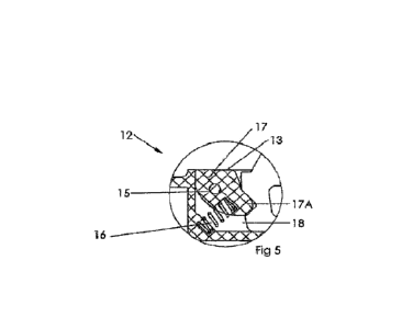
Fig 5 is an expanded view of part of the end of the mount shown in Fig 4,
3
CA 03218797 2023- 11- 10
WO 2022/240301
PCT/NZ2022/050056
Fig 6 is a plan view of the embodiment of the invention shown in Fig 1 with
graphics on
its upper surface,
Figs 7 and 8 are side and end elevations of the embodiment shown in Fig 2,
Fig 9 is a cross-section of the embodiment of the invention shown in Fig 1, in
which the
fin is in a position to be released from the mount,
Fig 10 is an expanded view of the end of the mount shown in Fig 9.
Referring to the drawings a standard fin 1 is releasably secured within a
mount
indicated by arrow 2.
The fin mount is secured within a cavity in a board (not shown) by
conventional means
such as bonding with a suitable resin.
The board of the invention is for water sport use such as a surfboard, a stand-
up
paddle board, a wake board, windsurfing board or a motorised board. The
following
description will focus on surfboards but it will be clear that the embodiments
described
can readily be used for other water sport boards.
The cavity in the board is usually formed when the board is manufactured. Each
manufacturer may provide a different shaped and depth cavity. A common cavity
is
what may be termed a "racetrack shape" with parallel sides and rounded ends.
The
embodiments described in the attached drawings are designed to fit into such a
cavity
and be secured by suitable resins. The invention is not limited to a fin mount
with a
matching racetrack shape or to be used in a cavity of such a shape. Deviations
between the shape of the cavity and the outer shape of the mount can be
accommodated such as by packing and use of more resins. Normally a
manufacturer
will want a shape and size of a mount that is close to that of the cavity to
minimise the
amount of resin required and to ensure that the mount is secured within the
cavity.
At a butt end 3 of the fin 1 (Fig 4), normally the rear end, the fin is
releasably and
rotatably attached to the mount. The various relative positions and directions
in this
specification refer to the mount and fin being viewed as in Figs 1, 2, 4 and 5
with the
butt end at the right- hand end of the drawing and the cam at the distal end
at the left
hand end of the drawing. Anticlockwise or clockwise motion is described with
reference to the same view.
As shown in Figs 4 and 9 a groove 4 is provided in the end 3 of the fin 1 to
engage
releasably and rotatably with a tongue 5 protruding from the rear surface 6 of
the
channel 11 ( Fig 6) in the mount. When the fin 1 is disengaged from the cam as
discussed below it can be manually rotated in a clockwise direction and then
disengaged from the tongue 5 and thus released from the mount and board when
required.
The fin 1 has a series of openings 8 to reduce the weight of the fin while
still retaining
adequate strength to perform its function. The fin 1 is in the locked position
in Fig 4
with its base 9 resting on the floor 10 in the channel 11 (Fig 5) within the
mount 2.
In the drawings, particularly Figs 5 and 10 the cam is generally indicated by
arrow 12,
having an upper surface 13 for application of finger pressure. The cam surface
can be
set substantially within the planar surface of a raised surround 14 of the
channel 11,
when the cam is in position to lock the fin in place. The perimeter of the
surround is of
a streamlined shape so water flows smoothly over the board when in use. A
suitable
4
CA 03218797 2023- 11- 10
WO 2022/240301
PCT/NZ2022/050056
shape is a radiused vertical surface. The rear part of the upper surface 13 of
the cam
is of a size to permit a user to apply finger pressure to it to cause the cam
to rotate
about a pivot point such as a pin 15. The finger pressure is in a downwards
direction
relative to the mount when the device is in the disposition shown in the
drawings.
The cam in this embodiment has a pivoting member 17 integrally formed with a
downwardly depending lug 17A. The lug 17A is shaped to engage with a
complementary shape such as a recess 19 in the distal edge 18 of the fin 1
upon
downward finger pressure being applied to the rear part of the upper surface
13 of the
cam 12. The pivoting member 17 is biased by a steel spring 16 to the locking
position
shown in Figs 4 and 5.
One end of the spring can be fixed within a suitable recess in the pivoting
member 17.
The other end of the spring is fixed to the mount as shown in Figs 5 and 10.
The shape of the lug and recess needs to allow the bottom portion of the
distal end 18
of the fin 1 to smoothly ride over the upper surface of the end of the lug 17A
as the fin
is manually rotated anticlockwise towards its locked position. As the fin
further rotates
the end of the lug 17A moves into correct alignment with the recess 18. The
spring 16
then forces the end of the lug into the recess 18 to securely lock the fin to
the mount.
The shape of the lug 17A and the recess 19 needs to allow the end of the lug
17A to
clear the recess 18 when moving from the locking to the unlocking position to
allow the
end of the fin to be freely rotated clockwise to escape the lug thus allowing
the fin 1 to
be removed from the mount. Sufficient downward finger pressure on the rear
part of
the cam surface 13 forces the pivoting member 17 to rotate in a clockwise
direction
against the force of the spring for lug 17A to move to the unlocking position
shown in
Figs 9 and 10.
The mount of the invention can be manufactured in any desired size. The
dimensions
shown below with reference to Figs 6 to 8 are those of mount for use in a
thicker board.
With a common thinner board the depth dimension "d" is simply reduced while
retaining
the other dimensions as shown below.
The mount can be manufactured from any suitably strong materials such as by
injection moulding using conventional methods.
To exemplify one particular fin mount, the dimensions (mm) of the device shown
in Figs
6 to 8 can be as follows:
a = 7.15, b = 150.0, c = 7.5, d = 5.7, e = 2.2, f = 3.0,0 = 130.0, h = 32.0, i
= R2.0, j =
16.0 and k = 12.5.
These dimensions are given to illustrate suitable dimensions of one device of
the
invention but different devices within the scope of the broad embodiments of
the
invention can and will have different values to those set forth above.
Each of components of the mount and the or each fin are designed so that the
or each
fin remain firmly in place when locked to the mount when secured in the cavity
in the
deck during normal use by a rider.
While this invention has been described with reference to particular
embodiments it is
not to be construed as limited thereto. Furthermore where known equivalents
exist to
specific features or constructional steps such equivalents are included herein
as if
specifically set forth.
5
CA 03218797 2023- 11- 10
WO 2022/240301
PCT/NZ2022/050056
INDUSTRIAL APPLICABILITY
This invention clearly has industrial applicability. Many millions of boards
for use in
watersports are manufactured and sold annually which in use will require
regular fin
replacement.
UTILITY
There is also a specific, credible and substantial use for the invention
permitting a fin to
be replaced on a board without the need for a user to carry an implement to
remove
the fin.
CA 03218797 2023- 11- 10