Note: Descriptions are shown in the official language in which they were submitted.
CA 03218908 2023-10-30
WO 2022/261408
PCT/US2022/032961
1
THREAD FORMING AND THREAD LOCKING FASTENER
BACKGROUND
Technical Field
The present invention relates to threaded fasteners.
Background Information
Conventional threaded fasteners (e.g., screws or bolts) may be designed to
have a self-tapping thread forming action. One example of such a self-tapping
fastener is described in U.S. Patent No. 9,404,524, entitled High Performance
Thread
Rolling Screw/Bolt For Use in An Unthreaded Nut Anchor, by Alan Pritchard, the
contents of which are hereby incorporated by reference.
Other conventional fasteners may include a thread locking mechanism that
may be achieved by, e.g., mechanical interference between the fastener and a
nut
member. An exemplary thread locking fastener is described in U.S. Patent No.
7,722,304, entitled Fastener and Fastener Assembly, by Alan Pritchard, the
contents
is of which are hereby incorporated by reference.
A noted disadvantage of prior art fasteners is that they are optimized for
either
thread forming or thread locking, but not both. This causes users to make
decisions as
to which feature is more important for a particular application, which may
result in
sub-optimal application of such fasteners.
SUMMARY
The disadvantages of the prior art overcome providing an exemplary fastener
that is optimized for both thread forming and thread locking. The fastener
comprises
two separate thread profiles illustratively distributed into three zones along
the shaft
of the fastener. A first zone, which utilizes a thread forming thread profile,
is
immediately adjacent to the entry point of the fastener. Along the first zone
the outer
diameter of the thread profile increases along the first, e.g., 1-5 pitches.
The second
zone transitions from the first zone and utilizes the same thread forming
thread profile
as the first zone but maintains a constant outer thread diameter. The second
zone
extends for, e.g., 1-3 pitches beyond the first zone. The third zone, which
utilizes a
CA 03218908 2023-10-30
WO 2022/261408
PCT/US2022/032961
2
thread locking thread profile, also maintains a constant outer diameter. It
should be
noted that in alternative embodiments, the fastener may only have two zones,
e.g., the
second zone and the third zone. Therefore, it should be noted that a
description of
three zones should be taken as exemplary only.
In accordance with illustrative embodiments of the present invention, the
first
and second thread profiles may be selected to complement each other to achieve
a
desired level of mechanical interference, i.e., thread locking. Further, by
utilizing the
present invention, the second thread profile (thread locking) may be optimized
to
work with the threads created by the first thread profile (thread forming).
This may
io result in an optimized thread locking mechanism. As the fastener forms,
or reforms,
its own threads in the nut member, the amount of variability in tolerances
between the
thread locking thread profile and the nut member's thread profile is reduced.
This
enables a better fit and a more precise locking action than using a
conventional thread
locking thread profile on a pre-formed nut member.
In accordance with illustrative embodiments of the present invention, the
thread locking thread profile may be designed to achieve a locking action by
creation
of mechanical interference at the tips of the thread profile. In alternative
embodiments of the present invention, the thread locking thread profile may be
designed to achieve a locking action by the creation of mechanical
interference along
the flanks of the thread profile, i.e., flank locking. As the fastener forms,
or reforms,
the threads of the nut member, a very close match is possible between the
thread
locking thread profile and the threads of the nut member. By varying the
thread
profile height and width, it is possible to form fasteners that have more or
less locking
action as desired for particular applications.
BRIEF DESCRIPTION OF THE DRAWINGS
The above, and further advantages of embodiments of the present the
invention may be understood in relation to the accompanying drawings in which
like
reference numerals indicate identical or functionally identical elements, of
which:
Fig. 1A is a side view of an exemplary fastener in accordance with an
illustrative embodiment of the present invention;
Fig. 1B is a view of the head of an exemplary fastener viewed along the long
axis in accordance with an illustrative embodiment of the present invention;
CA 03218908 2023-10-30
WO 2022/261408
PCT/US2022/032961
3
Fig. 1C is the view of an exemplary entry point of an exemplary fastener
viewed along the long axis in accordance with an illustrative embodiment of
the
present invention;
Fig. 2 is an enlarged view of the entry point end of an exemplary fastener in
accordance with an illustrative embodiment of the present invention;
Fig. 3 is illustrative views of an exemplary blank for use in forming a
fastener
in accordance with an illustrative embodiment of the present invention;
Fig. 4A is a cross-sectional view of an exemplary thread profile in accordance
with an illustrative embodiment, the present invention;
Fig. 4B is a cross-sectional view of an exemplary thread profile in accordance
with an illustrative embodiment of the present invention;
Fig. 4C is a cross-sectional view of an exemplary thread profile in accordance
with an illustrative embodiment of the present invention;
Fig. 5A is a cross-sectional view illustrating the interference between the
is threads of a nut member and a fastener in accordance with an
illustrative embodiment
of the present invention;
Fig. 5B is a cross-sectional view illustrating the interference between the
threads of a nut member and a fastener in accordance with an illustrative
embodiment
of the present invention;
Fig. 5C is a cross-sectional view illustrating interference between the
threads
of a nut member and a fastener in accordance with an illustrative embodiment
of the
present invention;
Fig. 6 is a cross-sectional view illustrating the insertion of an exemplary
fastener into a threaded nut member in accordance with an illustrative
embodiment of
the present invention;
Fig. 7 is a cross-sectional view illustrating the insertion of a fastener into
a
threaded nut member in accordance with an illustrative embodiment of the
present
invention;
Fig. 8 is a cross-sectional view illustrating the insertion of a fastener into
a
threaded nut member in accordance with an illustrative embodiment of the
present
invention;
Fig. 9 is a cross-sectional view illustrating the insertion of a fastener into
a
threaded nut member in accordance with an illustrative embodiment of the
present
invention;
CA 03218908 2023-10-30
WO 2022/261408
PCT/US2022/032961
4
Fig. 10 is a cross-sectional view illustrating the insertion of fastener into
an
unthreaded nut member in accordance with an illustrative embodiment of the
present
invention;
Fig. 11 is a cross-sectional view illustrating the insertion of a fastener
into an
unthreaded nut member in accordance with an illustrative embodiment of the
present
invention;
Fig. 12 is a cross-sectional view illustrating the insertion of a fastener
into an
unthreaded nut member in accordance with an illustrative embodiment of the
present
invention;
Fig. 13 is a cross-sectional view illustrating the insertion of a fastener
into an
unthreaded nut member in accordance with an illustrative embodiment of the
present
invention;
Fig. 14 is an enlarged view of the entry point end of an exemplary fastener in
accordance with an illustrative embodiment of the present invention;
Fig. 15 is a cross-sectional view illustrating the insertion of an exemplary
fastener into a threaded nut member in accordance with an illustrative
embodiment of
the present invention;
Fig. 16 is a cross-sectional view illustrating the insertion of a fastener
into a
threaded nut member in accordance with an illustrative embodiment of the
present
invention;
Fig. 17 is a cross-sectional view illustrating the insertion of a fastener
into a
threaded nut member in accordance with an illustrative embodiment of the
present
invention;
Fig. 18 is a cross-sectional view illustrating the insertion of a fastener
into a
threaded nut member in accordance with an illustrative embodiment of the
present
invention;
Fig. 19 is a cross-sectional view illustrating the insertion of fastener into
an
unthreaded nut member in accordance with an illustrative embodiment of the
present
invention;
Fig. 20 is a cross-sectional view illustrating the insertion of a fastener
into an
unthreaded nut member in accordance with an illustrative embodiment of the
present
invention;
CA 03218908 2023-10-30
WO 2022/261408
PCT/US2022/032961
Fig. 21 is a cross-sectional view illustrating the insertion of a fastener
into an
unthreaded nut member in accordance with an illustrative embodiment of the
present
invention; and
Fig. 22 is a cross-sectional view illustrating the insertion of a fastener
into an
5 unthreaded nut member in accordance with an illustrative embodiment of
the present
invention;
Fig. 23A is a cross sectional view illustrating a maximum condition for a nut
member in accordance with an illustrative embodiment of the present invention;
Fig. 23B is a cross sectional view illustrating a minimum condition for a nut
member in accordance with an illustrative embodiment of the present invention;
Fig. 24A is a cross sectional view illustrating a maximum condition for a nut
member in accordance with an illustrative embodiment of the present invention;
Fig. 24B is a cross sectional view illustrating a minimum condition for a nut
member in accordance with an illustrative embodiment of the present invention;
Fig. 25 is a cross-sectional view of an illustrative thread locking fastener
illustrating variability of the amount of locking in accordance with an
illustrative
embodiment of the present invention; and
Fig. 26 is a cross-sectional view of an illustrative flank locking fastener
illustrating variability of the amount of locking in accordance with an
illustrative
embodiment of the present invention.
DETAILED DESCRIPTION OF AN ILLUSTRATIVE
EMBODIMENT
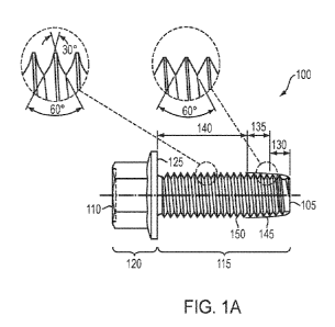
Fig. 1A is a cross-sectional view of an exemplary thread forming and thread
locking fastener 100 in accordance with an illustrative embodiment of the
present
invention. The fastener 100 includes an entry point 105 and a head 110 with a
shaft
115 extending therebetween. Illustratively, entry point 105 is illustrated as
having a
substantially flat end. However, it should be noted that in alternative
embodiments of
the present invention, the fastener 100 may have an entry point 105 that is
rounded,
pointed, etc. As such, the description of entry point 105 being substantially
flat should
be taken as exemplary only. Head 110 is illustratively shown as having a
hexagonal
CA 03218908 2023-10-30
WO 2022/261408
PCT/US2022/032961
6
shape for use with a driving apparatus for insertion. Head 110 extends for
some length
120 in the same axis of the shaft 115 to enable a driver, e.g., a wrench, etc.
to engage
the head 110 to exert torque on the fastener for insertion of the fastener
into a nut
member (not shown). Head 110 includes a substantially flat bottom 125 that is
designed to rest flush with a nut member (not shown) when the fastener is
fully
inserted. As will be appreciated by those skilled in the art, head 110 may
have a
plurality of differing shapes based on the desired driving apparatus.
Therefore, the
description of head 110 having a hexagonal shape should be taken as exemplary
only.
The body or shaft 115 of the fastener 100 includes a plurality of zones of
threads including, for example, a first zone 130, a second zone 135, and a
third zone
140. Illustratively, the three zones are utilized to both perform a thread
forming
function as well as a thread locking function once the fastener has been
inserted into a
nut member. The first zone 130 is illustratively approximately 1-5 pitches
long of an
exemplary first thread profile angling outward from the core with an
increasing
is diameter as the zone moves away from the entry point 105 of the
fastener. That is, the
outer diameter of the first zone 130 is smallest at entry point 105 and
enlarges as the
threads move towards head 110 along the shaft 115. The second zone 135
illustratively comprises an additional 1-3 pitches of the first (thread
forming) thread
profile but with a substantially constant outer diameter. As is illustrated in
Fig. 1A,
the first thread profile illustratively comprises a substantially 60 angled
thread profile
cross section. In exemplary embodiments, the first thread profile may comprise
that
described in the above-incorporated U.S. Patent No. 9,404,524. It should be
noted that
while a particular thread forming thread profile is shown and described, the
principles
of the present invention may utilize any thread forming thread profile in
alternative
embodiments of the present invention. Therefore, the particular thread forming
thread
profile shown and described herein should be taken as exemplary only.
The third zone 140 utilizes a second thread profile, which is illustratively a
thread locking thread profile. As is illustrated in Fig. 1A, the exemplary
second thread
profile comprises a 60 angled thread at the base of the thread that
transitions to a 30
3 0 angled thread at the tip. An exemplary thread locking thread profile is
described in the
above-incorporated U.S. Patent No. 7,722,304. It should be noted that while a
particular thread locking profile is shown and described, the principles of
the present
invention may utilize any thread locking thread profile in alternative
embodiments of
CA 03218908 2023-10-30
WO 2022/261408
PCT/US2022/032961
7
the present invention. Therefore, the particular thread locking thread profile
shown
and described herein should be taken as exemplary only.
Thus, in operation, when a fastener 100 in accordance with an illustrative
embodiment of the present invention is inserted into a nut member, the threads
of the
first zone engage the nut member as the fastener is initially inserted. The
first and
second zone threads deform the nut member to create threads. Upon continued
insertion of the fastener into the nut member, the threads of the third zone
engage the
newly created threads to induce mechanical interference, which causes a
locking
mechanism to occur. Illustratively, the second thread profile is chosen to
compliment
the first thread profile. In accordance with alternative embodiments of the
present
invention, the two thread profiles may be selected so that the thread locking
profile
(the second thread profile) is designed with the a priori knowledge of the
dimensions
of the threads created in a nut member by the thread forming profile (the
first thread
profile). As the fastener is creating the internal threads in an unthreaded
nut member,
is the thread locking profile threads may be configured for optimized
performance with
the internal threads. Examples of variations are described below in relation
to Figs.
4A, B, C and 5A, B, C.
Further, in accordance with illustrative embodiments of the present invention,
the thread forming and thread locking thread profiles may be designed to
create a
specified amount of thread locking. This may be desirous for a number of
reasons.
For example, a particular user of the fastener may desire that the fastener
may be able
to be removed and reinserted into the nut member a specified number of times,
e.g., at
least 10, while maintaining at least a minimum prevailing torque. In such a
scenario,
a fastener with reduced locking action may be desirous. Conversely, a fastener
for
.. use in an apparatus where there is a need for a high prevailing torque may
be designed
to have a higher locking action. Exemplary techniques for varying the amount
of
thread locking are shown and described below in relation to Figs. 25-26.
Fig. 1B is an exemplary view of the head 110 of the fastener 100 viewed along
the long axis of the fastener in accordance with an illustrative embodiment of
the
.. present invention. As noted above, the illustration and description of
exemplary head
having a hexagonal shape should be taken as exemplary only. Fig. 1C is a view
of the
fastener 100 from the entry point 105 along the long axis of the fastener in
accordance
with an illustrative embodiment of the present invention. As can be
appreciated from
Fig. 1C, the shaft 115 of the fastener is illustratively shaped having a
plurality, e.g.,
CA 03218908 2023-10-30
WO 2022/261408
PCT/US2022/032961
8
three lobes, in cross section. It should be noted that the use of a multi-
lobed shaft is
exemplary only and the principles of the present invention may be utilized
with
fasteners having shafts that are substantially circular. As will be
appreciated by those
skilled in the art, various types of fastener shaft cross sections may be
utilized to
achieve desired properties of the fastener. More particularly, it is expressly
contemplated that shafts having more than three lobes may be utilized in
accordance
with alternative embodiments of the present invention. Further, in alternative
embodiments, the shaft may have a varying cross section. For example, the
shaft may
have a substantially circular cross-sectional area close to the entry point,
but transition
to a non-circular cross-sectional area along the length of the shaft. An
exemplary
non-circular cross-sectional area would be, e.g., a three-lobed cross-
sectional area.
However, it is expressly contemplated that other forms on substantially non-
circular
cross-sectional areas may be utilized in accordance with alternative
embodiments of
the present invention. The principles of the present invention may be utilized
with a
is wide range of fastener shaft 115 cross sectional shapes in order to
achieve desired
functionality.
Fig. 2 is an enlarged view of the entry point end of a fastener 100 in
accordance with an illustrative embodiment of the present invention. As can be
seen
from Fig. 2, the first zone 130 increases in outer diameter as it moves from
the entry
point 105. The first zone utilizes a first thread profile, which is
illustratively a thread
forming thread profile. The second zone 135 continues the use of the thread
forming
threads, but at an overall diameter that is substantially constant, unlike the
first zone
130 which has an increasing overall thread diameter. The third zone 140 then
utilizes
a second thread profile, e.g., a thread locking thread profile, for the
remainder of the
fastener 100.
Fig. 3 is an exemplary view of a headed blank 300 for use in forming a
fastener 100 in accordance with an illustrative embodiment of the present
invention.
Illustratively, the blank 300 comprises a single diameter blank, which eases
manufacturing difficulty. However, it is expressly contemplated that the
principles of
3 0 the present invention may be utilized with more sophisticated blanks.
Figs. 4A, B, C illustrate illustrative thread profiles that may be utilized in
alternative embodiments of the present invention. It should be noted that each
thread
profile has the same cross-sectional area. Fig. 4A is representative of an
illustrative
600 thread profile, such as that shown in Fig. 1. Fig. 4B is representative of
an
CA 03218908 2023-10-30
WO 2022/261408
PCT/US2022/032961
9
exemplary radius thread profile. Fig. 4C is representative of an exemplary
angular
thread form with a 60V30 thread profile. It should be noted that in
alternative
embodiments of the present invention, differing thread profiles may be
utilized.
Therefore, it is expressly contemplated that the thread profiles shown in
Figs. 4A, B,
C are exemplary only.
Figs. 5A, B, C illustrate exemplary ranges of potential mechanical
interference
that may be obtained by utilizing differing thread profiles for nut members
and
fasteners in accordance with exemplary design choices in accordance with
illustrative
embodiments of the present invention. The various figures show combinations of
thread profiles described above in relation to Figs. 4A,B, C. As can be seen
from Figs.
5A, B, and C, by varying the internal and external thread profiles, varying
degrees of
mechanical interference can be achieved. In alternative embodiments, by
selecting
various combination of thread profiles, a desired amount of mechanical
interference
may be achieved.
Fig. 6 is a cross-sectional view 600 of the insertion of a fastener 100 into a
threaded nut member 605 in accordance with an illustrative embodiment of the
present invention. The threaded nut member 605 illustratively includes a set
of
preformed threads 610. View 600 is of the fastener 100 and nut 605 immediately
prior
to insertion of the end 105 of the fastener 100 into the threaded nut member
605. The
.. view along section A-A illustrates an exemplary cross section 615 of
fastener 100 and
the threaded nut member.
Fig. 7 is a cross-sectional view 700 of the insertion of a fastener 100 into a
threaded nut member 605 in accordance with an illustrative embodiment of the
present invention. In view 700, the first 130 and second 135 zones of the
fastener 100
have been inserted into the threaded nut member 605. As can be seen in the
enlarged
view, space is left between the first 130 and second zone 135 threads and the
internal
threads 610 of the threaded nut member 605.
Fig. 8 is a cross-sectional view 800 of the insertion of a fastener 100 into
an
unthreaded nut member in accordance with an illustrative embodiment of the
present
invention. In view 800, the first zone threads 130 have nearly passed through
the
threaded nut member 605, while the second zone threads 135 are completely
contained within the nut member 605. As can be seen, the third zone threads
140 have
generated tip penetration at points 805 within the nut member.
CA 03218908 2023-10-30
WO 2022/261408
PCT/US2022/032961
Fig. 9 is a cross-sectional view 900 of the insertion of a fastener 100 into a
threaded nut member 605 in accordance with an illustrative embodiment of the
present invention. In view 900, the first 130 and second zone threads 135 have
passed
completely through the nut member 605 and for each internal thread 605, there
are tip
5 penetration points 905 of the third zone threads 140. With the faster 100
inserted as
shown in Fig. 9, the points of tip penetration 905 generate a mechanical
locking
mechanism, thereby working to secure the fastener in the threaded nut member.
In an illustrative embodiment of the present invention, the thread forming
thread profile of the first and second zone threads are designed so as to
slightly
10 .. enlarge the diameter of the threads of the threaded nut member. This
resizing enables
the fastener to be constructed so that there is an optimized interference
between the
resized threads and the thread locking threads of the third zone threads. By
selecting
the thread profile and size for the first and second zone threads, the desired
amount of
mechanical interference with the third zone threads may be achieved. However,
it
is should be noted that in alternative embodiments of the present
invention, the
preformed internal threads are not enlarged by the first and second zone
threads.
Therefore, the description of the internal threads being enlarged should be
taken as
exemplary only. Further, the action of the thread forming thread profile
reduces or
eliminates debris from the formation of the threads. This reduces waste and is
critical
in certain operational environments.
Fig. 10 is a cross-sectional view 1000 of the insertion of a fastener 100 into
an
un-threaded nut member 1005 in accordance with an illustrative embodiment of
the
present invention. In view 1000, the fastener 100 is that about to be inserted
into a nut
member 1005, which has an un-threaded aperture or hole 1010.
Fig. 11 is a cross-sectional view 1100 of the insertion of a fastener 100 into
an
unthreaded nut member 1005 in accordance with an illustrative embodiment of
the
present invention. View 1100 shows when the first and second zone threads have
been
inserted into the unthreaded nut member completely.
Fig. 12 is a cross-sectional view 1200 of the insertion of a fastener 100 into
an
unthreaded nut member 1005 in accordance with an illustrative embodiment of
the
present invention. The third zone threads 140 have now entered the previously
formed
threads and have generated tip penetrations at points 1205.
CA 03218908 2023-10-30
WO 2022/261408
PCT/US2022/032961
11
Fig. 13 is a cross-sectional view 1300 of the insertion of a fastener 100 into
an
unthreaded nut member in accordance with an illustrative embodiment of the
present
invention. In view 1300, the first and third zone threads have passed through
the nut
member 1005, a plurality of third zone threads are engaging the nut member
1005 at a
plurality of tip penetration points 1305.
As noted above, in relation to Figs. 6-9, in illustrative embodiments of the
present invention, the first and second zone threads may be sized to create an
optimally sized thread to achieve a desired mechanical interference with the
third
zone threads.
it) The thread locking action described above utilizes mechanical
interference at
the tips of the third zone thread profile to create a locking action. These
embodiments
work well in nut members made from steel or other hard metals. However, in
softer
materials, such as aluminum, or soft cast alloys, the desired outcome may not
be
achieved. In another embodiment of the present invention, the novel fastener
is
is designed to create a locking action by the use of mechanical
interference along the
flanks of the thread. This flank locking action has been found to work well
with
materials where the previously described tip locking action does not.
Fig. 14 is an enlarged view of the entry point end of an exemplary fastener in
accordance with an illustrative embodiment of the present invention. Fig. 14,
similar
20 to Fig. 2 described above, illustrates a first zone 130, a second zone
135, and a third
zone 140. The first zone illustratively utilizes a thread forming thread
profile that is
designed to form a flank locking thread in the nut member (not shown). The
second
and third zones illustratively utilize a thread locking thread profile that is
designed to
induce flank locking mechanical interference with the threads formed by the
thread
25 forming thread profile.
In alternative embodiments of the present invention, the first zone 130 may
not be utilized. In such alternative embodiments, the fastener comprises the
second
zone 135 (thread forming thread profile) and third zone 140 (thread locking
thread
profile).
30 Figs. 15-22 are similar to Figs. 6-13 but illustrate the insertion of a
fastener
that utilizes a thread forming thread profile and a thread locking thread
profile that
causes flank locking mechanical interference.
CA 03218908 2023-10-30
WO 2022/261408
PCT/US2022/032961
12
Fig. 15 is a cross-sectional view 1500 of the insertion of a fastener 100 into
a
threaded nut member 1505 in accordance with an illustrative embodiment of the
present invention. The threaded nut member 1505 illustratively includes a set
of
preformed threads 1510. View 1500 is of the fastener 100 and nut member 1505
immediately prior to insertion of the end 105 of the fastener 100 into the
threaded nut
member 1505. The view along section A-A illustrates an exemplary cross section
1515 of fastener 100 and the threaded nut member.
Fig. 16 is a cross-sectional view 1600 of the insertion of a fastener 100 into
a
threaded nut member 1505 in accordance with an illustrative embodiment of the
present invention. In view 1600, the first 130 and second 135 zones of the
fastener
100 have been inserted into the threaded nut member 1505. As can be seen in
the
enlarged view, space is left between the first 130 and second zone 135 threads
and the
internal threads 1510 of the threaded nut member 1505.
Fig. 17 is a cross-sectional view 1700 of the insertion of a fastener 100 into
an
is unthreaded nut member in accordance with an illustrative embodiment of
the present
invention. In view 800, the first zone threads 130 have nearly passed through
the
threaded nut member 1505, while the second zone threads 135 are completely
contained within the nut member 1505. As can be seen, the third zone threads
140
have generated mechanical interference along the flanks of the threads at
points 1705
within the nut member.
Fig. 18 is a cross-sectional view 1800 of the insertion of a fastener 100 into
a
threaded nut member 1505 in accordance with an illustrative embodiment of the
present invention. In view 1800, the first 130 and second zone threads 135
have
passed completely through the nut member 1505 and for each internal thread
1510,
there are flank mechanical interference points 1705 with each of the third
zone
threads 140. With the faster 100 inserted as shown in Fig. 18, the flank
locking
mechanical interference points 1705 generate a mechanical locking mechanism,
thereby working to secure the fastener in the threaded nut member.
In an illustrative embodiment of the present invention, the thread forming
3 0 thread profile of the first and second zone threads are designed so as
to slightly
enlarge the diameter of the threads of the threaded nut member. This resizing
enables
the fastener to be constructed so that there is an optimized interference
between the
resized threads and the thread locking threads of the third zone threads. By
selecting
the thread profile and size for the first and second zone threads, the desired
amount of
CA 03218908 2023-10-30
WO 2022/261408
PCT/US2022/032961
13
mechanical interference with the third zone threads may be achieved. However,
it
should be noted that in alternative embodiments of the present invention, the
preformed internal threads are not enlarged by the first and second zone
threads.
Therefore, the description of the internal threads being enlarged should be
taken as
exemplary only.
Fig. 19 is a cross-sectional view 1900 of the insertion of a fastener 100 into
an
un-threaded nut member 100 in accordance with an illustrative embodiment of
the
present invention. In view 1900, the fastener 100 is that about to be inserted
into a nut
member 1005, which has an un-threaded aperture or hole 1010.
Fig. 20 is a cross-sectional view 1100 of the insertion of a fastener 100 into
an
unthreaded nut member 2005 in accordance with an illustrative embodiment of
the
present invention. View 1100 shows when the first 130 and second zone 135
threads
have been inserted into the unthreaded nut member completely. The thread
forming
thread profile of the second zone 135 has begun to form the unthreaded nut
member
is 1005 to create internal threads within the inside of the aperture 1010.
Fig. 21 is a cross-sectional view 1200 of the insertion of a fastener 100 into
an
unthreaded nut member 2005 in accordance with an illustrative embodiment of
the
present invention. The third zone threads 140 have now entered the previously
formed
threads and have generated flank locking mechanical interference at points
2105.
Fig. 22 is a cross-sectional view 2200 of the insertion of a fastener 100 into
an
unthreaded nut member 2005 in accordance with an illustrative embodiment of
the
present invention. In view 2200, the first 130 and second 135 zone threads
have
passed through the nut member 1005, a plurality of third zone threads are
engaging
the nut member 1005 at a plurality of flank locking mechanical interference
points
2105.
Fig. 23A is a cross sectional view 2300A illustrating a maximum condition for
a nut member in accordance with an illustrative embodiment of the present
invention.
Fig. 23B is a cross sectional view 2300B illustrating a minimum condition for
a nut member in accordance with an illustrative embodiment of the present
invention.
Fig. 24A is a cross sectional view 2400A illustrating a maximum condition for
a nut member in accordance with an illustrative embodiment of the present
invention.
Fig. 24B is a cross sectional view 2400B illustrating a minimum condition for
a nut member in accordance with an illustrative embodiment of the present
invention.
CA 03218908 2023-10-30
WO 2022/261408
PCT/US2022/032961
14
Fig. 25 is a cross-sectional view 2500 of an illustrative thread locking
fastener
illustrating variability of the amount of locking in accordance with an
illustrative
embodiment of the present invention. Exemplary view 2500 is of a fastener 100
that
utilizes a thread forming thread profile that is designed to create mechanical
interferences at the tips, such as that shown and described above in relation
to Figs. 6-
13. In view 2500 X represents a length of an individual thread of the thread
locking
thread profile and Y represents a height of a thread of the thread locking
thread
profile. In order to generate a fastener with more locking action, X is
increased, and
Y is decreased. Conversely, to reduce the amount of locking action generated
by a
particular fastener, X is reduced, and Y is increased.
Fig. 26 is a cross-sectional view of an illustrative flank locking fastener
illustrating variability of the amount of locking in accordance with an
illustrative
embodiment of the present invention. Exemplary view 2600 is of a fastener 100
that
utilizes a thread forming thread profile that is designed to create mechanical
is interferences at the flanks of the threads, such as that shown and
described above in
relation to Figs. 14-22. In view 2600, X represents a length of an individual
thread of
the thread locking thread profile and Y represents a height of a thread of the
thread
locking thread profile. In order to generate a fastener with more locking
action, X is
decreased, and Y is increased. Conversely, to reduce the amount of locking
action
generated by a particular fastener, X is increased, and Y is decreased.
In this manner, a fastener may be designed to generate an amount of locking
action that is desired for a particular application. The amount of locking
action
(prevailing torque) may also be maintained through a plurality of insertions
and
removals. As a fastener of the present invention produces little or no debris
from the
thread forming action, the nut member may remain suitable for additional
insertions
of the fastener.
It should be noted that while the present invention has been described in
relation to particular thread profiles, the principles of the present
invention may be
utilized with a variety of thread forming and/or thread locking thread
profiles. As
3 0 such, the specific descriptions of particular thread profiles contained
herein should be
viewed as exemplary only. Furthermore, while various descriptions of number of
pitch threads in the various zones has been given, as will be appreciated by
those
skilled in the art, the number of pitches in the various zones may vary
depending on
CA 03218908 2023-10-30
WO 2022/261408
PCT/US2022/032961
intended uses. As such, the description of particular numbers of pitches in
the various
zones should be taken as exemplary.
The present description is written in terms of various illustrative
embodiments
of the present invention. As will be appreciated by those skilled in the art,
various
5 modifications may be made to the embodiments described herein without
departing
from the spirit or scope of the invention. As such, the described embodiments
should
be taken as illustrative only.
What is claimed is: