Note: Descriptions are shown in the official language in which they were submitted.
BULKHEAD ADAPTER ASSEMBLY HAVING INTEGRALLY MOLDED BODY AND
METHOD FORMING SAME
Background
[0001] This disclosure relates to an adapter assembly, and particularly a
modified
adapter (also referred to as a bulkhead adapter assembly or bulkhead adapter)
that
connects outside and internal cables. This bulkhead adapter disclosure finds
particular application in connecting optical fibers that are received in
opposite ends
of the adapter without a significant loss in transmission that are typically
used in
the telecommunications industry.
[0002] It is known to provide a housing or enclosure where multiple optical
fibers
from a fiber optic cable are segregated from one another, and also segregated
from
a remainder of the cable assembly. The segregated fibers are used to connect
with
a drop cable in the fiber optic network industry. Preferably, the drop cable
has a
pre-connectorized end that is configured for a snap-fit, plug-in connection
with one
end of the bulkhead adapter assembly, and more particularly with the body of
the
bulkhead adapter assembly. An opposite face or end of the body of the bulkhead
adapter assembly is similarly configured to receive an end of a connector
provided
on the end of the segregated optical fiber located in the enclosure housing.
In this
manner, the individual components properly interconnect with one another.
[0003] Bulkhead adapter assembly's that achieve these general objectives
are
known in the industry. Is, however, desire to reduce the number of components
or individual components used in the bulkhead adapter assembly in order to
reduce
cost. Further, a smaller number of components leads to reduced inventory,
simpler
assembly, and reduces tolerance stack-up issues. A reduced number of
Date Recue/Date Received 2023-11-07
components also, in turn, reduces the number of potential leak paths in the
assembly.
[0004] Consequently, a need exists for an improved arrangement that
addresses
one or more of the issues noted above, and provides at least one or more of
the
above-described features, as well as still other features and benefits when
compared to other, known bulkhead adapter assemblies.
Summary
[0005] A new and improved bulkhead adapter assembly is provided.
[0006] The bulkhead adapter assembly (and method of forming same) is
configured
at a first end to receive an associated optical fiber connector housing a
terminal end of
an associated fiber. The adapter assembly is joined to an associated closure
at a second
end. The bulkhead adapter assembly includes a holder having first and second
flexible
arms extending axially outwardly from a first end of the holder along a first
axis. The first
end of the holder includes an opening dimensioned to receive the associated
optical fiber
therein. A shoulder is formed at a terminal end of each of the flexible arms
wherein each
shoulder has an undercut extending perpendicularly to the first axis that is
configured to
operatively engage the associated optical fiber connector. A central portion
of the holder
has a recess extending inwardly from a second end of the holder, with an
opening that
receives the associated optical fiber therethrough. A sleeve is dimensioned
for axial
receipt in the holder recess dimensioned to receive the associated optical
fiber therein,
the sleeve aligning the associated optical fiber within the bulkhead adapter
assembly. A
hollow body has a recess that receives the holder and sleeve in a first end of
the body,
the body including an externally threaded first region and an internally
threaded second
region. A nut has an internally threaded region that engages the externally
threaded first
region of the hollow body and having an internal shoulder. A base member has
an
externally threaded region that threadedly interconnects with the internally
threaded
second region of the body.
[0007] The sleeve in one variation may be a ceramic material.
2
Date Recue/Date Received 2023-11-07
[0008] The adapter assembly may include a first seal member interposed
between the nut and body, and a second seal member interposed between the
body and base member to seal around the associated optical fiber connector.
[0009] Each of the flexible arms may include a tapered surface adjacent a
terminal end thereof configured to abuttingly engage the associated optical
fiber
connector such that the arms diverge away from each other as the associated
optical fiber connector is advanced relative to the flexible arms.
[0010] Each of the flexible arms may include a tapered surface adjacent a
terminal end thereof configured to abuttingly engage the associated optical
fiber
connector such that the arms diverge away from each other as the associated
optical fiber connector is advanced relative to the flexible arms.
[0011] The central portion of the holder may be located axially inward from
terminal ends of the first and second flexible arms such that the flexible
arms
extend over a greater axial extent of the associated optical fiber connector
when
received in the holder recess.
[0012] The nut includes one or more indentations/notches configured to
receive
a mating, specially configured associated tool to rotate the nut onto the body
and
retain the holder and sleeve in the body.
[0013] A method of assembling a bulkhead adapter assembly configured at a
first
end to receive an associated optical fiber connector housing a terminal end of
an
associated fiber, and joined to an associated closure at a second end,
includes
providing an elongated holder having at least first and second flexible arms
extending axially outwardly from a first end of the holder along a first axis.
Providing the first end of the holder may include providing an opening
dimensioned
to receive the associated optical fiber therein, a shoulder formed at a
terminal end
3
Date Recue/Date Received 2023-11-07
of each of the flexible ends wherein each shoulder has an undercut extending
perpendicularly to the first axis that is configured to operatively engage the
associated optical fiber connector, a central portion of the holder including
a recess
extending inwardly from a second end of the holder, and an opening through the
central portion that receives the associated optical fiber therethrough.
[0014] The method may include receiving a sleeve in the holder recess
dimensioned wherein the sleeve is dimensioned to receive the associated
optical
fiber therein.
[0015] The method may include using the sleeve to align the associated
optical
fiber within the bulkhead adapter assembly.
[0016] The method may include providing a hollow body having a recess and
receiving the holder and sleeve in a first end of the body, the body including
an
externally threaded first region and an internally threaded second region.
[0017] The method may include threadedly engaging a nut having an
internally
threaded region with the externally threaded first region of the hollow body,
and
threadedly engaging a base member having an externally threaded region with
the
internally threaded second region of the body.
[0018] The method may include forming the sleeve of a ceramic material.
[0019] The method may include interposing a first seal member between the nut
and body, and interposing a second seal interposed between the body and base
member to seal around the associated optical fiber connector.
[0020] The method may include providing a tapered surface adjacent a terminal
end of each flexible arm to abuttingly engage the associated optical fiber
connector
4
Date Recue/Date Received 2023-11-07
such that the arms diverge away from each other as the associated optical
fiber
connector is advanced relative to the flexible arms.
[0021] The method may include locating the central portion of the holder
axially
inward from terminal ends of the first and second flexible arms such that the
flexible arms extend over a greater axial extent of the associated optical
fiber
connector when received in the holder recess.The method of claim 8 further
comprising providing one or more indentations/notches in the nut configured to
receive a mating, specially configured associated tool to rotate the nut onto
the
body and retain the holder and sleeve in the body.
[0022] The new assembly reduces the number of components or individual
components used in the bulkhead adapter assembly, thereby reducing costs.
[0023] A smaller number of components results in reduced inventory issues.
[0024] Further, the overall assembly is easy to assemble.
[0025] Tolerance stack-up issues are addressed since a lesser number of
components are used and thus the overall number of tolerances between
assembled components is reduced.
[0026] There are also fewer potential leak paths in the assembly as a
result of
using fewer components.
[0027] Still other benefits and advantages of the present disclosure will
become
more apparent from reading and understanding the following detailed
description.
Brief Description of the Drawings
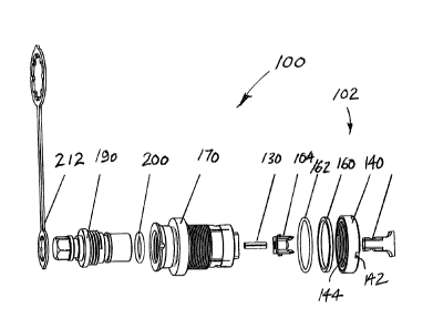
[0028] Figure 1 is an exploded, perspective view of a preferred bulkhead
adapter
assembly that particularly illustrates the individual components prior to
assembly.
Date Recue/Date Received 2023-11-07
[0029] Figure 2 is an enlarged elevational view of a holder component of
the
bulkhead adapter assembly of Figure 1.
[0030] Figure 3 is an enlarged, longitudinal cross-sectional view of the
holder of
Figure 2.
[0031] Figure 4 is an enlarged end view of an internally threaded nut
component
of the bulkhead adapter assembly of Figure 1.
[0032] Figure 5 is an enlarged, longitudinal view of a body of the bulkhead
adapter assembly of Figure 1 with selected portions thereof shown in
elevation.
[0033] Figure 6 is an enlarged, longitudinal cross-sectional view of a dust
cap
received over a first end of the bulkhead adapter assembly of Figure 1.
[0034] Figure 7 is an enlarged, longitudinal cross-sectional view of a dust
cap
received at a second end of the bulkhead adapter assembly of Figure 1.
[0035] Figure 8 includes Figure 8A which is an exploded, perspective view
of a
prior art bulkhead adapter assembly that particularly illustrates the
individual
components thereof prior to assembly, and Figure 8B which is an enlarged,
exploded view of the shroud subassembly of Figure 8A.
Detailed Description
[0036] The following description with reference to the accompanying drawings
is provided to assist in a comprehensive understanding of one or more
embodiments of the present disclosure as defined by the claims and their
equivalents. It includes various specific details to assist in that
understanding but
these are to be regarded as merely exemplary. Accordingly, those of ordinary
skill
in the art will recognize that various changes and modifications of the
various
embodiments described herein can be made without departing from the scope and
6
Date Recue/Date Received 2023-11-07
spirit of the present disclosure. Various exemplary embodiments of the present
disclosure are not limited to the specific details of different embodiments
and
should be construed as including all changes and/or equivalents or substitutes
included in the ideas and technological scope of the appended claims. In
describing
the drawings, where possible similar reference numerals are used for similar
elements.
[0037] The terms "include" or "may include" used in the present disclosure
indicate the presence of disclosed corresponding functions, operations,
elements,
and the like, and do not limit additional one or more functions, operations,
elements, and the like. In addition, it should be understood that the terms
"include", "including", "have" or "having" used in the present disclosure are
to
indicate the presence of components, features, numbers, steps, operations,
elements, parts, or a combination thereof described in the specification, and
do not
preclude the presence or addition of one or more other features, numbers,
steps,
operations, elements, parts, or a combination thereof.
[0038] The terms "or" or "at least one of A or/and B" used in the present
disclosure include any and all combinations of words enumerated with them. For
example, "A or B" or "at least one of A or/and B" mean including A, including
B, or
including both A and B.
[0039] Although the terms such as "first" and "second" used in the present
disclosure may modify various elements of the different exemplary embodiments,
these terms do not limit the corresponding elements. For example, these terms
do
not limit an order and/or importance of the corresponding elements, nor do
these
terms preclude additional elements (e.g., second, third, etc.) The terms may
be
used to distinguish one element from another element. For example, a first
7
Date Recue/Date Received 2023-11-07
mechanical device and a second mechanical device all indicate mechanical
devices
and may indicate different types of mechanical devices or the same type of
mechanical device. For example, a first element may be named a second element
without departing from the scope of the various exemplary embodiments of the
present disclosure, and similarly, a second element may be named a first
element.
[0040]
It will be understood that, when an element is mentioned as being
"connected" or "coupled" to another element, the element may be directly
connected or coupled to another element, and there may be an intervening
element between the element and another element. To the contrary, it will be
understood that, when an element is mentioned as being "directly connected" or
"directly coupled" to another element, there is no intervening element between
the element and another element.
[0041] The terms used in the various exemplary embodiments of the present
disclosure are for the purpose of describing specific exemplary embodiments
only
and are not intended to limit various exemplary embodiments of the present
disclosure. As used herein, the singular forms are intended to include the
plural
forms as well, unless the context clearly indicates otherwise. Use of
dimensions,
temperatures, ranges, time, relationships (e.g., "perpendicular", "parallel"),
etc.
that either use or do not use further adjectives such as "generally",
"substantially",
"about" or "approximately" in the description or claims are intended to cover
both
the specific dimension, temperature, range, time, relationship, etc., as well
as a
range of equivalents (function, way, or result) and only intended to be
limited by
teachings of the prior art.
[0042] The terms used in the various exemplary embodiments of the present
disclosure are for the purpose of describing specific exemplary embodiments
only
8
Date Recue/Date Received 2023-11-07
and are not intended to limit various exemplary embodiments of the present
disclosure. As used herein, the singular forms are intended to include the
plural
forms as well, unless the context clearly indicates otherwise.
[0043] All of the terms used herein including technical or scientific terms
have
the same meanings as those generally understood by an ordinary skilled person
in
the related art unless they are defined otherwise. The terms defined in a
generally
used dictionary should be interpreted as having the same meanings as the
contextual meanings of the relevant technology and should not be interpreted
as
having inconsistent or exaggerated meanings unless they are clearly defined in
the
various exemplary embodiments.
[0044] Turning to Figure 1, and also Figures 2 ¨ 7, there is shown a
bulkhead
adapter or bulkhead adapter assembly 100. The adapter 100 receives one end of
a first fiber optic cable (not shown), and particularly an exposed optical
fiber
thereof, that leads from, for example, an enclosure or housing (not shown).
The
fiber optic cable includes a connector (not shown) configured for receipt in a
first
or right-hand end 102 of the adapter 100 as oriented in Figure 1. The fiber
optic
cable connector is dimensioned for receipt in the adapter 100 where the
exposed
optical fiber is inserted into a holder 104. A first end 106 of the holder 104
includes
an opening 108 (Figure 3) dimensioned to receive the optical fiber therein.
The
holder 104 also preferably includes two or more flexible arms 110 that have an
elongated conformation and extend axially in cantilevered fashion from second
end
112 of the holder. Each arm 110 preferably includes a shoulder 114 at the
first end
106 with an undercut 116 extending substantially perpendicular to longitudinal
direction of the arm for snap-fit connection. That is, the optical fiber
connector
(not shown) is advanced toward the holder 104, the tapered surface 118
abuttingly
9
Date Recue/Date Received 2023-11-07
engages the optical fiber connector, the arms 110 diverge outwardly
(substantially
perpendicular to the longitudinal axis of the holder) as the tapered surfaces
ride
over the optical fiber connector to receive at least a portion of the
connector in a
cavity 120 between a central portion 122 of the holder and the arms, and then
the
undercuts 116 move inwardly (i.e., snap-fit) and secure the optical fiber
connector
to the holder. The optical fiber is received through the opening 108 for
receipt in
one end of a ceramic sleeve 130 (Figure 1). The ceramic sleeve 130 serves to
align
the end of the optical fiber from the housing/enclosure (from the right-hand
end
of Figure 1) with a similar optical fiber extending from a drop cable
(extending from
the left-hand end of Figure 1 - not shown). The ceramic sleeve 130 is
dimensioned
for receipt in recess 132 of the holder 104, where the recess extends axially
inward
from the second end 112 and is in communication with the opening 108 adjacent
the first end 106 of the holder.
[0045] With continued reference to Figure 1, and additional reference to
Figure
4, an internally threaded member or jam nut 140 is shown. A first or outer end
of
the nut 140 includes one or more indentations or notches 142 that are
dimensioned to receive a specially configured tool (not shown) having a like
number of circumferentially spaced tabs. The tabs of the tool engage the
notches
142 and facilitate tightening and/or loosening the nut 140. The nut 140 is
internally
threaded 144 (Figure 1) and also includes a circumferentially continuous
shoulder
146 (Figure 4) that extends radially inward toward a central axis of the
through
opening 148 through the nut. The shoulder 146 serves to axially capture or
contain
a ring 160 and a separate seal member (first seal member, seal ring or o-ring)
162.
[0046] The bulkhead adapter 100 also includes a hollow body 170 (Figures 1
and
5) that receives components and/or interacts with other components of the
Date Recue/Date Received 2023-11-07
assembly at opposite ends thereof. For example, an externally threaded portion
172 threaded ly receives the internal threads 144 of the nut 140. As the nut
140 is
rotated into tightening engagement with the body 170, the shoulder 146 of the
nut
and ring 160 urges the seal member 162 against an externally raised shoulder
174.
This assures that the optical fiber and connector received in the holder 104
and
ceramic sleeve 130 from the housing/enclosure is sealed from the external
environment. As perhaps best illustrated in Figure 5, the holder 104 is
received in
a similarly configured internal first recess 176. Axial legs 178 are received
between
the arms 110 of the holder 104 for alignment of the holder in the body 170.
Similarly, a second recess 180 is formed at the other end of the body 170 to
receive
a closure member (described further below). The recesses number 176, 180
prevent relative rotation between the body and the holder, and between the
body
and a closure member 190 (Figure 6), respectively. A second seal member (seal
ring or o-ring) 200 (Figure 1) is dimensioned for receipt in an external
groove 202
of the closure member 190 (Figure 6). Further, the closure member 190 is
externally threaded along portion 204 (Figure 6) for operative, threaded
engagement with internal threads 206 (Figure 5) provided that the external end
of
the body 170. The closure member 190 further includes a dust cap end 208 so
that
when the closure member is secured to the body 170, the internal cavity 180 of
the
body is protected from the external environment. Similarly, a dust cap 210
(Figure
7) protects the recess 176 of the body from the external environment.
Particularly,
the dust cap 210 is received over the central portion 122 of the holder 104. A
tether
212 may also be provided to secure the closure member 190 to the body 170.
[0047]
Shown in Figure 8A is a prior art bulkhead adapter assembly 300. The
bulkhead adapter 300 likewise includes a number of individual components that
11
Date Recue/Date Received 2023-11-07
are assembled together specifically a body 302, threaded member/nut 304, ring
306, first seal member 308, cover/dust cap 310, closure member/flange 318,
second seal member 320, closure member 322, sleeve 324, and tether 326. An
important distinction relative to the new bulkhead adapter assembly 100 of the
present disclosure is that the modified body 170 of the present arrangement
includes integrally molded components therein that replace the multiple
components of a shroud subassembly 330 (Figure 8B) that included first and
second
shroud portions 332, 334, and first and second holder portions 336, 338, as
well as
a third seal member 340. Although the present arrangement includes a holder
104,
the second holder portion 338, two-part shroud portions 332, 334, and third
seal
member 340 are eliminated. This reduces potential leak paths, and provides a
much simpler assembly. Further, inventory is reduced, and tolerance stack-up
issues are minimized as a result of assembling a fewer number of components
while
still providing for an effective connection between optic fibers received in
the
sleeve 130 and holder 104.
[0048] This written description uses examples to describe the disclosure,
including the best mode, and also to enable any person skilled in the art to
make
and use the disclosure. Other examples that occur to those skilled in the art
are
intended to be within the scope of the invention if they have structural
elements
that do not differ from the same concept or that do not differ from the
literal
language of the claims, or if they include equivalent structural elements with
insubstantial differences from the same concept or from the literal language
of
the claims. Moreover, this disclosure is intended to seek protection for a
combination of components and/or steps and a combination of claims as
originally presented for examination, as well as seek potential protection for
12
Date Recue/Date Received 2023-11-07
other combinations of components and/or steps and combinations of claims
during prosecution.
[0049] Although specific advantages have been enumerated above, various
embodiments may include some, none, or all of the enumerated advantages.
Although exemplary embodiments are illustrated in the figures and description
herein, the principles of the present disclosure may be implemented using any
number of techniques, whether currently known or not. Moreover, the operations
of the systems and apparatuses disclosed herein may be performed by more,
fewer, or other components, and the methods described herein may include more,
fewer, or other steps. Additionally, steps may be performed in any suitable
order.
13
Date Recue/Date Received 2023-11-07