Note: Descriptions are shown in the official language in which they were submitted.
WO 2022/245213
PCT/NL2022/050274
1
I NTERLOCKABLE WALL REINFORCEMENT PANEL, WALL REINFORCEMENT
ASSEMBLY AND METHOD FOR WALL REINFORCEMENT
The invention relates to an interlockable wall reinforcement panel, a wall
reinforcement assembly and a method for wall reinforcement.
It is known from practice that buildings with damaged walls, such as buildings
with
damage due to seismic events, need to be reinforced or, alternatively, broken
down to
ensure the safety of its inhabitants or users.
Damaged walls, especially when caused by seismic events, may show one or
more different types of damage. A first type of damage is in-plane damage of
the wall,
which occurs when parts of the wall are displaced with regard to the other
parts. This is
often visible as cracks or fissures and can occur in brick walls, concrete
walls and, in
some cases, even in wooden structures such as timber frame constructions.
A second type of damage is the out-of-plane damage, in which parts of the wall
structure are displaced transversely to the side surface of the wall. This
occurs most often
in brick or concrete walls. It is noted that in some cases both types of
damage may occur
simultaneously in a single wall.
In practice, reinforcement of damaged walls comes down to stabilizing the wall
structure in-plane, out-of-plane or both by applying a (rigid) timber frame
construction
against a side, often the building inner side, of the wall. The timber frame
is subsequently
covered with wooden boards for support and plaster wall boards to provide a
straight
inner wall.
Such a timber frame construction for wall reinforcement has several
disadvantages. First of all, a timber frame construction has a relatively high
thickness due
to the posts that constitute the timber frame. As a result, the inner space of
the building is
decreased after the timber frame has been placed. In addition, many
alterations are
required to fit window and/or door posts, (plug)sockets and gas pipes to the
new situation,
which significantly increases costs.
Secondly, the transfer of forces within the stabilizing structure of the wall
takes
place by transfer from a wall board to a timber frame post and subsequently to
the next,
adjacent wall board. This results in a high amount of force on the connection
means
between the different components and requires expensive connections means to
withstand these forces.
The invention is aimed at obviating or at least reducing the abovementioned
disadvantages.
CA 03219494 2023- 11- 17
WO 2022/245213
PCT/NL2022/050274
2
To that end, the invention provides an interlockable wall panel for
reinforcing walls,
the panel having a wall panel surface extending in a plane defined by a first
and a second
direction, the wall surface having a number of side edges, wherein at least
one of the
number of side edges comprises:
- one or more indentations that extend in the plane and inwardly from the side
edge,
wherein the one or more indentations are configured to receive an associated
projection of a second or further interlockable wall panel in a mating and
interlocking
connection that is configured to substantially prevent in plane-movement;
and/or
- one or more projections that extend in the plane and outwardly from the side
edge,
wherein the one or more projections are configured to be inserted into an
associated
indentation of the second or further interlockable wall panel in a mating and
interlocking connection that is configured to substantially prevent in plane-
movement;
wherein the one or more projections and/or indentations are configured to be
connectable to a second or further interlocking wall panel in a third
direction.
It is noted that the third direction is substantially perpendicular to the
plane and/or
to the first and second directions.
It is noted that, in this application, the wording interlockable wall panel
for wall
reinforcement is used interchangeably with other similar wording, such as
interlockable
wall reinforcement panel, interlockable wall panel, wall panel and
interlockable panel, and
in general is directed to the same subject unless specifically noted
otherwise.
It is furthermore noted that the words 'reinforcement' and 'reinforcing' are
used
interchangeably with the words 'stability' and 'stabilizing'. In this
application, these words
may be considered to relate to a change in the structural integrity of a wall.
It is also noted that the word 'indentation' is used interchangeably with the
word
'recess' in this application and these words are considered to have a similar
meaning for
the purpose of this application.
Similarly, the wording wall panel assembly may also be used interchangeably
with
the wording interlockable wall panel assembly, interlockable wall
reinforcement panel
assembly, wall assembly and panel assembly and in general is directed to the
same
subject unless specifically noted otherwise.
An advantage of the interlockable wall panel according to the invention is
that it
has a relatively low thickness, when viewed in the third direction (i.e.
perpendicular to the
wall), thus leading to a relatively small increase in wall thickness after
applying the wall
panel. As a result, the cost for adapting window and/or door posts and/or
(plug)socket
connections to the (only slightly) increased wall thickness is significantly
less than for
existing solutions.
CA 03219494 2023- 11- 17
WO 2022/245213
PCT/NL2022/050274
3
Another advantage of the interlockable wall panel according to the invention
is
that, due to fact that the wall panel is connectable in the third direction,
the wall panel
(especially when connected with second and/or further wall panels) provides
excellent
stability both in-plane (parallel to the wall) and out-of-plane (perpendicular
to the wall). As
a result, an improved stability (or reinforcement) is achieved compared to
known
solutions.
Another advantage of the interlockable wall panel according to the invention
is
that, due to the fact that the interlockable wall reinforcement panel
according to the
invention is connectable to a second or further wall panel in the third
direction, the
connection is not subjected to tension, stress or deformations during
connecting. Although
it would in theory be possible to provide a connection that is established in-
plane, this
would incur at least some stress and/or deformation in the material and would
therewith
reduce effectiveness of the wall panel. Because deformation does not occur
when
connecting the wall panel with a second or further wall panel in the third
direction, a
connection with improved safety is achieved.
Yet another advantage of the interlockable wall panel according to the
invention is
that, due to the fact that the interlockable wall reinforcement panel is
connectable in the
third direction, it provides a seamless fit of the projections and/or
indentations between
the wall panel and second or further wall panels.
Another advantage of the interlockable wall panel according to the invention
is that
the wall panel is easy to connect to the wall that is to be reinforced.
Yet another advantage of the interlockable wall panel according to the
invention is
that the wall panel according to the invention can be manufactured at
relatively low cost,
and may, for example, be manufactured at a central manufacturing plant.
An even further advantage of the interlockable wall panel according to the
invention is that the wall panel can be provided in standardized form, yet may
also be
provided in custom sizes for specific situations. As a result, the
interlockable wall panel
provides a flexible device for reinforcement of damaged walls and can be
applied in most
buildings.
Yet another advantage of the interlockable wall panel according to the
invention is
that the wall panel may alternatively also be applied to reinforce ceilings
and/or floors. To
that end, the interlockable wall reinforcement panel may be combined with
other
interlockable wall reinforcement panels to construct a 'box' of panels that
may reinforce
both wall(s) and ceiling and/or floor.
CA 03219494 2023- 11- 17
WO 2022/245213
PCT/NL2022/050274
4
In an embodiment of the interlockable wall panel according to the invention,
the
interlockable wall panel may be manufactured based on a 3D-scan of the wall or
walls to
be reinforced.
The interlockable wall panels, when manufactured based on a 3D scan of the
wall
or walls to be reinforced, provide several advantages.
First of all, the interlockable wall panels are manufactured with high amount
of
precision, especially with regard to the dimensions of the panels required to
cover the
wall.
Another advantage is that it allows a highly precise positioning of
interlockable wall
panels that are to be connected across walls that are at an angle with each
other.
Yet another advantage of the wall panels being manufactured based on a 3D-scan
is that the wall panel or panels can be manufactured using pre-fab techniques.
This
allows a more efficient manufacturing while simultaneously providing a high-
quality,
precise fit on the wall that is to be reinforced.
In an embodiment of the interlockable wall panel according to the invention,
the
wall panel may be combined with a number of standardized components, which
increases
production and delivery speed and reduces costs.
In an embodiment of the interlockable wall panel according to the invention,
the
interlockable wall panel is not connectable in-plane, yet only connectable in
the third
direction, and thus not connectable in the first and/or the second direction.
In an embodiment of the interlockable wall panel according to the invention,
the
interlockable wall panels are connectable to the wall that is to be reinforced
using
connections means, which for example may comprise screws, bolt-and-nut
connectors or
other suitable connection means.
Due to the low thickness of the interlockable wall panels (seen in the third
direction), the wall panels can easily be connected to the wall that is to be
reinforced. This
may for example be provided with screws or bolt-and-nut connections, which
provide a
reliable and strong connection. Due to the fact that the interlockable wall
panel is, in use,
situated directly adjacent the wall, the connection means may in principle be
applied at
any location of the wall panel. This provides a significant improvement over
the prior art
solutions, which necessitates a connection to the timber frame.
In an embodiment of the interlockable wall panel according to the invention,
the
one or more projections and/or one or more indentations extend, when measured
in a
third direction that is perpendicular to the plane, over an entire thickness
of the
interlockable wall panel.
CA 03219494 2023- 11- 17
WO 2022/245213
PCT/NL2022/050274
An advantage of providing the projections and/or indentations of the entire
thickness of the interlockable wall panel is that it is easy to connect to
adjacent wall
panels. Another advantage is that it is easier to manufacture, and therefore
more cost-
effective.
5 In an embodiment of the interlockable wall panel according to the
invention, the
interlockable wall panel may only connectable to the second or further
interlockable wall
panel in the third direction.
An advantage of providing the connectability only in the third direction, that
is, only
in a direction substantially transverse to the plane formed by the first and
second
direction, in-plane movement of the connected interlockable wall panels is
substantially
prevented. This provides a strong resistance against in-plane movement of the
wall that is
to be reinforced. Surprisingly, it also provides a strong resistance against
out-of-plane
movement of the wall to be reinforced.
In an embodiment of the interlockable wall panel according to the invention,
the
interlockable wall panel may comprise a single layer, or may comprise multiple
layers.
An advantage of the interlocking wall panel according to the invention is that
it can
be provided as a single layer or in multiple layers. In most cases, a single
layer in itself
already provides sufficient support to a damaged wall without substantially
increasing the
thickness of said wall.
In some exemplary cases, an even stronger reinforcement needs to be applied to
reinforce the damaged wall. In that case, an interlocking wall panel with an
increased
thickness or multiple layers, often two layers, of interlocking wall panels
are applied. This
is especially interesting in case the different layers of wall panels are
provided with
different sizes of interlockable wall panels, which results in the
interlocking projections
and/or indentations being positioned at different places in the wall after
placement.
In an embodiment of the interlockable wall panel according to the invention,
the
interlockable wall panel may be manufactured from wood, metal, plastic or a
combination
of one or more thereof, and preferably may be manufactured from wood, wherein
the
wood preferably comprises multiplex, oriented strand board (OSB), cross-
laminated
timber (CLT) or glued laminated timber (GLT).
An advantage of providing the abovementioned materials, and especially wood,
is
that they can easily be manufactured to the required specifications at a
central location,
such as a manufacturing plant.
In addition, the panels, especially when manufactured of wood, can be
manufactured with a high precision with regard to the specifications. This is
even more so,
when the panels are manufactured based on a 3D scan of the wall to be
reinforced.
CA 03219494 2023- 11- 17
WO 2022/245213
PCT/NL2022/050274
6
In an embodiment of the interlockable wall panel according to the invention, a
thickness of the interlockable wall panel, when measured in the third
direction, may be in
the range of 6 ¨ 30 mm, preferably may be in the range 8 ¨ 24 mm, and more
preferably
may be in the range of 12 ¨ 18 mm.
It has been found that panels, especially wood panels, having a thickness that
is at
any point in the range between 6 ¨ 30 mm is usable to reinforce a wall. It has
also been
found that wall panels, especially when made of wood or plastic, having a
thickness in the
range of 12 ¨ 18 mm provide an excellent trade-off between the required
reinforcement
strength for the wall and the reduction of inner space of the building due to
the increase in
overall wall thickness.
In addition, in case of wood, it is noted that wood panels for building
purposes are
often manufactured in standard thicknesses, which include for example 12 mm
and 18
mm.
In an embodiment of the interlockable wall panel according to the invention,
the
connection may be a slidable connection.
In this embodiment, the projection or indentation of the wall panel may be
configured to be slidably inserted into an associated indentation or
projection of a second
or further wall panel. An advantage of sliding the (projections/indentations
of the) wall
panels together is that it provides a snug fit of the projection in an
indentation of a second
or further wall panel (or conversely), while at the same time the projections
and/or
indentations are relatively easy to manufacture.
In an embodiment of the interlockable wall panel according to the invention,
the at
least one side edge may be provided with a plurality of indentations and
projections that
are alternately positioned along the side edge.
An advantage of providing a side edge (or multiple side edges) with
alternately
positioned projections and indentations is that a (semi-)continuous series of
projections
and indentations is formed that provides a high in-plane and out-of-plane
strength to the
wall to be reinforced.
Another advantage is that, due to the alternating pattern of projections and
indentations, the wall panels can easily be positioned in the correct position
with respect
to each other before connection them to each other.
In an embodiment of the interlockable wall panel according to the invention,
at
least two side edges, preferably opposing side edges, of the interlockable
wall panel may
be provided with one or more indentations and/or one or more projections.
An advantage of providing multiple edges of an interlockable wall panel with
one
or more projections and/or indentations is that the wall panel can be
connected to multiple
CA 03219494 2023- 11- 17
WO 2022/245213
PCT/NL2022/050274
7
adjacent wall panels, which provides a completely interlocked series of wall
panels that
may cover substantially the entire wall. This increased wall stability and
improves the
reinforcement.
In an embodiment of the interlockable wall panel according to the invention,
the
interlockable wall panel may substantially be rectangular-shaped or may be
substantially
square-shaped. Preferably each side edge of the interlockable wall panel may
be
provided with a plurality of projections and a plurality of indentations that
are alternately
spaced along the side edge.
Although the interlockable wall panel according to the invention may be
provided
in substantially any shape, it is preferred to provide it as a rectangular or
a square shape.
An advantage of these shapes is that they often match the shape of the wall to
be
reinforced. In addition, an interlockable wall panel having such
abovementioned shape
can easily be connected with a mating connection of a second or further panel
due to the
similar shape.
Another advantage is that rectangular or square interlockable wall panels are
easy
to transport from a manufacturing site to the place of use.
In an embodiment of the interlockable wall panel according to the invention,
the
one or more projections may have a T-shaped profile, preferably in which the
bottom of
the T-shaped projection is connected to the side edge of the interlockable
wall panel and
extends therefrom.
An advantage of the abovementioned shape is that allows a seamless fit with a
corresponding (but oppositely shaped) indentation of a second or further wall
panel
(according to the invention). As a result of this seamless fit, in-plane
movement, that is
movement in the first and/or second direction, is substantially prevented and
an improved
wall stabilization is achieved. Surprisingly, it has been found that this
shape also provides
an increase of out-of-plane stability to the wall to be reinforced and
increases resistance
against (further) out-of-plane damage to the wall.
It has been found that the T-shape provides several advantages over other
shapes, including but not limited to, rectangular, (isosceles) trapezoid and
square shapes.
First of all, it has been found that the failure loads on a (reinforced) wall
under
stress, including earthquake induced stress, can more easily be calculated
when a T-
shape is used.
Secondly, it has been found that the T-shape has an improved resistance
against
disassociation of the connection, especially compared to square and
rectangular shapes.
This is mainly due to the fact that, when such connections, and especially the
square and
CA 03219494 2023- 11- 17
WO 2022/245213
PCT/NL2022/050274
8
rectangular connection, are subjected to for example earthquake-induced
forces, the
connections provide insufficient holding force. This is especially true for
sliding forces.
Furthermore, the 1-shape has been found to be especially resistant against
earthquake induced damage compared to other types of shapes. This is mainly
due to the
fact that the T-shape provides multiple anti-failure mechanisms.
In an embodiment of the interlockable wall panel according to the invention,
the
indentations have a T-shaped profile, preferably in which the 1-shape extends
inwardly
from the side edge of the interlockable wall panel, and/or wherein the bottom
of the 1-
shape is positioned at the side edge of the interlockable wall panel.
An advantage of the abovementioned shape is that allows a seamless fit with a
corresponding (but oppositely shaped) projection of a second or further wall
panel
(according to the invention). As a result of this seamless fit, in-plane
movement, that is
movement in the first and/or second direction, is substantially prevented and
an improved
wall stabilization is achieved. Surprisingly, it has been found that this
shape also provides
an increase of out-of-plane stability to the wall to be reinforced and
increases resistance
against (further) out-of-plane damage to the wall.
Furthermore, the advantages as mentioned above for the T-shaped projection are
equally applicable for the T-shaped indentation according to this particular
embodiment.
In an embodiment of the interlockable wall panel according to the invention,
the
indentations may have a trapezium-shaped profile, preferably in which the
small base of
the trapezium-shape is positioned at the side edge of the interlockable wall
panel and the
large base is positioned inwardly from the side edge, and more preferably
wherein the
trapezium-shape is a isosceles trapezium shape.
An advantage of the abovementioned shape is that allows a seamless fit with a
corresponding (but oppositely shaped) projection of a second or further wall
panel
(according to the invention). As a result of this seamless fit, in-plane
movement, that is
movement in the first and/or second direction, is substantially prevented and
an improved
wall stabilization is achieved. Surprisingly, it has been found that this
shape also provides
an increase of out-of-plane stability to the wall to be reinforced and
increases resistance
against (further) out-of-plane damage to the wall.
In an embodiment of the interlockable wall panel according to the invention,
the
projections may have a trapezium-shaped profile, preferably in which the small
base of
the trapezium-shape is positioned at the side edge of the interlockable wall
panel and the
projections extends outwardly from the side edge, such that the wide base is
located at a
distance from the side edge, and more preferably wherein the trapezium-shape
is a
isosceles trapezium shape.
CA 03219494 2023- 11- 17
WO 2022/245213
PCT/NL2022/050274
9
An advantage of the abovementioned shape is that allows a seamless fit with a
corresponding (but oppositely shaped) indentation of a second or further wall
panel
(according to the invention). As a result of this seamless fit, in-plane
movement, that is
movement in the first and/or second direction, is substantially prevented and
an improved
wall stabilization is achieved. Surprisingly, it has been found that this
shape also provides
an increase of out-of-plane stability to the wall to be reinforced and
increases resistance
against (further) out-of-plane damage to the wall.
The invention also relates to a wall panel assembly comprising a plurality of
interlockable wall panels according to the invention.
The wall panel assembly according to the invention provides similar effects
and
advantages as the interlockable wall panel according to the invention. The
embodiments
disclosed above with respect to the interlockable wall panel according to the
invention
may freely and individually each be combined with the wall panel assembly
according to
the invention.
In an embodiment of the wall panel assembly according to the invention, the
wall
panel assembly is configured to cover an entire wall to be reinforced.
It is preferred that the interlockable wall panel assembly covers
substantially the
entire wall to provide optimal stability.
In an embodiment of the wall panel assembly according to the invention, the
interlockable wall panels may be configured to be placed against a single side
of a wall
that is to be reinforced.
An advantage of connecting the wall panels of the wall panel assembly a single
side of the wall that is to be reinforced, is that it provides good wall
stabilization, while
simultaneously reducing the costs for stabilizing the wall.
In an embodiment of the wall panel assembly according to the invention, the
wall
panel assembly comprises a first subset of interlockable wall panels that is
configured to
be connected with a first side wall of a wall that is to be reinforced, and a
second subset
of interlockable wall panels that is configured to be connected with a second
side wall of a
wall that is to be reinforced that is opposite the first side wall, such that
the first and
second subset enclose the wall to be reinforced to form a sandwich structure.
In some cases, a wall may be reinforced by providing a sandwich structure by
providing two subsets of interlockable wall panels that are connected to
opposite sides of
the wall. This provides an even further improved stabilization of the wall to
be
reinforced/stabilized.
It is noted that it is particularly useful when this embodiment is combined
with the
embodiment mentioned above, in which the interlockable wall panels are
manufactured
CA 03219494 2023- 11- 17
WO 2022/245213
PCT/NL2022/050274
based on a 3D-scan of the wall (or walls). By two-sided 3D scanning both scan
results
may be linked to each other to provide a good view of the wall to be
reinforced.
In addition, the interlockable wall panels of the first and second subset may,
in
some cases or at at least at some locations, be connected using the same set
of
5 connectors.
Furthermore, it allows an even more accurate detailing of aspects of the wall
and/or floor and/or ceiling, such as by the determination of the location of a
beam or
beams of a floor.
In an embodiment of the wall panel assembly according to the invention, the
10 interlockable wall panels that, in use of the assembly, are connected to
each other, are
substantially immovable with respect to each other in the first and/or the
second direction.
An advantage of the wall panel assembly according to the invention is that is
provides a rigid structure that prevents movement in the first and the second
direction and
therewith obviates (further) in-plane damage of the wall. In addition, the
rigidity of the wall
panel assembly also prevents out-of-plane movement of the wall, therewith
(also)
obviating further out-of-plane damage to the wall.
In an embodiment of the wall panel assembly according to the invention, the
assembly comprises a support subset of interlockable wall panels that is
configured to be
connected to a ceiling or floor that is to be reinforced, wherein the
interlockable wall
panels of the support subset have a side edge comprising one or more
indentations
and/or projections that are shaped to providing a mating and interlocking
connection with
an interlockable wall panel that extends substantially perpendicular to the
plane of an
interlockable wall panel of the support subset, wherein the mating and
interlocking
connection is configured to substantially prevent in plane-movement with
respect to the
substantially perpendicularly extending wall panel.
An advantage of additionally providing a support subset is that a 'box-like'
structure can be created that stabilizes walls and ceilings and/or floors of a
building. The
use of a box-like structure provides an even higher stabilization to the
building (including
walls, ceiling and/or floor) due to the increased rigidity of the entire
assembly.
Another advantage is that a seamless transition of forces is achieved between
the
walls on the one hand and the ceiling and/or floor on the other hand.
The invention also relates to a reinforced wall of a building comprising:
- a wall of a building, preferably a damaged wall, having two substantially
planar side
surfaces and a thickness that is measured between the planar side surfaces;
and
- a plurality of interlockable wall panels according to the invention, that is
connected to
a planar side surface of the wall, and is interlocked with each other,
CA 03219494 2023- 11- 17
WO 2022/245213
PCT/NL2022/050274
11
wherein each of the plurality of interlockable wall panels is interlocked
which at least
one adjacent interlockable wall panel of the plurality of interlockable wall
panels.
It is noted that the wall thickness is measured between side surfaces and
generally is less than a length and/or width of the planar side surfaces.
It is further noted that the reinforced wall may also comprise a wall panel
assembly
according to the invention (instead of a plurality of wall panels according to
the invention).
The reinforced or stabilized wall according to the invention provides all
effects and
advantages as mentioned for the interlockable wall panel and/or the wall panel
assembly
according to the invention. The reinforced or stabilized wall according to the
invention
may therefore freely be combined with embodiments, together or individually,
as
described for the interlockable wall panel according to the invention.
An advantage of the reinforced wall according to the invention is that, due to
the
fact that the plurality of wall panels is connected to each other in an
interlocking manner
and connected to the wall of the building, the wall is provided with an
improved stability
and therewith has an increased resistance against future (seismic) damage.
Another advantage of the reinforced wall according to the invention is that
the
unity check of the wall is below 1.0, and often is below 0.8, and can even be
below 0.6.
The unity check is a ratio between the maximum stress on a wall (before
breaking/collapsing) compared with the stress induced by external forces, such
as
earthquakes. The maximum stress is indicated with for example 10, whereas the
actual
stress is measured and, in acceptable cases, be below 10 to provide a ratio
below 1Ø
In an embodiment of the reinforced wall according to the invention, the
plurality of
interlockable wall panels may cover substantially the entire planar side
surface of the wall
to be reinforced.
It is preferred that the interlockable wall panels cover substantially the
entire wall
to provide optimal stability.
In an embodiment of the reinforced wall according to the invention, the
plurality of
interlockable wall panels may comprise a first set of interlockable wall
panels that is
connected to a first planar side surface of the wall, and a second set of
interlockable
panels that is connected to a second planar side surface of the wall that is
opposite the
first planar side surface.
It is preferred in this embodiment that both the first and the second set
cover
substantially the entire planar side surface of the wall to be reinforced.
By providing the wall with two subsets of interlockable wall panels on
adjacent side
surfaces, an even higher stability of the wall is achieved.
CA 03219494 2023- 11- 17
WO 2022/245213
PCT/NL2022/050274
12
The invention also relates to a building stabilization assembly, the assembly
comprising a plurality of subsets of interlockable wall panels according to
the invention,
the plurality comprising:
- at least one wall subset of interlockable wall panels, wherein each of
the at least one
subsets is configured to be associated with and connected to a side wall of a
building
that is to be reinforced;
- a floor subset that is configured to be connected to a floor of the
building that is to be
reinforced, wherein the interlockable wall panels of the floor subset have a
side edge
comprising one or more indentations and/or projections that are shaped to
provide a
mating and interlocking connection with one or more interlockable wall panels
of the at
least one wall subset; and/or
- a ceiling subset that is configured to be connected to a ceiling of the
building that is to
be reinforced, wherein the interlockable wall panels of the ceiling subset
have a side
edge comprising one or more indentations and/or projections that are shaped to
provide a mating and interlocking connection with one or more interlockable
wall
panels of the at least one wall subset.
An advantage of building stabilization assembly is that a 'box-like' structure
is
created, which secures a building against earthquake damage. This is mainly
due to the
fact that horizontal forces, especially those induced by earthquakes, are
transferred via
the floor or ceiling subset to the wall subset or wall subsets and
subsequently to the
foundation of the building. Therewith, the stabilization assembly is capable
of effectively
and efficiently mitigating forces (i.e. stress) on the building to the
foundation.
Another advantage of the stabilization assembly is that it provides an
increased
rigidity by connecting the at least one wall subset with the floor or ceiling
subset. It is
preferred that multiple walls are covered with a wall subset, which is
connected to the
floor or ceiling subset, since each additional wall that is covered with wall
panels and
connected to a floor or ceiling subset further increases stabilizing effect.
Another advantage is that a seamless transition of forces is achieved between
the
walls on the one hand and the ceiling and/or floor on the other hand.
Another advantage is that the mating and interlocking connection is configured
to
substantially prevent in plane-movement (of the floor or ceiling) with respect
to the wall
panels, which preferably extend substantially perpendicularly to the floor or
ceiling panels.
The invention also relates to a method for reinforcing a damaged wall, the
method
cornprising:
- providing a plurality of interlockable wall panels according to the
invention, or a wall
panel assembly according to the invention;
CA 03219494 2023- 11- 17
WO 2022/245213
PCT/NL2022/050274
13
- connecting the plurality of interlockable wall panels to the wall to be
reinforced and to
each other.
The method according to the invention provides similar effects and advantages
as
the interlockable wall panel, the wall panel assembly and the reinforced wall
according to
the invention. The embodiments disclosed above with respect to the
interlockable wall
panel according to the invention may freely and individually each be combined
with the
method according to the invention.
In an embodiment of the method according to the invention, the step of
connecting
the plurality of interlockable wall panels to the wall to be reinforced and to
each other,
comprises:
- placing the plurality of interlockable wall panels against the wall to be
reinforced;
- during placing, interlocking adjacent interlockable wall panels to each
other; and
- fixating the plurality of interlockable wall panels to the wall using
connection means.
An advantage of positioning, placing and interlocking the interlockable wall
panels
with respect to each other before fixating them to the wall is that the step
of interlocking
can be performed in the third direction (i.e. perpendicular to the wall).
The invention also relates to a reinforcement construction kit for reinforcing
a
damaged wall, the construction kit comprising:
- a plurality of wall panels according to the invention, or an assembly
according to the
invention; and
- connection means adapted for fixating the interlockable wall panels to a
wall.
The reinforcement construction kit according to the invention provides similar
effects and advantages as the interlockable wall panel, the wall panel
assembly, the
reinforced wall and the method according to the invention. The embodiments
disclosed
above with respect to the interlockable wall panel according to the invention
may freely
and individually each be combined with the method according to the invention.
It is noted that the interlockable wall panel according to the invention can,
in
addition to reinforcing or stabilizing, also be used in the construction of
new (undamaged)
buildings with timber frame construction.
The invention therefore also relates to a timber frame construction
comprising:
- a timber frame;
- a plurality of interlockable wall panels according to the invention that
are connected to
the timber frame; and
- optionally, plaster boards that are connected to the interlockable wall
panels at a side
that is opposite from the side to which the timer frame is connected.
CA 03219494 2023- 11- 17
WO 2022/245213
PCT/NL2022/050274
14
An advantage of the timber frame construction according to the invention is
that it
provides increased stiffness compared to traditional timber frame
constructions due to the
interlockable wall panels according to the invention.
As a result, a timber frame construction according to the invention has an
increased resistance against both in-plane and out-of-plane forces acting on
the
construction. This is, in part, due to the fact that the forces are not only
transferred via the
connection means that connect the panels to the timber frame, but also via the
connection
between the interlocking, mating parts of the interlockable wall panels
according to the
invention.
The timber frame construction according to the invention provides similar
effects
and advantages as the interlockable wall panel and the wall panel assembly
according to
the invention. The embodiments disclosed above with respect to the
interlockable wall
panel according to the invention may freely and individually each be combined
with the
timber frame construction according to the invention.
In an embodiment of the timber frame construction according to the invention,
the
timber frame construction may additionally comprises one or more of: isolation
material
that is positioned between posts of the timber frame, an isolation layer that
is positioned
on a side of the interlockable wall panels that is opposite the side that is
connected to the
timber frame, or a moisture reduction layer.
Further advantages, features and details of the invention are elucidated on
the
basis of preferred embodiments thereof, wherein reference is made to the
accompanying
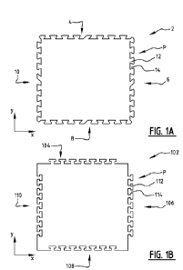
drawings, in which:
Figures 1 a and lb show examples of interlockable wall panels according to the
invention;
Figures 2a and 2b show detailed views of examples of projections and/or
indentations of an interlockable wall panel according to the invention;
Figures 3a, 3b and 3c show examples of a wall panel assembly according to the
invention;
Figure 4 shows a schematic cross-section of a wall that is reinforced using a
wall
panel assembly according to the invention; and
Figure 5 shows a schematic side view of figure 4.
In an example (see figure I a, 1b), interlockable wall panel 2, 102 is a wood
board,
such as an OSB-board or a multiplex board, that extends in a plane defined by
first
direction x and second direction y. Each side edge 4, 6, 8, 10, 104, 106, 108,
110 of
interlockable wall panel 2 is provided with an alternating pattern P of
projections 12, 112
and indentations 14, 114. It is noted that the presence of either projections
12, 112 or
CA 03219494 2023- 11- 17
WO 2022/245213
PCT/NL2022/050274
indentations 14, 114 on side edge 4, 6, 8, 10, 104, 106, 108, 110
automatically incurs the
presence of the other of projections 12 and indentations 14, 114. It is noted
that figure la
shows trapezoid projections 12, 112 and indentations 14, 114, whereas in
figure lb the
interlockable wall panel 2, 102 is provided with T-shaped projections 12, 112
and
5 indentations 14, 114.
In more detail (see figures 2a, 2b), it is shown that projections 112, 212 and
indentations 114, 214 can have different shapes to achieve the interlocking
effect
between interlockable wall panel 102 and second or further interlockable wall
panels (not
shown).
10 In a first example, projection 112 has a 1-shape, with bottom end
112b of the T
being connected side edge 104 of interlockable wall panel 102 and upper end
112a
projecting from side edge 104. Due to the shape of projection 112, indentation
114 is
automatically provided with an inverted 1-shape, in which bottom end 114b
points upward
in the second direction y and bottom end 114a is positioned at side edge 104.
This
15 alternating pattern allows interlockable wall panel 102 to be connected
to a second or
further interlockable wall panel in the third direction z (not shown) and
substantially
prevents any movement in the plane formed by first direction x and second
direction y.
In a second example (see figure 2b), projection 212 has a trapezium shape in
which small base 212b is located at side edge 204 and is connected therewith.
Large or
wide base 212a is located at some distance outwardly from side edge 204.
Indentation
214 has a mirrored position compared to projection 212. This means that small
base 214b
in this example is located upwardly from side edge 204, whereas wide or large
base 214a
is formed at side edge 204.
In an example of wall panel assembly 250 (see figures 3a and 3b), wall panel
assembly 250 comprises a plurality of interlockable wall panels 2, 102 that
are interlocked
with each other. Also shown are wall panel 254, having two 'flat' side edges
and two side
edges comprising an alternating pattern of projections and indentations, and
wall panel
252, which is provided with one 'flat' side edge and three side edges
comprising an
alternating pattern of projections and indentations. Wall panel assembly 252
can easily be
connected to a (not shown) wall to stabilize that wall. Figures 3a and 3b show
wall panel
assembly 250 having projections and indentations in respectively trapezoid
shape (figure
3a) and T-shape (figure 3b).
In an example of reinforced wall W (see figures 4 and 5), wall W is reinforced
or
stabilized using (a plurality of) interlockable wall panels 302 that in this
example are
positioned on opposite sides VV1, W2 of wall W. Interlockable wall panels 302
are in this
example connected to wall W using connection means 356, which may for example
be a
CA 03219494 2023- 11- 17
WO 2022/245213
PCT/NL2022/050274
16
bolt and nut connection. Similarly, ceiling C in this example is stabilized
using
interlockable wall panels 302'. The connection between interlockable wall
panels 302 and
interlockable wall panels 302' is in this case enhanced using connection beam
358. This
connection beam 358 is however not necessary to achieve the stabilization.
The present invention is by no means limited to the above described preferred
embodiments thereof. The rights sought are defined by the following claims
within the
scope of which many modifications can be envisaged.
CA 03219494 2023- 11- 17