Note: Descriptions are shown in the official language in which they were submitted.
WALL-MOUNTED AIR CONDITIONER
CROSS-REFERENCE TO RELATED APPLICATIONS
This application claims priority to and benefits of Chinese Patent Application
No.
202110611186.4, filed on June 1, 2021, the entire content of which is
incorporated herein by
reference.
FIELD
This application relates to the field of air conditioners, and more
particularly to a wall-
mounted air conditioner.
BACKGROUND
In the related art, an air inlet of a wall-mounted air conditioner is at its
top. In order to meet a
requirement for air inflow from the top, the wall-mounted air conditioner has
to be at a large
distance from an indoor top wall, resulting in low indoor space utilization
and making the indoor
space more cramped. Moreover, the wall-mounted air conditioner in the related
art has low heat
exchange efficiency.
SUMMARY
The present disclosure aims to solve at least one of the technical problems
existing in the
related art. Accordingly, embodiments of the present disclosure propose a wall-
mounted air
conditioner.
The wall-mounted air conditioner according to embodiments of the present
disclosure
includes: a housing, an electric control component, and a heat exchanger. An
air duct is arranged in
the housing, has an air inlet and an air outlet, and includes an air inflow
section and an air outflow
section connected to each other. At least a part of the air inlet is on a
front surface of the housing.
A mounting space is defined between a front plate of the housing and the air
duct and is in a front
and lower position within an internal space of the housing. The heat exchanger
is in the air duct,
and the electric control component is in the mounting space.
According to the present disclosure, since at least a part of the air inlet of
the wall-mounted
air conditioner is on the front surface of the housing, ambient air (air
inflow) can enter the air duct
substantially from the front of the housing. For example, the ambient air (air
inflow) can enter the
CA 03219863 2023- 11- 21
1
PIDM 12 1 22 72PCA
air duct from the straight front of the housing, or from the top front of the
housing, or from the
bottom front of the housing. In addition, the ambient air can enter the air
duct from at least two
directions selected from the straight front of the housing, the top front of
the housing, or from the
bottom front of the housing.
That is, the ambient air does not necessarily enter the air duct directly
above the housing. In
such a way, a distance between the wall-mounted air conditioner and an indoor
top wall can be
greatly decreased or even eliminated, and the utilization rate of indoor space
can be improved,
especially for indoor space (rooms) with lower heights, which can effectively
reduce or eliminate a
sense of crampedness of the indoor space.
Therefore, the wall-mounted air conditioner according to embodiments of the
present
disclosure has a very low requirement for mounting space. As long as the wall-
mounted air
conditioner can be accommodated in the mounting space, there is no need to
leave an air inflow
space above the wall-mounted air conditioner, which can expand the
applicability of the wall-
mounted air conditioner.
In some embodiments, the air inlet is located on the front surface, inclined
upwards towards
the wall surface (which can be understood as a mounting surface) relative to a
vertical surface. In
this way, when a user standing on the ground of the room, the user cannot see
the interior of the
housing (the wall-mounted air conditioner) through the air inlet, and internal
structures of the
housing (the wall-mounted air conditioner) are not exposed to the user, which
can improve the
user's visual comfort.
Moreover, in a scenario of air inflow from the top, the top space is often
restricted and
relatively narrow, which limits the air inflow volume due to the narrow top
space. In the technical
solutions of this application, since at least a part of the air inlet is
located on the front surface of
the housing, the air entering the air duct through the air inlet can directly
flow through the heat
exchanger for sufficient heat exchange with the heat exchanger. That is, the
air inflow volume of
the wall-mounted air conditioner is not limited by the narrow space at the
top. The air inflow from
the front surface of the housing can effectively increase the air inflow
volume and significantly
increase the air flow volume through the heat exchanger, greatly enhancing the
heat exchange
efficiency of the heat exchanger.
In the present disclosure, since at least a part of the air inlet is located
on the front surface of
the housing, there is no need to mount a roughly inverted V-shaped heat
exchanger below the air
CA 03219863 2023- 11- 21
2
PIDM1212272PCA
inlet, and it is unnecessary to mount a water receiving tray with a width
greater than or equal to a
width of the roughly inverted V-shaped heat exchanger at a lower end of the
heat exchanger, to
avoid failure in heat exchange of air with a part of the heat exchanger due to
the part being
obstructed by the water receiving tray. Since at least a part of the air inlet
is located on the front
surface of the housing, the water receiving tray will not prevent airflow from
flowing to the heat
exchanger. For example, the water receiving tray does not pass an airflow path
to the heat
exchanger, which can greatly improve the heat exchange efficiency of the heat
exchanger.
Optionally, the water receiving tray is located below the heat exchanger.
Therefore, the wall-mounted air conditioner in the embodiments of the present
disclosure has
advantages of easy installation, improved indoor space utilization, wide
applicability, and high
heat exchange efficiency.
In addition, the wall-mounted air conditioner in the embodiments of the
present disclosure
defines the mounting space in the front and lower position within the internal
space of the housing,
and the electric control component is mounted in this mounting space, so that
the electric control
component does not occupy the space in the length direction of the air
conditioner's body, which
decreases the length of the air conditioner's body and improves the space
utilization rate and
integration of the wall-mounted air conditioner, making the structure of the
wall-mounted air
conditioner more compact and reasonable. Moreover, the electric control
component will neither
occupy the effective air inlet area of the heat exchanger, nor sacrifice the
heat exchange efficiency
of the heat exchanger, improving the performance of the wall-mounted air
conditioner. In addition,
since the mounting space is located behind the front plate of the housing, the
user does not need to
remove the entire housing when wiring, assembling/disassembling, testing, or
repairing the electric
control component. Instead, the user only needs to remove the front plate,
which greatly improves
the convenience for testing and maintenance and enhances operational comfort.
Therefore, the wall-mounted air conditioner according to the embodiments of
the present
disclosure has advantages of high utilization rate of the internal space,
compact structure, small
length, and convenience for testing and maintenance.
In some embodiments, the air inlet is on the front plate; the air inflow
section extends
horizontally or obliquely forwards from the air outflow section; a part,
adjacent to the air outlet, of
the air outflow section extends downwards and forwards from a remaining part
of the air outflow
section; and the mounting space is defined among the air inflow section, the
air outflow section
CA 03219863 2023- 11- 21
3
PIDM1212272PCA
and the front plate.
In some embodiments, an air duct wall of the air inflow section includes a
first air inflow
plate and a second air inflow plate; an air duct wall of the air outflow
section includes a first air
outflow plate and a second air outflow plate; and the mounting space is
defined among the second
air inflow plate, the second air outflow plate and the front plate.
In some embodiments, the second air inflow plate includes a sunken part that
forms a water
receiving sink for receiving condensate water from the heat exchanger.
In some embodiments, the water receiving sink is on a first side of the sunken
part, and the
mounting space is on a second side of the sunken part.
In some embodiments, the wall-mounted air conditioner further includes a
thermal insulation
layer between the electric control component and the air duct.
In some embodiments, the electric control component includes: a protective
shell including a
box body and a box cover, the box body and the box cover being connected to
form a sealed
fireproof chamber; and an electrical component arranged in the fireproof
chamber.
In some embodiments, the electrical component includes a mainboard and
elements; the
mainboard is parallel to a bottom plate of the box body, and there is a gap
between the mainboard
and the bottom plate; the elements are mounted on a surface of the mainboard
away from the
bottom plate.
In some embodiments, the front plate is a curved plate protruding forwards and
includes an
upper plate portion and a lower plate portion; the air outlet is on the upper
plate portion; the
mounting space is behind the lower plate portion; the bottom plate is
obliquely arranged with a
lower end of the bottom plate being behind an upper end of the bottom plate.
In some embodiments, the elements include a first group of elements and a
second group of
elements; the first group of elements has a height greater than a preset
value; the second group of
elements has a height less than or equal to the preset value; and a position
of the second group of
elements is higher than a position of the first group of elements.
In some embodiments, an intersection angle between a centerline of the air
inflow section and
a centerline of the air outflow section is greater than or equal to 10 degrees
and less than or equal
to 85 degrees.
Additional aspects and advantages of embodiments of the present disclosure
will be given in
part in the following descriptions, become apparent in part from the following
descriptions, or be
learned from the practice of the embodiments of the present disclosure.
CA 03219863 2023- 11- 21
4
PIDM 12 1 22 72PCA
BRIEF DESCRIPTION OF DRAWINGS
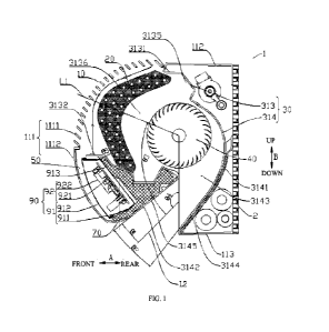
FIG. 1 is a sectional view of a wall-mounted air conditioner according to
embodiments of the
present disclosure.
FIG. 2 is a sectional view of a wall-mounted air conditioner according to
embodiments of the
present disclosure.
FIG. 3 is a schematic view of a wall-mounted air conditioner according to
embodiments of
the present disclosure.
FIG. 4 is a sectional view of a wall-mounted air conditioner in the related
art.
Reference numerals:
wall-mounted air conditioner 1, wall surface 2, top wall 3,
housing 10, front surface 11, front plate 111, rear surface 1110 of front
plate 111, upper plate
portion 1111, lower plate portion 1112, heat exchanger 20, air duct 30, air
inlet 311, air outlet 312,
air inflow section 313, first air inflow plate 3131, second air inflow plate
3132, side surface
31321, sunken part 3133, water receiving sink 3134, avoidance groove 3135,
inlet air duct 3136,
air outflow section 314, first air outflow plate 3141, second air outflow
plate 3142, side
surface 31421, outlet air duct 3143, first flat plate portion 3144, second
flat plate portion 3145,
fan wheel 40, mounting space 50, the water tank 60, thermal insulation layer
70,
electric control component 90, protective shell 91, box body 911, box cover
912, bottom plate
913, electrical component 92, mainboard 921, element 922,
centerline Li of air inflow section, centerline L2 of air outflow section,
intersection angle 0.
DETAILED DESCRIPTION
Embodiments of the present disclosure will be described in detail below, and
examples of the
embodiments will be shown in the accompanying drawings. The embodiments
described below
are exemplary and are intended to explain the present disclosure rather than
limit the present
disclosure.
The present disclosure is based on the inventors' discovery and understanding
of the
following facts and issues.
In the related art, as shown in FIG. 4, an air inlet of a wall-mounted air
conditioner 1' is
located at its top, and the top of the wall-mounted air conditioner 1' has to
be at a large distance
CA 03219863 2023- 11- 21
PIDM 12 1 22 72PCA
from an indoor top wall 3, to define an air inflow space. Consequently, the
wall-mounted air
conditioner l' cannot be arranged tightly against the indoor top wall 3. A
heat exchanger 10' of the
wall-mounted air conditioner l' is arranged around a cross-flow fan wheel 20'.
Specifically, a first
part 11' of the heat exchanger 10', which forms a roughly inverted V-shape, is
located above the
cross-flow fan wheel 20', and a second part 12' of the heat exchanger 10' is
located in front of the
cross-flow fan wheel 20'.
A water receiving tray 30' is provided below a rear lower end 111' of the
first part 11'. The
water receiving plate 30' is opposite to the rear lower end 111' of the first
part 11' in an up-down
direction and is located between the rear lower end 111' of the first part 11'
and the cross-flow fan
wheel 20'. The inventors have realized that the rear lower end 111' of the
first part 11' is
obstructed by the water receiving tray 30', such that the rear lower end 111'
of the first part 11'
does not exchange heat with air, resulting in waste and lowering heat transfer
efficiency.
An inlet air duct 50' is formed between the second part 12' and a front panel
40' of the wall-
mounted air conditioner 1'. However, the inventors have realized that since
most of the space in a
front-rear direction of the wall-mounted air conditioner l' is occupied by the
heat exchanger 10',
the cross-flow fan wheel 20' and a volute 60', the inlet air duct 50' is
relatively narrow, resulting in
a small air flow volume through the inlet air duct 50' and a low heat transfer
efficiency of the
second part 12'.
The inventors also find that an electric control component of the wall-mounted
air conditioner
in the related art is mounted on a side (e.g., a left side and/or a right
side) of a length direction of
the air conditioner's body. There are usually two situations: first, the
electric control component is
on the same side as a distributor and other pipeline systems; second, the
electric control
component and the pipeline systems such as the distributor are mounted on two
sides of the length
direction of the air conditioner's body respectively. However, regardless of
the first situation or the
second situation, the electric control component will occupy space along the
length direction of the
air conditioner's body, causing the air conditioner's body to be elongated. If
the length of the air
conditioner's body remains unchanged, the arrangement of the electric control
component on the
same side as the pipeline will reduce space for the pipeline and increase a
risk of scratches and
collisions with the pipeline. If the electric control component is mounted on
a side of a length
direction of the heat exchanger, it will occupy an effective air inlet area of
the heat exchanger,
thereby sacrificing the heat exchange efficiency of the heat exchanger.
Moreover, when the electric
CA 03219863 2023- 11- 21
6
PIDM1212272PCA
control component is mounted on the side of the length direction of the air
conditioner's body, a
housing of the air conditioner has to be removed during maintenance and
assembly/disassembly of
the electric control component, increasing the difficulty of maintenance.
A wall-mounted air conditioner 1 according to embodiments of the present
disclosure will be
described below according to FIGS. 1 to 3. As shown in FIG. 1, the wall-
mounted air conditioner 1
includes a housing 10, a heat exchanger 20, an air duct 30, and an electric
control component 90.
The air duct 30 is located inside the housing 10, and the heat exchanger 20 is
located inside the air
duct 30. The air duct 30 has an air inlet 311 and an air outlet 312, and the
air duct 30 includes an
air inflow section 313 and an air outflow section 314 connected to each other.
The air inlet 311 is
located in the air inflow section 313, and the air outlet 312 is located in
the air outflow section
314.
At least a part of the air inlet 311 is located on a front surface 11 of the
housing 10. The front
surface 11 of the housing 10 is a surface that can be seen by a horizontal
backward line of sight,
that is, a surface of the housing 10 that can be seen by the horizontal
backward line of sight is the
front surface 11 of the housing 10. For example, when an observer's eyes are
roughly at the same
level as the housing 10 and the observer is in front of the housing 10, a
surface of the housing 10
that the observer can see is the front surface 11 of the housing 10.
A front-rear direction is shown by arrow A in FIG. 1, and an up-down direction
is shown by
arrow B in FIG. 1. For example, the wall-mounted air conditioner 1 is mounted
on a wall surface
2. A direction away from the wall surface 2 in the horizontal direction
represents a forward
direction, and a direction away from the wall surface 2 in the horizontal
direction represents a
rearward direction.
There is a mounting space 50 between a front plate 111 of the housing 10 and
the air duct 30.
The electric control component 90 is within the mounting space 50. The
mounting space 50 is in a
front and lower position within an internal space of the housing 10, that is,
the electric control
component 90 is mounted in the front and lower position within the internal
space of the housing
10.
According to the present disclosure, since at least a part of the air inlet of
the wall-mounted
air conditioner is on the front surface of the housing, ambient air (air
inflow) can enter the air duct
substantially from the front of the housing. For example, the ambient air (air
inflow) can enter the
air duct from the straight front of the housing, or from the top front of the
housing, or from the
CA 03219863 2023- 11- 21
7
PIDM1212272PCA
bottom front of the housing. In addition, the ambient air can enter the air
duct from at least two
directions selected from the straight front of the housing, the top front of
the housing, or from the
bottom front of the housing.
That is, the ambient air does not necessarily enter the air duct directly
above the housing. In
such a way, a distance between the wall-mounted air conditioner and an indoor
top wall can be
greatly decreased or even eliminated, and the utilization rate of indoor space
can be improved,
especially for indoor space (rooms) with lower heights, which can effectively
reduce or eliminate a
sense of crampedness of the indoor space.
Therefore, the wall-mounted air conditioner according to embodiments of the
present
disclosure has a very low requirement for mounting space. As long as the wall-
mounted air
conditioner can be accommodated in the mounting space, there is no need to
leave an air inflow
space above the wall-mounted air conditioner, which can expand the
applicability of the wall-
mounted air conditioner.
In some embodiments, the air inlet 311 is located on the front surface,
inclined upwards
towards the wall surface 2 (which can be understood as a mounting surface)
relative to a vertical
surface. In this way, when a user standing on the ground of the room, the user
cannot see the
interior of the housing 10 (the wall-mounted air conditioner 1) through the
air inlet 311, and
internal structures of the housing 10 (the wall-mounted air conditioner 1) are
not exposed to the
user, which can improve the user's visual comfort.
Moreover, in a scenario of air inflow from the top, the top space is often
restricted and
relatively narrow, which limits the air inflow volume due to the narrow top
space. In the technical
solutions of this application, since at least a part of the air inlet is
located on the front surface of
the housing, the air entering the air duct through the air inlet can directly
flow through the heat
exchanger for sufficient heat exchange with the heat exchanger. That is, the
air inflow volume of
the wall-mounted air conditioner is not limited by the narrow space at the
top. The air inflow from
the front surface of the housing can effectively increase the air inflow
volume and significantly
increase the air flow volume through the heat exchanger, greatly enhancing the
heat exchange
efficiency of the heat exchanger.
In the present disclosure, since at least a part of the air inlet is located
on the front surface of
the housing, there is no need to mount a roughly inverted V-shaped heat
exchanger below the air
inlet, and it is unnecessary to mount a water receiving tray with a width
greater than or equal to a
CA 03219863 2023- 11- 21
8
PIDM1212272PCA
width of the roughly inverted V-shaped heat exchanger at a lower end of the
heat exchanger, to
avoid failure in heat exchange of air with a part of the heat exchanger due to
the part being
obstructed by the water receiving tray. Since at least a part of the air inlet
is located on the front
surface of the housing, the water receiving tray will not prevent airflow from
flowing to the heat
exchanger. For example, the water receiving tray does not pass an airflow path
to the heat
exchanger, which can greatly improve the heat exchange efficiency of the heat
exchanger.
Optionally, the water receiving tray is located below the heat exchanger.
Therefore, the wall-mounted air conditioner in the embodiments of the present
disclosure has
advantages of easy installation, improved indoor space utilization, wide
applicability, and high
heat exchange efficiency.
In addition, the wall-mounted air conditioner in the embodiments of the
present disclosure
defines the mounting space in the front and lower position within the internal
space of the housing,
and the electric control component is mounted in this mounting space, so that
the electric control
component does not occupy the space in the length direction of the air
conditioner's body, which
decreases the length of the air conditioner's body and improves the space
utilization rate and
integration of the wall-mounted air conditioner, making the structure of the
wall-mounted air
conditioner more compact and reasonable. Moreover, the electric control
component will neither
occupy the effective air inlet area of the heat exchanger, nor sacrifice the
heat exchange efficiency
of the heat exchanger, improving the performance of the wall-mounted air
conditioner. In addition,
since the mounting space is located behind the front plate of the housing, the
user does not need to
remove the entire housing when wiring, assembling/disassembling, testing, or
repairing the electric
control component. Instead, the user only needs to remove the front plate,
which greatly improves
the convenience for testing and maintenance and enhances operational comfort.
Therefore, the wall-mounted air conditioner according to the embodiments of
the present
disclosure has advantages of high utilization rate of the internal space,
compact structure, small
length, and convenience for testing and maintenance.
Specific embodiments according to the present disclosure will be described in
detail below in
conjunction with FIGS. 1 and 2. In some embodiments, the wall-mounted air
conditioner 1 is
mounted on the wall surface 2 indoors.
As shown in FIGS. 1 and 2, the wall-mounted air conditioner 1 includes the
housing 10, the
heat exchanger 20, the air duct 30 inside the housing 10, a fan wheel 40 in
the air duct 30, and the
CA 03219863 2023- 11- 21
9
PIDM1212272PCA
electric control component 90. The housing 10 includes the front plate 111,
and the air inlet 311 is
on the front plate 111. The electric control component 90 is mounted in the
mounting space 50
defined between the front plate 111 of the housing 10 and the air duct 30.
In some embodiments, when the housing 10 is mounted on the wall surface 2, a
distance
between a top surface of the housing 10 and the indoor top wall 3 is less than
or equal to 20
centimeters. In other words, a minimum distance between the housing 10 and the
indoor top wall 3
in the up-down direction is less than or equal to 20 centimeters. Hence, the
utilization rate of
indoor space can be further improved.
Optionally, the distance between the top surface of the housing 10 and the
indoor top wall 3 is
less than or equal to 15 centimeters. Alternatively, the distance between the
top surface of the
housing 10 and the indoor top wall 3 is less than or equal to 10 centimeters.
Alternatively, the
distance between the top surface of the housing 10 and the indoor top wall 3
is less than or equal to
8 centimeters. Alternatively, the distance between the top surface of the
housing 10 and the indoor
top wall 3 is less than or equal to 5 centimeters. Alternatively, the top
surface of the housing 10 is
in contact with the indoor top wall 3, i.e., the distance between the top
surface of the housing 10
and the indoor top wall 3 is equal to 0 centimeter. Hence, the utilization
rate of indoor space can be
further improved.
The air duct 30 includes the air inflow section 313 and the air outflow
section 314. The air
inflow section 313 forms an inlet air duct 3136, while the air outflow section
314 forms an outlet
air duct 3143. The air inlet 311 of the air duct 30 is at an end of the inlet
air duct 3136, and the air
outlet 312 of the air duct 30 is at an end of the outlet air duct 3143. The
heat exchanger 20 is
arranged inside the inlet air duct 3136 and at the air inlet 311. The heat
exchanger 20 is
corresponding to the air inlet 311 to exchange heat with air entering the
inlet air duct 3136 from
the air inlet 311.
A part of the fan wheel 40 is located in the inlet air duct 3136, and another
part of the fan
wheel 40 is located in the outlet air duct 3143. The fan wheel 40 is used to
generate air exhaust
force, allowing air entering the inlet air duct 3136 from the air inlet 311 to
subsequently enter the
outlet air duct 3143 through the fan wheel 40, and finally be discharged from
the air outlet. The
arrangement of the fan wheel 40 in the air duct 30 can increase the flow
volume and velocity of air
passing through the heat exchanger 20, to further improve the heat exchange
efficiency of the heat
exchanger 20 and the wall-mounted air conditioner 1.
CA 03219863 2023- 11- 21
PIDM 12 122 72PCA
As shown in FIG. 1, the air inflow section 313 obliquely extends forwards and
upwards from
the air outflow section 314. In other words, the air inflow section 313
obliquely extends forwards
and upwards from its connection with the air outflow section 314.
It should be noted that in other optional embodiments, the air inflow section
313 may also
extend horizontally forward from its connection with the air outflow section
314, or the air inflow
section 313 may also extend downwards from its connection with the air outflow
section 314.
Preferably, in some embodiments, the air inflow section 313 obliquely extends
forwards and
upwards from its connection with the air outflow section 314 to make the
structure of the wall-
mounted air conditioner 1 more reasonable.
A part, adjacent to the air outlet 312, of the air outflow section 314 extends
downwards and
forwards from a remaining part of the air outflow section 314. In other words,
the air outflow
section 314 includes the part adjacent to the air outlet 312 and the remaining
part except for that
part. The part, adjacent to the air outlet 312, of the air outflow section 314
extends downwards and
forwards from its connection with the remaining part. The air outlet 312 is
located at a lower part
of the housing 10.
The above arrangement of the air inflow section 313 and the air outflow
section 314 causes
the air duct 30 to be substantially V-shaped with an opening facing forwards,
and the air inflow
section 313 is above the part, adjacent to the air outlet 312, of the air
outflow section 313. The
mounting space 50 is defined among the air inflow section 313, the air outflow
section 314, and
the front plate 111. The electric control component 90 is mounted in the
mounting space 50. It can
be understood that the mounting space 50 is located in the front and lower
position within the
internal space of the housing 10. In other optional embodiments, the mounting
space 50 in the
front and lower position within the internal space of the housing 10 may be
formed by other
means, which will not be limited in the present disclosure.
As shown in FIGS. 1 and 2, in some embodiments, the front plate 111 is a
curved plate
protruding forwards, and the front plate 111 includes an upper plate portion
1111 and a lower plate
portion 1112. The upper plate portion 1111 is an upper portion of the front
plate 111, the lower
plate portion 1112 is a lower portion of the front plate 111, and the upper
plate portion 1111 is
above the lower plate portion 1112. The air outlet 312 is on the upper plate
portion 1111, and the
mounting space 50 is behind the lower plate portion 1112 and below the air
outlet 312.
Further, an air duct wall of the air inflow section 313 includes a first air
inflow plate 3131 and
CA 03219863 2023- 11- 21
11
PIDM 12 122 72PCA
a second air inflow plate 3132, and the inlet air duct 3136 is formed between
the first air inflow
plate 3131 and the second air inflow plate 3132. An air duct wall of the air
outflow section 314
includes a first air outflow plate 3141 and a second air outflow plate 3142,
and the outlet air duct
3143 is formed between the first air outflow plate 3141 and the second air
outflow plate 3142. For
example, the first air outflow plate 3141 is a volute tongue structure, and
the second air outflow
plate 3142 is a volute wheel structure.
The mounting space 50 is defined among the second air inflow plate 3132, the
second air
outflow plate 3142, and the front plate 111. Specifically, as shown in FIGS. 1
and 2, the mounting
space 50 is defined among a side surface 31321 of the second air inflow plate
3132 away from the
inlet air duct 3136, a side surface 31421 of the second air outflow plate 3142
away from the outlet
air duct 3143, and a rear surface 1110 of the front plate 111.
Optionally, the first air inflow plate 3131 and the first air outflow plate
3141 are connected to
form an integrated first wall, while the second air inflow plate 3132 and the
second air outflow
plate 3142 are connected to form an integrated second wall. The mounting space
50 is defined by
the second wall and the front plate 111.
As shown in FIGS. 1 and 2, the heat exchanger 20 is fitted at the air inlet of
the air inflow
section 313; an upper end of the heat exchanger 20 cooperates with the first
air inflow plate 3131,
and a first sealing structure (not shown) is provided between the upper end of
the heat exchanger
20 and the first air inflow plate 3131; a lower end of the heat exchanger 20
cooperates with the
second air inflow plate 3132, and a second sealing structure (not shown) is
provided between the
lower end of the heat exchanger 20 and the second air inflow plate 3132. The
first sealing structure
and the second sealing structure are used for sealing to prevent air, which
has not undergone heat
exchange with the heat exchanger 20, from entering the inlet air duct 3136 via
a gap between the
heat exchanger 20 and the first air inflow plate 3131 or between the heat
exchanger 20 and the
second air inflow plate 3132, which may otherwise affect a cooling effect of
the air conditioner.
Optionally, the first sealing structure and the second sealing structure are
sealing foam.
Since condensate water is generated during the heat exchange process of the
heat exchanger
20, in order to prevent the condensate water from flowing into the outlet air
duct 3143 and flowing
out from the air outlet 312, the second air inflow plate 3132 includes a
sunken part 3133 that forms
a water receiving sink 3134 for receiving the condensate water from the heat
exchanger 20, as
shown in FIGS. 1 and 2. The water receiving sink 3134 is on one side of the
sunken part 3133
CA 03219863 2023- 11- 21
12
PIDM1212272PCA
close to the inlet air duct 3136, and the mounting space 50 is on the other
side of the sunken part
3133. For example, the sunken part 3133 is formed in such a way that a part of
the second air
inflow plate 3132 is recessed in a direction away from the inlet air duct
3136. Alternatively, the
sunken part 3133 may also be seen as a part of the second air inflow plate
3132 protruding into the
mounting space 50. The mounting space 50 is on a side of the sunken part 3133
facing away the
water receiving sink 3134. Since the sunken part 3133 forms the water
receiving sink 3134, the
sunken part 3133 may also be called a water receiving tray.
In embodiments shown in FIGS. 1 and 2, the water receiving sink 3134 has an
opening facing
upwards, and the water receiving sink 3134 has a certain depth in the up-down
direction. The
water receiving sink 3134 is behind the lower end of the heat exchanger 20,
i.e., behind the second
sealing structure, and the water receiving sink 3134 is also below the heat
exchanger 20 to
effectively receive the condensate water of the heat exchanger 20.
Further, a part of the first air inflow plate 3131 is recessed outwards to
form an avoidance
groove 3135 that is located behind the upper end of the heat exchanger 20,
i.e., behind the first
sealing structure. The avoidance groove 3135 is used to avoid the condensate
water generated by
the heat exchanger 20 during the heat exchange process and to prevent the
condensate water from
flowing into the air outflow section 314 along the first air inflow plate
3131. Optionally, a part,
adjacent to the air outflow section 314, of the first air inflow plate 3131 is
recessed outwards to
form the avoidance groove 3135. For example, the avoidance groove 3135 is
formed in such a way
that a part of the second air inflow plate 3132 is recessed in a direction
away from the inlet air duct
3136, and the avoidance groove 3135 may also be seen as a part of the second
air inflow plate
3132 protruding outwards.
Further, in some embodiments, the wall-mounted air conditioner 1 also includes
a thermal
insulation layer 70 located between the electric control component 90 and the
air duct 30. In the
embodiments shown in FIGS. 1 and 2, the thermal insulation layer 70 is between
the second wall
and the electric control component 90. That is, the thermal insulation layer
70 is between the
electric control component 90 and the second air inflow plate 3132, as well as
between the electric
control component 90 and the second air outflow plate 3142. The arrangement of
the thermal
insulation layer 70 can achieve an anti-condensation effect and hence avoid
accidents that
endanger electric control safety.
As shown in FIGS. 1 and 2, in some embodiments, the electric control component
90 includes
CA 03219863 2023- 11- 21
13
PIDM1212272PCA
a protective shell 91 and an electrical component 92. The protective shell 91
includes a box body
911 and a box cover 912. The box body 911 and the box cover 912 are connected
to form a sealed
fireproof chamber. The electrical component 92 is in the fireproof chamber.
The above
arrangement improves the protection ability of the electric control component
90, prevents the
electrical component 92 from malfunctioning and catching fire, and enhances
the safety factor of
the wall-mounted air conditioner 1. Moreover, the electric control component
90 can be
independently disassembled, greatly improving the convenience for testing and
maintenance.
The electrical component 92 includes a mainboard 921 and elements 922. The
mainboard 921
is parallel to a bottom plate 913 of the box body 911, and there is a gap
between the mainboard
and the bottom plate. The elements 922 are mounted on a surface of the
mainboard 921 away from
the bottom plate 913. Optionally, the gap between the mainboard 921 and the
bottom plate 913 has
a size ranging 4 mm to 15 mm.
Further, in order to adapt to the mounting space 50, as shown in FIGS. 1 and
2, the bottom
plate 913 of the box body 911 is obliquely arranged, and a lower end of the
bottom plate 913 is
behind an upper end of the bottom plate 913. The above arrangement makes the
structure of the
wall-mounted air conditioner 1 more reasonable. There is an intersection angle
05 between the
bottom plate 913 and the vertical direction, and the intersection angle 05 is
greater than or equal to
0 degree but less than or equal to 90 degrees. A preferred value range of the
intersection angle 05
is greater than or equal to 30 degrees but less than or equal to 60 degrees,
in order to make the
installation of the electric control component 90 more suitable for the angle
of front plate 111 and
the shape of the mounting space 50, and make the structure of the wall-mounted
air conditioner 1
more reasonable.
As shown in FIGS. 1 and 2, a lower part of the fireproof chamber of the
protective shell 91
has a width greater than an upper part thereof. Further, the elements 922
include a first group of
elements and a second group of elements. The first group of elements has a
height greater than a
preset value; the second group of elements has a height less than or equal to
the preset value; and
the position of the second group of elements is higher than the position of
the first group of
elements. That is, the elements 922 include some elements 922 (the first group
of elements) with a
greater height, as well as some elements 922 (the second group of elements)
with a smaller height.
In some embodiments, in the electric control component 90, the first group of
elements with the
greater height is mounted below the second group of elements with the smaller
height, to make the
CA 03219863 2023- 11- 21
14
PIDM 12 122 72PCA
structure of the electric control component 90 more reasonable.
Additionally, in order to further improve the maintenance efficiency of the
electric control
component, a maintenance port is provided on the lower plate portion 1112 of
the front plate 111,
and the maintenance port is covered with a maintenance cover detachably
connected to the front
plate 111. When it is necessary to repair the electric control component 90,
the maintenance cover
is removed from the front plate 111 to expose the maintenance port.
Maintenance personnel can
have access to the electric control component 90 through the maintenance port,
without need to
remove the entire front plate 111. Hence, the maintenance process is more
convenient and
efficient.
In some embodiments, a rear surface of the first air inflow plate 3131 and/or
the first air
outflow plate 3141 is provided with a water tank 60 having an opening facing
upwards, and the
water tank 60 is arranged obliquely and connected to the water receiving sink
3134. The water
tank 60 is used to receive condensate water formed on the rear surface of the
first air inflow plate
3131 and/or the first air outflow plate 3141. The water in the water tank 60
will converge into the
water receiving sink 3134 and then be discharged together. The oblique
arrangement of the water
tank 60 means that the water tank 60 is arranged obliquely in its length
direction.
In the embodiments shown in FIGS. 1 and 2, the water tank 60 is arranged on a
rear surface
of the first wall. Further, the water tank 60 is at a rearmost position on the
rear surface of the first
wall to better receive the condensate water.
As an example, the water tank 60 extends along a length direction of the wall-
mounted air
conditioner 1 and is obliquely arranged. The water receiving sink 3134 also
extends along the
length direction of the wall-mounted air conditioner 1 and is obliquely
arranged. A tilt direction of
the water receiving sink 3134 is the same as a tilt direction of the water
tank 60. The length
direction of the wall-mounted air conditioner 1 is consistent with a length
direction of the air duct
30. The length direction of the air duct 30 is shown by arrow C in FIG. 3. A
lower end of the water
tank 60 is connected to a lower end of the water receiving sink 3134, so that
the water in the water
tank 60 will converge into the water receiving sink 3134. The lower end of the
water receiving
sink 3134 is connected to a drainage outlet inside the wall-mounted air
conditioner 1, so that the
water in the water tank 60 and the water receiving sink 3134 can be discharged
from the drainage
outlet.
As shown in FIGS. 1 and 2, the first air outflow plate 3141 includes a first
flat plate portion
CA 03219863 2023- 11- 21
15
PIDM1212272PCA
3144 adjacent to the air outlet 312, and the second air outflow plate 3142
includes a second flat
plate portion 3145 adjacent to the air outlet 312. Inner sides of respective
projections of the first
flat plate portion 3144 and the second flat plate portion 3145 are both
straight lines.
As shown in FIGS. 1 and 2, in a vertical plane perpendicular to the length
direction of the air
duct 30, a first intersection angle 01 between the second flat plate portion
3145 and a centerline of
the air outflow section 314 is greater than 0 degree and less than or equal to
30 degrees.
It is possible to reduce the space occupied by the outlet air duct 3143 while
ensuring the air
flow volume inside the outlet air duct 3143 (the air outflow volume of the
outlet air duct 3143), so
that the mounting space 50 is large enough to house the component (the
electric control
component 90), which is originally mounted on a side (such as a left side
and/or a right side) of the
air duct 30 in the length direction. The length of the wall-mounted air
conditioner 1 can be
effectively decreased, and the installation difficulty and space required for
the wall-mounted air
conditioner 1 can be reduced. A left-right direction is shown by arrow E in
FIG. 3.
Optionally, the first intersection angle 01 is greater than or equal to 1
degree and less than or
equal to 25 degrees. Alternatively, the first intersection angle 01 is greater
than or equal to 2
degrees and less than or equal to 20 degrees. Alternatively, the first
intersection angle 01 is greater
than or equal to 3 degrees and less than or equal to 10 degrees. The air flow
volume inside the
outlet air duct 3143 can be increased, and the capacity of the mounting space
50 can be enlarged,
further improving the cooling and heating effect of the wall-mounted air
conditioner 1, further
decreasing the length of the wall-mounted air conditioner 1, and further
reducing the installation
difficulty and space required for the wall-mounted air conditioner 1.
Optionally, the first intersection angle 01 may be but is not limited to 1
degree, 2 degrees, 3
degrees, 4 degrees, 5 degrees, 6 degrees, 7 degrees, 8 degrees, 9 degrees, 10
degrees, 15 degrees,
20 degrees, 25 degrees, or 30 degrees.
A second intersection angle 02 between the first flat plate portion 3144 and
the second flat
plate portion 3145 is greater than or equal to 5 degrees and less than or
equal to 45 degrees. It is
possible to reduce the space occupied by the outlet air duct 3143 while
ensuring the air flow
volume inside the outlet air duct 3143 (the air outflow volume of the outlet
air duct 3143), so that
the mounting space 50 is large enough to house the component (the electric
control component
90), which is originally mounted on the side (such as the left side and/or the
right side) of the air
duct 30 in the length direction. The length of the wall-mounted air
conditioner 1 can be effectively
CA 03219863 2023- 11- 21
16
PIDM1212272PCA
decreased, and the installation difficulty and space required for the wall-
mounted air conditioner 1
can be reduced.
Optionally, the second intersection angle 02 is greater than or equal to 10
degrees and less
than or equal to 40 degrees. Alternatively, the second intersection angle 02
is greater than or equal
to 10 degrees and less than or equal to 30 degrees. Alternatively, the second
intersection angle 02
is greater than or equal to 10 degrees and less than or equal to 20 degrees.
The air flow volume
inside the outlet air duct 3143 can be increased, and the capacity of the
mounting space 50 can be
enlarged, further improving the cooling and heating effect of the wall-mounted
air conditioner 1,
further decreasing the length of the wall-mounted air conditioner 1, and
further reducing the
installation difficulty and space required for the wall-mounted air
conditioner 1.
Optionally, the second intersection angle 02 may be but is not limited to 5
degrees, 10
degrees, 11 degrees, 12 degrees, 13 degrees, 14 degrees, 15 degrees, 16
degrees, 17 degrees, 18
degrees, 19 degrees, 20 degrees, 25 degrees, 30 degrees, 35 degrees, 40
degrees, or 45 degrees.
As shown in FIGS. 1 and 2, in the vertical plane perpendicular to the length
direction of the
air duct 30, a third intersection angle 03 between a centerline Li of the air
inflow section 313 and
a centerline L2 of the air outflow section 314 is greater than or equal to 10
degrees and less than or
equal to 85 degrees. It is possible to avoid significant changes in a flow
direction of air in the air
duct 30, in order to reduce flow resistance against the air and allow the air
to flow smoothly in the
air duct 30, further improving the cooling and heating effect of the wall-
mounted air conditioner 1.
Optionally, the third intersection angle 03 is greater than or equal to 20
degrees and less than
or equal to 80 degrees. Alternatively, the third intersection angle 03 is
greater than or equal to 40
degrees and less than or equal to 75 degrees. Alternatively, the third
intersection angle 03 is greater
than or equal to 60 degrees and less than or equal to 75 degrees.
Alternatively, the third
intersection angle 03 is greater than or equal to 70 degrees and less than or
equal to 75 degrees.
Consequently, the air can flow more smoothly in the air duct 30 and the
cooling and heating effect
of the wall-mounted air conditioner 1 can be further improved.
Optionally, the third intersection angle 03 may be but is not limited to 10
degrees, 15 degrees,
20 degrees, 25 degrees, 30 degrees, 35 degrees, 40 degrees, 45 degrees, 50
degrees, 55 degrees, 60
degrees, 65 degrees, 70 degrees, 71 degrees, 72 degrees, 73 degrees, 74
degrees, 75 degrees, 76
degrees, 77 degrees, 78 degrees, 79 degrees, 80 degrees, or 85 degrees.
As shown in FIGS. 1 and 2, in the vertical plane perpendicular to the length
direction of the
CA 03219863 2023- 11- 21
17
PIDM1212272PCA
air duct 30, a fourth intersection angle 04 between the centerline L2 of the
air outflow section 314
and a vertical upward direction is greater than or equal to 120 degrees and
less than or equal to 155
degrees. In such a way, the air leaving the outlet air duct 3143 can flow
downwards and forwards,
that is, the wall-mounted air conditioner 1 can discharge cold air (hot air)
downwards and
forwards, which can further improve the cooling and heating effect of the wall-
mounted air
conditioner 1. The vertical upward direction is shown by an upward arrow B in
FIG. 1.
Optionally, the fourth intersection angle 04 is greater than or equal to 130
degrees and less
than or equal to 150 degrees. Alternatively, the fourth intersection angle 04
is greater than or equal
to 140 degrees and less than or equal to 145 degrees. The flow direction of
the cold air (hot air)
discharged from the wall-mounted air conditioner 1 can be further optimized to
improve the
cooling and heating effect of the wall-mounted air conditioner 1.
Optionally, the fourth intersection angle 04 may be but is not limited to 120
degrees, 125
degrees, 130 degrees, 135 degrees, 140 degrees, 141 degrees, 142 degrees, 143
degrees, 144
degrees, 145 degrees, 150 degrees, or 155 degrees.
In conclusion, in the wall-mounted air conditioner 1 according to the
embodiments of the
present disclosure, the mounting space 50 is at the front and lower position
within the internal
space of the housing 10, and the electric control component 90 is mounted in
the mounting space
50. Compared to the traditional wall-mounted air conditioner, where the
electric control
component is mounted on the side of the length direction of the air
conditioner's body, the electric
control component 90 according to the embodiments of the present disclosure
does not occupy the
space in the length direction of the air conditioner's body. Under the
condition of the same width
and height, the wall-mounted air conditioner 1 according to the embodiments of
the present
disclosure has a shorter body length and a more compact structure. Moreover,
noise can be
reduced while the body length is maintained.
In addition, since the mounting space is located behind the front plate of the
housing, the user
does not need to remove the entire housing when wiring, disassembling,
testing, or repairing the
electric control component. Instead, the user only needs to remove the front
plate, which greatly
improves the convenience for testing and maintenance and enhances operational
comfort.
In the description of the present disclosure, it is to be understood that
terms such as "central,"
"longitudinal," "transverse," "length," "width," "thickness," "upper,"
"lower," "front," "rear,"
"left," "right," "vertical," "horizontal," "top," "bottom," "inner," "outer,"
"clockwise,"
CA 03219863 2023- 11- 21
18
PIDM1212272PCA
"counterclockwise," "axial," "radial" and "circumferential" should be
construed to refer to the
orientation as then described or as shown in the drawings under discussion.
These relative terms
are for convenience and simplicity of description and do not indicate or imply
that the devices or
elements referred to have a particular orientation and be constructed or
operated in a particular
orientation. Thus, these terms shall not be construed as limitation on the
present disclosure.
In addition, terms such as "first" and "second" are used herein for purposes
of description and
are not intended to indicate or imply relative importance or significance or
to imply the number of
indicated technical features. Thus, the feature defined with "first" and
"second" may comprise one
or more of this feature. In the description of the present disclosure, the
term "a plurality of" means
at least two, such as two or three, unless specified otherwise.
In the present disclosure, unless specified or limited otherwise, the terms
"mounted,"
"connected," "coupled," "fixed" and the like are used broadly, and may be, for
example, fixed
connections, detachable connections, or integral connections; may also be
mechanical or electrical
connections; may also be direct connections or indirect connections via
intervening structures;
may also be inner communication or interaction of two elements, which can be
understood by
those skilled in the art according to specific situations.
In the present disclosure, unless specified or limited otherwise, a structure
in which a first
feature is "on" or "below" a second feature may include an embodiment in which
the first feature
is in direct contact with the second feature, and may also include an
embodiment in which the first
feature and the second feature are not in direct contact with each other, but
are contacted via an
additional feature formed therebetween. Further, a first feature "on,"
"above," or "on top of' a
second feature may include an embodiment in which the first feature is right
or obliquely "on,"
"above," or "on top of' the second feature, or just means that the first
feature is at a height higher
than that of the second feature; while a first feature "below," "under," or
"on bottom of' a second
feature may include an embodiment in which the first feature is right or
obliquely "below,"
"under," or "on bottom of' the second feature, or just means that the first
feature is at a height
lower than that of the second feature.
Reference throughout this specification to "an embodiment," "some
embodiments," "an
example," "a specific example," or "some examples," means that a particular
feature, structure,
material, or characteristic described in connection with the embodiment or
example is included in
at least one embodiment or example of the present disclosure. Thus, the above
terms throughout
CA 03219863 2023- 11- 21
19
PIDM1212272PCA
this specification are not necessarily referring to the same embodiment or
example of the present
disclosure. Further, the particular features, structures, materials, or
characteristics may be
combined in any suitable manner in one or more embodiments or examples.
Moreover, those
skilled in the art can integrate and combine the different embodiments or
examples and the
features of the different embodiments or examples described in this
specification without
contradicting each other.
Although embodiments of the present disclosure have been shown and described,
it can be
appreciated by those skilled in the art that the above embodiments are merely
exemplary and are
not intended to limit the present disclosure, and various changes,
modifications, alternatives and
variations may be made to the embodiments within the scope of the present
disclosure.
CA 03219863 2023- 11- 21
20
PIDM1212272PCA