Note: Descriptions are shown in the official language in which they were submitted.
WO 2023/278165
PCT/US2022/033759
SMART SENSING FOR WATER AND WASTE SYSTEMS
CROSS REFERENCE TO RELATED APPLICATIONS
[0001] This application is related to and claims priority
benefits from U.S. Provisional
Application Serial No. 63/217,595, filed on July 1, 2021, entitled "Smart
Sensing for Water
and Waste Systems and Equipment: Prognostic and Health Management and
Augmented
Cabin," the entire contents of which are hereby incorporated in its entirety
by this reference.
FIELD OF THE INVENTION
[0002] The field of this disclosure relates to water and waste
systems for commercial
and military aerospace or other passenger transportation vehicles. Embodiments
allow for
diagnostic monitoring and predictive maintenance recommendations in order to
determine
whether one or more of the components of the equipment being monitored is in
need of repair
or replacement. Embodiments also provide for fault detection at the component
level, rather
than at the overall system level. If a fault is detected or predicted, the
component of the system
can be maintained, repaired or replaced during scheduled maintenance, rather
than removing
and replacing the wrong components, multiple components, causing operational
interrupts or
losing system functionality.
BACKGROUND
[0003] The advancement of digitization and sensor technology is
driving technical
discoveries in equipment and system prognostics and health management (PH1V1),
also known
as predictive health maintenance, in product design and operating solutions in
the aerospace
industry. There are established PHM platforms that focus on critical flight
systems, such as
engines and flight controls. However, there are other systems on board
aircraft and other
passenger transportation vehicles that can fail and cause serious problems,
one example of
which is the on-board water and waste system.
[0004] Additionally, on-board water and waste systems generally
have fault detection
at a system level. This means that if a system fails, the failure data will
typically indicate only
that the entire system has failed, not that a particular component in the
system or a working
element of a particular component in the system has failed. For example, if an
on-board
vacuum toilet stops flushing, the fault system will generally indicate a
problem with the overall
toilet system. However, the fault system typically does not indicate whether
the problem is
with the toilet flush valve, the vacuum generator, a system leak, a clogged
duct, or any other
type of specifics about what has caused the failure.
1
CA 03220237 2023- 11- 23
WO 2023/278165
PCT/ITS2022/033759
100051 Additionally, when the fault detection system sends an
alert about the problem,
the failure has already occurred. This can cause a problem if the aircraft is
in flight. This can
also cause a problem if there is a short turnaround time on ground and
engineering personnel
are not immediately available to troubleshoot, leading to flight delays.
100061 Accordingly, on-board water and waste systems could benefit from
both a more
detailed diagnostic/fault detection system, as well as a predictive health
maintenance system.
The present disclosure thus provides smart sensing for diagnostics and PHM in
connection with
water and waste equipment and systems on board aircraft and other passenger
transportation
vehicles. The application of PHM to the disclosed smart sensing of equipment
in water and
waste systems requires a different set of data analytics and parameters to be
monitored, distinct
from engines, flight controls, or other industrial applications.
SUMMARY
100071 The terms "invention," "the invention," "this invention"
and "the present
invention" used in this patent are intended to refer broadly to all of the
subject matter of this
patent and the patent claims below. Statements containing these terms should
be understood
not to limit the subject matter described herein or to limit the meaning or
scope of the patent
claims below. Embodiments of the invention covered by this patent are defined
by the claims
below, not this summary. This summary is a high-level overview of various
aspects of the
invention and introduces some of the concepts that are further described in
the Detailed
Description section below. This summary is not intended to identify key or
essential features
of the claimed subject matter, nor is it intended to be used in isolation to
determine the scope
of the claimed subject matter. The subject matter should be understood by
reference to
appropriate portions of the entire specification of this patent, any or all
drawings and each
claim.
100081 The present disclosure provides systems and methods for sensing and
monitoring equipment operation in the water and waste system for commercial
and military
aircraft (or any other passenger transportation vehicle) in order to provide
prognostic health
management (PHIM) for the equipment and the system. Equipment operation is
monitored and
measured to determine normal and abnormal system operation, detect system
and/or equipment
faults, and/or to isolate the abnormal operation or faults to specific
equipment, and/or to
identify failures or potential failures of specific working elements of a
component within the
system. The PHM system may sense a parameter (or set of parameters) "X" during
the
operation of the equipment and identify or otherwise detect a potential
failure of the equipment
CA 03220237 2023- 11- 23
WO 2023/278165
PCT/US2022/033759
based on comparing actual parameter "X" with expected parameter (or set of
parameters) "Y."
If the difference between the two parameters exceeds an expected set threshold
"T," a signal
can be generated to alert maintenance personnel, either onboard the vehicle or
at a maintenance
site, that a failure of the equipment is imminent. The disclosure allows for
detection and
isolation of failures of specific working elements of specific equipment
components within the
system, rather than only detecting an overall abnormal operation of the water
and waste system.
BRIEF DESCRIPTION OF THE DRAWINGS
[0009] FIG. 1 shows a flowchart of diagnostic and predictive
health maintenance.
[0010] FIG. 2 shows a diagram of failure modes that can be
isolated to a system or
component or working element level in accordance with this disclosure.
[0011] FIG. 3 shows a table of fault isolation, with normal and
abnormal operation
detection, outlining key sensors to be monitored for various faults, as well
as exemplary
suggested actions and detection approaches.
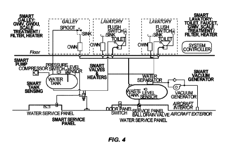
[0012] FIG. 4 shows various smart components that may be
designed for use in
connection with the water and waste system and in coordination with this
disclosure.
[0013] FIG. 5 shows an example of fault detection, showing a
difference in key system
parameters (waste tank pressure and vacuum generator current flow) from the
expected values
in a normal non-fault condition compared to the values sensed if the flush
valve failed closed.
[0014] FIG. 6 shows an example of fault detection, showing a
difference in key system
parameters (waste tank pressure and vacuum generator current flow) from the
expected values
in a normal non-fault condition compared to the values sensed if there is a
blockage.
DETAILED DESCRIPTION
[0015] The subject matter of embodiments of the present
invention is described
herewith specificity to meet statutory requirements, but this description is
not necessarily
intended to limit the scope of the claims. The claimed subject matter may be
embodied in other
ways, may include different elements or steps, and may be used in conjunction
with other
existing or future technologies. This description should not be interpreted as
implying any
particular order or arrangement among or between various steps or elements
except when the
order of individual steps or arrangement of elements is explicitly described.
[0016] The described embodiments of the invention provide a prognostic and
health
management smart sensing system for water and waste systems on board an
aircraft or other
passenger transportation vehicle. Although discussed in connection with an
aircraft system,
the prognostic and health management smart sensing system is by no means so
limited. Rather,
3
CA 03220237 2023- 11- 23
WO 2023/278165
PCT/US2022/033759
embodiments of the system may be used in connection with water and waste
systems on board
other vehicles, such as marine vessels, RVs, trains, or any other instance
where a water and
waste system would benefit from prognostic health management
[0017] Currently, equipment in the water and waste systems for
commercial and
military aircraft sometimes fail unexpectedly, resulting in operational
interruptions of the water
or waste system, potential turn backs of the flight, and unexpected
maintenance demands.
Additionally, it can be difficult to differentiate which specific equipment in
the system has
failed, making troubleshooting / fault isolation cumbersome, time consuming,
and can
contribute to NFF ("no fault found") removals when additional or incorrect
equipment is
removed from the aircraft.
[0018] Further, the move to more electric aircraft with controls
embedded equipment
and improved communication enables additional sensing within the equipment or
the system.
The data available in the monitoring and controls of this equipment is being
underutilized in
prediction of remaining useful life, in the detection of system operating
conditions, and on the
optimization of system operation and control. Additional equipment and system
sensing can
greatly expand the data analytic potential for the water and waste systems,
enabling it to be
monitored and included in existing or new PRM platforms.
[0019] The present disclosure offers solutions for the sensing
of equipment and the
water and waste system operational condition(s). The sensed condition(s) can
be used to both
(a) identify a current diagnostic issue/fault detection, as well as to (b)
predict remaining useful
life of the equipment. The sensed condition(s) can be used to further detect
and
distinguish/isolate between failure conditions of other equipment and its
working elements
within the system. The sensed condition(s) can also be used to detect
successful or
unsuccessful operation of associated equipment or the system.
[0020] This disclosure uses on-board sensors, and compares sensed values
with
expected values, in order to determine proper operation of on-board water and
waste
systems. Abnormal operation may need to be immediately addressed (fault
detection) or
anticipated to prevent more severe problems from manifesting (prognostic).
This disclosure
provides various examples and scenarios for an immediate or predictive
sensing. It should be
understood that the examples are provided for exemplary purposes only and are
not intended
to be limiting of the claims. In certain examples, sensor readings may be
compared across
time. Failures or potential failures may be predicted by considering data
collected from
multiple operations, or by analyzing trends, particularly for prognostic
failures. Particularly
4
CA 03220237 2023- 11- 23
WO 2023/278165
PCT/US2022/033759
meaningful data may be collected via comparison across an ensemble of sensed
data and across
time of equipment operation. Although specific examples may be described with
respect to a
single component of equipment or a single working element of an equipment and
a single
comparison between expected and threshold values, it should be understood that
a combination
of this analysis will often result in the most robust detection for both
immediate fault detection,
as well as prognostic health management.
[0021] The actions taken may then be one of (1) remove and
replace the failed
equipment (or equipment for which an imminent failure is predicted) or (2)
schedule a future
maintenance for the equipment.
[0022] This disclosure provides prognostic health management for various
components
of a water and waste system. Exemplary components that can be monitored and
maintained
using the methods and systems described in this disclosure include but are not
limited to
vacuum generators, air compressors, liquid pumps, toilets (toilet flush
valves, rinse valves),
various sensors (pressure, vacuum, current, liquid level), liquid separators,
water holding tanks,
waste holding tanks, heaters, transport elements, grey water evacuation units,
galley waste
disposal units, valves (of various actuation and control types), or any
combination thereof.
FIG. 4 illustrates exemplary systems/components in a water and waste system
that may be
monitored. In a specific example, the disclosed methods and systems monitor
the status of a
water and waste system, including the individual components within the system,
as well as the
individual working elements of the individual components within the system. In
one
embodiment, current performance values are compared against expected
performance values
in order to determine whether a system fault is likely imminent. If a
potential system fault is
detected, the component which is showing a predicted likely failure may be
repaired or replaced
or otherwise addressed before the actual fault occurs. Exemplary performance
values that can
be monitored in order to detect a potential fault include but are not limited
to vibration,
electrical current (motor drive current, motor controller input current,
heater current), pressure
level, humidity, rotational speed, flow, velocity, ventilation, temperature,
vacuum level,
sensing equipment operation, valve equipment operation, monitoring repeat
flush requests,
controller output signals, equipment fault messages, combinations of equipment
fault
messages, equipment change of state, user request commands, or any combination
thereof.
Diagnostic/Fault Isolation
[0023] In contrast to the prior methods of simply identifying
that a particular system is
failing (e.g., a vacuum toilet will not flush), the present disclosure relates
to sensing certain
5
CA 03220237 2023- 11- 23
WO 2023/278165
PCT/US2022/033759
specific values on various components of the system on their own, in order to
indicate to
maintenance personnel specifically where the particular problem is occurring.
Accordingly,
before removing and replacing the entire system from the vehicle at the system
level (e g ,
rather than removing and replacing the entire vacuum toilet), the operator may
now have more
detailed information in order to determine which specific working element of
the toilet is
expected to fail (or has failed) and should be replaced (e.g., the rinse ring
of the vacuum toilet
is clogged and should be replaced, with the toilet frame remaining installed).
[0024] For example, the observed system effect may be reduced
flush performance. A
system effect of reduced flush performance may be due to faulty toilet
assembly valve,
transport line clogging or leaks, inlet diverter fouling, vacuum generator
degradation, or other
failures. However, making use of key sensor and detection approaches, it is
possible to
determine more specifically at the component level what has actually caused
the failure. These
key sensors and detection approaches include comparing sensor values of the
tank vacuum
pressure, the vacuum generator current draw, vacuum pressure at other
locations in the vehicle,
7.5 other sensors, and those measurements over time on the vehicle. So
rather than removing the
entire toilet or system, the specific valve or other working element can be
repaired or replaced.
Similar analysis are outlined in this figure for a grey water interface valve
(GWIV), main line,
flow diverter, tank level, air water separator, vacuum generator, check valve,
tank drain, ball
valve, overboard line, drain mast, heaters, pumps, or other types of system
leaks.
[0025] FIG. 3 shows an additional set of examples. In a first example, a
toilet assembly
may have a rinse valve that is not operating properly. One or more sensors
associated with the
toilet assembly may be used to diagnose the issue. In an otherwise normal
flush, the water
system pressure drops during the rinse. If the water pressure does not drop
the expected
amount, this may signal that the rinse valve is not opening to let water flow,
and thus a
maintenance action should be raised. Further more detailed examples are
provided by FIG. 3.
It should be understood that these examples are provided for illustrative
purposes only and are
not intended to be limiting. Once one of ordinary skill in the art understands
the sensing
protocol disclosed and that individual components of an entire system can be
monitored, other
system failures, system effects, and suggested actions/detections may be
determined based on
data feedback from individual sensors.
[0026] FIG. 3 shows further fault isolation detection scenarios
that can be used to create
fault detection algorithms. For example, at the system/equipment level for the
toilet assembly
of Row 1, there are a number of different types of failures that may occur
(see Failure column)
6
CA 03220237 2023- 11- 23
WO 2023/278165
PCT/US2022/033759
which will result in differing system effects (see System Effect column).
These effects may be
detected via one or more sensors positioned on various working elements of the
smart toilet or
system Examples include but are not limited to a pressure sensors, vacuum
sensors, liquid
level sensors, valve position sensors, vibration sensors, current sensors, any
other appropriate
types of sensors, or any combination thereof. Exemplary working elements
include but are not
limited to the flush valve, rinse valve, rinse ring, main line, drain port, or
any combination
thereof
Predictive/Prognostic
[0027]
It is also possible to use the sensed data collected from the various
individual
sensors of the system to predict a potential failure. This aspect of the
disclosure uses PHM and
analyzes the gradual degradation vs. the immediate degradation of equipment or
sensed
parameters vs. components that have already failed. In this aspect, the PHM
system
incorporates (a) characterizations for the baseline performance of all
components of the system
being monitored and (b) overlays baseline performance over actual collected
data. This
comparison between measured values and expected values helps predict current
and future
health of the system.
[0028]
For example, expected performance parameters of a successful/normal
flush
may be modeled and a baseline performance can be determined. Relevant
parameters can
include tank waste volume, tank vacuum, vacuum generator current pull,
expected pressure
drop between the tank and the vacuum generator, expected time for flush valve
to stay open
and closed, expected flow rate, expected motor vibration, and any other
relevant, tracked
parameters. In one example, these parameters can be measured at different
times during a flush
(e.g., a 1.5 seconds, 3.5 seconds, and 7.5 seconds) in order to compare the
differences to an
expected baseline. For example, the parameters may be expected tank vacuum,
expected rate
of change of tank vacuum, and expected vacuum generator current. If there are
noticeable/quantifiable differences in performance between the expected
scenarios and actual
scenarios, an algorithm can be applied to identify the failure scenario.
In some
implementations, the algorithms are -supervised classification" machine
learning algorithms.
For example, -decision trees," which determine a set of questions/criteria to
result in a
categorization of failure mode. And another example, the algorithm can be
"nearest
neighbors," which identify a category of a point that is closest (e.g.,
Euclidean distance). Other
algorithms that match sensor data with expected results are possible. A system
can be trained
(known data in, known data out), which can lead to a predictive measurement.
This disclosure
7
CA 03220237 2023- 11- 23
WO 2023/278165
PCT/US2022/033759
relates to determining the inputs/values to be tested, generating the training
data, and
interpreting the results.
Example of updating failure probabilities over time
= Monitoring equipment either onboard or on the ground could track the
operating
state of the equipment, by maintaining a set of probabilities of failures
modes.
= The state of the equipment (set of failure probabilities) would be
initialized to
small values determined by analysis of historical failure rates from similar
equipment.
= For each use of the equipment (e.g. a flush, for vacuum waste systems).
1. Observe the actual sensors values, X
2. Determine expected values, Y, knowing the vehicle operating conditions,
given a
calibrated model
3. Update the state of failure probabilities based upon the difference between
X and
Y, taking into account the uncertainty in both sensor measurement and model
accuracy. This can be accomplished using algorithms such as Bayes' Theorem.
4. If any of the probabilities are above a determined threshold, T, the
difference should
be reported. It may take multiple iterations of equipment use (flushes) before
different failure scenarios can be distinguished.
Vacuum generator
[0029]
The vacuum generator used on board passenger transportation vehicles,
such as
aircraft, creates vacuum in the waste tank when commanded by various water and
waste system
equipment. This generated vacuum evacuates grey and black water or waste from
the various
equipment (most typically a vacuum toilet, but vacuum sinks may also be
installed in the
lavatory or galley and can also benefit from the systems of this disclosure)
to the waste tank.
(Pressure differential may be used in flight for creating vacuum, but when an
aircraft is on
ground, the vacuum generator is required to provide pressure differential to
create a vacuum.)
As background, a vacuum generator is a compressor which moves air from sub-
ambient
volumes to volumes at ambient pressure. Various parameters can be monitored to
detect the
normal and abnormal operation of the vacuum generator. In one example, it is
possible to
monitor the overall bearing and/or seal health of the vacuum generator by
analyzing vibration
levels, which can be calibrated to calculate remaining useful life of the
vacuum generator. Self-
induced vibration of the vacuum generator can be monitored in order to detect
a motor failure
or significant rub/ingestion event of the rotating elements. The self-induced
vibration can also
8
CA 03220237 2023- 11- 23
WO 2023/278165
PCT/US2022/033759
be used to detect the abnormal operating condition of waste system ingesting
water and/or
waste. For example, unexpected/normal vibration level of "X" may be compared
to the current
expected vibration level of "Y," and if the A (difference) between the two
levels is over an
acceptable threshold "T," then a signal can be generated, indicating that a
predicted failure is
likely, before an actual failure occurs.
[0030] In another example, the time expected for a vacuum
generator to reach its
working speed can be determined. If the vacuum generator takes longer than
some threshold
(such as a standard deviation) of the expected time to reach its working
speed, this is indication
of a potential fault or prediction of a future failure. The expected values
can be compared to
the sensed values in order to identify a current or potential problem.
[00M] In another example, the current drawn by the vacuum
generator, the resulting
waste tank pressures, and/or its temperature may be used to detect/distinguish
faults and
predictive failure conditions within the system. If a high level or low level
of current is detected
when not expected, this can indicate a problem in the system. For example, the
current drawn
by the vacuum generator may be used in combination with additional system
communication
to further detect and distinguish failure modes of equipment and the system in
a similar manner.
In another example, humidity within the vacuum generator can be used to detect
poor air/water
separation and/or abnormal conditions and/or poor maintenance leading to
contamination or
water/waste ingress into the vacuum generator and adjacent elements
[0032] In another example, rather than simply receiving a notification that
there is a
problem with the vacuum generator, use of various systems on various portions
of the vacuum
generator (VG) could instead issue a signal that "VG inlet blocked," which is
representative of
a clog somewhere in the waste system meaning that no flow is occurring during
the flush cycle.
Further sensors may specifically identify problems with individual working
elements of the
waste system, such as a clog in the main line trunk, a flow diverter or air
water separator
problem, or other indication.
[0033] In a further example, the current drawn by any other
component of the system,
system vacuum levels and/or the temperature of various components can be
monitored to detect
normal and abnormal operating conditions of the various equipment in the
system and to
detect/distinguish faults and failure conditions within the system. Events
that may be predicted
via such detection/monitoring include but are not limited to a normal
evacuation event, a clog
in the main trunk line, a clog in a branch line, a clogged air/water
separator, a clogged waste
tank diverter, clogged monument equipment, and/or broken valves. Various
expected values
9
CA 03220237 2023- 11- 23
WO 2023/278165
PCT/US2022/033759
may be assigned to each component in the system, and those expected values can
be compared
against actual current levels detected/monitored.
Air compressors/pumps
[0034] Displacement air compressors or more traditional
hydraulic pumps may be used
to pressurize the water system and circulate the water from the water tank to
the various
monuments. Monitoring the self-induced vibration of the air compressors can be
used to
predict remaining useful life of the air compressor. Monitoring the water
system pressure and
current draw of the air compressor/pump can be used to detect system leaks or
faulty water
system equipment Monitoring the self-induced vibration of the pump can be used
to detect
FOD (foreign object debris) ingestion, water starvation (i.e. zero water level
in the system) and
remaining useful life of the pump.
Smart toilet
[0035] As illustrated by the table FIG. 3, this disclosure may
also be implemented in
connection with a smart toilet assembly and various sensors mounted on
different working
elements of the toilet. Rather than simply sensing a failure or breakdown of
the entire toilet
system once it occurs, sensing expected values and comparing them to current
values can
indicate to an operator that a mechanical and/or electrical fault is predicted
(PHM).
Additionally or alternatively, sensing current values on their own, apart from
PHM, can
indicate to maintenance personnel where the particular problem is occurring.
In either instance,
before removing and replacing the entire toilet from the vehicle at the system
level, the operator
may now have more detailed information in order to determine which specific
working element
of the toilet is expected to fail (or has failed) and should be replaced.
[0036] For predictive health maintenance (PHM) in connection
with the smart toilet
example, an expected water pressure sensor reading "Yl" and an expected tank
vacuum sensor
reading "Y2" would be identified. Then, the actual sensed water pressure
sensor reading "Xi"
and the actual sensed tank vacuum sensor reading "X2" would be compared with
the expected
readings earlier identified. The system would run an algorithm to compare the
expected
readings with the actual readings and determine the difference (Al or A2)
there between. The
difference (Al or A2) is then compared with a PHM threshold for that
particular sensor (Ti or
T2) in order to determine whether the threshold has been exceeded.
Smart toilet flush valve example
[0037] In a Smart Toilet, the flush valve can potentially be
stuck open, and the
application of Smart Sensing can be used to detect and/or predict this. As an
example, consider
CA 03220237 2023- 11- 23
WO 2023/278165
PCT/US2022/033759
atypical system which may have a model calibrated to calculate expected vacuum
levels at -U-
0.75 inHg, and onboard vacuum sensors that can read +1- 0.25 inHg. The initial
"probability
flush valve is stuck open" may be determined from historical reliability data
as le-6
occurrences per use. Suppose, given the vehicle operating conditions, the
model predicts that
the value of vacuum sensor should be "p > 3.0 in Hg at t=9.0 sec of the flush
cycle" for normal
operation, and "p < 0.5 inHg at t=9.0 sec of the flush cycle- if the valve had
failed. Figure 5
depicts the predicted performance of the system under normal operation or if
the flush valve
was stuck open. If the vacuum sensor detects an actual vacuum level of "p=0.8
inHg at t=9.0
sec of the flush cycle", then the probability that the valve has failed open
can be increased
(using well-known statistical rules such as Bayes Theorem). In
this case, given the
uncertainties in the model and the measurement, the new probability that the
valve is stuck
open is 0.913. Under this analysis, a warning should be made due to the values
detected as
compared to the values expected, but under other circumstances, if the
probability was below
the threshold for warning, the value could be stored until the next flush to
await further data.
Various other examples that could indicate PHM issues include but are not
limited to:
[0038] a flush request followed by no change in system water
pressure could indicate
a clog in that particular rinse ring; or
[0039] a flush request followed by no change in system vacuum
pressure and without
a flush valve failure to open message could indicate a clog in the main line
or flow diverter;
or
[0040] a flush request followed by a continued reduction in
system water pressure
after the flush could indicate foreign object debris (FOD) in the rinse valve
(rinse valve stuck
open) or failure of the rinse valve components; or
[0041] a flush request followed by failure to regenerate vacuum
in the waste tank and
failure for flush valve to close message could indicate a clog in the flush
valve.
Air/Water Separator
[0042] A further example for which this disclosure can help
predict failure is in
connection with an air/water separator. In a normal working system, the
air/water separator
will require a baseline of current from a vacuum generator as it goes through
its cycle (in order
for it to create the required vacuum in the water tank). If the vacuum
generator gradually
increases current, this is an indication of a potential problem with the
air/water separator.
Other aircraft applications
11
CA 03220237 2023- 11- 23
WO 2023/278165
PCT/US2022/033759
[0043] The above examples of the equipment that can be monitored
for PHM capability
describe detection and isolation of equipment and system operational and fault
conditions.
Although described with respect to the on-board water and waste system,
similar applications
of smart sensing and extension to system operational / fault isolation
capability can be applied
to other aircraft systems. For example, this disclosure may apply to a fuel
pump / fuel system,
ventilation fan / environmental control systems, or any other appropriate
components that may
need to be (or can be) monitored for predictive health maintenance. For
example, fuel pump
characteristic performance may be able to detect fault conditions of adjacent
fuel system
equipment. In this instance, the parameters monitored and algorithms defined
would be
specific to the operating conditions and sensitivities of the fuel pump and
fuel system.
[0044] It is possible for a sensor to sense pressure
differential across various
components and equipment; to sense non-uniform vacuum, pressure, velocity
(these
parameters may be used to detect clogs); to sense content moving through the
transport
elements into the tank (these parameters may be used to detect clogs and/or
confirm equipment
operation); to sense water pressure (this parameter may be used to detect
water leaks or a pump
failure); to sense vacuum generation in the tank and/or vacuum generation in
the transport
elements (these parameters may be used to detect usage and isolate clogs).
[0045] In one example, a flush command (on a toilet in a
particular lavatory) on ground
which results in short time to vacuum (but no change in vacuum at t=3 sec when
the flush valve
should open) indicates a clog in the main line or flow diverter.
[0046] In another example, a grey water interface valve (GWIV)
flush command which
results in constant vacuum across the time duration for the GWIV flush and
with a toilet flush
at the same lavatory within the ¨ last 10 minutes which generated the typical
vacuum profile
in the tank could indicate a clog in the GWIV branch line or the GWIV. Whereas
the acceptable
toilet flush followed by triple request of GWIV to evacuate and low vacuum at
GWIV could
indicate a tear in the GWIV pinch valve / leak in the reservoir.
[0047] In another example implementation of diagnostic and
predictive health
monitoring, the monitored behavior deviating from anticipated behavior
expected from normal
and abnormal user interaction with the system can be indicative of component
failure or
adjacent system component failure. Smart equipment can then render themselves
temporarily
inoperative to prevent propagation of dam age or al arming equipment behavior.
Annunciation
of the deviated behavior can assist in diagnosis and repair of adjacent sub-
system equipment.
For example, a faulty motion activated flush switch may trigger the toilet
assembly to
12
CA 03220237 2023- 11- 23
WO 2023/278165
PCT/US2022/033759
constantly flush leading to offensive noise and early wear out of the toilet
assembly flush valve
or vacuum generator, as well as depletion of potable water. In this example, a
sudden increase
in toilet evacuation requests can be overridden by temporarily deactivating
the associated toilet
assembly. Similarly, a lavatory GWIV having normal evacuation behavior, but
with repeated
evacuation requests could be indicative of a failure of the valve in the
faucet leading to
offensive noise and early wear out of the vacuum generator as well as
depletion of potable
water. In this example, the repeated GWIV flush requests timed with the
flowrate of the faucet
can be overridden by temporarily restricting water to the associated lavatory
faucet.
[0048] This disclosure can help maximize operability of
subsystems by using second
and third Equipment Level data for PFIN/1. For example, as illustrated by FIG.
3, instead of
using data at Level 1 (e.g., toilet failure or toilet failure predicted), the
system can use data at
Level 2 and/or Level 3 to isolate potential problems of specific working
elements more
specifically. This can help ease operations for onboard and ground crews in
order to determine
which components are candidates for repair and replace and/or which components
may need
just a single internal working element repaired/replaced. By predicting near
end life of
equipment based on operating conditions, it is possible to prevent operational
interruptions,
improve logistics around maintenance, drive efficiency and repair stations,
provide long-term
refinement of equipment design, reduce turnaround time to avoid flight delays
and
cancellations, isolate failure causes and limit repairs, reduce repair costs,
and help avoid
subsequent failures. Other advantages of this disclosure are that it can help
identify problems
before they become immediate. For example, if time for flush valve increases
gradually over
time, this can be indicative of motor drive wear out. Increasing vibration
levels of pump or
vacuum generators can be indicative of bearing wear out. Time to pressurize
the water system
can be indicative of pump bearing wear out or an air compressor in-take filter
clog. Gradual
increase in time to vacuum in the waste tank (for a given monument location)
can be indicative
of Air/Water separator fouling/clog over time vs immediate faster time to
vacuum in the waste
tank is indicative of a clog in the flow diverter.
[0049] In the following, further examples are described to
facilitate the understanding
of the invention:
[0050] Example A. In one example, there is provided a method for diagnostic
and
predictive health management for a vehicle water and waste system, comprising:
(a) providing one or more sensors associated with one or more components of
the water and
waste system;
13
CA 03220237 2023- 11- 23
WO 2023/278165
PCT/US2022/033759
(b) collecting at least one actual sensed value (X1) from at least one of the
one or more sensors;
(c) comparing the sensed value with an expected value (Y1) for the component
from which the
sensed value was collected;
(d) determining a A difference between the sensed value and the expected value
(Al);
(e) comparing the A difference to a predetermined threshold value (T); and
(f) if the predetermined threshold value (T) is exceeded by the A difference,
recommending
scheduling preventive maintenance or replacing or repairing the one or more
components from
which the sensed value was collected.
[0051] Example B. The method of any of the preceding or
subsequent examples, further
comprising the one or more sensors comprising pressure sensors, vacuum
sensors, liquid level
sensors, valve position sensors, vibration sensors, current sensors, or any
combination thereof.
[0052] Example C. The method of any of the preceding or
subsequent examples, further
comprising wherein the one or more components of the water and waste system
comprise a
rinse valve, a flush valve, a pinch valve, a reservoir line, a vacuum tank, a
vacuum generator,
an air compressor, a transport line, a branch line, a water separator, a check
valve, a water tank,
a water pump, a toilet assembly, or any combination thereof.
[0053] Example D. The method of any of the preceding or
subsequent examples,
further comprising wherein the at least one actual sensed value (X1) from at
least one of the
one or more sensors comprises a plurality of sensed values over a set period
of time.
[0054] Example E. The method of any of the preceding or subsequent
examples, further
comprising wherein the at least one actual sensed value (X1) from at least one
of the one or
more sensors comprises a plurality of sensed values from a plurality of sensor
components.
[0055] Example F. The method of any of the preceding or
subsequent examples,
wherein the vehicle comprises an aircraft.
[0056] Example G. A further example provides a method for determining
failure or
fault of a working element at a component level instead of at a system-level
or at sub system-
level for a vehicle water and waste system, wherein the water and waste system
is comprised
of a plurality of equipment components, wherein each component is comprised of
a plurality
of working elements:
(a) providing at least one fault detection approach for at least one component
failure mode
under consideration;
(b) collecting sensed values (X) from that at least one fault detection
approach;
14
CA 03220237 2023- 11- 23
WO 2023/278165
PCT/US2022/033759
(c) comparing one or more collected sensed values (X) with one or more
expected values (Y)
for the working element from which the one or more collected sensed values
were collected;
(d) determining a A difference between the one or more collected sensed values
and the one or
more expected values (A);
(e) comparing the A difference to a predetermined threshold value (T); and
(f) if the predetermined threshold value (T) is exceeded by the A difference,
recommending
scheduling preventive maintenance or replacing or repairing the working
element of the
component rather than removing and replacing the entire component from the
water and waste
system.
[0057] Example H. The method of any of the preceding or subsequent
examples,
wherein the component comprises a vacuum toilet and wherein the plurality of
working
elements comprise a rinse valve, an anti-syphon valve, a flush valve, a rinse
ring, or any
combination thereof.
[0058] Example I. The method of any of the preceding or
subsequent examples,
wherein the component comprises a vacuum generator and wherein the plurality
of working
elements comprise a rotating group, electronic circuits, an impeller, an
auxiliary fan(s), or any
combination thereof.
[0059] Example J. The method of any of the preceding or
subsequent examples,
wherein the component comprises a pump and wherein the plurality of working
elements
comprise a rotating group, electronic circuits, an impeller, a check valve, or
any combination
thereof.
[0060] Example K. The method of any of the preceding or
subsequent examples,
wherein the component comprises an air compressor and wherein the plurality of
working
elements comprise a rotating group(s), a pressure chamber, an inlet filter, a
valve, an auxiliary
fan(s), or any combination thereof.
[0061] Example L. The method of any of the preceding or
subsequent examples,
wherein the component comprises a grey water interface valve and wherein the
plurality of
working elements comprises a reservoir, a filter, a valve, or any combination
thereof.
[0062] Example M. The method of any of the preceding or
subsequent examples,
wherein the component comprises a galley waste disposal unit and wherein the
plurality of
working elements comprises a reservoir, a flush valve, a rinse valve, an
actuation switch, or
any combination thereof.
CA 03220237 2023- 11- 23
WO 2023/278165
PCT/US2022/033759
[0063] Example N. The method of any of the preceding or
subsequent examples,
wherein the component comprises a waste tank assembly and wherein the
plurality of working
elements comprises a pressure vessel, an air/waste water separator, a level
sensor(s), or any
combination thereof.
[0064] Example 0. The method of any of the preceding or subsequent
examples,
wherein the component comprises a water tank assembly and wherein the
plurality of working
elements comprises a pressure vessel, a valve, a level sensor(s) , or any
combination thereof.
[0065] Example P. The method of any of the preceding or
subsequent examples,
wherein collecting one or more sensed values (X) from each of the at least one
fault detection
approaches comprises a plurality of sensed values over a set period of time.
[0066] Example Q. The method of any of the preceding or
subsequent examples,
wherein collecting one or more sensed values (X) from each of the at least one
fault detection
approaches comprises a plurality of sensed values from one or more working
elements of the
component.
[0067] Example R. The method of any of the preceding or subsequent
examples,
wherein the at least one fault detection approach comprises at least one
sensor associated with
at least one working component.
[0068] Example S. There is further provided a method for
determining failure or fault
of a working element at a component level instead of at a system-level or
subsystem-level for
a vehicle water and waste system, wherein the water and waste system is
comprised of a
plurality of equipment components, wherein each component is comprised of a
plurality of
working elements:
(a) sensing a plurality of component responses against a rule of expected
system responses;
(b) collecting the plurality of component responses;
(c) isolating failure of the component or the working element or both; and
(d) recommending scheduling preventive maintenance or replacing or repairing
the one or more
working elements or components or both from which the component responses were
collected.
[0069] It should be understood that different arrangements of
the components depicted
in the drawings or described above, as well as components and steps not shown
or described
are possible. Similarly, some features and sub-combinations are useful and may
be employed
without reference to other features and sub-combinations. Embodiments of the
invention have
been described for illustrative and not restrictive purposes, and alternative
embodiments will
become apparent to readers of this patent. Accordingly, the present invention
is not limited to
16
CA 03220237 2023- 11- 23
WO 2023/278165
PCT/US2022/033759
the embodiments described above or depicted in the drawings, and various
embodiments and
modifications may be made without departing from the scope of the claims
below.
17
CA 03220237 2023- 11- 23