Note: Descriptions are shown in the official language in which they were submitted.
WO 2022/256523
PCT/US2022/031955
PEDAL WITH ADJUSTMENT DIAL SYSTEM
CROSS-REFERENCE TO RELATED APPLICATIONS
[0001] This application claims the benefit of U.S. provisional
application Serial No.
63/195,804 filed June 2, 2021, the disclosure of which is hereby incorporated
in its entirety by
reference herein.
TECHNICAL FIELD
[0002] The present application relates to bicycle pedals, in
particular clipless pedals for use
with conventional shoes.
BACKGROUND
[0003] Cycling enthusiasts commonly use a cycling specific shoe
with a cleat on the underside
to attach their foot to a latching mechanism on the bicycle pedal. This allows
the user to apply force
to the pedal throughout the full circle of the pedal stroke. When using a shoe
with a platform cycling
pedal, the user is limited to only applying force in the downward vertical, or
near vertical, direction in
the pedal stroke. Adding a strapping mechanism to a platform pedal allows a
recreational cyclist to
wear a regular shoe and securely attach their foot to the pedal to gain the
associated benefits.
[0004] Some examples of prior pedals with clips include
US2019/0054977 for Pedal with
Detachable Shoe Platform and Adjustable Toe Clip; US4.953,425 for a Bicycle
Pedal Attachment;
US5,737,977 for a Selectively Releasable Toe Clip; US2004/0007090 for a
Securing Device for
Securing a Toe Strap on Pedal; US4,665,767 for a Bicycle Pedal with Foot
Holder; US2012/0137826
for a Supplementary Device for Bicycle Pedal and Bicycle Pedal; US4,638,685
for an Orthopedic
Safety Strap Suitable for Bicycle Pedals; U54,870,873 for a Bicycle Toe Clip;
US4,856,211 for a
Bicycle Pedal Foot Holder; US4,200,005 for a Pedal having an Improved Foot-
Retaining Strap Means;
1
CA 03220720 2023- 11- 28
WO 2022/256523
PCT/US2022/031955
US6,393,941 for a Toe Strap Receiving Device for a Pedal; and US4,386,472 for
Fixing Band for
Shoes.
SUMMARY
[0005] According to at least one embodiment, a pedal system is
provided and includes a rigid
pedal body being generally rectangular and having a generally planar support
surface. At least one
flexible strap is connected to the pedal body. An adjustment dial is secured
to at least one of the strap
or pedal body. A cord extends from the adjustment dial and cooperates with a
guide feature on the
pedal body or the flexible strap. A shoe opening is defined between the
support surface of the pedal
body, the strap and the cord. Rotation of the adjustment dial varies a length
of the cord, and thereby
adjusts a size of the shoe opening formed between the pedal body and the strap
and for adjustably
securing a rider's foot to the pedal body.
[0006] In another embodiment, the strap is secured to the pedal
body on a first side and the
cord is attached to the pedal body on a second side. The pedal body has a
guide hook on the second
side and the cord is attached guide hooks.
[0007] In another embodiment, the strap includes a forward strap
segment and an aft strap
segment, where the cord extends through guides on the forward and aft strap
and the cord is attached
to the pedal body at a forward hook and an aft guide hook.
[0008] In another embodiment, the strap has a length generally
equal to the length of the pedal
body.
[0009] In another embodiment, the strap is formed of a flexible
material preformed with a
curvature to form the adjustable shoe opening.
[0010] In another embodiment, the pedal body has two guide hooks
on the second side. The
strap has at least one guide hook, where the cord is attached to the guide
hooks.
[0011] In another embodiment, a first strap is secured to a first
side of the pedal body and a
second strap is secured to the second side of the pedal body. The cord is
attached to and extends
2
CA 03220720 2023- 11- 28
WO 2022/256523
PCT/US2022/031955
between the first and second straps. The adjustment dial is attached to one of
the first and second
straps.
[0012] In another embodiment, the pedal system may include a
third strap secured to the first
side of the pedal body, and a fourth strap is secured to the second side of
the pedal body. A second
cord extends between the third and fourth straps; and a second adjustment dial
is attached to the third
and fourth straps.
[0013] In another embodiment, the adjustment dial may include a
ratchet dial.
[0014] In another embodiment, the first and second straps are
formed of a flexible material
preformed with a curvature to form the adjustable shoe opening.
[0015] In another embodiment, the cord is attached to the pedal
body on a first side and a
second side. The strap is attached to the cord and defines a pressure plate
between the first and second
sides of the pedal body.
[0016] In another embodiment, the at least one strap is fixed to
the rigid pedal body at a first
end and the cord extends from a second end of the strap and is connected to a
guide feature.
[0017] In another embodiment, the ratchet dial rotates to reel
the cord into the ratchet dial in
one way and prevents the cord from reeling out of the dial until a release
mechanism in the dial is
actuated.
[0018] According to at least one embodiment, a pedal system is
provided for adjustably
securing a rider's foot to a pedal without a cleat. At least one strap is
connected to a pedal body. A
ratchet dial is secured to the strap. A cord extends from the ratchet dial to
form a loop, wherein the
loop cooperates with a guide feature on the pedal body or a strap. Rotation of
the ratchet dial varies a
length of the cord, and thereby adjusts a strap opening formed with the pedal
body.
[0019] According to at least one embodiment, the pedal system
also includes a rigid pedal
body having a generally planar support surface for supporting a rider's foot.
A dial-adjustment system
has at least one strap attached to the pedal body at a first end. A ratchet
dial is secured to the strap. A
cord is connected to the ratchet dial to form a loop. The cord extends from a
second free end of the
3
CA 03220720 2023- 11- 28
WO 2022/256523
PCT/US2022/031955
strap and cooperates with a guide feature on the pedal body or a strap. A
variable opening is defined
between the support surface of the pedal body, the strap and the cord.
Rotation of the ratchet dial varies
a length of the cord, and thereby adjusts a size of the opening for adjustably
securing the rider's foot
to the pedal body.
BRIEF DESCRIPTION OF THE DRAWINGS
[0020] FIG. 1 is a pedal with an adjustment dial system according
to one embodiment.
[0021] FIG. 2 is a pedal with an adjustment dial system according
to another embodiment.
[0022] FIG. 3 is a pedal with an adjustment dial system according
to another embodiment.
[0023] FIG. 4 is a pedal with an adjustment dial system according
to another embodiment.
[0024] FIG. 5 is a pedal with an adjustment dial system according
to another embodiment.
[0025] FIG. 6 is a pedal with an adjustment dial system according
to another embodiment.
[0026] FIG. 7 is a pedal with an adjustment dial system according
to another embodiment.
DETAILED DESCRIPTION
[0027] As required, detailed embodiments of the present invention
are disclosed herein;
however, it is to be understood that the disclosed embodiments are merely
exemplary of the invention
that may be embodied in various and alternative forms. The figures are not
necessarily to scale; some
features may be exaggerated or minimized to show details of particular
components. Therefore,
specific structural and functional details disclosed herein are not to be
interpreted as limiting, but
merely as a representative basis for teaching one skilled in the art to
variously employ the present
invention.
[0028] Typical pedal designs that use a plastic or metal cage
tightened with a strap and buckle
leave a loose length of strap when they are tightened that must be fed back
through another part of the
buckle as a secondary operation after tightening. If left loose, this strap
can catch on other parts of the
4
CA 03220720 2023- 11- 28
WO 2022/256523
PCT/US2022/031955
bicycle or in the environment and cause a hazard. The buckle on typical pedal
straps is also covered
by the extra length of strap and locating the buckle to loosen can be
difficult and take longer than
desired. The other disadvantage of the cage with strap design is discomfort.
The strap is narrow and
applies pressure over a very localized area over the top of the foot, and the
edge of the cage presses
into the top of the foot when properly tightened.
[0029] Other designs that consist of a single strap over the top
of the user's shoe only provide
retention in a single area of the shoe and result in less secure shoe
retention. Velcro closure systems
leave an extra length of strapping loose after securing similar buckle
systems. Straps secured by holes
in the strap and pins on the sides of the pedal often require dismounting the
bicycle and using both
hands to adjust the strap and cannot be adjusted while engaged in activity.
[0030] Cycling-specific shoes provide uniform and adjustable
retention of the user's foot in
the shoe. However, cycling-specific shoes must be used with specific pedal and
cleat combinations.
Cycling shoes are also typically difficult to wear for day-to-day activities
due to a rigid sole.
[0031] Some cycling platform pedals exist with a plastic or metal
cage and a woven strap with
metal buckle, or platform pedals with a single strap over the top of the user'
s foot and attached to the
platform on both sides, such as the self-tightening cage in U.S. Patent No.
6,510,764. Most of the prior
art pedals involve a buckle and clip mechanism, sometimes in conjunction with
incremental latching
features on the straps. Recently, bike pedal designs have moved towards a
clipless trend, and those
pedals do not include a toe clip fastening feature.
[0032] There are several advantages of using an adjustment dial
pedal system of the present
application over these prior designs. The tightening operation may be
performed with one hand and
may be done while sitting on the bike with feet on the pedals. The cord system
is completely self-
contained and does not have any loose or excess straps remaining after
tightening. The adjustment dial
allows for micro-adjustment of tension that allows the user to easily adjust
the pedal system for
comfort or security.
[0033] FIGS. 1-7 illustrate pedal systems with adjustment dials
and strap systems for use with
platform bicycle pedals. Using a strap with a platform pedal allows a
recreational cyclist to securely
attach their foot to the pedal while wearing a regular shoe and gaining
performance benefits of cycling-
CA 03220720 2023- 11- 28
WO 2022/256523
PCT/US2022/031955
specific shoes with cleats. Incorporating an adjustment dial system with the
strap is a new method that
provides a lightweight, completely self-contained, and easily adjusted strap.
The dial cords can be
minutely adjusted to a comfortable tension, and easily released to allow the
shoe to be freed.
[0034] Typical adjustment dial devices are incorporated in
footwear that is already sized to
correspond with the specific shoe or boot. One of the challenges of
incorporating an adjustment dial
with a pedal is that pedal systems should be adjustable to fit a large range
of shoes including both large
and small shoes. Most pedal cages do not properly fit shoes at the ends of the
spectrum. For example,
typical cages do not open large enough to allow large shoes to slide far
enough in, so the rider's foot
is not properly supported on the ball of the rider's foot. At the other end of
the spectrum, typical cages
can not be adequately tightened to small shoes when the shoes are properly
aligned on the ball of the
rider's foot.
[0035] The adjustment dial system 20 can also be easily expanded
to allow multiple users with
many different sized shoes to share the same exercise equipment and easily
adjust the pedal retention
tightness with a single hand while operating the equipment.
[0036] FIG. 1 illustrates a pedal system 100 according to one
example. As shown, the system
100 uses a dial-tensioned system to retain a shoe on a bicycle platform pedal
body 8. The adjustment
dial system 20 has a strap 6, a thin cord 2 and an adjustment dial 4 to adjust
an opening 40 for the
rider's foot.
[0037] The platform pedal body 8 is generally rectangular and has
a generally planar support
surface 38 to support the rider's foot. The support surface 38 may have grip
features or cut outs and
still be considered to have a generally flat or planar support surface. The
rider's shoe is placed on the
support surface 38 and within an adjustable opening 40 formed by the cord 2,
strap 6 and support
surface 38. Then the adjustment dial 4 is turned to reduce the length of the
cord 2 and tighten or
constrict the strap 6 against the rider's shoe.
[0038] The cord 2 may be low profile and completely contained
within the adjustment dial 4
and corresponding straps 6. When the adjustment dial system 20 is tightened,
the additional length of
cord 2 is coiled up within the dial 4 instead of hanging loose. To release the
tension on the adjustment
dial system 20, the user can manipulate an unlocking mechanism on the
adjustment dial 4. The dial 4
6
CA 03220720 2023- 11- 28
WO 2022/256523
PCT/US2022/031955
is always exposed and in the same location relative to the pedal 8 to allow
the user to easily adjust the
dial 4. Different styles of adjustment dials 4 may use different methods to
release tension and may
include, but not limited to: rotating dial in the opposite direction as when
tightening, pulling up on the
dial, or pulling on a lever attached to the face of the dial.
[0039] The adjustment dial system 20 can be used in several
configurations with the pedal
body 8. One example, shown in FIG. 1, uses the dial-tensioned system 20 and
has a strap 6 near the
aft edge of a pedal body 8 to wrap around the middle of the shoe and has a
plastic or metal cage 10
that may compress against the top of the user's shoe.
[0040] As shown in FIGS. 1-7, the adjustment dial 4 may have a
static base and a dial that is
allowed to rotate relative to it. The interface between the base and dial has
a ratcheting mechanism
built into it to allow rotation in one direction and resist rotation in the
opposite direction to reel in the
cord and prevent it from pulling loose. The dial may interface with the cord
on either one or both ends
of the cord, and hence can reel in the cord from a single end or both ends
simultaneously. A mechanism
also exists in the ratchet cord system to allow the tension on the dial to be
released and allow the cord
to be unrolled from the dial. The base can be directly manufactured into a
surface of the hardware by
methods such as molding or machining or may be created as a separate detail
that is sewn to a flexible
strap.
[0041] As shown in FIGS. 1-7, the cord may be routed from the
dial, through a guide that may
be eyelet or hook shaped on the strap or pedal, and then back to the dial.
When the cord is reeled in, it
is reeled from both sides of the cord simultaneously, but due to the geometry
of the dial it may not be
evenly taken up into the dial the same amount on both ends. Hence, the cord is
allowed to slide through
the guide as the cord is tightened. The length of cord that the dial can take
up as it is tightened can
vary based on the type of dial used. In one example, the dial that can take up
7-10 inches of cord into
the dial. Other suitable lengths of cord may be used.
[0042] The adjustment dial 4 may be a ratchet dial or dial-
tensioning device that allows
incremental ratcheting rotational adjustment of the cord or other cable or
tension element. The cord
can be wound and unwound by the ratchet-dial to allow adjustment of a loop of
the cord. The ratchet-
dial can control rotation control and lock the dial so the dial maintain
tension and prevent the cord
7
CA 03220720 2023- 11- 28
WO 2022/256523
PCT/US2022/031955
from being unwound or loosened. For example, the ratchet-dial may include
ratchet gears with teeth
and pawls to interact with the ratchet gear and provide one-way winding and
torque control. The
adjustment dial 4 may also include other one-way mechanisms such as roller
bearings, clutches, as
well as other mechanisms.
[0043] The cord 2 may be made of high strength polymer, braided
metal or braided metal
coated with polymer. In one example, the cord has a cross-section between
0.5mm and 1.5mm in
diameter. Other cord materials, cables or tension elements having other
dimensions may also be used.
[0044] The strap 6 may be made from a flexible material that is
able to carry a moderate tensile
load from end to end. Typical materials used to make straps include woven
fabric, woven webbing,
leather, foam and plastic, or a combination of these and other materials.
[0045] The pedal body 8 is the platform and surface that the
rider's shoe rests on and may be
made of plastic or metal or any suitable material with rigidity and stiffness
for the rider to apply pedal
force. The pedal body 8 may have a pedal platform adapter that can snap into a
spring-loaded -clip" on
the face of the pedal that is used with a cycling specific shoe with cleats.
The pedal body 8 may have
a cleat-feature on one side that cooperates with the clip. The clip and
corresponding cleat-feature may
be different styles such as Look Keo, Look Delta, Shimano SPD, Shimano SPD-SL,
Crankbrothers
Eggbeater, Time ATAC, Wahoo Speedplay and/or other style/brand of clip and
cleat-features. On the
opposite side from the cleat-feature, the pedal body 8 may be a large,
generally flat platform surface
for the user to place their non-cycling specific shoe.
[0046] The adjustment dial and guides may be made of metal or
plastic, or a combination
thereof. Guides 12 may be shaped as eyelets, hooks or channels that allow the
cord to slide through
during tightening.
[0047] In the pedal system 100 in FIG. 1, the adjustment dial 4
replaces a traditional toe-cage
webbing and metal buckle strap. An adjustment dial system is sewn into the
strap 6 that can be routed
through the pedal body 8 and through the toe cage features 10. The end of the
strap opposite the
adjustment dial contains a guide 12. The cord 2 is routed from the dial 4.
through the guide 12 and
back to the dial 4 to form a continuous loop between the dial 4 and the guide
12. The combination of
8
CA 03220720 2023- 11- 28
WO 2022/256523
PCT/US2022/031955
the strap 6 with the routed cord form a continuous loop through the pedal body
8 and toe cage 10.
When the adjustment dial is turned, the cord 2 is reeled into the dial body to
tighten the strap 6.
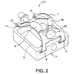
[0048] In another embodiment shown in FIG. 2, a pedal system 200
uses a single adjustment
dial 4 with a cord 2 routed back and forth over the top of the user's shoe and
attached to the platform
pedal body 8 on both sides of the shoe. By tightening the single dial 4, the
entire cord 2 is shortened
and tightened evenly around the shoe.
[0049] In the pedal system 200 in FIG. 2, the adjustment dial
system 20 tightens two straps 6
with a single dial 4. The adjustment dial system is sewn into a strap 6 that
is attached to the first side
26 of the pedal body 8 and has features to route the cord 2 over the user's
foot to the second side 28
of the pedal. The cord 2 is routed from the adjustment dial 4 over the foot
and through a first hook 14
on the opposite side of the pedal 8, then back over the foot and through
another guide feature 18 near
the adjustment dial 4, over the foot and through a second hook 14 on the
opposite side of the pedal 8
and finally routed back to the adjustment dial 4. Similarly, the cord 2 may be
routed from the dial 4
through guides 16 attached to straps 6 that are attached to the second side 28
of the pedal body 8 and
the straps 6 pass over the top of the foot. When the adjustment dial 4 is
turned, the cord is reeled into
the dial body 4 and the cord 2 is tightened uniformly on both the forward and
aft straps 6.
[0050] Another embodiment in FIG. 3 shows a pedal system 300 that
uses multiple adjustment
dials 4 to tighten separate sets of cords 2 attached to the sides of the pedal
body 8 and routed over the
top of the user's shoe. The dials 4 can be tightened independently to adjust
the tightness over different
areas of the user's shoe. As shown, the pedal system 300 has a first strap 30
and is secured to a first
side 26 of the pedal body 8 and a second strap 32 secured to the second side
28 of the pedal body 8.
One cord 2 is attached to and extends between the first and second straps 30,
32. One adjustment dial
4 is attached to one of the first and second straps 30, 32. A third strap 34
secured to the first side 26 of
the pedal body 8, and a fourth strap 36 is secured to the second side 28 of
the pedal body 8. A second
cord 2 extends between the third and fourth straps 34, 36. A second adjustment
dial 4 is attached to
the third and fourth straps 34, 36.
[0051] In the example layout in FIG. 3, multiple adjustment dial
systems tighten multiple
straps over a pedal body. A first adjustment dial 4 is sewn into the first
strap 30 that is attached to first
9
CA 03220720 2023- 11- 28
WO 2022/256523
PCT/US2022/031955
side 26 of the pedal body 8 and the cord 2 is routed from the first adjustment
dial 4 through a guide
12, as shown. The cord 2 may also be routed from the first adjustment dial 4
to a hook or guide on
the opposite side 28 of the pedal then back over the foot to the adjustment
dial 4. Similarly, the guide
12 may be attached to a strap that is attached to the second side 28 of the
pedal body 8 and passes over
the top of the foot. As shown, a second adjustment dial 4 is sewn into the
third strap 34 that is attached
to the first side 26 of the pedal body 8 and the cord 2 is routed from the
second adjustment dial 4
through a second guide 12, as shown. The strap arrangement may be repeated
multiple times at
different locations on the pedal body. When the adjustment dial is turned, the
cord is reeled into the
dial body and the cord is tightened independently in each strap.
[0052] FIG. 4 illustrates a pedal system 400 according to another
embodiment having a wide
strap 22. The wide strap 22 may be attached to pedal body 8 with various
methods. For example, the
wide strap 22 may be attached with a fastener or hook and loop attachment,
sewn or bonded or other
suitable method. The wide strap 22 may also be attached with an interference
fit such as a molded pin
on the pedal body that engages an aperture on the wide strap 22. The wide
strap 22 may be formed of
rubber, plastic, leather, natural or synthetic fibers or other suitable
flexible material. The wide strap
22 may be pre-formed with a curvature. The curvature may also a user easier
access to the adjustable
shoe opening.
[0053] The wide strap 22 is secured to a first side 26 of the
pedal body 8 and a second wide
strap 24 is secured to the second side 28 of the pedal body 8. The cord 2 is
attached to and extends
between the first and second wide straps 22, 24 and the adjustment dial 4 is
attached to one of the wide
straps 22, 24.
[0054] The wide straps 22, 24 provide more contact area to better
secure the rider's foot to the
pedal body. The cord 2 extends between the first and second straps 22, 24 to
allow the straps to be
moved apart while a rider inserts their foot and then can be tightened
together. The cord 2 may be
routed in a crisscross configuration and attached to hooks 14 or guide
features on the straps 22, 24.
The adjustment dial 4 is attached to one of the straps 22, 24 adjacent a free
end. As shown in FIG. 4,
the wide straps 22, 24 may have a length generally equal to the length of the
pedal body 8. The straps
22, 24 may be less or more than the length of the pedal body 8 while still
providing a large contact
CA 03220720 2023- 11- 28
WO 2022/256523
PCT/US2022/031955
area to secure the rider's foot to the pedal body. In another embodiment, the
wide straps 22, 24 may
have a length of at least 50% of the length of the pedal body 8.
[0055] FIG. 5 illustrates a pedal system 500 according to another
embodiment having a wide
strap 22 attached to pedal body 8 with various methods discussed above. A
first end 42 of wide strap
22 is secured to a first side 26 of the pedal body 8. The adjustment dial 4
and cord 2 are secured to a
second free end 44 of the wide strap 22. The cord 2 is attached to and extends
between the wide straps
22 and the second side 28 of the pedal body.
[0056] FIGS. 6-7 illustrate pedal systems where a wide strap 22
may not be secured to the
pedal body 8 and instead floats above the support surface 38. The cord 2 is
attached to pedal body 8
on a first side 26 and a second side 28. The strap 22 is attached to the cord
2 and defines a pressure
plate between the first and second sides 26, 28 of the pedal body. As shown in
FIG. 6, the pedal
system 600 has hooks 14 or guide features on each of the first and second
sides 26, 28. The adjustment
dial 4 is mouthed on the strap 22 and the cord 2 extends over the strap 22.
The strap 22 may include
a tongue 46 for the user to grasp the strap 22 as they insert their foot in
the opening 40. Having open
sides may allow the user to insert their shoe more easily in the opening 40.
The wide strap 22 provides
good contact and would conform to the top of the user's shoe. FIG. 7 shows a
pedal system 700 with
additional hooks 14 or guide features defined on the wide strap.
[0057] While exemplary embodiments are described above, it is not
intended that these
embodiments describe all possible forms of the invention. Rather, the words
used in the specification
are words of description rather than limitation, and it is understood that
various changes may be made
without departing from the spirit and scope of the invention. Additionally,
the features of various
implementing embodiments may be combined to form further embodiments of the
invention.
11
CA 03220720 2023- 11- 28