Note: Descriptions are shown in the official language in which they were submitted.
90814155/0083239-4D3
SYSTEMS, METHODS, AND DEVICES FOR FACILITATING ACCESS TO TARGET
ANATOMICAL SITES OR ENVIRONMENTS
[0001] The present application claims priority to U.S. Application No.
61/235,004, filed August
19, 2009 and U.S. Application No. 61/300,794, filed February 2, 2010.
TECHNICAL FIELD
[0002] The present disclosure relates generally to systems, methods, and
devices for facilitating
access to a target anatomical site. More specifically, aspects of the present
disclosure relate to
systems, methods and devices that can include one or more sensing units or
sensors configured to
indicate or verify whether an object, probe, or needle is inserted into a
target or a non-target
anatomical site, structure, or substance.
BACKGROUND
[0003] Needles and catheters are routinely inserted or injected into a
patient's body for various
purposes or indications. One type of indication that involves such insertion
is the placement of
vascular lines or catheters, for instance, the placement of a central venous
catheter (CVC). A CVC
is typically used to administer fluids (e.g., intravenous (IV) drugs,
chemotherapeutic agents, blood,
or saline) into the body in medical situations in which large fluid transfer
volume and/or high fluid
transfer rate is desired. Common CVC insertion targets include an internal
jugular vein, located in
the neck; a subclavian vein, located in the chest; or a femoral vein, located
in the groin. A medical
procedure known as the Seldinger technique is typically employed for placing
CVCs within the
body.
[0004] The Seldinger technique involves several steps. To establish venous
access and CVC
insertion via the Seldinger technique, a needle is first placed or inserted
into the patient's body at a
location expected to correspond to a target vein. A guidewire is then advanced
or extende
1
Date Recue/Date Received 2023-11-27
WO 2011/022073 PCT/US2010/002305
through the needle into the vasculature or vessel in which the needle resides.
The needle is
subsequently removed while a portion of the guidewire remains retained within
the vessel, and a
portion of the guidewire remains outside the patient's body. Next, a CVC is
advanced over the
guidewire into the vessel. Finally, the guidewire is removed, leaving a
portion of the CVC within
the vessel.
[0005] One problem that can arise during CVC placement via the Seldinger
technique is a
misplacement of either or both of the needle and the CVC. For example, an
unintended puncture
or tear of a venous wall and/or the placement of one or both of the needle and
the CVC into an
artery (i.e., an unintended arterial cannulation) can occur, which may result
in serious and
expensive complications including severe bleeding, emergency vascular surgery,
stroke, and
possibly death.
[0006] Manometry is a technique that has been used for verifying that an
appropriate type of
blood vessel has been targeted during catheterization (e.g., in association
with the Seldinger
technique). Conventionally, during manometry directed toward vascular target
verification, an
extension set (e.g., a 50 centimeter extension tube set) is attached to a
needle or a catheter (e.g.,
an 18-gauge needle or catheter) that has been inserted into a vessel. Blood
flows from the
patient's body into the needle or catheter, and further flows into an elevated
section of tube along
the extension set, thereby forming a blood column.
[0007] Visible properties of the blood column within the elevated section of
tube are assessed
by a surgeon or other medical personnel. The assessment of the blood column,
for example, a
height attained by the blood column, gives an indication as to the pressure of
the blood within the
vessel under consideration. Such an assessment can enable the surgeon to
verify a venous or an
arterial placement of the needle or the catheter. However, needle or catheter
occlusion or patient
state or condition can impact the visible properties of the blood column, and
hence the surgeon's
assessment, which can lead to a false conclusion about needle or catheter
placement. For
instance, in a hypotensive patient, an inadvertent arterial needle insertion
may not be readily
apparent from a naked-eye assessment of blood column height within the
elevated section of
tube.
[0008] Additionally, it has been found that many physicians do not routinely
utilize
manometry for verifying needle or catheter placement. Furthermore, a needle or
a catheter may
become dislodged or displaced after performing manometry, which may render its
vascular
location uncertain. Accordingly, the risk of accidental arterial cannulation
during CVC insertion
2
Date Recue/Date Received 2023-H-27
WO 2011/022073 PCT/US2010/002305
procedures has not been eliminated by the use of manometry. It has also been
suggested that the
use of manometry may increase the risk of infection or air embolism within the
patient.
10009] Ultrasound has been conventionally utilized for determining the
position of objects
within the body, including needles, guidewires, and catheters. However, images
captured with
ultrasound may not be adequately informative or clear. For example, ultrasound
may be unable
to accurately or consistently differentiate between certain tissue types (e.g.
between venous
tissue and arterial tissue). There have been reported instances of accidental
arterial cannulation
during CVC placement despite the use of ultrasound. In addition, ultrasound
systems or
apparatuses belonging to a medical facility are typically shared among
multiple groups or
departments of that medical facility, and hence may not always be readily
available.
Additionally, the use of ultrasound for verifying vascular targeting can be
time consuming, and
thus may be undesirable in critical or emergency situations. Furthermore, the
use of ultrasound
systems can be comparatively costly and labor intensive.
BRIEF SUMMARY OF THE INVENTION
[0010] The present invention provides systems, devices, and related methods
for facilitating
access to a target anatomical site, which can include detecting or monitoring
a physiologic
parameter of an anatomical environment in a patient.
100111 In one embodiment, the present invention includes a device for
selectively indicating
whether an end of a probe inserted into a body is located within a target
anatomical environment
or a non-target anatomical environment. The device can include a housing
detachably couplable
to the probe; a chamber carried by the housing; a sensing unit in
communication with the
chamber, the sensing unit carried by the housing; a processing unit coupled to
the sensing unit
and carried by the housing, the processing unit configured to determine a
first physiologic
parameter value using the first set of sensing signals and a second
physiologic parameter value
using at least one of the first set of sensing signals and the second set of
sensing signals, the first
and second physiologic parameter values respectively corresponding to a first
physiologic
parameter and a second physiologic parameter within an anatomical environment;
and a set of
output devices coupled to the processing unit and carried by the housing, the
set of output
devices configured to output a set of reporting signals corresponding to at
least one of the first
physiologic parameter value and the second physiologic parameter value,
wherein the second
physiologic parameter value differs from the first physiologic parameter value
in at least one of a
3
Date Recue/Date Received 2023-11-27
WO 2011/022073 PCT/US2010/002305
physiologic measurement type and a set of mathematical operations applied to
at least one of the
first set of sensing signals and the second set of sensing signals.
[0012] In another embodiment, a method for determining whether a substance
acquired from a
body and present within a substance analysis chamber corresponds to a target
anatomical
location is provided. The method includes establishing at least one from the
group of signal
communication and substance communication between a set of sensing devices and
the
substance present within the substance analysis chamber, the set of sensing
devices comprising at
least a first sensing device, each sensing device within the set of sensing
devices operating in
accordance with a sensing modality; acquiring a plurality of sensing signals
using the set of
sensing devices; determining a first physiologic parameter value and a second
physiologic
parameter value using the plurality of sensing signals, the second physiologic
parameter value
differing from the first physiologic parameter value in at least one of
corresponding to a different
sensing device modality and corresponding to a different set of mathematical
operations applied
to at least one of the first set of sensing signals and the second set of
sensing signals; and
.. outputting a set of signals that actively indicates whether the substance
corresponds to the target
anatomical location.
100131 In yet another embodiment, a device having a processing unit configured
to generate an
active indication of a probe end positioning at a target anatomical site or an
active indication of a
probe end positioning at a non-target anatomical site is provided. Such a
device can include a
housing couplable to a probe; a chamber carried by the housing; a sensing unit
in communication
with the chamber; a processing unit coupled to the sensing unit and carried by
the housing; an
electronically programmable medium storing program instructions for causing
the processing
unit to perform the steps of: determining a first physiologic parameter value
using a sensing
signal(s); and generating a reporting signal(s) that indicates whether the
probe is positioned in
.. the target anatomical location or the non-target anatomical location; and
an output device(s)
coupled to the processing unit.
[0014] In another embodiment, a device for indicating whether an end of a
probe inserted into
a body is located within a first anatomical environment or a second anatomical
environment is
provided. The device can include a housing having a first port; a chamber
coupled to the first
port and carried by the housing; a sensing unit in at least one of signal and
substance
communication with the chamber, the sensing unit carried by the housing, the
sensing unit
configured to generate a plurality of sensing signals in accordance with at
least one sensing
4
Date Recue/Date Received 2023-11-27
WO 2011/022073 PCT/US2010/002305
modality; a processing unit coupled to the sensing unit and carried by the
housing, the processing
unit configured to determine a plurality of physiologic parameter values using
the plurality of
sensing signals; a set of output devices coupled to the processing unit and
carried by the housing,
the set of output devices configured to actively output a first set of
reporting signals
corresponding to the first anatomical environment and configured to actively
output a second set
of reporting signals corresponding to the second anatomical environment.
[0015] In yet another embodiment, the present invention provides a device for
detecting
whether a distal portion of a probe inserted into a body is located within a
target anatomical
environment. The device can include a housing having a distal portion with a
first port that is
detachably couplable to the probe, and a proximal portion with a second port
that is detachably
couplable to a syringe, and the first port fluidly coupled to the second port;
a pressure sensing
unit carried by the housing, the sensing unit configured to generate a
pressure signal in response
to a pressure of an environment in which a coupled probe is positioned; a
processing unit
coupled to the sensing unit and carried by the housing, the processing unit
configured to receive
the pressure signal and determine based on the signal a pressure value of the
environment about
the proximate portion of the coupled probe; and an output unit coupled to the
processing unit and
carried by the housing, the output unit configured to output to a visual
display a reporting signal
based on the determined pressure value, wherein the pressure sensing unit,
processing unit, and
output unit are disposed substantially between the first port and the second
port of the housing.
10016] In another embodiment, the present invention includes a device
including a housing
having a proximal portion and a distal portion with a first port that is
detachably couplable to the
probe. The device further includes a pressure sensing unit carried by the
housing; a processing
unit coupled to the sensing unit and carried by the housing; and an output
unit coupled to the
processing unit and carried by the housing; and a guidewire port carried by
the housing and
.. fluidly coupled to the first port.
[0017] In yet another embodiment, a device is included, the device having a
housing having a
distal portion with a first port that is detachably couplable to the probe,
and a closed proximal
portion; a pressure sensing unit carried by the housing; a processing unit
coupled to the sensing
unit and carried by the housing; and an output unit coupled to the processing
unit and a visual
display, and carried by the housing, wherein the visual display is angled
proximally as carried by
the housing, wherein the pressure sensing unit, processing unit, and output
unit are disposed
substantially between the first port and the proximal portion of the housing.
5
Date Recue/Date Received 2023-H-27
90814155/0083239-4D3
[0018] The present invention, in yet another embodiment, provides
methods for detecting or
monitoring a physiologic parameter of a patient. Such a method includes
providing a device as
described herein, inserting a distal portion of a probe coupled to the device
into a tissue or body
of a patient, and detecting a physiologic parameter of an environment in which
the probe is
positioned.
[0019] The present invention, according to yet another embodiment,
further provides kits or
packaged assemblies. A kit can include a device as described herein and one or
more probes for
coupling to the first port, syringe(s), a guidewire(s), or a catheter(s), or a
combination thereof.
[0019A] Aspects of the disclosure relate to a device for selectively
indicating whether an end
of a probe inserted into a body is located within a target anatomical
environment or a non-target
anatomical environment, the device comprising: a housing having a first port
that is detachably
couplable to the probe and a second port in fluid connection to the first
port; a chamber coupled
to the first port and carried by the housing; a sensing unit in at least one
of signal and substance
communication with the chamber, the sensing unit carried by the housing, the
sensing unit
configured to generate a pressure signal in response to a tissue pressure of
an environment in
which the distal portion of the probe is positioned, the tissue pressure
signal comprising a series
of instantaneous tissue pressure values; a processing unit coupled to the
sensing unit and carried
by the housing, the processing unit configured to receive and process the
series of instantaneous
tissue pressure values so as to determine a mean tissue pressure value using a
moving average of
the series over a predetermined time, the mean tissue pressure value
indicative of the tissue
environment about the distal portion of the probe; and an output unit coupled
to the processing
unit and carried by the housing, the output unit configured to output to a
visual display a
reporting signal comprising the mean tissue pressure value; wherein the
sensing unit, the
processing unit, and the output unit are disposed substantially between the
first port and the
second port of the housing and wherein the housing, the distal portion of the
probe and the
display are manipulatable together in order to place the probe in response to
the mean tissue
pressure using the moving average of the series.
[0019B] Aspects of the disclosure relate to a method for detecting positioning
of a probe in a
tissue of a patient having a spinal canal, comprising: providing a device
comprising a housing
having a proximal portion and a distal portion, the distal portion coupled to
the probe, the device
further comprising: a tissue pressure sensing system at least
6
Date Recue/Date Received 2023-H-27
90814155/0083239-4D3
partially carried by the housing and comprising a processing unit coupled with
a pressure sensor,
the processing unit configured to receive tissue pressure signals comprising a
series of
instantaneous tissue pressure values from the pressure sensor and determine a
mean tissue
pressure value over a predetermined period of time with a moving average of
the series, the
mean tissue pressure value indicative of a tissue environment about a distal
portion of the
coupled probe; and an output unit carried by the housing and comprising a
visual display, the
output unit coupled to the pressure sensing system so as to receive the mean
tissue pressure value
signal and output to the visual display the determined mean tissue pressure
value, thereby
indicating positioning of the probe in the tissue of the patient; advancing
the output unit and the
probe distally such that a distal portion of the probe advances through the
tissue of the patient
and toward the patient's spinal canal with the mean tissue pressure shown on
the visual display;
and detecting a change in the mean tissue pressure value about the distal
portion of the coupled
probe during said advancing indicating probe positioning in the patient's
spinal canal.
[0019C] Aspects of the disclosure relate to a device for detecting positioning
of a coupled
probe in a tissue of a patient, the device comprising: a housing having a
distal portion with a first
port that is detachably couplable to a probe, and a proximal portion, the
housing graspable with a
hand of a user to advance the housing and the probe toward the tissue; a
tissue pressure sensing
system at least partially carried by the housing and comprising a processing
unit coupled with a
pressure sensor, the processing unit configured to receive tissue pressure
signals comprising a
series of instantaneous tissue pressure values from the pressure sensor and
determine from the
received signals a mean tissue pressure value over a predetermined period of
time with a moving
average of the series, the mean tissue pressure value indicative of a tissue
environment about a
distal portion of the coupled probe, the predetermined period of time selected
such that the mean
tissue pressure value is indicative of a position of the distal portion of the
coupled probe during
positioning in tissue; and an output unit carried by the housing and
comprising a visual display,
the output unit coupled to the pressure sensing system so as to receive the
mean tissue pressure
value and output to the visual display a reporting signal indicating the
determined mean tissue
pressure value, thereby indicating positioning of the probe in the tissue of
the patient.
[0019D] Aspects of the disclosure relate to a device for detecting positioning
of a coupled
probe in a tissue of a patient, the device comprising: a tissue pressure
sensing system at least
partially carried by a housing and comprising a processing unit coupled with a
pressure sensor,
6a
Date Recue/Date Received 2023-H-27
the housing graspable with a hand of a user and couplable to a probe having a
distal portion, the
processing unit configured to receive a plurality of pressure signals
comprising a series of
instantaneous tissue pressure values from the pressure sensor and determine
from the plurality of
pressure signals a mean tissue pressure value over a predetermined period of
time with a moving
average of the series selected such that the mean tissue pressure value is
indicative of a position
of the distal portion of the coupled probe during positioning in tissue; and
an output unit carried
by the housing and comprising a visual display, the output unit coupled to the
pressure sensing
system so as to receive the mean tissue pressure value and the series of
instantaneous tissue
pressure values and output to the visual display the determined mean tissue
pressure value and
the series of instantaneous pressure values, thereby indicating positioning of
the probe in the
tissue of the patient, wherein the visual display comprises a readout display
carried with the
housing for displaying both the determined mean tissue pressure value and the
series of
instantaneous tissue pressure values in order to position the probe with
movement of the housing
and the readout display.
[0019E] Aspects of the disclosure relate to a device for positioning a probe
in tissue of a
patient, the device comprising: a housing comprising a gripping portion and
having a distal
portion with a first port that is detachably coupleable to a probe such that
the probe is rigidly
attached to the distal portion, and a proximal portion having a second port
fluidly coupled to the
first port, wherein the first port and second port are disposed on the housing
such that the
coupled probe, device and second port are arranged axially and in sequence; a
tissue pressure
sensing system at least partially carried by the housing and comprising a
processing unit coupled
with a pressure sensor to receive a plurality of pressure signals comprising a
series of
instantaneous pressure values from the pressure sensor and determine from the
plurality of
pressure values a mean tissue pressure value over a predetermined period of
time with a moving
average of the series, the mean tissue pressure value indicative of a tissue
environment about a
distal portion of the rigidly coupled probe, the predetermined period of time
being selected such
that the mean tissue pressure value is indicative of a position of the distal
portion of the coupled
probe during positioning in tissue; and an output unit carried by the housing
and comprising a
visual display carried by the housing, the output unit coupled to the pressure
sensing system so
as to receive the mean tissue pressure value and output to the visual display
the mean tissue
6b
Date Recue/Date Received 2023-H-27
pressure value determined with the moving average of the series, thereby
indicating positioning
of the probe in the tissue of the patient.
[0019F] Aspects of the disclosure relate to a medical device, comprising: a
housing having a
distal portion with a first port that is detachably couplable to a probe, and
a proximal portion
with a second port that is detachably couplable to a syringe, the first port
fluidly coupled to the
second port, the housing graspable by a user to manipulate the housing and the
probe; a pressure
sensor carried by the housing, the sensor configured to generate a pressure
signal in response to a
pressure of a tissue environment in which a distal portion of the probe is
positioned, the pressure
signal comprising a series of instantaneous pressure values; a processing unit
coupled to the
sensor, the processing unit configured to receive and process the series of
instantaneous pressure
values so as to determine a pressure value using a moving average of the
series over a time
period, the pressure value indicative of the tissue environment about the
distal portion of the
probe; and an output unit coupled to the processing unit and carried by the
housing, the output
unit configured to wirelessly output the series of instantaneous pressure
values.
[0019G] Aspects of the disclosure relate to a medical device, comprising:
a housing having a distal portion with a first port that is detachably
couplable to a probe, a
proximal portion with a second port, and a chamber to transfer fluid in
response to action of a
plunger, the first port fluidly coupled to the second port, the housing
graspable by a user to
manipulate the housing and the probe; a pressure sensor carried by the
housing, the sensor
configured to generate a pressure signal in response to a tissue pressure of a
tissue environment
in which a distal portion of the probe is positioned, the tissue pressure
signal comprising a series
of instantaneous tissue pressure values; a processing unit coupled to the
sensor, the processing
unit configured to receive and process the series of instantaneous tissue
pressure values so as to
determine a tissue pressure value using a moving average of the series over a
time period, the
tissue pressure value indicative of the tissue environment about the distal
portion of the probe;
and an output unit coupled to the processing unit and carried by the housing,
the output unit
configured to output a reporting signal.
[0019H] Various embodiments of the claimed invention relate to a medical
device, comprising:
a housing having a distal portion with a fluid port that is detachably
couplable to a probe, and a
chamber to receive bodily fluid from the fluid port, the housing graspable by
a user to
manipulate the housing and the probe; a processing unit coupled to a fluid
pressure sensor
6c
Date Recue/Date Received 2023-H-27
associated with the chamber to generate pressure signals, the processing unit
configured to
receive and process electrical signals from an external sensor, wherein the
external sensor is an
electrocardiography (EKG) lead that electrically communicates with the
processing unit; and
an output unit coupled to the processing unit and carried by the housing, the
output unit
configured to output a reporting signal.
[0020] For a fuller understanding of the nature and advantages of the
present invention,
reference should be made to the ensuing detailed description and accompanying
drawings. Other
aspects, objects and advantages of the invention will be apparent from the
drawings and detailed
description that follows.
BRIEF DESCRIPTION OF THE DRAWINGS AND TABLES
[0021] FIG. lA is a perspective illustration of an apparatus for indicating a
probe segment or
probe tip location according to an embodiment of the disclosure.
[0022] FIG. 1B is a block diagram of an anatomical environment
characterization device
(AECD) according to an embodiment of the disclosure.
[0023] FIG. 1C is a block diagram of a device according to another embodiment
of the
disclosure.
[0024] FIG. 2A is a perspective illustration of an apparatus for indicating a
probe segment or
probe tip location according to another embodiment of the disclosure.
[0025] FIG. 2B is a cross sectional illustration of a webbed o-ring structure
according to an
embodiment of the disclosure.
[0026] FIG. 2C is a cross sectional illustration of the webbed o-ring
structure of FIG. 2B in a
sealing configuration around a guidewire.
[0027] FIG. 2D is a cross sectional illustration of a flexible seal structure
according to an
embodiment of the disclosure.
[0028] FIG. 2E is a cross sectional illustration of a lockable sealing
structure in a loose
configuration around a guidewire according to an embodiment of the disclosure.
6d
Date Recue/Date Received 2023-H-27
WO 2011/022073 PCT/US2010/002305
[0029] FIG. 2F is a cross sectional illustration of the lockable sealing
structure of FIG. 2E in a
sealing configuration around a guidewire.
[0030] FIG. 2G is a perspective illustration of an apparatus for indicating a
probe segment of
probe tip location according to a further embodiment of the disclosure.
[0031] FIG. 3 is a perspective illustration of an apparatus for indicating
a probe segment or
probe tip location according to another embodiment of the disclosure.
100321 FIG. 4A is a perspective illustration of a probe carrying a set of
sensing elements
according to an embodiment of the disclosure.
[0033] FIG. 4B is a perspective illustration of a device sensing fitting
configured for signal
communication with a probe sensing fitting according to an embodiment of the
disclosure.
[0034] FIG. 5A is a perspective illustration of a probe or needle carrying
a set of optical fibers
and/or a set of electrical leads, respectively, according to an embodiment of
the disclosure.
[0035] FIG. 5B is a perspective illustration of a needle carrying a sensing
guidewire according
to an embodiment of the disclosure.
.. [0036] FIG. 6A is a perspective illustration of a needle device according
to an embodiment of
the disclosure,
[0037] FIG. 6B is a perspective illustration of a syringe device according to
an embodiment of
the disclosure.
[0038] FIG. 6C is a perspective illustration of a device according to an
embodiment of the
disclosure.
[0039] FIG. 7 is a block diagram of a data structure that stores
representative data or values
corresponding to particular vascular parameters according to an embodiment of
the disclosure.
[0040] FIG. 8 is a flow diagram of a vascular target identification or
verification process
according to an embodiment of the disclosure; and
[0041] FIG. 9 is a flow diagram of a lumbar puncture target identification
and/or lumbar
puncture parameter reporting process according to an embodiment of the
disclosure.
[0042] FIGS. 10A and 10B illustrates an assembly including a detection device
coupled to a
probe and a syringe, according to another embodiment of the present invention.
[0043] FIG. 11 is a diagram of an apparatus for indicating a probe segment or
tip location,
according to another embodiment of the present invention.
7
Date Recue/Date Received 2023-11-27
WO 2011/022073 PCT/US2010/002305
[0044] FIGS. 12A through 12D illustrate probe tip location detection under
ultrasound
guidance.
[0045] FIGS. 13A through 13F illustrate probe tip location indication under
pressure
transduction guidance.
[0046] FIGS. 14A through 14C illustrate probe segment or tip indication and
guidewire
positioning, according to an embodiment of the present invention.
[0047] FIG. 15 illustrates an assembly including a detection device with a
closed proximal
portion and a distal portion coupled to a probe, according to an embodiment of
the present
invention.
[0048] FIG. 16A is a diagram of a device including a pressure relief or
pressure buffer system,
according to an embodiment of the present invention.
[0049] FIG. 16B illustrates a device, having a structure as generally
diagrammed in FIG. 16A,
including a pressure relief or pressure buffer system, according to an
embodiment of the present
invention.
[0050] FIG. 16C illustrates pressure changes relative to device reservoir
volumes, where
pressure changes are due to device handling activities.
DETAILED DESCRIPTION OF THE INVENTION
[0051] Different types of objects, for example, needles, probes, catheters,
tubes, and tissue
ablation devices can be inserted into a human or animal body for various
medical purposes or
indications. Accurate placement or positioning of such objects within the body
is generally
required. For instance, during venous catheterization, it is important to
place a needle or catheter
into a target vein or intravenous site, and avoid arterial or non-vascular
placement.
[0052] Devices of the present invention can be configured for detecting and/or
utilizing a
single physiological parameter value or a plurality of distinct or different
types of physiological
parameters. Devices of the present invention that are used for detecting
physiological parameters
are sometimes referred to herein as detection devices.
[0053] Prior approaches fail to provide an active visual indication of whether
a probe or needle
tip has transitioned into a target anatomical environment as well as an active
visual indication of
whether the probe or needle tip has transitioned into a non-target anatomical
environment,
particularly a non-target environment into which device insertion or placement
is to be avoided
8
Date Recue/Date Received 2023-11-27
WO 2011/022073 PCT/US2010/002305
in association with a given medical procedure under consideration (e.g., an
arterial site that is to
be avoided during a venous access procedure, or vice versa).
[0054] Embodiments of the present disclosure are directed to systems, devices,
apparatuses,
methods, and processes for facilitating, indicating, and/or verifying access
to at least one type of
target or intended anatomical environment, substance, site, location,
structure, tissue, organ,
cavity, and/or lumen. Particular embodiments are further directed to systems,
devices, apparatus,
methods, and processes for indicating or verifying access to at least one type
of non-target,
unintended, or inadvisable anatomical environment (e.g., in view of a medical
procedure directed
to the target anatomical environment). Embodiments of the present disclosure
can include or
involve systems, devices, apparatuses, methods, or processes for detecting,
sensing, capturing,
measuring, and/or analyzing one or more substances or signals associated with
particular
physiologic parameters or conditions to facilitate the identification,
evaluation, or verification of
a location of a portion of an object within a body (e.g., relative to a target
or intended anatomical
site).
[0055] Several embodiments of the disclosure are directed to categorizing or
distinguishing
between aspects of one or more anatomical substances or sites, for instance,
to differentiate or
indicate a difference between a first or target anatomical site and a site
other than a target
anatomical site (e.g., a second or non-target anatomical site); or to
determine or indicate whether
an anatomical substance originates from or was supplied by, extracted from, or
acquired at a first
or target anatomical location or structure or a second or non-target
anatomical location or
structure. Such embodiments can facilitate an automatic or semi-automatic
verification or
notification that a portion of an object inserted into a body has transitioned
into, resides at or
within, or has transitioned away from a target substance or site, or one or
more non-target
substances or sites. Particular embodiments of the disclosure are directed to
distinguishing
between aspects of an intravascular site and an extravascular site, a venous
site and an arterial
site, and/or venous blood and arterial blood.
[0056] For purposes of brevity and clarity, with respect to various
embodiments described
herein, an object intended for bodily insertion is referred as a probe that is
configured for
insertion or injection into biological tissue. Depending upon embodiment
details and/or a
medical procedure under consideration, a probe can include or be a needle, a
catheter, a cannula,
a tube, a tissue ablation device, or other type of medical tool or structure.
Additionally, a first
anatomical environment under consideration may be referred to as a target
anatomical
9
Date Recue/Date Received 2023-11-27
WO 2011/022073 PCT/US2010/002305
environment, and a second anatomical environment under consideration may be
referred to as a
non-target anatomical environment. Selected embodiments of the disclosure
facilitate the
determination or indication of whether a segment, end, extremity, point, or
tip of a probe or
needle resides at a first or target anatomical site or bodily environment; a
second or non-target
anatomical site or bodily environment; or neither a first / target anatomical
site or environment
nor a second / non-target anatomical site or environment.
100571 In some embodiments, a target anatomical site or structure is vascular
in nature, for
instance, a vein or an artery. In such embodiments, a corresponding non-target
anatomical site
can respectively be an artery or a vein. In other embodiments, a target
anatomical site. is
extravascular or non-vascular in nature. For instance, depending upon
embodiment details, a
target anatomical site can correspond to a location within a bodily cavity or
passage (e.g., the
epidural space, the bladder, or the lymphatic system), an organ, a gland, a
tissue, or a specified
group of cells. A target anatomical substance can be carried by or associated
with a target
anatomical structure or site. For instance, a target substance such as
deoxygenated blood,
oxygenated blood, or cerebrospinal fluid can respectively correspond to a
target venous, arterial,
or subdural site.
100581 A system or apparatus for indicating an anatomical location of a probe
or probe tip
according to an embodiment of the disclosure can include a probe (e.g.,a
needle) that is coupled
to a housing that carries or couples to one or more devices for detecting,
characterizing,
evaluating, or analyzing signals and/or substances that can be present at or
along a portion of the
probe (e.g., at a distal segment or tip of the probe). The system or apparatus
includes a set of
sensor(s) configured to estimate, detect, record, or monitor a presence,
absence, level, or change
in one or more physiologic parameters, physiologic parameter correlates,
and/or chemical
substances corresponding to the probe's insertion path or location at one or
more times. In the
context of the present disclosure, the term set is defined as a non-empty
finite organization of
elements that mathematically exhibits a cardinal ity of at least 1 (i.e., a
set as defined herein can
correspond to a singlet or single element set, or a multiple element set), in
accordance with
known mathematical definitions (for instance, in a manner corresponding to
that described in An
Introduction to Mathematical Reasoning: Numbers, Sets, and Functions, "Chapter
11: Properties
of Finite Sets" (e.g., as indicated on p. 140), by Peter J. Eccles, Cambridge
University Press
(1998)). In general, an element of a set can include or be a device, a
structure, a signal, a
function or functional process, or a value depending upon the type of set
under consideration.
Date Recue/Date Received 2023-11-27
WO 2011/022073 PCT/US2010/002305
[0059] Depending upon embodiment details, representative examples of
physiological
parameters, physiologic parameter correlates, or chemical substances that can
be sensed include
one or more of pressure (e.g., intravenous pressure or intraarterial
pressure); a pulsatility
measure, component, or correlate; temperature; pH; a fluid flow rate; optical
properties (e.g.,
light absorption or scattering properties); oxyhemoglobin or deoxyhemoglobin
content or
saturation; hemoglobin concentration; tissue oxygen content or saturation;
carbon dioxide
content or saturation; methemoglobin concentration; nitric oxide content;
water content or
concentration; electrical properties (e.g., electrical conductivity); a
glucose level; a presence or a
level of a type of cell (e.g., red blood cells or white blood cells); a
presence or level of a
pathogen; a presence or level of an immunomodulating factor (e.g, a cytokine),
a nutrient or
macronutrient (e.g., an amino acid, a protein, a lipid, or a carbohydrate), an
enzyme, a hormone,
a growth factor, or a genetic marker; a presence or level of a substance such
as a drug, a drug
metabolite, or a contrast agent; or other another parameter, parameter
correlate, or chemical
substance.
[0060] The presence, absence, relative or absolute level, or change in one or
more physiologic
parameters, physiologic parameter correlates, or chemical substances can
directly or indirectly
correspond to an anatomical location or environment at which a portion of the
probe resides,
and/or a patient state or condition. The system or apparatus may optionally
additionally include
a processing unit configured to a) generate physiologic parameter values using
signals output by
the set of sensors; and/or b) analyze or evaluate particular physiologic
parameter values. The
system or apparatus further includes an output unit configured to generate at
least one type of
feedback (e.g., audio and/or visual feedback) that indicates whether a portion
of the probe under
consideration is exposed to or resides at a first or target anatomical site or
substance, or a second
or non-target anatomical site or substance. In various embodiments, each of
the processing unit
and the output unit can be carried by the housing, which can be a single use
or disposable
structure (e.g., a disposable cartridge).
[0061] Representative aspects of embodiments of systems, apparatuses, devices,
and processes
for facilitating access to target anatomical sites or substances in view of
particular medical
indications or procedures are described in detail hereafter with reference to
FIG. IA to FIG. 9, in
which like or analogous elements or process portions are shown numbered with
like or analogous
reference numerals. Relative to descriptive material corresponding to one or
more of FIGS. I B -
9, the recitation of a given reference numeral can indicate the simultaneous
consideration of a
11
Date Recue/Date Received 2023-11-27
WO 2011/022073 PCT/US2010/002305
FIG. in which such reference numeral was previously shown. The description
herein provides
for embodiments that are suitable for indicating successful or unsuccessful
venous or arterial
vessel access; embodiments that are suitable for indicating successful or
unsuccessful lumbar
puncture, epidural space, or cerebrospinal fluid access; and embodiments
suitable for other
medical indications. The embodiments provided by the present disclosure are
not precluded
from applications or medical indications (for instance, needle biopsy
applications, e.g., involving
breast tissue biopsy; or the introduction or injection of polymer-component
spheres, or
nanospheres or nanostructures into the body) in which particular fundamental
principles present
among the various embodiments described herein, such as structural,
operational, or anatomical
site or substance discrimination characteristics, are desired.
[0062] Structural and Operational Aspects of Representative Embodiments
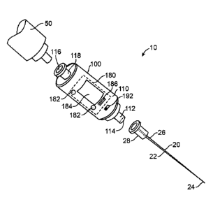
[0063] FIG. IA is a perspective illustration of an apparatus 10 for indicating
a probe tip
location or environment according to an embodiment of the disclosure. In an
embodiment, the
apparatus 10 includes a probe site indication device (PSID), probe tip
location device (PTLD), or
anatomical environment characterization device (AECD) 100 (or detection
device)that is coupled
to a probe such as a needle 20. The needle 20 includes an elongate member or
shaft 22 having a
first or insertion end or distal tip 24 and a second or proximal end 26. The
needle's shaft is
hollow, that is, the needle's elongate member includes a bore that extends
between the needle's
tip 24 and its proximal end 26. The needle's proximal end 26 can be coupled to
a conventional
needle coupling or fitting structure 28, such as a Luer adapter, connector,
sleeve, collar, or lock.
In certain embodiments, the apparatus 10 can further include a syringe 50 that
can be coupled to
the AECD 100, for instance, by way of a conventional syringe coupling or
fitting such as a Luer
adapter, connector, sleeve, collar, or lock.
100641 FIG. I B is a block diagram of an AECD 100 according to an embodiment
of the
disclosure. With simultaneous reference to FIG. 1A, in various embodiments the
AECD 100
includes a housing 110 that carries a first coupling structure 112, a first
opening or port 114, at
least one fluid or substance detection or analysis chamber or corridor 130
(e.g., a flow-through
chamber 130), a sensing unit 140, a processing unit 160, a memory 170, an
output unit 180, a'
power source 190, and an activation switch 192. In some embodiments, the
housing 110 can
additionally carry a passage 132, a second opening or port 116, and a second
coupling structure
118. Each of the sensing unit 140, the processing unit 160, the memory 170,
and the output unit
180 are coupled to the power source 190 by way of the switch 192. Selection of
a predetermined
12
Date Recue/Date Received 2023-11-27
WO 2011/022073 PCT/US2010/002305
switch position or a switch toggle can activate the AECD 100. In an
embodiment, the power
source 190 includes a battery or a capacitor configured to power the AECD 100
for a
predetermined or expected total amount of time (e.g., approximately 2 hours,
approximately 12
hours, approximately 1 day, or another amount of time).
[0065] The first coupling structure 112 carries the first port 114, and
includes one or more
coupling, fitting, securing, retaining, or connecting elements configured to
mate with a given
type of probe or needle 20. Similarly, the second coupling structure 118
carries the second port
116, and includes one or more coupling, fitting, securing, retaining, or
connecting elements
configured to mate with another medical implement such as the syringe 50. One
or both of the
first and second coupling structures 112, 118 can include or be, for instance,
a Luer adapter,
taper, collar, slip, connector, or lock structure. For instance, the first
coupling structure 112 can
include a male Luer lock fitting, and the second coupling structure 118 can
include a female Luer
lock fitting. In an embodiment, the first and second coupling structures 112,
118 are carried at
opposite sides or ends of the housing 110. Each of the first and second
coupling structures 112,
118 can carry a removable or pierceable / penetrable end cap or seal (not
shown) to facilitate the
maintenance of a controlled environment within the AECD 100.
100661 In an embodiment, the chamber 130 includes or forms a cavity or
compartment into
which a fluid or substance can flow or be drawn, and the passage 132 includes
or forms a
channel or bore through which the fluid or substance can flow or be drawn. The
chamber 130
and the passage 132 are fluid communicable or in fluid communication with the
bore of the
needle 20 by way of the first port 114. The passage 132 extends between the
first port 114 and
the second port 116, and hence the second port 116 is fluid communicable or in
fluid
communication with the bore of the needle 20 by way of the passage 132. Upon
insertion or
injection of the needle 20 into an individual's body, a bodily fluid such as
blood can flow or be
drawn from the tip 24 of the needle into the chamber 130 and the passage 132.
The bodily fluid
can further flow or be drawn through the passage 132 into the syringe 50.
[0067] The sensing unit 140 includes a set of sensors, sensing devices, or
sensing elements in
sensing communication with the chamber 130. More particularly, the sensing
unit 140 is in
signal and/or substance communication with the chamber 130, such that the set
of sensing
elements can directly or indirectly apply signals to a substance within the
chamber, detect or
measure particular properties of a substance present within the chamber,
and/or subject a
substance within the chamber to one or more tests. Particular sensing elements
may detect,
13
Date Recue/Date Received 2023-11-27
WO 2011/022073 PCT/US2010/002305
measure, or test a property of a substance within the chamber in a manner that
avoids direct
contact with the substance, while other sensing elements may detect, measure,
or test a property
of a substance within the chamber by way of direct access to or physical
contact with the
substance. The chamber 130 can include one or more openings, windows, or ports
to facilitate
.. direct access to or physical contact with a substance carried within the
chamber 130.
[0068] Particular sensors or sensing devices generate sensing signals that
correspond to one or
more physiologic properties of a substance within the chamber 130 at a
particular time.
Depending upon the nature or characteristics of a given set of sensing
signals, the set of sensing
signals may directly provide a value or measure of a physiologic parameter, or
the set of sensing
signals may be a correlate or partial correlate of the physiologic parameter.
If a set of sensing
signals provides one or more physiologic parameter correlates or partial
correlates, a number of
mathematical operations can be applied to at least a subset of signals within
the set of sensing
signals to generate, determine, or estimate at least one physiologic parameter
value.
[0069] Any given sensing device operates in accordance with a sensing device
modality, which
corresponds to a type of signal that the sensing device is configured to
acquire and/or a type of
physiologic measurement that can be generated or obtained using the sensing
signal. A
particular sensing device can operate in accordance with a modality such as
pressure sensing,
optical sensing, temperature sensing, fluid dynamics sensing, chemical or
biological species
sensing, or another modality. Depending upon embodiment details, the set of
sensors or sensing
devices can include one or more light emitting diodes (LEDs), semiconductor
lasers, optical
detectors (e.g., photodiodes, which can be configured to detect optical signal
characteristics such
as intensity, peak wavelength, or phase shift), pressure sensors (e.g., a
diaphragm and/or a
pressure transducer such as a piezoelectric transducer), temperature sensors
(e.g., an optical
temperature sensor or a thermocouple), fluid flow sensors (e.g., a Doppler
ultrasound transducer
and detector), substance or environment sensing field effect transistors
(e.g., a chemical sensing
or chemically modified FET (ChemFET), an ion sensitive FET (ISFET), an Enzyme
modified
FET (EnFET), or an electrolyte-oxide-semiconductor FET (EOSFET)), an
electrophoresis
device, a biological microchip (e.g., a biochip) or a microfluidic lab-on-a-
chip (e.g., as described
by Rohit Pal et al. in "An integrated microfluidic device for influenza and
other genetic
analyses," Lab on a chip, Royal Society of Chemistry 2005, 5, 1-9), and/or
other sensing
elements or devices.
14
Date Recue/Date Received 2023-11-27
WO 2011/022073 PCT/US2010/002305
[0070] In an embodiment directed to indicating venous versus arterial probe
access, the set of
sensing elements can include one or more devices configured to detect or
distinguish between
different physiological properties of venous versus arterial blood. More
particularly, venous
blood and arterial blood exhibit different average pressures, pulse pressure
ranges, and blood
oxygenation characteristics. In an embodiment, the set of sensing elements can
include a
pressure sensor and a blood oxygenation sensor. For instance, with respect to
sensing pressure
related parameters, the set of sensing elements can include a piezoelectric
pressure transducer
144 coupled to a diaphragm 146 that is exposed to an opening in the chamber
130. When the
chamber 130 is in fluid communication with blood sourced from a vessel,
vascular pressure
exerts a displacement force upon the diaphragm 146. The diaphragm 146 in turn
exerts a force
upon the piezoelectric pressure transducer 144, which generates an electrical
signal
corresponding to an instantaneous, quasi-instantaneous, or near-instantaneous
vessel pressure
reading at a distal probe segment or the probe tip 24.
[0071] In order to sense parameters related to blood oxygenation, the set of
sensing elements
can include a set of LEDs 150 (e.g., a visible LED and at least one infrared
LED) and a
photodetector 152. The LEDs 150 are configured to emit optical signals at or
centered about
particular wavelengths (e.g., approximately 660 nm, and one or more of
approximately 905, 910,
and 940 nm) into the chamber 130. The photodetector 152 is configured to
detect the optical
signals that are transmitted through the chamber 130, where optical signal
absorption by blood or
another substance in the chamber 130 affects the transmitted intensity of such
signals. Based
upon known oxyhemoglobin and/or deoxyhemoglobin absorbance spectra
corresponding to
particular optical wavelengths, a blood oxygenation level or state can be
determined. The LEDs
150 and the photodetector 152 in this embodiment thus form portions of an
oximeter.
[0072] The sensing unit 140 is configured to output signals (e.g., sensing
signals) to the
processing unit 160 and/or the memory 170 on a continuous or periodic basis,
and/or in response
to one or more sensed parameter values exhibiting a change that exceeds a
predetermined
magnitude relative to one or more previously sensed parameter values. With
respect to the above
described embodiment directed to indicating venous versus arterial probe
access, the sensing unit
140 can store a series of instantaneous or near-instantaneous pressure values
and/or a set of
measured optical signal values in the memory 170.
[0073] The processing unit 160 can include a state machine, a microcontroller,
a
microprocessor, an application specific integrated circuit (ASIC), or a field
programmable gate
Date Recue/Date Received 2023-11-27
WO 2011/022073 PCT/US2010/002305
array (FPGA) or programmable logic device (PLD) configured to correspond to or
execute
program instruction sequences (e.g., software and/or firmware) directed to
receiving, operating
upon, evaluating, analyzing, interpreting, and/or transforming signals
generated by one or more
portions of the sensing unit 140, and determining whether the tip 24 of the
needle 20 resides
within a target anatomical site, structure, or substance. In an embodiment,
particular program
instruction sequences can additionally or alternatively be directed to
determining whether the
needle tip 24 resides within one or more non-target, undesirable, or
inadvisable anatomical sites,
structures, or substances. Furthermore, such program instruction sequences can
be directed to
determining whether the needle tip 24 has transitioned into, resides within,
or has transitioned
away from one or more intermediary tissues or anatomical environments along a
needle insertion
trajectory toward a target anatomical destination or environment. In certain
embodiments,
particular structural portions or operational aspects of the processing unit
160 can be included or
incorporated within the sensing unit 140.
100741 In an embodiment, a given type of sensing device operates in accordance
with a
particular sensing modality and generates a particular type of sensing signal,
which depending
upon sensing device or sensing signal type can directly or by way of
mathematical correlation or
transformation provide a physiologic parameter value and hence an indication
of a probe tip
position. The processing unit 160 can use or mathematically operate upon a set
of sensing
signals corresponding to a given type of sensing device to determine a single
type of physiologic
parameter value, or multiple distinct types of physiologic values that differ
from each other by
way of a set of mathematical operations. For instance, the processing unit 160
can generate a
mean value of a physiologic parameter using a time series of sensing signals
generated by a
given type of sensing device. Additionally or alternatively, the processing
unit 160 can
additionally or alternatively generate a maximum or mean value of a
physiologic parameter
fluctuation, range, amplitude, or magnitude using this time series of sensing
signals. As a
representative example, the processing unit 160 can average a series of sensed
instantaneous
vascular pressure values to determine a mean vascular pressure value with
respect to a
predetermined time period (e.g., approximately 1 ¨ 10 seconds, 30 seconds, 1
minute, or longer).
The processing unit 160 can additionally or alternatively determine a maximum
and/or average
vascular pressure fluctuation value relative to a predetermined time period.
[0075] Different types of sensing devices can acquire sensing signals in
accordance with
different, related, or similar sensing modalities, or generate sensing signals
corresponding to
16
Date Recue/Date Received 2023-H-27
WO 2011/022073 PCT/US2010/002305
different, related, or similar types of physiologic measurements. For example,
a pressure sensor
generates signals corresponding to pressure measurements, while a chemical
species saturation
sensor generates signals corresponding to an extent to which the chemical
species is dissolved or
bound within a bodily substance. As another example, a Doppler ultrasound
device and a set of
optical emitters / detectors / other optical elements (e.g., configured to
perform Doppler or
spectroscopic measurements) can each be configured to measure or estimate
blood flow, blood
flow changes, or pulsatile aspects of vascular flow. In general, the
processing unit 160 can
mathematically operate upon sensing signals generated by single or multiple
types of sensing
devices to generate or estimate a given type of physiologic parameter value.
.. [0076] The memory 170 can include an electronically or computer
programmable or readable
medium having one or more of a Random Access Memory (RAM), a Read Only Memory
(ROM) such as a type of programmable ROM (PROM), a set of registers, or other
data storage
elements for storing a) program instruction sequences; b) signals generated or
output by the
sensing unit 140 or physiologic parameter values corresponding thereto; and c)
reference data
.. that facilitates the determination, evaluation, or analysis of sensed
physiologic parameter values.
For instance, the memory 170 can store digital absorbance spectra data that a
set of program
instructions can access to facilitate the evaluation or analysis of sensed
blood oxygenation
related parameters, and the determination of a blood oxygenation level or
state. The memory
170 can also store data (e.g., in a data structure such as a lookup table)
that a program instruction
sequence can access to a facilitate an assignment or mapping of a set of
sensed physiologic
parameter values to a categorization of the needle tip's location with respect
a target, a non-
target, and/or an intermediary anatomical structure or substance, as further
detailed below. In
association with the execution of one or more program instruction sequences,
the processing unit
160 issues or transfers reporting signals to the output unit 180 to facilitate
the provision of visual
.. and/or auditory feedback corresponding to the needle tip's sensed location.
In various
embodiments, the reporting signals can indicate whether the needle tip 24
resides at a first /
target anatomical location (e.g., by way of a first set of reporting signals),
or a second / non-
target anatomical location (e.g., by way of a second set of reporting signals
that are perceptually
different than the first set of reporting signals), as further detailed below.
In one embodiment,
the reporting signals can further indicate whether the needle tip 24 resides
at neither a first /
target anatomical location nor a second / non-target anatomical location (in
which case the
needle tip 24 may reside at an anatomical location that is unrelated to the
first / target anatomical
17
Date Recue/Date Received 2023-11-27
WO 2011/022073 PCT/US2010/002305
location and the second / non-target anatomical location). Particular aspects
of processes that
can correspond to an automated sequence (e.g., performed by way of program
instruction
execution) directed to presenting physiologic parameter values to a user
(e.g., a surgeon or other
medical professional) or observer and/or indicating a position of a probe
segment or tip 24
relative to a target, non-target, and/or intermediary anatomical site or
structure are described in
detail below with reference to FIGS. 8 - 9.
[0077] In response to the reporting signals, the output unit 180 is configured
to generate and
actively provide or convey visual and/or auditory signals that can indicate
(e.g., in a selective
manner) whether the needle tip 24 resides at or within a target or non-target
anatomical site,
structure or substance. In an embodiment, the output unit 180 actively
provides or conveys a
visual and/or auditory indication of a needle tip location by applying a non-
zero amount of
power to an output device, thereby activating the output device to selectively
emit, radiate, or
externally propagate a) a first signal that provides a user or observer with
sensory feedback
(visual and/or auditory feedback) that can indicate whether the needle tip 24
resides at a first or
target anatomical site; and b) a second signal that provides the user or
observer with sensory
feedback that can indicate whether the needle tip 24 resides at a second or
non-target anatomical
site. In one embodiment, in the event that the processing unit 160 determines
that the needle tip
24 resides at neither of a first / target anatomical location or a second /
non-target anatomical
location, the output unit 180 can be configured to avoid actively outputting
visual and/or
.. auditory signals. Alternatively, the output unit 180 can be configured to
actively output a third
signal that provides a user or observer with sensory feedback that can
indicate a neutral or
intermediary needle tip location.
[0078] Depending upon embodiment details, the reporting signals can correspond
to
notification signals and/or alert signals. Notification signals can indicate
or provide one or more
detected, measured, or estimated physiological parameter values corresponding
to sensing unit
operation. Notification signals can include, for instance, visual and/or
auditory signals
corresponding to one or more physiologic parameter values such as a blood
oxygen saturation
level, a blood pressure value, and/or a pulsatility measure or a peak-to-
minimum blood pressure
difference value. Alert signals can include visual and/or auditory signals
that provide a binary or
"yes / no" indication or a likelihood indication (e.g., a probability based
indication, as
determined in association with the execution of a program instruction
sequence) of an intended
or appropriate probe or needle positioning. In an embodiment, alert signals
can further provide a
18
Date Recue/Date Received 2023-11-27
WO 2011/022073 PCT/US2010/002305
binary or "yes / no" indication or a likelihood indication of an unintended,
undesirable, or
incorrect probe positioning.
[0079] The output unit 180 can output multiple reporting signals in a
simultaneous or non-
simultaneous (e.g., sequential) manner. Notification or alert signals can be
presented on an
essentially continuous, sampled, or periodic basis following AECD activation,
or in response to a
trigger event such as a first detection of one or more physiologic parameter
values that
correspond to a target or a non-target anatomical needle tip placement, or a
predetermined
change in a physiologic parameter value.
[0080] In general, the output unit 180 can include one or more types of output
devices, for
instance, a liquid crystal display (LCD) 182, a set of LEDs 184, and possibly
an audio device
such as a speaker 186. In an embodiment, notification signals displayed by the
LCD 182 (e.g.,
on a real-time, near real-time, a periodic basis, or in response to a given
amount of physiologic
parameter change) can include or correspond to particular physiologic
parameter values, for
instance, a hemoglobin oxygen saturation value, a blood pressure value, and/or
a pulsatility
value. The presentation of particular physiologic parameter values to a user
or observer can
facilitate the determination or confirmation of a probe tip location relative
to a target or non-
target anatomical site. In addition or as an alternative to the foregoing, the
LCD 182 can display
textual alert signals such as "venous access detected" and/or "warning ¨
arterial access detected,"
where the visual impact of one or both of such alert signals may be enhanced
by way of a visual
effect such as flashing.
[0081] The set of LEDs 184 can include a first LED 184a that is activated or
illuminated when
or while one or more sensed, estimated, or measured physiologic parameter
values indicate that
the needle tip 24 resides within a target site (e.g., a vein); and a second
LED 184b that is
activated or illuminated when or while one or more sensed, estimated, or
measured physiologic
parameter values indicate that the needle tip 24 resides within a non-target
site (e.g., an artery).
For an apparatus 10 directed to indicating or confirming successful venous
access and providing
an alert in the event of arterial access, the first LED 184a can output light
substantially having a
first color (e.g., blue or green) and possibly a first activation pattern
(e.g., continuous
illumination); and the second LED 184b can output light substantially having a
second color
(e.g., red, or another color that is visually distinguishable from the first
color) and possibly a
second activation pattern (e.g., blinking).
19
Date Recue/Date Received 2023-11-27
WO 2011/022073 PCT/US2010/002305
[0082] Finally, the speaker 186 can output a first audio alert signal such as
a tone or digital
voice signal that indicates whether the needle tip 24 is positioned at or
within a target anatomical
site. In an embodiment, the speaker 186 can additionally output a second audio
alert signal that
indicates whether the needle tip 24 is positioned at or within a non-target
anatomical site. In a
representative implementation directed to facilitating venous access and
avoiding arterial access,
the first audio signal can include a digitized voice signal that corresponds
to a phrase such as
"venous access detected," and the second audio signal can include a digitized
voice signal that
corresponds to a phrase such as "warning ¨ arterial access detected." In
another embodiment,
the speaker 186 can output one or more audio notification signals that
correspond to or indicate
the values of sensed, estimated, or measured physiologic parameters (for
instance, the speaker
186 can output audio signals corresponding to internal bodily sounds, pressure
waves, or
pressure changes).
[0083] In view of the foregoing, in an embodiment the apparatus 10 can
differentially
communicate or convey by way of output device activation one or more
indications of probe tip
or distal segment position relative to a target and/or a set of non-target
anatomical sites,
structures, or substances. In such an embodiment, the output unit 180 can
include a) at least one
output device capable of providing at least a two-state active indication of
reporting signal values
or probe tip positions with respect to the target and non-target anatomical
sites; or b) multiple
output devices, each of which is capable of providing at least a single-state
active indication of a
reporting signal value or a probe tip position with respect to the target or
non-target anatomical
sites.
[0084] In a representative embodiment, a display device can provide a two-
state active
indication of two reporting signal values by way of two displayed values. An
audio device can
provide a two-state active indication of two reporting signal values by way of
two types of audio
tones or messages. Additionally, a multi-color LED or a mutli-color LED array
can provide a
two-state active indication of two reporting signal values by way of
outputting light of different
colors that can be readily distinguished by the human eye.
[0085] FIG. 1C is a block diagram of an AECD 102 according to another
embodiment of the
disclosure, in which the AECD 102 is configured to communicate with a remote
or external
device such as a computer system 90 (e.g., a desktop computer, a laptop
computer, or a personal
digital assistant) or a given piece of medical equipment 92. In the embodiment
shown, in
addition to including the elements described above with respect to FIG. 1B,
the AECD 102
Date Recue/Date Received 2023-H-27
WO 2011/022073 PCT/US2010/002305
includes a communication unit 185 that is coupled to the memory 170, the
processing unit 180,
and the switch 192, which selectively couples the AECD 102 to the power source
190. The
communication unit 185 can further be coupled to the sensing unit 140. The
communication unit
185 can be configured for wireless or wire-based signal transfer involving the
remote computer
system 90 or medical device 92, such as an ultrasound system or device (e.g.,
portable ultrasound
unit), and the like. In a representative implementation, the communication
unit 185 includes a
radio frequency (RF) communication circuit.
[0086] Thus, in certain embodiments, a sensing device of the present
invention, including
those described herein, may be operable in communication with another separate
or remote
device, including output of data to the remote device, uploading or receiving
data from the
remote device, or both outputting and receiving data. Output of data from a
device of the present
invention to a remote device may be selected, for example, for visual display
of data from the
sensing device on the remote device display or screen. Data from a remote
device may, in
certain instances, be received by a sensing device of the present invention,
and data from the
remote device optionally being displayed on the sensing device.
[0087] By way of the communication unit 185, the AECD 102 can transfer a
sequence of
physiologic or physiologic correlate parameter values to one or more remote
systems or devices
90, 92. Additionally or alternatively, the communication unit 185 can transfer
reporting signals
or notification and/or alert signals to a remote system or device 90, 92. One
or more of
physiologic or physiologic correlate parameter values, reporting signals,
notification signals, and
alert signals can reside in the memory 170 to facilitate such transfer. Signal
transfer between the
AECD 102 and a remote system or device 90, 92 can occur on a real time, near-
real time,
periodic, event triggered, or command-response basis while the AECD 102 is
active. In an
embodiment, signal transfer to a remote system or device 90, 92 can be
initiated or triggered in
response to the detection (e.g., optical detection) of blood or another bodily
fluid in the chamber
130. Additionally or alternatively, signal transfer from the AECD 102 to the
remote system or
device 90, 92 can include a medical procedure data upload process involving
the transfer of
physiologic or physiologic correlate parameter values, reporting signals,
notification signals,
and/or alert signals that the sensing and/or processing units 140, 160 had
stored or recorded in
the memory 170 during or throughout one or more time intervals corresponding
to a medical
procedure (e.g., during a 15 or a 30 minute period following AECD activation /
chamber fluid
detection in association with a CVC placement procedure). Furthermore, in an
embodiment the
21
Date Recue/Date Received 2023-11-27
WO 2011/022073 PCT/US2010/002305
communication unit 185 can download or receive AECD configuration data or
program
instruction sets from a remote computer system 90 to the memory 170, such that
the AECD 102
can be programmably reconfigured (e.g., by way of a transfer of a firmware
update, a program
instruction sequence, or a programmable logic configuration bitstream) on an
as-needed basis
(e.g., in view of a given medical indication).
[0088] In an embodiment, the sensing unit 140 and/or the processing unit 160
can store or
record measured or sampled pressure and/or other physiologic parameter values
in the memory
170 on an essentially continuous or sampled basis (e.g., approximately every
0,5 ¨ 500
milliseconds, or approximately every 2.5 - 250 milliseconds, or approximately
every 5, 10, 50, or
100 milliseconds) or at predetermined time intervals. The communication unit
185 can transfer
stored pressure values to a remote device 92 that is configured to receive the
individual pressure
values and display and/or analyze a corresponding pressure waveform (e.g., a
vascular pressure
waveform). Such transfer can occur on an essentially real time or near-real
time basis, or a
delayed basis.
[0089] FIG. 2A is a perspective illustration of an apparatus 12 for indicating
a probe segment
or probe tip location according to another embodiment of the disclosure. In an
embodiment, the
apparatus includes a probe or needle 20 that is coupled to an AECD 104 having
at least one
auxiliary, adjunctive, subsidiary, or supplementary access structure, member,
or shaft 120. The
auxiliary access structure 120 includes an auxiliary access port 122
configured for fluid
communication with the AECD's passage 132. In an embodiment, the auxiliary
access port 122
resides at a distal portion or end of a channel 124 carried by the auxiliary
access structure 120. A
proximal portion or end of the channel 124 is coupled to the AECD's passage
132 by way of an
opening, such that the auxiliary access port 122 is fluid communicable or in
fluid communication
with the passage 132. The auxiliary access structure 120 can extend at a
predetermined angle
(e.g., approximately 45 degrees) away from a surface or side of the AECD 104.
In general, the
auxiliary access structure 120 is offset from an AECD surface or side that
carries the output unit
180.
[0090] The auxiliary access port 122 facilitates the insertion of one or more
types of auxiliary
or adjunctive devices into the passage 132 of the AECD 104, and possibly
through the AECD
104 and into or through the bore of the needle 20. An auxiliary device can
include, for instance,
a guidewire 60 or a sensing device that carries a set of sensing elements
configured for insertion
into a patient's body. The auxiliary access structure 120 can carry a
removable or pierceable /
22
Date Recue/Date Received 2023-11-27
WO 2011/022073 PCT/US2010/002305
penetrable end cap or seal (not shown) that prevents the exposure of a fluid
present within the
AECD 104 to an external environment until the seal is removed or pierced.
Additionally, the
auxiliary access structure 120 can include a set of dynamic sealing elements
128 such as one or
more o-rings (e.g., located or seated at a distal segment or end of the
auxiliary access structure
120) that facilitate the maintenance of a leak proof or leak resistant seal
around the periphery of
an auxiliary access device after auxiliary access device insertion. The
presence of a dynamic
sealing element 128 can ensure that sensed blood pressure values remain
accurate or consistent
after an auxiliary access device such as a guidewire 60 resides within a
portion of the AECD
104.
[0091] Depending upon embodiment details, the auxiliary access structure 120
can carry or
include one or more types of structural elements that facilitate the
maintenance of pressure
integrity within the AECD 104 following insertion of a guidewire or other
device (e.g., a set of
optical fibers) into the auxiliary access port 122 and the auxiliary access
structure's channel 124.
Particular types of structural elements that facilitate the maintenance of a
seal around a guidewire
or other device are described in detail hereafter.
100921 FIG. 2B is a cross sectional illustration of a webbed o-ring structure
1000, and FIG. 2C
is a cross sectional illustration of the webbed o-ring structure 1000 in a
sealing configuration
around a guidewire 60 according to an embodiment of the disclosure. In an
embodiment, the
webbed o-ring structure 1000 includes an o-ring 1002 that carries a resilient,
pierceable web or
membrane 1010 that spans an inner diameter d, of the o-ring 1002. Upon
guidewire insertion
through the membrane 1010, a portion of the membrane 1010 surrounding the
guidewire 60
dynamically conforms to the guidewire's periphery, thereby establishing a
continuous seal
between the guidewire 60 and the membrane 1010. In a representative
implementation, each of
the o-ring and the membrane 1010 can be made using Silicone.
[0093] FIG. 2D is a cross sectional illustration of a flexible seal structure
1050 according to an
embodiment of the disclosure. In an embodiment, the flexible seal structure
1050 includes a
plurality of pierceable seal elements 1052 carried at, proximate to, or along
an insertion end of
the auxiliary access structure 120. Each seal element 1052 comprises a
pierceable and resilient
or flexible material, which can include for instance, Silicone. On an
individual basis, upon
guidewire insertion, a portion of each any given seal element 1052 surrounding
the guidewire 60
dynamically conforms to the guidewire's periphery. Thus, following guidewire
insertion
23
Date Recue/Date Received 2023-11-27
WO 2011/022073 PCT/US2010/002305
through the plurality of seal elements 1052, the plurality of seal elements
1052 form a composite
seal that facilitates the maintenance of intra-AECD environmental integrity.
[0094] FIG. 2E is a cross sectional illustration of a securable or lockable
sealing structure 1080
in a loose configuration around a guidewire 60, and FIG. 2F is a cross
sectional illustration of a
lockable sealing structure 1080 in a sealing configuration around a guidewire
60 according to an
embodiment of the disclosure. In an embodiment, the lockable sealing structure
1080 includes
an o-ring 1082 carried by a portion of the auxiliary access structure 120
proximate to the
auxiliary access port, and a knob 1084 that matingly fits into the auxiliary
access port 122. The
knob 1084 includes an opening or channel 1086 therethrough, which is
dimensioned to
accommodate the periphery of a guidewire 60 or other device.
[0095] An external portion of the knob 1084 and an internal portion of the
auxiliary access port
122 can carry counterpart thread elements that facilitate screw-type insertion
and selectable
locking (e.g., by hand or use of a knob adjustment tool) of the knob 1084 in
the auxiliary access
port 122. When the knob 1084 remains in a first or unlocked position, the o-
ring 1082 is
uncompressed. A guidewire 60 extending through the knob's channel 1086 can
therefore
slidably move into and along the length of the auxiliary access structure's
channel 124 with
minimal, negligible, or no friction resulting from o-ring contact with the
guidewire 60. Turning
the knob 1084 to a second or locked position compresses the o-ring 1082,
thereby decreasing the
0-ring's inner diameter such that the a-ring 1082 abuts and surrounds the
periphery of the
guidewire 60 and forms a seal around the guidewire 60. Transitioning the knob
1084 to a locked
position can correspondingly lock the guidewire 60 in place.
[0096] FIG. 2G is a perspective illustration of an apparatus 14 for indicating
a probe segment
or probe tip location according to a further embodiment of the disclosure. The
apparatus 14
includes a probe or needle 20; an AECD 104 having an auxiliary access port
122; and possibly a
syringe 50. In an embodiment, the apparatus 14 additionally includes a
guidewire 60 and a
guidewire retention device 70. In general, the guidewire retention device 70
includes a set of
receiving structures that can releasably carry portions of the AECD 104, and
which can restrain,
grasp, capture, or clamp the guidewire 60 following AECD removal from the
guidewire retention
device 70, as further detailed below. The guidewire retention device 70
facilitates the
withdrawal of the AECD 104 and the needle 20 from the guidewire 60 as an
integral unit or
separate units in association with the capture of the guidewire 60 at or along
a given portion of
the guidewire's length.
24
Date Recue/Date Received 2023-H-27
WO 2011/022073 PCT/US2010/002305
[0097] The guidewire retention device 70 can include a first receiving portion
72a and a
second receiving portion 72b that are pivotally coupled at or about a first
and a second hinge
point by a first and a second hinge member 74a, 74b, respectively, one or both
of which are
resiliently releasable and/or positionally lockable. The guidewire retention
device 70 includes a
.. capture end 76 and a receiving end 78. In an embodiment, one or both hinge
members 74a, 74b
can include a biasing element such as a spring that maintains the guidewire
retention device 70 in
a capture position in which the first and second receiving portions 72a, 72b
are retained in close
or generally close proximity to each other at the guidewire retention device's
capture end 76,
such that a separation or gap between the first and second receiving portions
72a, 72b is slightly
less than the diameter of the guidewire 60.
[0098] The AECD 104 can be inserted into the guidewire retention device's
receiving end 78,
and the first and second receiving portions 72a, 72b can be positioned or
secured around portions
of the AECD's periphery, thereby maintaining the guidewire retention device 70
in a carry
position. One or both of the first and second receiving portions 72a, 72b can
include a contoured
inner surface that facilitates the automatic or semi-automatic closure of the
first and/or second
receiving portions 72a, 72b around a portion of the AECD's periphery in
response to insertion of
the AECD 104 into the guidewire retention device 70. While in the carry
position, the first and
second receiving portions 72a, 72b are separated from each other at the
guidewire retention
device's a) receiving end 78 by a distance corresponding to the external or
exterior profile of the
AECD 104; and b) capture end 76 by a distance that exceeds the diameter of the
guidewire 60
and which facilitates unhindered or generally unobstructed coupling of the
needle 20 to the
AECD's first coupling structure 112.
[0099] In association with a representative medical procedure, the guidewire
retention device
70 can initially hold or carry the AECD 104, and the needle's coupling
structure 28 can be fated
to the AECD's first coupling structure 112. Following the injection of the
needle 20 into a
patient's body and a determination that the tip 24 of the needle 20 resides at
or within a target
anatomical location (e.g., a vascular structure such as the left internal
jugular vein) in accordance
with an embodiment of the disclosure, a guidewire 60 can be inserted into and
through the
AECD 104 and the needle 20, such that a portion of the guidewire resides at or
within the target
.. anatomical location. The AECD 104 and the needle 20 can subsequently be
withdrawn from the
guidewire 60, for instance, by a force that pulls the AECD 104 and the needle
20 away from the
patient's body while the guidewire retention device 70 is held in a stationary
or generally
Date Recue/Date Received 2023-H-27
WO 2011/022073 PCT/US2010/002305
stationary position. Upon removal of the AECD 104 and the needle 20 from the
guidewire
retention device 70, the guidewire retention device 70 can resiliently or
automatically transition
to the retaining position, such that the first and second receiving portions
72a, 72b grasp or
restrain the guidewire 60 at the guidewire retention device's capture end 76.
[0100] FIG. 3 is a perspective illustration of an apparatus 16 for indicating
a probe segment or
probe tip location according to another embodiment of the disclosure. In an
embodiment, the
apparatus 16 includes a probe or needle 20; an AECD 104, which may have an
auxiliary access
port 122; and possibly a syringe 50. In an embodiment, the apparatus 14
additionally includes a
movable or repositionable dilator or dilator assembly 80 that is coupled to
the AECD 104, and
which in a particular embodiment is coupled to the AECD 104 in a removable,
releasable, or
detachable manner. In general, the repositionable dilator 80 includes a
support arm 82 that
carries a dilating member 84, a first positioning member 85, and a release
element 88. The
AECD 104 can carry a second positioning member 86 that matingly fits into or
receives the first
positioning member 85 in a manner that facilitates adjustable or slidable
movement of the dilator
80 relative to the AECD 104 along a direction or axis that is parallel to the
bore of the needle 20.
In a representative implementation, the first positioning member 85 can
include a receiving
structure having a groove or slot, and the second positioning member 86 can
include a spine
configured for insertion into the slot and progressive displacement along the
slot's length. The
dilator 80 can additionally carry a position control element 89 such as a
lever or knob.
[0101] The dilating member 84 includes a tapered hollow enclosure having a
predetermined
largest diameter at a proximal end, a predetermined smallest diameter at a
distal end, and a
progressive diameter taper between its proximal end and distal end. The
predetermined smallest
diameter is slightly larger than the diameter of the needle. The dilator 80
can receive the AECD
104 and the needle 20 as an integral unit. More particularly, the AECD 104 and
a needle 20
coupled thereto can be mounted to the dilator 80 such that the first
positioning member 85
resides along a portion of a side or surface of the AECD 104 that carries the
second positioning
member 86, and the dilating member 84 surrounds a portion of the needle's
shaft 22.
101021 The position control element 89 can be a knob or lever that facilitates
the translation of
the dilator support arm 82 and hence the translation of the dilating member 84
along the needle's
shaft 22. A surgeon can advance the dilating member 84 along the shaft 22 of
the needle 20 and
into the patient's tissue at a needle tip entry site. The release element 88
can release or detach
the second positioning member 86 carried by the AECD 104 from the dilator's
first positioning
26
Date Recue/Date Received 2023-11-27
WO 2011/022073 PCT/US2010/002305
member 85, such that the needle 20 can be withdrawn from the patient's body
and the dilating
member 84.
(01031 In certain embodiments, one or more elements or devices that facilitate
sensing
operations can be carried or inserted within a patient's body. More
particularly, a set of sensing
elements or devices can be advanced into, carried by, or advanced through the
shaft 22 of a
needle or probe 20, such that particular types of signals and/or substances
can be detected within
the probe 20; at or proximate to the probe's tip 24; or at a location beyond
the probe's tip within
the patient's body. Sensing elements or devices suitable for internal bodily
use can include one
or more of optical fibers, optical detectors, ultrasonic transducers,
ultrasound detectors, electrical
leads, electrical sensors, pressure sensors, chemical sensors, and/or other
devices. Portions of an
AECD 100, 102, 104 can be configured to accommodate and/or interoperate with
internal bodily
sensing elements or devices, as further detailed hereafter.
[01041 FIG. 4A is a perspective illustration of a probe 200 carrying a set of
sensing elements
210 according to an embodiment of the disclosure. The set of sensing elements
210 can include,
for instance, one or more optical fibers, optical emission or detection
devices, electrical leads,
electrodes or electrical contacts, pressure sensors, ultrasonic transducers or
ultrasound detectors,
biological or chemical substance sensors, or other elements. In an embodiment,
the probe 200
includes a shaft 202 having a distal segment or tip 204, and a proximal end
206 that is coupled to
a probe sensing fitting 208. The probe sensing fitting 208 can include a Luer
or other type of
adapter, connector, sleeve, collar, or lock that carries, surrounds, or
encapsulates a portion of the
set of sensing elements. The probe sensing fitting 208 can include or
correspond to, for instance,
a female Luer lock fitting.
[0105] At least a portion of the set of sensing elements 210 is carried by the
probe's shaft 202.
The set of sensing elements 210 is coupled to the probe sensing fitting 208 in
a manner that
facilitates sensed signal communication with the AECD 100, 102, 104, as
further detailed below
with reference to FIG. 4B.
[0106] The set of sensing elements 210 can include a set of signal interface
elements or
structures 228 that are carried by the probe sensing fitting 208 to facilitate
signal communication
with the AECD 100, 102, 104. For instance, the set of signal interface
elements 228 can include
one or more of an optical fiber interfaces or lens, or an electrical contact
or pin. Such signal
interface elements 228 can reside at predetermined positions relative to the
probe sensing fitting
27
Date Recue/Date Received 2023-H-27
WO 2011/022073 PCT/US2010/002305
208, and mate with a particular portion of the AECD 100, 102, 104 in a
specified manner to
facilitate reliable signal communication.
101071 In an embodiment, the probe's shaft 24 can be substantially or
completely obstructed to
prevent fluid communication between the probe's tip 204 and proximal end 206.
In another
embodiment, the probe's shaft 202 can include a conduit therethrough to
facilitate such fluid
communication. In an embodiment in which the probe's shaft is substantially
hollow or includes
a conduit, a bodily fluid can flow or be drawn into the AECD 100, 102, 104 for
sensing or
analysis, and/or into a syringe 50 that is coupled to the AECD 100, 102, 104.
[0108] FIG. 4B is a perspective illustration of an AECD sensing fitting 320
configured for
.. signal communication with a probe sensing fitting 208 according to an
embodiment of the
disclosure. In an embodiment, the AECD sensing fitting 320 includes one or
more coupling,
fitting, securing, retaining, or connecting structures that carry set of
signal interface elements
322. Such coupling structures can include a Luer or other type of adapter,
taper, collar, slip,
connector, or lock structure. For instance, the AECD sensing fitting 320 can
include or
correspond to a male Luer lock structure.
[0109] The signal interface elements 322 carried by the AECD sensing fitting
320 are
configured to structurally mate with and functionally correspond to the signal
interface elements
228 carried by the probe sensing fitting 208. Thus, the signal interface
elements 322 carried by
the AECD sensing fitting 320 and the signal interface elements 228 carried by
the probe sensing
fitting 208 are structural and functional counterparts that facilitate
consistently reliable error free
signal transfer between the set of sensing elements 210 carried by the probe
200 and the AECD
100, 102, 104.
[0110] In addition to the foregoing, certain devices or elements that
facilitate sensing
operations and which are inserted into and carried within a patient's body can
be coupled to a
.. remote or external device 90, 92, such that they extend from a location
within the patient's body
into and through the AECD 100, 102, 104 to the remote or external device 90,
92, e.g., by way of
the AECD's auxiliary access port 122. Such devices or elements can include,
for instance,
optical fibers, electrical leads, or guidewires that carry sensing elements,
as further detailed
below with reference to FIGS. 5A ¨ 5B.
[0111] FIG. 5A is a perspective illustration of a probe or needle 20 carrying
a set of sensing
elements 300 according to an embodiment of the disclosure. Such sensing
elements 300 can
28
Date Recue/Date Received 2023-11-27
WO 2011/022073 PCT/US2010/002305
include, for instance, one or more optical fibers and/or electrical leads that
extend through the
probe or needle 20, depending upon embodiment details. Such sensing elements
300 can further
include one or more distal signal transfer elements or devices 310. For
instance, distal signal
transfer devices 310 in an embodiment involving optical fibers can include one
or more lenses,
diffraction gratings, or other optical elements positioned at, proximate to,
or beyond the tip 24 of
the probe or needle 20. In an.embodiment involving electrical leads, distal
signal transfer
devices 310 can include particular types of electrical, biological, or
chemical sensing elements
(e.g., an electrical sensor, a pressure transducer, or an ultrasonic
transducer) carried at, proximate
to, or beyond the probe's tip 24. A given optical fiber, optical element,
electrical lead, and/or
sensing element can be retained or secured at a predetermined position within
the probe or
needle 20 (e.g., proximate to the probe's tip 24 and/or proximate to the
probe's coupling
structure 28). In general, a group of optical fibers and/or electrical leads
can be coupled or
bundled to facilitate ease of insertion into an AECD's auxiliary access port
122, through the
AECD 100, 102, 104, and into the probe or needle 20. A remote or external end
of the set of
optical fibers and/or electrical leads can be coupled to a remote or external
computer system or
medical device 90, 92.
[0112] FIG. 5B is a perspective illustration of a needle carrying a sensing
guidewire 400
according to an embodiment of the disclosure. In an embodiment, the sensing
guidewire 400 can
carry, for instance, a set of optical fibers and/or electrical leads 410, as
well as a corresponding
set of optical elements and/or sensing devices 412 at a terminal or distal
segment or end of the
optical fibers or electrical leads, respectively. A sensing guidewire 400 can
be inserted into and
through an AECD 100, 102, 104 and into a probe or needle 20 in a manner
previously described.
A remote or external end of the sensing guidewire 400 can be coupled to a
remote or external
computer system or medical device 90, 92.
[0113] Aspects of Representative Integral Embodiments
[0114] In certain embodiments, one or more portions of an apparatus or device
for indicating
or verifying a probe tip location can be integrally carried by portions of a
probe, a syringe, or
another apparatus or device. In the description that follows, the recitation
of a reference number
that is identical or analogous to a reference number recited in relation to
one or more of FIGS.
lA ¨ 5B indicates an element that is identical or analogous that previously
described.
[0115] FIG. 6A is a perspective illustration of a representative AECD needle
assembly or
needle AECD 500 according to an embodiment of the disclosure. In an
embodiment, the needle
29
Date Recue/Date Received 2023-H-27
WO 2011/022073 PCT/US2010/002305
AECD 500 includes a needle portion 520 that is integrally coupled to an AECD
portion 510.
The needle portion includes a shaft 522 and a distal end or tip 524. A
coupling structure 528
such as a Luer type fitting, which can facilitate coupling to a syringe 50,
can be carried by the
AECD portion 510. The needle portion 520 includes a bore or conduit
therethrough, which
extends between the tip 524 and the coupling structure 528. In an embodiment,
a section of the
needle portion's bore forms a passage 532 within the AECD portion 510.
[0116] The AECD portion 510 internally carries a sensing unit 140, a
processing unit 160, a
memory 170, and a power source 190, in a manner analogous to that described
above with
reference to FIGS. 1B and 1C. One or more of the sensing unit 140, the
processing unit 160, and
the memory 170 can be coupled to an output unit 180 that includes a set of
output devices or
elements such as an LCD display 182, a set of LEDs 184, and/or an audio device
186. The LCD
display 182 and the set of LEDs 184 can be carried in a manner that
respectively facilitates the
transmission or propagation of visual LCD and LED signals generated thereby
external to the
needle AECD 500. Similarly, the audio device 186 can be carried by the needle
AECD 500 in a
manner that facilitates the transmission or propagation of audio signals
generated thereby
external to the needle AECD 500. An activation switch 192 can selectively
couple the sensing
unit 140, the processing unit 160, the memory 170, and the output unit 180 to
the power source
190.
[0117] FIG. 6B is a perspective illustration of a representative AECD syringe
assembly or
syringe AECD 550 according to an embodiment of the disclosure. In an
embodiment, the
syringe AECD 550 includes a syringe portion 560 having a hollow or generally
unobstructed
shaft 562 in which a plunging element 565 can travel or reside. The shaft 562
includes a distal
portion or end 564 that carries a coupling or fitting structure 568, such as a
Luer type fitting,
which can facilitate coupling to a needle 20. The shaft 562 of the syringe
portion 560 integrally
carries an AECD portion 580 that is configured in a manner that is identical
or similar to that
described above for the needle AECD 500.
[0118] FIG. 6C is a perspective illustration of a line-based AECD assembly or
an in-line
AECD 600 according to an embodiment of the disclosure. In an embodiment, the
in-line AECD
600 includes an AECD portion 610 that is structurally and/or functionally
analogous to one or
more AECD embodiments 100, 102, 104, 500, 510 described above, but which is
detachably or
nondetachably coupled to a flexible or rigid first tube or line 620 and/or a
second line 625. The
first tube or line 620 can be coupled to a needle 20, and the second line 625
can be coupled to a
Date Recue/Date Received 2023-11-27
WO 2011/022073 PCT/US2010/002305
line fitting or coupling (e.g., a Luer type fitting) 628. A bodily fluid can
flow between the needle
tip 24, the first tube or line 620, and the second line 625 by way of passing
through the AECD
portion 610. In an embodiment, the first tube or line 620 can be omitted, such
that the AECD
portion 610 is directly coupled to the needle 20.
[0119] Aspects of Representative Probe Location Indication Processes
[0120] Relative to a physiologic parameter of interest, a given patient
population can exhibit a
range of physiologic parameter values, particularly when different patient
subpopulations are
considered, such as typical, normal, or healthy patients as well as less
typical, abnormal, or
health-impaired patients. For instance, particular physiologic parameter value
ranges that can be
relevant to a vascular access procedure are shown below with reference to
Tables 1 ¨3; and
certain physiologic parameter value ranges that can be relevant to a lumbar
puncture procedure
are shown below with reference to Table 4.
[0121] Table 1 illustrates representative venous and arterial blood pressure
ranges associated
with patient states corresponding to low blood pressure conditions, normal
blood pressure
conditions, and high blood pressure conditions.
Vessel Type Low Pressure Normal Pressure High
Pressure
Vein <5 mm Hg 5,25 mmHg 25-40 mmHg
Artery 45-55 mm Hg 55-160 mm Hg 160-
225 mm Hg
Table 1: Expected Venous versus Arterial Pressure Conditions
[0122] Table 2 illustrates representative venous and arterial pulse pressure
variations, that is,
typical or expected peak-to-minimum pulse pressure differences corresponding
to veins and
arteries.
Vessel Type Pulse Pressure
Variation
Vein 2-10 mm Hg
31
Date Recue/Date Received 2023-H-27
WO 2011/022073 PCT/US2010/002305
Artery >20 mm Hg (30-70mm Hg)
Table 2: Expected Venous versus Arterial Pulse Pressure Variation
[0123] Table 3 illustrates representative venous and arterial hemoglobin
oxygen saturation
value ranges corresponding to low, normal, and high patient hemoglobin oxygen
saturation
conditions.
Vessel Type Low Hemoglobin Normal Hb High Hb Saturation
Saturation Saturation
Vein 10-40% 40-60% >60%
Artery 85-92% 92-100% N/A
Table 3: Expected Venous versus Arterial Hemoglobin Saturation Conditions
[0124] Table 4 illustrates representative values or value ranges of
cerebrospinal fluid
parameters that can be relevant to a lumbar puncture procedure for particular
patient populations,
including low, normal, and high parameter values corresponding to penetration
pressure, protein
concentration, glucose concentration, red blood cell concentration, and white
blood cell
concentration.
Parameter Low Value Normal Value High Value
Opening Pressure <10 mm 1120 10-100 mm 1120 >100 MM 1120
(child)
Opening pressure <60 mm H20 60 -250 (obese) mm >
250 mm H20
(adult) H20
32
Date Recue/Date Received 2023-H-27
WO 2011/022073 PCT/US2010/002305
Protein (newborn) N/A <1.5 g/L > 1.5 g/L
Protein (adult) <0.18 g/L 0.18-0.58 g/L >0.6 g/L
Red Blood Cells N/A None
Glucose N/A 2/3 serum > 300 mg/dL
glucose
White Blood Cells N/A., 5-20 cells/ mm3 > 100 cells/
MM3
Table 4: Particular Expected Low, Normal, and High Parameter Values Relevant
to Lumbar
Puncture Procedures
[0125] As a result of physiologic parameter variations such as those indicated
in Tables 1 - 3
or Table 4 above, one or more reference or threshold physiologic parameter
values or value
ranges corresponding to target anatomical structures or substances, non-target
anatomical
structures or substances, and/or patient state conditions or categorizations
can be stored in a
portion of the memory 170 (e.g., in a data structure such as a table) that a
program instruction
sequence can access. For instance, FIG. 7 is a block diagram of a
representative data structure or
table 700 that stores data or values corresponding to a venous blood pressure
threshold, an
arterial blood pressure threshold, a venous hemoglobin saturation threshold,
and an arterial
hemoglobin saturation threshold according to an embodiment of the disclosure.
In an
embodiment, the data structure or table 700 can additionally store a venous
pulse pressure
variation threshold and an arterial pulse pressure variation threshold.
Particular data values
within the data structure or table 700 can reside in the memory 170.
[01.261 A given reference physiologic parameter value or value range can
respectively
represent a value transition level or value interval that facilitates a
categorization or mapping of a
non-reference physiologic parameter value in accordance with an anatomical
environment,
tissue, or substance type, where the non-reference physiologic parameter value
was sensed,
33
Date Recue/Date Received 2023-H-27
WO 2011/022073 PCT/US2(i10/002305
measured, calculated, or estimated using one or more sets of sensing signals
generated by the
sensing unit 140. In an embodiment, if a non-reference sensed physiologic
parameter value is
below an upper reference physiologic parameter limit, above a lower reference
physiologic
parameter limit, or within a reference physiologic parameter value range
corresponding to or
.. indicative of a given type of anatomical environment, the non-reference
sensed physiologic
parameter can be defined as corresponding to or indicative of the anatomical
environment.
[0127] A program instruction sequence can evaluate or analyze a set of sensed
parameter
values at one or more times relative to at least a subset of reference
physiologic parameter values
or value ranges, after which an output unit 180 can present a number of
notification and/or alert
signals that indicate or convey a) a type of environment, tissue, or substance
in which the needle
tip 24 presently resides (e.g., a target anatomical environment, or a non-
target anatomical
environment); b) a likelihood of whether the needle tip 24 remains positioned
at or within a
target or a non-target environment, tissue, or substance during portions of a
medical procedure;
and/or b) patient state information. Representative processes for determining
a probe tip position
.. and/or patient state information and providing corresponding notification
or alert signals are
described in detail hereafter with reference to FIGS. 8 ¨ 9.
[0128] FIG. 8 is a flow diagram of a process 800 for indicating probe or
needle tip positioning
relative to a target vascular structure or substance according to an
embodiment of the disclosure.
Particular portions of the process 800 can be performed, for instance, by way
of a processing
unit's execution of program instructions. In an embodiment, the process 800
includes a first
process portion 810 that involves coupling an AECD 100, 102, 104 to a probe or
needle 20, and
possibly coupling the AECD 100, 102, 104 to a syringe 50. A second process
portion 812
involves activating the AECD 100, 102, 104 (e.g., by way of the activation
switch 192), and a
third process portion 814 that involves inserting the probe or needle 20 into
the patient's tissue.
[0129] The process 800 further includes a fourth process portion 820 that
involves detecting
the presence of a bodily substance or fluid within the AECD's chamber 130, for
instance, by
detecting a change in an optical signal and/or a chamber pressure transition
(e.g., by way of a
photodetector 152 and/or a piezoelectric transducer 144) that results from a
bodily fluid flowing
or being drawn from the probe or needle tip 24 through the bore of the probe
or needle 20 and
into the chamber 130. The process 800 also includes a fifth process portion
830 that involves
sensing, detecting, measuring, determining, or estimating a set of physiologic
or physiologic
correlate parameters corresponding to the fluid in the chamber 130, for
instance, one or more of
34
Date Recue/Date Received 2023-11-27
WO 2011/022073 PCT/US2010/002305
an instantaneous or average fluid pressure, a maximum fluid pressure variation
or range, and a
set of optical parameters that are correlated with a hemoglobin oxygenation
state.
[0130] A sixth process portion 840 involves characterizing, evaluating, or
analyzing the set of
sensed or measured physiologic parameter values corresponding to the fluid
within the chamber
130. In an embodiment, the sixth process portion 840 can involve a
transformation or
conversion of particular sensed physiologic parameter correlate values to a
measure or estimate
of a value for a physiologic parameter. For instance, the sixth process
portion 840 can involve a
determination or estimation of an oxygenation, deoxygenation, or other gas
saturation state based
upon sensed or measured optical signals in view of reference optical
absorbance spectra data. In
an embodiment, the sixth process portion 840 further involves a comparison of
sensed or
measured parameter values relative to one or more reference or threshold
physiologic parameter
values stored in a memory 170 (e.g., within a data structure 700) to
facilitate discrimination
between venous and arterial blood, and hence discrimination between a probe or
needle tip
positioning within a vein or an artery. For instance, if the sensed or
measured parameter values
indicate an average pressure of less than approximately 40 mmHg, a pressure
variation of less
than approximately 15 mmHg, and a hemoglobin oxygen saturation of less than
approximately
60%, the sixth process portion 840 can determine that the probe or needle tip
24 resides in a vein.
If the sensed or measured parameter values indicate an average pressure of
greater than
approximately 45 mmHg, a pressure variation of greater than approximately 20
mmHg, and a
hemoglobin oxygen saturation of greater than approximately 80%, the sixth
process portion 840
can determine that the probe or needle tip 24 resides in an artery.
[0131] In an embodiment, if a comparison, evaluation, or analysis of one or
more sensed or
measured parameters relative to a set of reference parameter values gives rise
to uncertainty in a
tissue or fluid type determination, the sixth process portion 840 can generate
a likelihood or
confidence value corresponding to the tissue or fluid type determination. Such
a likelihood or
confidence value can be included in a set of reporting signals for subsequent
presentation or
display (e.g., as a notification signal) to a surgeon or other medical
professional.
[0132] A seventh process portion 850 involves generating and transferring or
issuing reporting
signals to an output unit 180, where the reporting signals can correspond to
or include
notification and/or alert signals. An eighth process portion 860 involves the
presentation of
notification and/or alert signals using one or more output devices, for
instance, in one or more
manners previously described. By way of the eighth process portion 860, a) an
LCD 182 or
Date Recue/Date Received 2023-11-27
WO 2011/022073 PCT/US2010/002305
other display device can present or output sensed, measured, or estimated
physiologic parameter
values; and/or b) a set of LEDs 184 or an audio device 186 can be activated to
indicate that the
tip 24 of the probe or needle 20 resides in a target or non-target type of
bodily tissue or fluid. In
an embodiment, a confidence value can be indicated by the LCD 182 or the set
of LEDs 184.
10133] A ninth process portion 870 involves repeating the fifth through eighth
process portions
830 ¨ 860 such that updated notification and/or alert signals can be presented
on a continuous or
periodic basis. The ninth process portion 870 can facilitate a determination
of whether the probe
or needle tip 24 remains in a target or intended type of bodily tissue or
fluid, or has moved into a
non-target or unintended type of bodily tissue or fluid.
[0134] A tenth process portion 880 involves determining whether the needle 20
is correctly
positioned or located in a target or intended bodily tissue or substance. If
not, an eleventh
process portion 885 can involve repositioning or withdrawing the needle 20.
Depending upon
embodiment details or the nature of a medical procedure under consideration,
the process 800
can return to the fifth process portion 830 in association with a needle
repositioning or
withdrawal.
[0135] Upon indication or confirmation of a target, intended, or desirable
probe or needle tip
positioning (e.g., based upon notification and/or alert signals), a twelfth
process portion 890 can
involve the insertion of a guidewire or a set of optical fibers into the
AECD's auxiliary access
port 122, through the AECD 100,102,104, and into or through the bore of the
probe or needle 20.
In an embodiment, a thirteenth process portion 895 involves removal of the
AECD 100, 102, 104
and/or the probe or needle 20, and continuation of a medical procedure under
consideration.
10136] FIG. 9 is a flow diagram of a spinal or lumbar puncture target
identification and/or
spinal or lumbar puncture parameter reporting process 900 according to an
embodiment of the
disclosure. In an embodiment, the process 900 includes a first process portion
910 that involves
coupling an AECD 100, 102, 104 to a needle 20 and further coupling the AECD
100, 102, 104 to
a syringe 50. A second process portion 912 involves activating the AECD 100,
102, 104. A
third process portion 914 involves establishing an initial pressure reference
value by measuring a
pressure in the AECD's chamber 130. Depending upon embodiment details, the
third process
portion 914 can involve drawing air through the bore of the needle 20, into
and through the
AECD 100, 102, 104, and into the syringe 50, thereby correspondingly
establishing an air
column between the tip 24 of the needle 20 and the AECD's chamber 130.
Alternatively, the
third process portion 914 can involve establishing a fluid column between the
needle's tip 24 and
36
Date Recue/Date Received 2023-11-27
WO 2011/022073 PCT/US2010/002305
the chamber 130, for instance, by drawing a saline solution into the AECD 100,
102, 104. A
fourth process portion 916 involves inserting the probe or needle 20 into the
patient's tissue at a
lumbar or other spinal column location.
[0137] A fifth process portion 920 involves continuously or periodically
sensing pressure
values and issuing reporting signals to the output unit 180, where such
reporting signals include
or correspond to sensed or measured pressure values, such that a surgeon or
medical professional
can control or maintain a known or approximately constant needle insertion
pressure while the
needle 20 advances through non-target tissue such as a ligament (e.g., the
Ligamentum flavum)
toward the spinal canal. In an embodiment, a sixth process portion 930
involves determining
whether a pressure drop (e.g., approximately a 5 ¨ 15 mmHG pressure change)
expected to
correspond to needle tip entry into the epidural or extradural space has
occurred, for instance, by
analyzing a set of prior sensed pressure values relative to a set of most
recent sensed pressure
values or a current sensed pressure value. If such a pressure change has
occurred, a seventh
process portion 935 involves outputting notification and/or alert signals to
indicate that epidural
space entry has occurred. Such notification or alert signals can be provided
by way of an LCD
152, a set of LEDs 154, and/or an audio device 156.
101381 An eighth process portion 940 involves detecting the presence of a
fluid in the chamber
130 following an indication that the needle tip 24 has entered the epidural
space (e.g., after the
aforementioned pressure drop, where the presence of a fluid in the chamber 130
can arise from
further penetration of the needle tip 24 into the subdural or subarachnoid
space), and a ninth
process portion 945 involves determining whether the fluid present in the
chamber 130 is
cerebrospinal fluid. In an embodiment, the eighth and ninth process portions
940, 945 can
include sensing or detecting one or more physiologic characteristics,
properties, or parameter
values corresponding to the fluid in the chamber, such as a pressure value, a
protein
concentration value, and a glucose value, and evaluating or analyzing such
sensed physiologic
parameter values relative to corresponding reference values for cerebrospinal
fluid, where such
reference values can be stored in the memory 170.
[0139] If the sensed physiologic values indicate that the fluid in the chamber
130 is
cerebrospinal fluid, a tenth process portion 950 involves outputting
notification and/or alert
signals (e.g., by way of an LCD 152, a set of LEDs 154, and/or an audio device
156) to indicate
that cerebrospinal fluid has been detected. The tenth process portion 950 can
include displaying
a CSF pressure value or an opening pressure value.
37
Date Recue/Date Received 2023-H-27
WO 2011/022073 PCT/US2010/002305
[0140] In an embodiment, an eleventh process portion 960 can involve sensing,
detecting,
measuring, or estimating a number of cerebrospinal fluid physiologic parameter
values, such as
one or more of a presence or concentration of red blood cells, a presence or
concentration of
white blood cells, and a set of optical absorbance values that can correspond
to fluid color or
clarity. Finally, a twelfth process portion 970 can involve outputting
notification and/or alert
signals corresponding to such physiologic parameter values.
[0141] In one embodiment, a device can include a sterile, disposable,
lightweight, inexpensive,
compact, self-contained pressure sensor with integrated display that can
connect to a standard
needle or catheter on one end (e.g., distal portion) and to a syringe on the
opposite end (e.g.,
.. proximal portion). The term "syringe", as used herein, can include a
standard syringe including
a plunger flitting in a tube so as to provide a simple piston-pump, or more
generally may refer to
any pumping means couplable to the device and operable to elicit movement of a
fluid through a
coupled probe, such as drawing fluid proximally through the probe. The device
can be used to
identify probe location and/or tissue type based on parameters such as
pressure properties, or to
output/report pressure values to the user when attached to a catheter or
needle placed in a
pressurized area in the body (e.g. blood pressure, CSF pressure, pleural fluid
pressure,
compartment pressure).
[0142] Devices of the present invention will typically include a display for
outputting/reporting
via visual display of detected biological parameters, such as pressure and/or
changes thereof
.. indicative of probe location. The display may be carried by the housing of
a device such that the
detected biological parameters are easily or conveniently viewed by a user
during operation of
the device. In one embodiment, the display is angled proximately or oriented
at an angle to the
plane of the device/needle so that the display can be easily read during a
procedure, e.g.
providing an advantage during certain procedures where a flat display might be
difficult to
visualize (e.g., during internal jugular cannulation). Further, devices
typically include a
configuration that, when in assembly with a probe and/or syringe, is axially
aligned or
substantially "in-line" with the needle and syringe. Such a configuration in
many cases
demonstrates to be more ergonomic, and can advantageously offer improved
functionality, for
example, by permitting the user to actively view both the display and target
area during use,
.. thereby reducing user movement associated with viewing of a remote display,
and limiting
unwanted probe movement or resulting injury to the patient due to inadvertent
probe positioning
or misplacement. Additionally, the axially aligned configuration can, in
certain instances,
38
Date Recue/Date Received 2023-H-27
WO 2011/022073 PCT/US2010/002305
increase device functionality and utility by allowing the user to more easily
perform a procedure
with one hand while reading the display.
[0143] Embodiments of the device can optionally include an integrated port for
introducing a
guidewire, e.g., as further described below. In such an embodiment, the port
can include a seal
that allows pressure transduction with or without a guidewire in the port,
e.g., so as to provide a
self-sealing port. Such an integrated guidewire port design can advantageously
permit a user to
introduce a guidewire into a target location or lumen while minimizing or
eliminating
exchanging of components and/or undesired probe movement, thereby further
minimizing
occurrence of error or patient injury due to probe misplacement.
[0144] Devices can include a channel (e.g., body fluid or blood channel)
fluidly coupling a
syringe port to a probe port. In an integrated guidewire port embodiment, the
guidewire port can
be fluidly coupled to the blood channel. The housing, or portion thereof, and
blood channel may
optionally include a translucent material design so that a body fluid can be
visualized as it is
drawn into the device housing. In certain indications, it may be desirable for
the user to see a
flash of bodily fluid (e.g., blood or CSF during vascular access and lumbar
puncture procedures)
during operation.
[0145] FIGS. 10A and 10B illustrate a detection device assembly, according to
an embodiment
of the present invention. The assembly 1200 includes a detection device 1202
coupled distally to
a probe 1204 and proximally to a syringe 1206. The device 1202 includes a
housing 1208
having a distal portion with a port 1210 that is detachably coupled to a probe
1204, and a
proximal portion with port 1212 that is detachably coupled to a syringe 1206.
Additional
components, including those described above such as a sensing unit, processing
unit, output unit,
etc. (not shown), can be further carried by the housing 1208. A housing of a
device can include a
single piece or multipiece assembly. The device 1202 additionally includes a
display 1214 for
reporting or visually displaying a determined biological parameter, such as a
pressure value. The
device 1202 further includes a guidewire port 1216 integrated with or carried
by the housing
1208.
[0146] A long axis 1218 of the assembly is shown to illustrate an axial
alignment or in-line
assembly of components, including the probe 1204 and syringe 1206 coupled with
the device
1208. Components need not be limited to any particular positioning with
respect to the long
axis. But axial alignment or in-line assembly will generally refer to an
ordered arrangement of
certain components with respect to a long axis reference. In the embodiment
illustrated in FIG.
39
Date Recue/Date Received 2023-H-27
WO 2011/022073 PCT/US2010/002305
10B (and additionally in certain embodiments described further herein), the
assembly includes an
in-line arrangement with the device 1208 disposed substantially between the
coupled probe 1204
and the syringe 1206. Referring to the device 1202, certain components (e.g.,
sensing unit,
processing unit, output unit, display, etc.) can be carried by the housing
1208 so as to be
disposed substantially between port 1210 and port 1212. The display 1214 can
be carried by the
housing 1208 such that the display 1214 or surface thereof (e.g., outer
surface) is at an angle with
respect to the long axis 1218 of the assembly 1200. For example, the display
can be angled
proximately as illustrated in FIGS. 10A and 10B. Such a configuration of the
display may be
selected so as to allow a user, viewing the display from a location generally
proximal to the
device, to more easily view the display during operation.
[0147] In use, a user can manipulate or control positioning of the assembly
while grasping or
holding the assembly about the device 1202 and/or syringe 1206. The distal
portion of the probe
1204 can be inserted into a tissue or body of a patient. With positioning, a
biological parameter
(e.g., pressure) of the environment in which the probe 1204 is positioned is
detected or
determined, and the parameter value or information output for visualization on
display 1214.
Device and assembly operation is further described elsewhere herein.
[0148] FIG. 11 shows a diagram of an apparatus (e.g., as in FIGS. 10A and 10B)
for indicating
a probe segment or tip location, according to another embodiment of the
present invention. The
assembly 1300 includes a device 1302 with a probe 1304 removably coupled to a
distal portion
of the device and a syringe 1306 removably coupled to a proximal portion of
the device. The
probe 1304 is coupled to the device about a port 1308 carried by housing 1312
including a distal
male Luer fitting, and the syringe 1306 is coupled to the device about a port
1310 including a
proximal female Luer fitting. Port 1310 and port 1308 are fluidly coupled
about channel 1314.
Channel 1314 and/or housing 1312 may be at least partially transparent or
translucent exteriorly
to the device so as to allow visualization of a fluid within channel 1314. The
device 1302 further
includes guidewire port 1316 fluidly connected to channel 1314 about guidewire
port channel
1318. The guidewire port 1316 is in assembly with seal cup 1320 and seal 1322
so as to provide
a self-sealing assembly. The device further includes sensor 1324 (e.g.,
pressure sensor) in
operable communication with channel 1314 so as to enable detection of a
parameter (e.g.,
pressure) of an environment in which probe 1304 is positioned. The device 1302
further
includes electronics and signal processing components 1326 (e.g., similar to
as described above),
including a printed circuit board, processor, and the like, as well as power
source 1330. Display
Date Recue/Date Received 2023-11-27
WO 2011/022073 PCT/US2010/002305
1328 is carried by the housing 1312 and angled proximally with respect to a
long axis of the
assembly.
[0149] As described above, a device of the present invention can optionally
include an
integrated port for introducing a guidewire, which may advantageously permit a
user to introduce
a guidewire into a target location or lumen while limiting additional
component exchanging steps
and/or undesired probe movement. Such simplification of the guidewire
placement procedure
can help minimize occurrence of error or patient injury due to probe
misplacement, as illustrated
with reference to FIGS. 12 through 14. FIGS. 12A through 12D illustrate probe
tip location
detection under ultrasound guidance, with FIGS. 12C and 12D illustrating
component exchange
.. steps that may elicit undesired movement of the probe positioned in the
tissue and potential
injury to the patient. FIGS. 13A through 13F illustrate probe tip location
indication under
pressure transduction (e.g. column manometry) guidance. Similar to ultrasound
guidance
techniques, pressure transduction guidance includes component exchanging
(FIGS. 13E and 13F)
that can cause undesired movement of the probe and potential patient injury.
.. [0150] Guidewire placement according to a method of the present invention
using a device
with an integrated guidewire apparatus is illustrated with reference to FIGS.
14A through 14C.
As shown, such a method can include inserting the probe (e.g., a needle) into
the tissue (FIG.
14A) and obtaining a measurement of the parameter(s) of interest (FIG. 1413).
Following
measurement, the guidewire placement can be accomplished by inserting the
guidewire through
the port and probe of the device and into the target body lumen of the patient
(FIG. 14C).
Guidewire placement can be accomplished while limiting or eliminating removal
and/or
exchanging of assembly components.
[0151] In yet another embodiment, a device of the present invention can
include a "closed"
portion, such as a closed proximal portion lacking a port. FIG. 15 illustrates
an assembly 1400
.. including a detection device 1402 coupled with a probe 1404. The device
1402 includes a
housing 1406 including a distal portion and a proximal portion. The distal
portion of the housing
includes a port 1408 couplable to the probe 1404. The proximal portion of the
device 1402 is
closed in the sense that it lacks a port or opening. Additional components,
including those
described above such as a sensing unit, processing unit, output unit, etc.
(not shown), can be
.. further carried by the housing , with the housing of a device including a
single piece or
multipiece assembly. The assembly 1400 includes an "in-line" configuration
with respect to the
coupled probe 1404 and device 1402, similar to as described above. The device
1402 further
41
Date Recue/Date Received 2023-H-27
WO 2011/022073 PCT/US2010/002305
includes a display 1410 carried by the housing 1406. The display 1410 may be
disposed on the
housing 1406 and angled proximally so as to allow more optimal viewing by a
user during
manipulation of the assembly 1400, such as positioning a distal portion of the
probe 1404 in a
tissue of a patient.
[0152] In yet another embodiment, a device of the present invention can
optionally include a
built-in a system for buffering or relieving internal device pressure that may
modulate due to a
factor(s) other than physiological parameter detection/monitoring. Such
pressure modulations
may occur, for example, during device handling or positioning, and their
registration with the
device can interfere with optimal detection or monitoring of the target
environment. As such, in
some instances a device of the present invention may include a pressure relief
or buffer system
designed to accommodate pressure changes that might occur due to device
handling or
positioning, and allow more accurate or optimal detection of pressure within
the tissue or target
environment.
[0153] A pressure relief/buffer system may be selected for a variety of
different designs or
configurations. In one example, a system may include one or more built in
relief valves that
allow escape of pressure built up, e.g., from component compression and/or
handling of the
device. As another illustrative example, a pressure relief/buffer system may
include a
recalibration or re-zeroing system. For example, pressure build-up may be
expected during an
initial phase of device positioning, such as initial gripping of the device or
insertion into a
patient's tissue. Where the device includes a recalibration/re-zeroing system,
following initial
positioning the device may then be recalibrated, e.g., by re-setting the
pressure reading to
baseline such that changes in pressure in the patient's tissue are more
apparent or more optimally
detected/observed.
[0154] In another embodiment, a pressure relief/buffer system of a device can
include a
reservoir disposed in the device to function as a sort of buffer or capacitor
to accommodate small
volume fluctuations in the fluid channel 1514 that result in pressure changes
from factors other
than tissue/target pressure monitoring. A pressure buffer/relief system of a
device 1500
including a reservoir 1510 disposed between a pressure tube 1512 and a fluid
channel 1514 of
the device is illustrated with reference to Figures 16A and 16B. The device
includes a fluid
channel 1514 having a distal or front portion 1516 that connects to a needle
that is inserted into a
patient's tissue. The rear or proximal portion 1518 of the device includes an
opening, which may
be contacted or covered by the user's thumb during device use. The pressure
tube 1512 couples
42
Date Recue/Date Received 2023-11-27
WO 2011/022073 PCT/US2010/002305
to the pressure sensor (not shown) of the device. Where the fluid channel 1514
is occluded on
both ends, air trapped in the fluid channel may be compressed due to device
handling, such as by
contact between the proximal portion 1518 opening and the user (e.g., user's
hand/finger), with
such compressing of air potentially causing increase in pressure within the
device. The pressure
buffer/relief system permits accommodation of such pressure changes and
minimizes
interference with monitoring/detection of pressure in the target tissue. The
reservoir 1510
provides an expanded air volume that minimizes pressure fluctuations
registering due to such
minor air displacement.
[0155] In the illustrated embodiment (Figures 16A and 16B), for example, a
small hole or
.. passage 1520 exits off the fluid channel 1514 and enters the air reservoir
1510. The reservoir
1510 can have a volume of about a few cc's to a dozen or more cc's. As any
change in pressure
is proportional to the relative change in volume (AP = AV/V), the added
reservoir 1510 increases
V and subsequently reduces the pressure increase caused by a given compression
of the air.
Fluid that enters the distal or tissue end 1516 of the device passes from the
tissue end, through
the fluid channel 1514, and out the proximal portion 1518 without filling the
reservoir 1510. The
volume of a reservoir is proportional to the magnitude of the pressure change
accompanying a
change in volume (1/V relationship), as illustrated with reference to Figure
16C, which shows
data collected for registered pressure changes due to device handling
activities using reservoirs
of different volumes.
[0156] The device may be designed such that fluids (e.g. blood or
cerebrospinal fluid) are not
trapped within the device's air reservoir, but rather exit the rear of the
device to collect for
analysis. In lumbar puncture techniques, for example, the appearance of the
CSF at the rear of
the device can be used to confirm entry of the needle into the CSF space.
Further, such a device
design may also expedite how quickly the fluid appears at the rear of the
device - if the chamber
within the device filled with the CSF, this would delay the appearance of the
CSF at the rear of
the device and waste precious CSF.
[0157] Other relief/buffer systems may be used instead of or in conjunction
with the air
reservoir system, including those described above. For example, a device may
include a cap at
the end of the device with a hole reduced in size so as to limit the amount of
air that can be
compressed by user contact with the proximal end of the device. Further,
software algorithms
can be utilized which minimize spikes of pressure that may be caused by rapid
air compression
during device handling or initial positioning. Alternatively, a one way valve
at the proximal end
43
Date Recue/Date Received 2023-11-27
WO 2011/022073 PCT/US2010/002305
may be included that allows fluid to exit the device but does not allow air
compressing within the
main body of the device due to proximal end contact by the user.
[0158] Devices of the present invention can be configured for operation in one
or more of
various different operational modes. In one embodiment, a device is operable
in a tissue
transition detection mode ("transition detection mode"). For example, the
device can be
configured to detect probe (e.g. a needle) distal tip location during blind
needle insertion. In
such operation, the pressure changes rapidly when the needle transitions from
one site to another,
provided the two sites have different pressures (e.g. from soft tissue to a
vessel, from a vein to an
artery, from a ligament to the epidural space, from a ligament to the CSF
space). It has been
observed that the pressure change at the tip of the needle is transduced
through the air (or
vacuum) already present in the device housing, and therefore an absolute
pressure reading is
available before the arrival of the body fluid into the device housing. The
device display can be
used to indicate tissue transitions, with the device configured such that the
display updates at an
appropriate rate. If the display updates at a constant rate (e.g. at 4 Hz), or
if the display is
displaying average pressure, rapid pressure changes may not be easily
discerned by the user in
some indications. Rather, a variable display rate makes pressure changes more
apparent by
introducing sudden, non-cyclical display changes that "stand-out" visually.
For instance, if the
probe is in soft tissue (e.g., pressure ¨ 0 mm Hg), the display can update at
1 Hz. A near
instantaneous (e.g. within 5 ms) change in the display reading upon entry into
a vessel (e.g. from
0 mm Hg to 25 mmHg) can provide a visual cue to the user that a tissue
boundary has been
crossed. The device makes use of algorithms developed to determine when to
update the display
given a temporal set of pressure readings. In general, when the needle tip is
in a static
environment (e.g. in an artery), the display provides a mean pressure, using a
moving average of
the pressure readings over a given time period. However, if the needle is
removed from a vessel,
the display immediately reverts to an instant reading.
[0159] In another embodiment, a device can further include a stylet, e.g., for
use in a lumbar
puncture procedure. A stylet includes a solid metal core inserted into the
needle to prevent entry
of tissue into the needle bore during insertion or removal of the needle that
may be used during
lumbar puncture and epidural needle insertion. A device of the present
invention may come with
a custom stylet that inserts through the proximal end of the device housing,
through the blood
channel, and then through the needle so that it performs the same functions as
existing stylets.
44
Date Recue/Date Received 2023-11-27
WO 2011/022073 PCT/US2010/002305
[0160] In another embodiment, a device can be configured for continuous
monitoring at fixed
location ("continuous monitoring" or "fixed location" mode). During continuous
monitoring,
different values of pressure are useful to the user, especially the mean
pressure over a period of
time, or the maximum and minimum values over a given period of time (i.e.
systolic and
.. diastolic pressure). Further embodiments may include a combination of
different operation
modes. For example, in some indications (e.g., vessel access, lumbar puncture,
epidural catheter
insertion), it may be desirable to switch (e.g., programmed or automatic
switching) between
these two modes ¨ blind needle insertion and continuous monitoring.
[0161] Structures of the present invention can be configured for use for or in
conjunction with
various different methods or indications. Exemplary indication for which a
device of the present
invention can be configured to include or be used in conjunction, without
limitation, with the
following indications/procedures: blood vessel or body lumen access; catheter
placement (e.g.,
central venous catheter insertion); oxygen saturation/blood pressure (BP)
monitoring; lumbar
puncture; epidural space detection and/or needle/catheter placement;
thoracentesis (pressure
.. monitoring); peripheral nerve block procedures; evaluation of vascular
properties related to
disease (e.g. ankle brachial pressure index and measurement of blood pressure
in or around
stenotic lesions); wireless pressure monitor; and compartment pressure
detection/monitoring.
Some exemplary indications and corresponding embodiment are described further
below.
101621 Blood Vessel Access: In this embodiment, the device functions to
identify when and
.. what type of vessel has been entered by the needle, and report pressure
parameters for the vessel
once the needle has entered it (e.g. mean pressure, magnitude of the pulse
pressure). During
needle insertion, the display and associated components (e.g., processing
unit, instructions,
algorithm) are optimized for making changes in tissue boundary (e.g., see
transition detection
mode above) readily identifiable to the user by varying the display update
rate and the type of
measurement displayed (e.g. mean pressure vs. instant pressure). A device can
be programmed
or configured such that once in a vessel, the display changes to a slower
update rate, and displays
the mean pressure (see, e.g., continuous/fixed location mode above). However,
pressure is
monitored and can be rapidly (e.g., 200 Hz) detected reported via output,
e.g., with the display
instantly changing if the needle is dislodged from the vessel or relocated. In
the device
embodiment including an integratedguidewire port, the port allows a guidewire
to be inserted
into the blood vessel while continuously monitoring pressure (the port has a
low friction seal to
Date Recue/Date Received 2023-11-27
CA2770442
keep guidewire tactile feel, but the port seals around the guidewire to allow
accurate pressure
monitoring).
101631 Thus, use of a device of the present invention can include inserting a
distal portion of a
device coupled probe into the body or tissue of a patient and detecting with
the device a pressure
value of the tissue or environment in which the probe is positioned. Based on
the pressure value
or reading(s) detected and/or output by the device, the user may elect to
maintain device
positioning or alter device positioning based on the detected pressure
reading. The user may
further elect to introduce a guidewire and/or catheter into the target site
(e.g., vein) of the patient
in response to the detected pressure. For further discussion of vascular
access structures and
methods utilizing devices of the present invention, see also, U.S. Patent
Application Publication
No. US 2011/0046477 granted as US Patent No. 10,463,838.
101641 Oxygen Saturation/EEG/EKG/BP Monitoring: The device can be used in
patients with
indwelling arterial catheters or with direct needle puncture of an artery. In
one embodiment, the
distal port of the device connects to the catheter or needle. The proximal end
is sealed (e.g., does
not include an additional port such as a syringe or guidewire port). The
device optionally contains
an electrical connector that attaches to standard pulse oximetry probes (e.g.
a finger tip probe that
contains one or more LED's for determining oxygen saturation). The device
provides power to the
oximetry probe, and also receives the (electrical) signal from the LED's and
uses processing
instructions or an algorithm to determine the oxygen saturation of the blood.
Optionally, the
device contains an electrical connector that attaches to standard EEG and/or
EKG leads. The
device receives and interprets the electrical signals from the EFG and/or EKG
leads. The device
can receive or monitor a single parameter or a plurality of different
parameters. For example, the
blood oxygen saturation, EEG, EKG, and/or various blood pressure/pulse
measurements (e.g.
mean pressure, pulse rate, systolic pressure, and/or diastolic pressure) are
displayed on the
integrated display. The device can transmit the signal to a remote device or
monitoring display.
101651 Lumbar Puncture (Access and CSF Reading): The present invention further
includes
methods and structures for performing lumbar puncture procedures. Currently,
physicians use a
glass or plastic column manometer to measure pressure during lumbar puncture.
The technique
is awkward, risks dislodging the needle, and is time-consuming and
consequently many
physicians do not measure the pressure during a lumbar puncture. A device
according to an
embodiment of the present invention can be configured to serve two functions
in this application:
46
Date Recue/Date Received 2023-11-27
CA2770442
identifying entry into the CSF space, and providing a continuous pressure
measurement once
inside the CSF. The processing instructions and/or algorithm for the lumbar
puncture application
can be similar to the vessel access application in that during the early part
of the procedure, the
display is in transition detection mode described above, that is, the display
is optimized for
detecting transition of the needle tip from the ligament into the C SF space.
If no pressure is
applied, the pressure will transition from a low (0 mm Hg) pressure reading to
a positive pressure
reading (e.g. 10 mm Hg) when the needle transitions from the ligament into the
CSF space. If
positive pressure is applied when the needle is in the ligament (the fluid
and/or air are prevented
from leaving the needle tip when it is in the ligament) the pressure will go
from a high (e.g. 50
mm Hg) value to a lower positive value (e.g. 10 mm Hg) upon entry in the CSF
space. Once the
needle has entered the CSF space, the display will provide a mean CSF pressure
(the "opening
pressure") and a "closing pressure" after CSF samples are removed. The
graphical part of the
display will demonstrate the pulsations of the CSF. The device will monitor
the instant pressure,
and will alert the user to needle dislodgment. During procedures where CSF is
removed to
decrease the intracranial pressure, the device provides the ability to monitor
the CSF in real time
(currently, the user needs to use a tube glass manometer, which is time
consuming). See also,
U.S. Patent Application Publication No. 2011/0054353 granted as US Patent No.
8,814,807.
101661 A device may be further optimized for pediatric lumbar puncture. In
such an embodiment,
the device is modified (e.g., reduced) in size and weight (e.g. by using
flexible circuits and display,
etc.) so that it does not dislodge the spinal needle if it is not supported by
the user.
101671 Epidural Space Detection: The present invention further provides
structures and related
methods for detection of an epidural space, e.g., during epidural access
procedures such as catheter
placement and drug deliver. In one embodiment, the device can be used to
better prevent two
common mistakes ¨ entry of the needle into the CSF, which causes severe
headaches, and mistaking
the muscle or other soft tissue for the epidural space, which results in
failed anesthesia (the epidural
catheter is mistakenly inserted into the muscle instead of the epidural
space). During an epidural
procedure, the needle passes through the skin and fat, ligament, and finally
enters the epidural space.
The needle can enter muscle if it is not inserted in the midline or the needle
can enter the CSF space
if it is inserted too far. Currently, a "loss-of
47
Date Recue/Date Received 2023-11-27
WO 2011/022073 PCT/US2010/002305
resistance" is used to identify entry into the epidural space and prevent the
needle from
continuing into the CSF space. Instead, pressure can be used to identify the
epidural space
(either a loss of pressure if a pressurized fluid is used, or a change from
zero pressure to positive
pressure if the needle is advanced without a pressurized fluid or air column).
Muscle can be
differentiated from the epidural space by the absence or presence of a
positive pressure epidural
waveform.
[0168] Thus, the devices of the present invention can be utilized for
detection of an epidural
space. In one embodiment, a user (e.g., physician) would insert the epidural
needle (e.g., needle
and stylet) into the tough ligament in the back. The detection device would be
coupled to the
needle and slightly pressurized (e.g. 100 mm Hg), e.g., with air or saline
using a syringe
connected to the back of the device. The needle will then be advanced through
the ligament until
it enters the epidural space. As the needle enters the epidural space, the air
or saline can exit the
end of the needle and the pressure will rapidly drop, signaling entry into the
epidural space. The
pressure drop can be detected by the device and output to the device display
for notification to
the user. In addition to the pressure drop, a waveform will then be detectable
to the device if the
needle is in fact within the epidural space, and detection of a waveform can
be output to the user
via the device (e.g., device display). In one embodiment, pressure data (e.g.,
pressure versus
time) can be output to the device display such that the pressure waveform can
be visualized by
the user, e.g., in real time. In another embodiment, the device can include
programming or
instructions, stored on a computer readable media, for processing pressure
data so as to identify a
pressure signal/data as epidural waveform.
[0169] A false loss of resistance (and a drop in the pressure) might occur if
the needle enters
muscle (e.g., lateral to the ligament point of needle insertion), however, the
characteristic
pressure waveform will not be present. Thus, loss of resistance in the absence
of pressure
waveform detection would distinguish epidural space from other tissue, such as
muscle. It is
possible that the user could accidently insert the needle too far and enter
the CSF space. The
CSF space will also show a pressure waveform. To distinguish the epidural
space from the CSF
space or a vein, the user can aspirate slightly to look for a return of CSF
fluid or blood, which
would indicate entry of the needle into the CSF space or a vein, respectively.
The absence of any
fluid would indicate that the needle is likely in the epidural space. Thus,
epidural space can be
distinguished from other tissue (e.g., from CSF space or vein), even in the
event of loss of
resistance and detection of waveform pressure, e.g., by aspirating fluid for
identification of
48
Date Recue/Date Received 2023-11-27
CA2770442
return CSF fluid or blood. For further discussion of lumbar puncture and
epidural space detection,
see also, U.S. Patent Application Publication No. 2011/0054353 granted as US
Patent No. 8,814,807.
101701 Thoracentesis (Pressure Monitoring): Thoracentesis is a procedure where
a large
needle is inserted into the pleural space outside the lung to drain
accumulated fluid. Physicians
face a dilemma when performing the procedure: too little fluid removal will
not relieve
symptoms whereas too much fluid removal can result in a deadly condition known
as re-
expansion pulmonary edema. Because of the risk of developing pulmonary edema,
most
physicians remove no more than 1-1.5 Liter of fluid during a given procedure.
However, this
practice often leads to poor symptom relief, and many patients require
multiple procedures to
feel better. In another embodiment of the present invention, a device can be
configured and
utilized to monitor the procedure including measuring the pressure rather than
the amount of
fluid removed. Using a target pressure (e.g., selected from those reported in
the literature) to
determine when to stop the procedure (-20 cm H20), the optimal amount of fluid
is removed
while preventing the complications related to either too much or too little
fluid withdrawal.
Despite solid clinical evidence collected over the past two decades that
support measuring
pressure, adoption has been limited because the correct tools simply don't
exist. The current
device will allow physicians to precisely and continuously monitor fluid
pressure during
thoracentesis. The device can optionally contain an alert (visual or audio) if
the pressure exceeds
some critical value (e.g. -30 cm H20 indicating that too much fluid has been
removed and the
patient is at risk for reexpansion pulmonary edema). This value may be pre-
programmed, or
selectable by the user.
101711 Compartment Pressure Monitoring (Abdominal or limb): Compartmental
syndrome is a
medical emergency caused when the pressure in a closed body space (like the
forearm, leg, or
abdomen) increases to the point where the blood flow is compromised. If left
untreated,
compartmental syndrome can lead to amputation of the limb, multi-organ
failure, or even death.
The diagnosis of compartmental syndrome is made by inserting a needle into the
compartmental
and measuring the pressure. However, the diagnosis is often missed or delayed,
and irreversible
muscle damage begins as soon as three hours after the initial injury. A
commonly cited reason
for the missed diagnosis is failure to measure the pressure. A recent survey
noted that half of the
participating departments did not have tools capable of measuring
compartmental pressure.
Current devices are expensive, not disposable, and consequently not available
to all physicians.
49
Date Recue/Date Received 2023-11-27
WO 2011/022073 PCT/US2010/002305
The current device will provide a sterile, disposable, lightweight,
inexpensive, compact, self-
contained pressure sensor with integrated display that can be used to measure
the compartment
pressure.
[0172] Peripheral Nerve Blocks: Devices of the present invention can further
be utilized in the
administration of a peripheral nerve block in a patient. Regional nerve
blockade, or peripheral
nerve block, refers to the injection of anesthetic drug onto or near nerves
for temporary control
of pain. To maximize the effectiveness of the block, the anesthetic is
injected as close to the
nerve as possible (using a needle attached to a syringe containing the
anesthetic). Ideally, the
injection will be in the soft tissue under the epineurium, which surrounds the
nerve fascicles.
However, if the anesthetic is injected directly into the nerve fascicle, the
nerve can be damaged,
leading to permanent neurological deficits. A sharp pain is one sign of an
impending intraneural
(intrafascicular injection). However, this is not always a reliable way to
avoid this injury. A
different way to avoid injecting into the nerve fascicle and damaging the
nerve is to measure the
injection pressure. Animal studies suggest the pressure during a perineural
injection (injection
around the nerve fascicles ¨ the desired location) is less than 5 psi.
[0173] In clinical practice, anesthesiologists typically rely on their tactile
perception to gauge
what may be an abnormally high resistance to injection, such as could result
from intraneural
placement of a needle. However, anesthesiologists vary widely in their ability
to perceive an
appropriate pressure and rate of injection during nerve blocks.
[0174] Quantitative measurement of the injection pressure during a peripheral
nerve block,
including with use of a detection device of the present invention, should be
superior to a tactile
approach. Injection pressures should not exceed about a threshold value, such
as 5 psi, to make
sure that anesthetic is not accidentally injected into the nerve (fascicle).
If the pressure starts to
exceed the threshold value during the injection, the procedure is suspended
and needle relocated.
[01751 In utilizing a device of the present invention during a peripheral
nerve block, the device
can be inserted between the needle and syringe containing the anesthetic (i.e.
a needle is attached
to the distal port of the device housing and a syringe to the proximal port of
the device housing).
The needle will be inserted into the tissue containing the nerve. The provider
can begin the
injection, and use the detection device to monitor the pressure. If the
pressure rises above a
threshold value (e.g., about 5 psi) without free flow of anesthetic, the
provider could determine
that the needle has been inserted into the nerve fascicle and stop the
procedure. The needle can
then be relocated slightly until the anesthetic is able to be injected at
pressures less than the
Date Recue/Date Received 2023-H-27
WO 2011/022073 PCT/US2010/002305
threshold value. The in-line display is advantageously positioned to provide
feedback to help the
provider better locate the optimal injection site. The quantitative pressure
data provides a precise
and accurate indication, rather than a tactile feel or even a mechanical
pressure scale or color
indication, and allows for increased precision and certainty in care delivery.
A device configured
for peripheral nerve block may optionally include pressure relief valve in
order to avoid
accidental high pressure injection.
[0176] Evaluation of Vascular Properties Related to Disease: Devices of the
present invention
can be configured for and/or utilized for detection or monitoring of vascular
properties related to
disease (e.g. measurement of ankle brachial pressure in peripheral arterial
disease or
measurement of the blood pressure in or near a dialysis graft or fistula).
Peripheral arterial
disease is caused by the obstruction of large arteries in the arms and legs.
In addition to clinical
history or physical examination, non-invasive testing (i.e., blood pressure
cuff monitoring) of the
ankle brachial pressure index (ABPI) is currently used for confirmation of a
clinical diagnosis of
peripheral arterial disease and its quantification. The ABPI is a measure of
the blood pressure in
the arteries supplying the legs relative to central, aortic pressure
(approximated by measuring the
blood pressure in the arm). ABPI is calculated by dividing the systolic blood
pressure measured
in the ankle by the systolic blood pressure measured in the arm.
[0177] The ABPI is used to assess patients for peripheral arterial disease, as
a fall in blood
pressure in an artery at the ankle relative to the central blood pressure
would suggest a narrowing
in the blood vessels somewhere in between the aorta and the ankle. Sources
quote the normal
range of ABPI as being 0.91-1.3; mild disease in the range of 0.7-0.9;
moderate ischemic
disease for ratios of 0.41-0.69; and ratios of less than or equal to 0.4 are
quoted in severe
disease, presenting clinically as critical ischemia.
[0178] In certain groups of patients, such as those at high risk of heavy
arterial calcification,
ABPI detection using previous non-invasive techniques (e.g., blood pressure
cuff) becomes
impractical and nondiagnostic. For example, in elderly, diabetic and renal
patients calcification
of the peripheral arteries can make the arteries incompressible, and therefore
the ABPI test
relying on measurement of systolic pressure with an occlusive cuff becomes
nondiagnostic or
inaccurate due to artefactually-raised occlusion pressures secondary to
hardening of the arterial
wall. One estimate reported in the literature that occlusive ankle pressures
could not be
measured in 5%-10% of diabetic patients. Therefore, for a group of patients,
e.g., those with
long-standing diabetes, renal failure, or presenting with peripheral vascular
symptoms, there is a
51
Date Recue/Date Received 2023-11-27
WO 2011/022073 PCT/US2010/002305
need for a clinical alternative to current non-invasive ABPI for assessing the
presence of
significant arterial disease.
[0179] A detection device of the present invention can be used to invasively
measure the
arterial pressure in the ankle by direct puncture of the artery using a small
(e.g. 30 Gauge)
needle. In this scenario, the device would be attached to the end of the
needle, which is then
inserted into the vessel of interest to measure the blood pressure. The needle
can be guided into
the appropriate artery (e.g. the anterior or posterior tibial artery) using
anatomic landmarks or
with ultrasound. The systolic and diastolic pressures in the artery can be
obtained and compared
to (invasive or non-invasive) blood pressure measurements taken in the arm to
calculate the
ABPI, and may be indicative of or diagnostic of peripheral arterial disease.
101801 In addition to peripheral artery disease, another common site for
stenotic lesions is in
grafts and fistulas created for dialysis. A detection device of the present
invention can be used to
invasively measure the pressure in these grafts of fistulas (the Vascular
Access Pressure Ratio) in
order to assess their patency and determine whether more expensive tests (e.g.
angiography) or
procedures (e.g. angioplasty) are warranted.
[0181] Wireless Monitoring: In one embodiment, a device of the present
invention can be
coupled wirelessly to one or more graphical displays positioned remotely from
the device,
thereby enabling wireless monitoring of signal detection with the device. As
an example,
portable ultrasound is often used for guiding needles during the placement of
central venous
catheters. During a typical central line procedure, a physician might be
splitting his attention
between the needle/detection device assembly and the ultrasound screen. The
detection device
could have both a local display and also transmit data (e.g. pressure data)
wirelessly to the
ultrasound monitor. The ultrasound monitor would contain an area to display
the pressure data
along with the ultrasound image.
[0182] As another example, the data from the detection device can be
transmitted wirelessly to
a storage unit, allowing storage and later retrieval of the data. Such storage
and retrieval might
be utilized, for example, for quality control, diagnostic, or research
purposes. For example, the
storage unit could save opening pressures during lumbar puncture procedures. A
time stamp or
the serial number of the particular pressure transducer could assist with
identifying the data at a
later time. Detection data can be collected and processed, and then utilized
to update or
reconfigure programming in new and/or existing devices, e.g., for improved
performance.
52
Date Recue/Date Received 2023-11-27
WO 2011/022073 PCT/US2010/002305
[0183] A wireless system could also be used to change display monitors without
the need to
move additional hardware, such as bulky wires. For instance, a dongle or other
type of wireless
receiver could receive data from the device and convert the wireless signal to
a standard
electrical output signal (e.g. 51.tV/mm Hg) to impute to a remote monitor. If
a patient is
.. transported, the dongle could be moved from a permanent monitor to a
portable monitor for
transport, and then plugged into a second permanent remote monitor once the
patient reaches the
new destination. Alternatively, the LCD on the device could be used during
transport, obviating
the need for a separate transport monitor. The data could also be directly
transmitted to an
alternate wireless device, such as a PDA device, without the need for a
dongle. Special software
could register the disposable pressure sensor to the dongle or device to avoid
cross-talk between
multiple pressure sensor/wireless receiver units. Alternatively, the dongle
and pressure sensor
could come together in a disposable pouch and be pre-registered to avoid
crosstalk or other type.
[0184] The above applications and indications are provided for exemplary
purposes. The
indications disclosed herein will not be limiting, and the present invention
will find use in a
variety of additional applications.
[0185] Devices can be configured for a single application or for multiple
different applications.
A device may include a button or switch to allow the device algorithm and
display to transition
from one indication (e.g. central line insertion) to the next (e.g. lumbar
puncture). This transition
might include scaling the bar graph, changing the display units (mm Hg to cm
H20), changing the
display rate, etc. an indicator will alert the user to what mode the device is
in. Alternately, the
device could automatically change modes by monitoring the pressure readings
(e.g. autoscaling
the bar graph or changing modes based on the magnitude of the pressure and/or
the rate of
change in the pressure). For example, a pressure changing from 60 mm Hg to 120
m Hg at 1 Hz
might indicate an artery, a pressure changing from Omm hg to 20 mm Hg at I Hz
might indicate
.. a vein or the CSF space, and a constant pressure of 10 mm Hg might indicate
a compartment.
[0186] In yet another embodiment, the device can contain alert means, such as
indicators
(visual or audio) that trigger when certain pressure ranges are encountered
(e.g. an artery
indicator might activate when the mean pressure in the device is over 60 mm
Fig and the pressure
fluctuates by at least 20 mm Hg over a 1 second period). The alerts could also
activate if the
needle or catheter is removed from a pressurized fluid (e.g. a "needle
dislodgement" indicator
might activate if the pressure changes from a value over 20 mm Hg to a
constant value less than
5 mm Hg). The device can also have user set alerts (e.g. a button can be
pushed when the
53
Date Recue/Date Received 2023-11-27
WO 2011/022073 PCT/US2010/002305
pressure is 15 mm Hg. The button activates an alert trigger the alerts the
user if the pressure
changes by more than 5 mm Hg from the pressure value at the time the button
was pushed (15
mm Hg). The device could have colored LED's (or distinct audio tones) that
indicate certain
pressure ranges (e.g. yellow for pressure less than 5 mm Hg, green for
pressures between 6 and
30 mm Hg, and red for pressure in excess of 31 mm Hg).
101871 It is understood that the examples and embodiments described herein are
for illustrative
purposes only and that various modifications or changes in light thereof may
be suggested to
persons skilled in the art and are included within the spirit and purview of
this application and
scope of the appended claims. Numerous different combinations of embodiments
described
herein are possible, and such combinations are considered part of the present
invention. In
addition, all features discussed in connection with any one embodiment herein
can be readily
adapted for use in other embodiments herein. The use of different terms or
reference numerals
for similar features in different embodiments does not necessarily imply
differences other than
those which may be expressly set forth. Accordingly, the present invention is
intended to be
described solely by reference to the appended claims, and not limited to the
preferred
embodiments disclosed herein.
54
Date Recue/Date Received 2023-11-27