Note: Descriptions are shown in the official language in which they were submitted.
1
DEAD LIVESTOCK COLLECTION SYSTEM
Technical field
The present invention generally relates to a device for the collection of dead
farm animals,
and more particularly a device for the temporary storage, collection,
transport and unloading
of dead animals from livestock farms.
The device has application in the field of animal husbandry on farms, such as
pig, sheep,
goat, poultry and rabbit farming, among others.
Background of the Invention
For the collection of dead livestock, i.e. farm animals, it is common to have
a container with a
lid located at a collection site close to a delimiting perimeter of the farm
and into which the
farmer deposits the dead livestock, and a collection vehicle with a collection
box with a top
loading opening and a loading mechanism configured to grasp the container at
the collection
site, lift and tip the container to unload the dead livestock into the
collection box through the
top loading opening, and return the container to the collection site. It is
also known to have
cooling means configured to maintain the container at or below 8 degrees
Celsius.
According to this conventional system, the farmer notifies a collection
control station in
charge of scheduling the collection routes of the collection vehicle when he
considers that
the container is full or that a maximum recommended time has elapsed since the
first dead
animal was deposited. However, due to errors of judgement of the farmer, there
is a risk that
the collection takes place too late, when the dead animals have started to
decay inside the
container and gases, including bad smells, and/or liquids resulting from the
decomposition of
the dead animals have started to be released into the environment, which can
lead to a
health hazard.
On the other hand, it is common for the driver of the collection vehicle to
get out of the
vehicle to attach the loading mechanism to the container and to command the
unloading
operations and return of the container to the collection site. In doing so,
the driver, after
having stepped on the ground in and around the collection site, gets back into
the vehicle
and may go to another farm for another collection service, which implies
getting out of the
vehicle again and stepping on the ground next to the container with the risk
of spreading
possible contamination from one farm to another.
CN214525408U discloses a mobile dead farm animal collection container,
comprising a heat-
insulated box with an inner tray. The insulated box is closed by sliding doors
on opposite
Date Recue/Date Received 2023-11-28
2
sides thereof and is equipped with an internal cooling machine and an external
cooling
machine.
US2005034286A1 discloses a container for the storage and transport of dead
livestock and
organic waste comprising a hermetically sealed convex top lid in which a
rotating body is
formed to allow access to organic waste inside without the need to open the
top lid of the
container. A nitrogen tank is externally mounted on one wall of the container,
which, by
means of a set of pipes and valves in cooperation with a control circuit, is
arranged to
introduce nitrogen into the container and create an inert atmosphere therein.
EP1008822 discloses a container for the storage and refrigeration of carcasses
of small farm
animals. The container comprises a carcass collection tray with thermally
insulated walls on
which a lid is fitted with a refrigeration unit for cooling the products
stored in the tray. The lid
is removable and by means of a mechanism can be lifted or removed to allow
access to the
tray.
CN112460890A discloses a collection container for a device for storing animal
carcasses in a
refrigerated building. The container has no lid and, once loaded, is moved to
a shelf in the
refrigerated building by means of suitable equipment such as a stacker. For
unloading, the
container is removed from the refrigerated building and moved to an unloading
location
where the carcass of the dead animal is discharged from the container through
a hinged wall
by means of a pusher installed inside the container.
CN207984675U discloses an automated vehicle for the safe collection of dead
animals
comprising a collection vehicle having a driver's cab, a refrigerated and
tilting transport box,
and a robotic arm. The transport box has a top opening with an automatically
operated
horizontal sliding door and automatically operated rear doors for unloading.
The robotic arm
is configured to grasp an animal carcass deposited on the ground and load it
into the
transport box through the top loading opening. In a space between the driver's
cab and the
transport box there is a reservoir of disinfectant liquid connected by a tube
to a spray nozzle
installed at the end of the robotic arm, which allows, once the carcass has
been loaded into
the transport box, to disinfect the floor where the carcass had been
deposited.
CN213111583U discloses a collection and transfer system for the transport of
dead farm
animals comprising a collection truck, a refrigeration chamber, a container,
and a transfer
truck. The upper part of the refrigeration chamber has a discharge opening
with a lid. The top
of the container is provided with a feed port with a horizontal sliding lid,
and the container is
positioned inside the refrigeration chamber so that the feed port corresponds
to the position
Date Recue/Date Received 2023-11-28
3
of the discharge opening. The collection truck is used to unload the dead farm
animals into
the container through the discharge opening and the feed port. The transfer
truck, which has
a container platform and a hook arm, is used to extract the container through
a side door of
the refrigeration chamber and load it onto the platform.
CN212023603U discloses an animal carcass storage tank and a special
refrigerated vehicle
for transporting the storage tank. The storage tank includes a body with a
base, a top loading
opening with a sliding cover operated by a first pneumatic cylinder, and a
final discharge
opening with a tilting cover operated by a second pneumatic cylinder. The
animal carcasses
are loaded into the tank through the top loading opening and discharged
through the final
discharge opening. The tank is hermetically sealed after the covers have been
closed. The
refrigerated vehicle has a drivers cab and a refrigerated transport box fitted
with a rear
hinged door which forms a ramp when open. Inside the transport box a storage
tank gripping
device is installed which includes an automatic telescopic bar with a gripper
at its end
configured to grip the tank. On the roof of the transport box there are spray
nozzles for
spraying disinfectant liquid.
CN212018896U discloses an automatic system for the collection and transfer of
farm animal
carcasses with biosafety prevention and control. The system includes a
collection trolley that
picks up animal carcasses from the farm pens and brings them to a length and
weight
measuring device. From there, a first transport device drives the carcasses
through an
infrared counting device and a carcass cleaning and disinfection facility to
an unloading
room. From the unloading room the carcasses are fed into a storage tank. The
storage tank,
once closed, is driven by a second transport device through a cleaning and
disinfection
facility of the outer surface of the tank and loaded onto a refrigerated
transfer vehicle which
takes it to a cleaning and disinfection facility of a processing centre.
CN111589838A discloses a biological prevention and control system for the
collection and
treatment of farm animal carcasses, which includes a carcass collection device
that collects
animal carcasses at a collection site, a carcass transport device that is used
to transport
animal carcasses to a carcass storage device, and from there the carcasses are
conveyed to
an animal carcass processing device that is used to perform a high-temperature
refining
treatment of the carcasses. The system includes refrigerated animal carcass
collection and
transport vehicles, carcass cleaning and disinfection facilities, and
refrigerated tanks.
CN203567607U discloses a carcass transport vehicle comprising a drivers cab, a
refrigerated transport box comprising a refrigeration apparatus and a
refrigeration
compartment having a movable double-leaf door. The refrigeration compartment
is provided
Date Recue/Date Received 2023-11-28
4
with an isolation screen which is used to separate a refrigerated area and a
slaughter control
area which has a killing device and a hermetically sealed door. The
refrigeration
compartment has on both sides a spray pipe provided with a plurality of
sprinklers covering
the entire refrigerated area.
The document "GUIA DE RETIRADA DE ANIMALES MUERTOS EN EXPLOTACION" issued
by the Spanish Ministry of Agriculture, Food and Environment in October 2014
and published
at <https://www.mapa.gob.es/es/ganaderia/temas/sanidad-animal-
higiene-
ganadera/guiarecogidacadaveresvr3oct_tcm30-560982.pdf> discloses, in the last
paragraph
of page 9, a variant that perfects the collection system established in
section 4(b) of the
same document regarding containers, and which should be promoted on farms that
opt for a
more spaced collection over time. This variant consists of placing the
container, closed by
means of a watertight lid, inside a pit or underground watertight space
refrigerated by means
of a cooling device capable of maintaining a temperature of 8 degrees Celsius
inside the
container, which considerably improves the visual and environmental impact
(e.g. odours or
other gases and/or liquids).
Description of the Invention
The present invention, in relation to the described state of the art,
represents a technical
alternative for the implementation of collection systems, which improves the
sanitary safety
of the whole collection and transport operation and offers different variants
for different farm
scenarios.
In particular, the present invention discloses a dead livestock collection
system comprising:
a dead livestock container located at a collection site close to a delimiting
perimeter of a
farm; configured for receiving dead livestock loaded by a farmer;
a refrigeration unit arranged to maintain the container refrigerated;
a collection vehicle having a driver cab and a collection box provided with a
top load opening;
a loading mechanism mounted to the collection vehicle and configured to grasp
the container
at the collection site, lift and tip the container to unload the dead
livestock into the collection
box of the vehicle through the top load opening, and to return the container
to the collection
site;
wherein the collection site has an inner access side, through which the
container at the
collection site is accessible to the farmer from inside the delimiting
perimeter or through the
delimiting perimeter of the farm, and an opposite outer access side through
which the
Date Recue/Date Received 2023-11-28
5
container at the collection site is accessible to the collection vehicle from
outside the
delimiting perimeter of the farm;
and wherein the system further comprises:
a refrigeration chamber dimensioned to enclose the container and provided with
a door next
to the collection site;
a door actuation unit of the refrigeration chamber arranged to open and close
its door;
the refrigeration unit is arranged to maintain the refrigeration chamber at or
below a
predetermined temperature while its door is closed; and
a container translation unit configured to move the container from the
refrigeration chamber
to the collection site and from the collection site to the refrigeration
chamber while the door is
open.
According to the present invention, the collection site may be next to the
delimiting perimeter
of the farm.
According to the present invention, the dead livestock container may be a
front lift container.
According to the present invention, the refrigeration unit may be arranged to
maintain the
refrigeration chamber at a temperature of 10 degrees Celsius or below,
preferably 8 degrees
Celsius or below, and even more preferably 5 degrees Celsius or below.
However, the
aforementioned temperatures are only exemplary values and the refrigeration
unit can be
configured to maintain a different temperature, said temperature being higher
or lower than
the previously mentioned examples.
According to the present invention, the door of the refrigeration chamber may
be a side door,
i.e. may be located at one of the lateral sides thereof. Alternatively, the
door of the
refrigeration chamber may be located at the upper or lower panels or surfaces
thereof.
According to the present invention, the system may further comprise at least
one indoor
signal transmitter arranged to be operated from inside the delimiting
perimeter of the farm
and at least one outdoor signal transmitter arranged to be operated from
inside the driver cab
of the collection vehicle, the indoor signal transmitter and the outdoor
signal transmitter being
configured to emit wireless signals for activating the door operating means
and the container
translation unit.
According to the present invention, the loading mechanism of the collection
vehicle may
comprise a front lifting arm, and the container may be adapted to be handled
with said front
lifting arm.
Date Recue/Date Received 2023-11-28
6
According to the present invention, the collection box of the collection
vehicle may have a
container disinfection device configured to spray a disinfectant liquid inside
the container
while the container is held by the front lifting arm in a tipping position
after it has been
unloaded into the collection box of the collection vehicle and before it is
returned to the
collection site.
According to the present invention, the container may have foldable wall
extensions arranged
on top edges of opposite side walls thereof, the foldable wall extensions
being hinged about
an axis at an end of the top edges of the opposite side walls of the container
to move
between a folded position and an unfolded position, said foldable wall
extensions being
configured to cover, in the unfolded position, lateral spaces between the top
edges of the
side walls of the container and side edges of the top loading opening of the
collection box of
the collection vehicle when the container is held by the front lifting arm in
a tipped position.
Said foldable wall extensions, among other benefits, prevent spillage of the
dead livestock or
liquid resulting from its decay outside the collection box, as said foldable
wall extensions aids
in conducting the content of the container to the top loading opening of the
collection box.
According to the present invention, the container may have a spring device
configured to
drive the foldable wall extensions to the unfolded position and a retaining
mechanism
configured to retain the foldable wall extensions in the folded position, said
retaining
mechanism being configured to cooperate with the front lifting arm of the
collection vehicle to
release the retention of the foldable wall extensions when the front lift arm
grips the
container.
According to the present invention, the system may further comprise a
motorised folding
mechanism mounted on the container or on container the translation unit, said
motorised
folding mechanism being configured to fold the folding wall extensions against
a force
exerted by the spring device until the folding wall extensions are retained in
the folded
position by the retaining mechanism.
According to the present invention, the container may be a lidless container.
However, the
container may also have a lid with an open and with a closed position, whereby
in the closed
position the container is preferably hermetically sealed and in the open
position dead
livestock can enter or leave the container.
According to the present invention, the collection vehicle may comprise a
loading control
located within the drivers cab, said loading control being configured to
control the loading
mechanism of the collection vehicle.
Date Recue/Date Received 2023-11-28
7
According to the present invention, the top loading opening of the collection
box of the
collection vehicle may have a top door and a top door actuator arranged to
move the top
door between an open position and a closed position, and the loading control
may be
configured to activate the top door actuator in coordination with the loading
mechanism.
According to the present invention, said top door may be a sliding door.
However, said top
door can also be a swing door, i.e. hinged, or a door of any other suitable
kind. If the top door
is of the sliding type, it is preferably horizontal.
According to the present invention, the top door may have one or more leaves.
According to the present invention, the collection box of the collection
vehicle may have a
protruding front portion extending over a part of the drivers cab, and the top
loading opening
may span a front part of the collection box including the protruding front
portion, i.e. at least
part of the top loading opening may be placed on the protruding front portion.
According to the present invention, the collection vehicle may comprise
wheels, said wheels
having wheel treads, and a wheel disinfection device configured to spray a
disinfectant liquid
on the wheel treads while the collection vehicle starts moving after the
container has been
returned to the collection site. Alternatively, the collection vehicle may
comprise tracks, said
tracks having tracks treads, and a track disinfection device configured to
spray a disinfectant
liquid on the track treads while the collection vehicle starts moving after
the container has
been returned to the collection site.
According to the present invention, the refrigeration chamber may be equipped
with a
plurality of sensors and the system may further comprise a computing device
configured to
determine, in cooperation with the plurality of sensors, when the content of
the container
needs to be collected.
According to the present invention, the system may further comprise a signal
emitter
connected to the computing device and configured to automatically send a
collection
message to a collection control station in charge of programming collection
routes of the
collection vehicle when the computing device has determined a collection need.
Preferably,
the signal emitter is a radio signal emitter and the computer device is
configured to
automatically send a radio collection message to a collection station
configured to receive
such kind of message.
Date Recue/Date Received 2023-11-28
8
According to the present invention, the container translation unit may
comprise guide
elements arranged between the interior of the refrigeration chamber and the
collection site, a
support platform configured to support the container, and a translation
actuator configured to
move the support platform along the guide elements.
According to the present invention, the collection box of the collection
vehicle is configured to
tilt and has a rear discharge door hinged to a horizontal axis.
In the present document livestock designates cattle, swine, sheep, goats,
poultry, horses,
rabbit, etc.
It will be understood that references to geometric position, such as parallel,
perpendicular,
tangent, etc. allow deviations up to 5 from the theoretical position
defined by this
nomenclature.
It will also be understood that any range of values given may not be optimal
in extreme
values and may require adaptations of the invention to these extreme values
are applicable,
such adaptations being within reach of a skilled person.
Brief description of the Figures
The foregoing and other advantages and features will be more fully understood
from the
following detailed description of an embodiment with reference to the
accompanying
drawings, to be taken in an illustrative and non-limitative manner, in which:
FIG. 1 shows a top schematic view of a first exemplary embodiment of a dead
livestock
collection system according to the present invention.
FIG. 2 shows a perspective view of the refrigeration chamber and the container
translation
unit of the first exemplary embodiment of a dead livestock collection system
according to the
present invention, wherein the refrigeration chamber has its door closed and
the container is
housed therein.
FIG. 3 shows a perspective view of the refrigeration chamber and the container
translation
unit of FIG. 2, wherein the refrigeration chamber has its door open and the
container
translation unit have the dead livestock container in the collection site.
FIG. 4 shows an elevation view of the collection vehicle of the first
exemplary embodiment of
a dead livestock collection system according to the present invention, wherein
the collection
vehicle is grasping the dead livestock container at the collection site.
FIG. 5 shows a top view of the collection vehicle of FIG. 4.
Date Recue/Date Received 2023-11-28
9
FIG. 6 shows an elevation view of the collection vehicle of FIG. 4, wherein
the loading
mechanism of the collection vehicle is lifting and tipping the container to
unload the dead
livestock into the collection box of the collection vehicle.
FIG. 7 shows a detail view of a wheel and its disinfection device of the
collection vehicle
shown in FIGS. 4 to 6.
FIG. 8 shows a detail view of a container disinfection device of the
collection vehicle shown
in FIGS. 4 to 7 disinfecting a dead livestock container.
FIG. 9 shows a detail view of the container disinfection device shown in FIG.
8.
FIG. 10 shows a side view of a dead livestock container of a second exemplary
embodiment
of a dead livestock collection system according to the present invention with
its foldable wall
extensions in its unfolded position.
FIG. 11 shows a perspective view of the dead livestock container shown in FIG.
10.
FIG. 12 shows a detail view of the collection vehicle of the second exemplary
embodiment of
a dead livestock collection system according to the present invention lifting
and tipping the
dead livestock container shown in FIGS. 10 and 11.
Detailed Description of the Invention and of particular embodiments
The foregoing and other advantages and features will be more fully understood
from the
following detailed description of an embodiment with reference to the
accompanying
drawings, to be taken in an illustrative and not !imitative way.
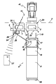
A top schematic view of a first exemplary embodiment of a dead livestock
collection system
according to the present invention can be seen in FIG.1. The collection system
of this first
exemplary embodiment comprises a dead livestock container 1, hereinafter
simply container
1, located at a collection site 2 close to a delimiting perimeter 3 of a farm
(not shown), said
container 1 being configured to receive dead livestock loaded by a farmer or
any other
suitable designated person.
The system of this exemplary embodiment further comprises a collection vehicle
6 that
comprises a driver cab 7, a collection box 8 and a loading mechanism 10
configured to grasp
the container 1, lift and tip, i.e. tilt, the container 1 to unload the dead
livestock contained in
the container 1 into the collection box 8 of the vehicle 6 through a top load
opening 9 and to
return the container 1 to its resting position. In this exemplary embodiment,
the collection
vehicle 6 comprises a top door 18 that is movable between an open position
which allows
Date Recue/Date Received 2023-11-28
10
access to the top load opening 9 and the inside of the collection box 8, and a
closed position
wherein the top load opening 9 is closed, and therefore, livestock cannot be
entered to the
collection box 8. The container 1 is preferably grasped and returned to the
collection site 2.
As will be explained in more detail hereinbelow, the loading mechanism 10 of
the collection
vehicle 6 can comprise a front lifting arm 17.
The system of the exemplary embodiment shown further comprises a refrigeration
chamber
4 dimensioned to enclose the container 1 and equipped with a refrigeration
unit 5 configured
to maintain the container refrigerated below a predetermined temperature. Said
temperature
is preferably 10 degrees Celsius, more preferably 8 degrees Celsius and even
more
preferably 8 degrees Celsius.
In the exemplary embodiment shown, the collection site 2 is located next to
the delimiting
perimeter 3 of the farm. However, in other embodiments simply being close to
the delimiting
perimeter 3 would suffice.
The system of this first exemplary embodiment comprises container translation
unit 13 (see
FIGS. 2 and 3) configured to move the container from the refrigeration chamber
4 to the
collection site 2 and from the collection site 2 to the refrigeration chamber
4 while a door 11
of the refrigeration chamber 4 is open. In order to do so, the system further
comprises a door
actuation unit 12 arranged to open and close said door 11 of the refrigeration
chamber 4.
Said door 11 is preferably a side door, i.e. is located at one of the lateral
faces of the
refrigeration chamber 4.
The collection site 2 shown has an inner access side 2a and an outer access
side 2b. The
container 1 at the collection site 2 is accessible to the farmer from inside
the delimiting
perimeter 3 through the inner access side 2a. The container 1 is accessible to
the collection
vehicle 6 from outside the delimiting perimeter 3 of the farm through the
outer access side
2b.
In the exemplary embodiment shown, the collection vehicle 6 comprises a
loading control 16
within the driver's cab 7, said loading control 16 being configured to control
the loading
mechanism 10 of the collection vehicle 6. As the loading control 16 is located
within the cab
7, the driver does not need to step out of the collection vehicle 6, thus
avoiding the risk of
contamination that could occur when standing close to the farm, and in
particular, close to
the collection site 2. Therefore, the worker health and safety is increased.
Moreover, this also
reduces the risk of spreading virus, contamination, etc. from one farm to
another, which is
also very desirable.
Date Recue/Date Received 2023-11-28
11
In the exemplary embodiment shown in FIG. 1, the system further comprises a
indoor signal
transmitter 14 arranged to be operated from inside the delimiting perimeter 3
of the farm and
an outdoor signal transmitter 15 arranged to be operated from inside the
driver's cab 7 of the
collection vehicle 6, the indoor signal transmitter 14 and the outdoor signal
transmitter 15
being configured to emit wireless signals for activating the door operating
means 12 and the
container translation unit 13. The outdoor signal transmitter 15 allows the
driver to move the
container 1 to the collection site 2, and vice versa, without needing to leave
the cabin of the
vehicle, with the advantages previously described associated to this effect.
Similarly the
indoor signal transmitter 14 allow the farmer or any other designated person
to wirelessly
move the container 1 to the collection site 2, and vice versa, thus avoiding
the risk of
contamination associated with touching elements which have been in close
relationship with
dead livestock.
The refrigeration chamber 4 of the system of the exemplary embodiment shown in
FIG. 1
comprises one or more sensors 24 that together with a computing device 25,
determine
when the content of the container 1 needs to be collected. Said sensors may
be, for
example, an ultrasound sensor for detecting the volume of dead livestock
within the
container, a gas detector for detecting certain gases caused by the decay of
the carcasses, a
camera that allows visual inspection, by a human or an artificial
intelligence, of the visual
aspect of the livestock, a timer activated the first time a carcass is placed
inside the
container, etc.
Once the computing device 25, based on the information provided by the one or
more
sensors 24, determines that the container 1, and in particular, its content,
should be
collected, it may alert the farmer to arrange for collection. Moreover, in
embodiments such as
the one shown in FIG. 1 which further comprise a signal emitter 26 connected
to the
computing device 25, which is configured to automatically send a collection
message to a
collection control station 27, the farmer may not need to do anything as the
system itself
arranges for the collection of the container 1 when it determines that it is
time to do so. Said
signal emitter 26 is preferably a radio signal emitter 26 as radio provides a
long signal range.
The control station 27 is in charge of programming collection routes of the
collection vehicles
when the computing device 25 has determined a collection need. Said control
station 27 can
be humanly operated on can also be automated.
Dead livestock or carcasses can be placed inside the container 1 at the
collection site 2 with
the aid of a carcass transport device 41. Depending on the size and weight of
the livestock to
be treated, said carcass transport device 41 can be, for example a bulldozer,
a crane, etc. If
Date Recue/Date Received 2023-11-28
12
the regulations, and size and weight of the livestock, so allow, dead
livestock can also be
loaded into the container 1 manually, although this situation should be
avoided as it
increases the risk of contamination of the farmer or designated person
manually loading the
dead livestock.
In this exemplary embodiment the collection box 8 of the collection vehicle 6
is configured to
tilt and comprises a rear discharge door 36 hinged to an axis 37 (see FIG. 6)
that allows for
an easy discharge of the dead livestock once the collection vehicle 6 arrives
at the
processing facility.
The collection box 8 of the collection vehicle 6 can also be refrigerated, so
that the
temperature of the dead livestock is kept below a predetermined threshold and
its decay is
slower. However, as the collection vehicle 6 does not typically store the dead
livestock in the
collection box 8 for a long period of time, it is not necessary that all
collection vehicles 6 have
a refrigerated collection box 8, although in certain circumstances can be
advantageous.
Although the exemplary embodiment depicted in FIG. 1 only comprises one
refrigeration
.. chamber 4 which is configured to house and refrigerate one container 1,
other embodiments
of the present invention could comprise more than one refrigeration chamber 4,
each one
being configured to house and refrigerate a corresponding container 1. In
other
embodiments, it is also possible that a single refrigeration chamber 4 is
configured to house
and refrigerate more than one container 1. In case of multiple refrigeration
chambers 4, each
chamber 4 can have its own refrigeration unit 5 or a single refrigeration unit
5 can refrigerate
two or more refrigeration chambers 4.
In the present document, livestock is understood to designate cattle, swine,
sheep, goats,
poultry, horses, rabbit, etc. The system of the present invention is
dimensioned depending on
the characteristics, in particular, size and weight, of the livestock to be
treated.
FIGS. 2 and 3 show a perspective view of the refrigeration chamber 4 together
with its
associated container translation unit 13 of the first exemplary embodiment of
a system
according to the present invention shown in FIG. 1.
As can be seen, in the exemplary embodiment shown the refrigeration chamber 4
comprises
a sliding door 11 at one of the ends thereof. However, in other embodiments
said door 11 can
be of any other type, for example, a swing door, i.e. a hinged door. The
system further
comprises a door actuation unit 12 arranged to open and close said door 11 of
the
refrigeration chamber 4. Although in FIGS. 2 and 3 said actuation unit 2 has
been depicted
Date Recue/Date Received 2023-11-28
13
on top of the refrigeration chamber 4, in other embodiments, can be placed in
any other
suitable location.
Attached to the opposite end of the sliding door 11, the refrigeration chamber
4 shown
comprises a refrigeration unit 5 configured to maintain the inside of the
refrigeration chamber
4 at a temperature on or below a predetermined temperature, which can be, for
example, 8
degrees Celsius, so that the carcasses in the container 1 inside said
refrigeration chamber 4
do not decay as fast as if they were at ambient temperature. It should be
borne in mind that
depending on the location and time of the year, for example, under direct
sunlight at summer,
temperatures can be really high, and thus, carcasses decay very fast. In such
circumstances,
it could be necessary to collect the carcasses every day. The system of the
present invention
allows for longer periods between each collection of the dead livestock.
The container translation unit 13 (see FIG. 1) of the exemplary embodiment
shown
comprises guide elements 38 arranged between the interior of the refrigeration
chamber 4
and the collection site 2, a support platform 39 configured to support the
container 1, and a
translation actuator (not shown), configured to move the support platform 39
along the guide
elements 38. Said translation actuator may be, for example, a hydraulic
piston, a motor of the
support platform, a rack and pinion gear, etc. By moving the support platform
39 along the
guide elements 38, the container 1 can be moved from the inside of the
refrigeration
chamber 4 to the collection site 2, and vice versa.
In order to minimize an increase of temperature of the refrigeration chamber 4
when the door
11 is open when it is needed to move the support platform 39, and in
particular, the container
1 to the collection site 2, the system can only open the door and extract the
container 1 when
the farmer or the collection vehicle 6 are in place and ready to load
livestock on the container
1 or unloading the container 1 to the collection vehicle 6, depending on the
case. If the
loading or unloading operations need to take longer than usual for any reason,
it is also
possible that the door actuation unit 12 closes the door 11 while the
container is at the
collection site 12 and opens it again right before the container 1 is ready to
be brought back
to the inside of the refrigeration chamber 4. Once the container 1 is back in
the refrigeration
chamber 4 the door 11 closes until the next loading or unloading operation of
the container 1.
Moreover, the computing device 25 may also be configured to register and store
the time that
the door 11 is open, the time that the container 1 is at the collection site
2, temperature drop
of the refrigeration chamber 4, temperature increase of the livestock stored
in the container
1, etc. The system may also be configured to issue reports of such operating
parameters.
Date Recue/Date Received 2023-11-28
14
FIGS. 4 and 5 show an elevation and a top view, respectively, of the
collection vehicle 6
grasping the dead livestock container 1 at the collection site 2 of the first
exemplary
embodiment of a system according to the present invention. The loading
mechanism 10 of
the collection vehicle 6 of this first exemplary embodiment of a system
according to the
present invention comprises a front lifting arm 17 equipped with two opposite
forks 32 facing
one another and configured to be inserted in corresponding sleeves 40 of the
container 1,
which in the present case, is a front lift container 1.
Said front lifting arm 17 is operated by the driver of the collection vehicle
6, or any other
suitable person, from inside the driver's cab 7 in order to avoid any possible
contamination of
the operator, thus increasing the health and safety of the worker and avoiding
the risk of
spreading any contamination that could be present at the collection site 2, or
near it, to other
livestock farms.
The collection box 8 of the collection vehicle 6 of this exemplary embodiment
comprises a
top door 18 for opening and closing the top load opening 9 of the collection
box 8, that is to
say, the sliding top door 18 opens and closes the collection box 8 and is
driven by a top door
actuator 19, which in this case, is a hydraulic cylinder, although in other
embodiments can be
a different kind of actuator.
Said top door 18 preferably provides a liquid tight seal of the top load
opening 9 when it is in
its closed position, so that, for example, rain, does not leak into the
collection box 8. In
certain embodiments, said top door 18 can also provide a gas tight seal, thus
avoiding any
leakage to the outside of the vehicle 6 of gases result of the decay of the
dead livestock
inside the collection box 8.
In the exemplary embodiment shown, the top door 18 is a sliding top door 18.
However, in
other embodiments said top door 18 can be, for example, a swing door or any
other kind of
suitable door. In the exemplary embodiment shown, the top door 18 is a single
leaf door,
although in other embodiments said top door 18 can have two or more leaves.
The collection vehicle 6 shown further comprises a protruding front portion 20
of the
collection box 8 and the top loading opening 9 spans a front part of the
collection box 8
including the protruding front portion 20. However, in other embodiments the
collection box
20 can lack such protruding front portion 20 in which case the top loading
opening 9 only
spans the top side of the collection box 8. It is also possible that in
embodiments wherein the
collection box 8 comprises a protruding front portion 20 the top loading
opening 9 does not
extend to such protruding front portion 20.
Date Recue/Date Received 2023-11-28
15
The collection vehicle 6 of this exemplary embodiment is a tipper truck, or
simply a tipper,
that is to say, its collection box 8 is configured to tilt and has a rear
discharge door 36 hinged
to a horizontal axis 37 for unloading the dead livestock stored in the
collection box 8.
However, in other embodiments the collection vehicle 6 may not be a tipper
truck and the
dead livestock inside the collection box 8 may be unloaded in a different
manner.
The collection vehicle 6 of this exemplary embodiment comprises six wheels 22
equipped
with a corresponding disinfection device 23 that is described in more detail
in the context of
FIG. 7. In other embodiments the collection vehicle 6 can have a different
number of wheels
22, and even have tracks instead of wheels, for example.
FIG. 6 shows in an elevation view the collection vehicle 6 of the first
exemplary embodiment
of a system according to the present invention unloading the dead livestock
container 1. As
can be seen, in order to unload the container 1 into the collection box 8 of
the vehicle 6, the
loading mechanism 10 lifts the container 1 and places it above the top load
opening 9 so that
by tipping the container 1 it unloads the dead livestock stored therein into
the collection box 8
of the vehicle 6 through the top loading opening 9, as the dead livestock
falls by gravity.
FIG. 7 shows a detail view of a wheel 22 and its corresponding disinfection
device 23 of the
collection vehicle 6 shown in FIGS. 4 to 6. The collection vehicle 6 comprises
a disinfection
device 23 for each of its wheels 22 configured to spray a disinfectant liquid
on the wheel
treads when the collection vehicle starts moving 6 so that the whole
circumference of the
wheel 22 is sprayed with the disinfectant liquid. The wheels 22 are preferably
sprayed once
the collection vehicle 6 has returned the container 1 to the collection site 2
after unloading its
content into the collection box 8.
Optionally, the spraying of the wheels 22 with disinfectant liquid can be
repeated once the
collection vehicle has departed the farm facilities and its at a predetermined
distance from it,
to ensure that while the collection vehicle 6 departed the facility no
contamination is spread,
even if the wheels 22 were contaminated while the collection vehicle 6 was
departing the
farm facility after returning the container 1 to the collection site 2.
The disinfection device 23 sprays disinfectant to the wheels 22 at least until
the wheel 2
completes a full revolution, although more than one revolution is preferred in
order to ensure
that the disinfectant liquid has wetted the whole tread of the wheel 22.
FIG. 8 shows a detail view of a container disinfection device 21 of the
collection vehicle 6
shown in FIGS. 4 to 7 disinfecting a dead livestock container 1. FIG. 9 shows
a view in
greater detail view of the container disinfection device 21 shown in FIG. 8.
Date Recue/Date Received 2023-11-28
16
Once the content of the container 1 has been unloaded into the collection box
8 through the
top load opening 9, the loading mechanism 10 maintains the container 1 lifted
and tipped, so
that a container disinfection device 21 can spray disinfectant into the inside
of the container
21 in order to disinfect it and avoid a potential source of contamination.
In the exemplary embodiment shown the disinfection device 21 comprises a
foldable arm
which comprises a plurality of spray nozzles that spray the disinfectant into
the inside of the
container. The disinfection 21 device of this exemplary embodiment moves to an
operating
position when it needs to spray disinfectant into the container and returns to
an inoperative
position once the spraying operation has ended.
Once the container 1, and in particular its inside, has been sufficiently
sprayed with the
disinfectant liquid by the disinfecting device 21, the disinfecting device 21
moves to its
inoperative position (shown with dotted lines in FIG. 8), and the loading
mechanism 10
returns the container 1 to the collection site 2.
FIGS. 10 and 11 show a side and a perspective view, respectively, of a dead
livestock
container 1 of a second exemplary embodiment of a dead livestock collection
system
according to the present invention. The container 1 of this exemplary
embodiment comprises
foldable wall extensions 28 arranged on top edges 29 of opposite side walls 30
thereof. In
this exemplary embodiment, the foldable wall extensions 28 are hinged about an
axis at an
end of the top edges 29 to move from a folded position to an unfolded
position, and vice
versa. In the folded position, the foldable wall extensions 28 are hidden and
do not protrude
from the top edge 29 of the walls 30 of the container, whereas in the unfolded
position said
foldable wall extensions 28 cover a space between the top edges 29 of the side
walls 30 of
the container 1 and side edges of the top loading opening 9 of the collection
box 8 of the
collection vehicle 6 when the container is held by the loading mechanism 10 in
a tipped
position (see FIG. 12).
The container 1 of this second exemplary embodiment comprises a spring device
(not
shown) configured to drive the foldable wall extensions 28 to the unfolded
position and a
retaining mechanism 34 configured to retain the foldable wall extensions 28 in
the folded
position. Said retaining mechanism 34 is configured to cooperate with the
front lifting arm 17,
and in particular, with its forks 32, to release the retention mechanism 34
when the front
lifting arm 17 grips the container 1 through its sleeves 40. When the
retention mechanism 34
is released by the forks 32, the spring device drives the foldable wall
extensions 28 from the
folded position to the unfolded position.
Date Recue/Date Received 2023-11-28
17
In order to return the foldable wall extensions 28 to its folded position from
its unfolded
position, the system of the present invention can comprise a folding mechanism
configured
to fold the folding wall extensions 28 until they are retained in the folded
position by the
retaining mechanism. Said folding mechanism is preferably driven by a motor
and can be
mounted on the container 1 or on the container translation unit 13.
The container 1 of the first exemplary embodiment shown in FIGS. 1 to 9 lacks
such foldable
wall extensions 28.
The container 1 shown in FIGS. 10 and 11 is a lidless container, that is to
say, this container
1 is open on its upper side. As the container is kept inside the refrigeration
chamber 4, which
is closed, at a temperature on or below a predetermined threshold, it is not
necessary that
the container 1 is closed. A lidless container 1 eases the loading and
unloading operations.
However, in other embodiments the container 1 can have a lid that closes it
and which is
open to load and unload dead livestock to/from it.
FIG. 12 shows the container 1 of the second exemplary embodiment of a system
according
to the present invention when it is being emptied into the collection box 8 of
the collection
vehicle 6.
As explained before, at least, in the context of FIG. 6, in order to empty the
container 1 into
the collection box 8 of the vehicle 6, the loading mechanism 10 grasps de
container 1 at the
collection site 2, lifts it until is placed above the top load opening 9 and
tips it so that the
contents of the container 1, that is to say, the dead livestock, falls by
gravity into the
collection box 8 by gravity. As a result of the decay of the carcasses inside
the container 1,
liquid may be present in it. Specially in case of wind at the collection site
2, when the
container 1 is emptied, said liquid may be spilled outside the top load
opening 9. Spillage of
decomposition liquid outside the collection box 8 should be avoided as it
poses a risk of
contamination. The foldable wall extensions 28 aid to prevent said spillage of
liquid,
carcasses and/or parts thereof, as it protects it from wind and guides the
content of the
container 1 to the top load opening 9 of the collection box 8.
Date Recue/Date Received 2023-11-28