Note: Descriptions are shown in the official language in which they were submitted.
W02022/261712
PCT/AU2022/050599
- 1 -
A METHOD AND SYSTEM FOR LOGGING DATA FOR A MINERAL SAMPLE
Related Applications
The present application claims convention priority from
Australian provisional patent application no. 2021901798
(filed on 16 June 2021) and Australian provisional patent
application no. 2022900471 (filed on 28 February 2022).
The entire contents of both is incorporated herein by
io reference in their entirety.
Field of the Invention
The present invention relates to a method and system for
is logging data for a mineral sample, such as but not limited
to drill-hole logging data.
Background
20 Mining explorations typically involve obtaining mineral
samples from a drill site and evaluating the composition of
those samples to determine whether a resource is present at
the site. One technique for obtaining mineral samples is
reverse circulation (RC) drilling, where drill cuttings or
25 chips are brought to the surface by a circulation of air
through the drill. Samples of drill chips are typically
collected for regular depth intervals during drilling (e.g.
2 metre intervals) to evaluate the mineral composition
throughout a length of the drill-hole.
For each interval, a sample of drill chips may be logged
and another sample may be sent to a laboratory for
analysis, for example by X-ray fluorescent (XRF) analysis
or Fourier Transform Infrared (FTIR) analysis. Field
logging of drill-hole samples involves visually inspecting
the samples and recording the material types present as
CA 03221595 2023- 12- 6
WO 2022/261712
PCT/AU2022/050599
- 2 -
well as other physical characteristics such as colour,
shape and texture.
Field logging is a routine practice typically done by
geologists. While compositional assay can reveal the
elemental composition of a sample, field logging is
necessary to determine geological material types present in
a sample, such as hematite, goethite, shale etc.
Information regarding both the composition and material
type of drill samples is necessary to better understand the
structures and mineralogical compositions of an area. Such
information can then be used for ore-body modelling and the
development of mining plans.
is The accuracy of the field logging data is therefore
important for resource evaluation and planning in the
minerals industry. However, inaccuracies in the material
types logged may arise not only due to complexities and
diversities in mineralisation and geology, but also due to
subjective biases and human error. There may also be
inconsistencies between thc logging performed by different
geologists. It is therefore common for the estimated
composition of the logged chips to differ from the actual
composition, and thus validation of the logging data is
required to check and/or improve its accuracy. Validation
can comprise steps to refine the logged material types and
corresponding percentages in order to improve the
consistency between the logging and laboratory-analysed
chemical composition of the geological sample.
For iron ore exploration and mining in particular,
incorrect drill-hole logging information can result in
outcomes with significant financial implications. For
example, material types such as ochreous goethite and shale
are commonly confused due to similarities in colour and
texture in chip samples obtained from RC drilling. However,
CA 03221595 2023- 12- 6
WO 2022/261712
PCT/AU2022/050599
- 3 -
chemically these material types are very different; for
instance, shale (kaolinite) is high in silica and alumina
and low in iron, whereas ochreous goethite has a high iron
grade but is much lower in silica and alumina than shale.
Furthermore, ochreous goethite tends to be sticky due to
its water holding capacity, which can cause problems such
as blocking screen decks and ore transfer chutes, leading
to unplanned downtime. Validation during iron ore
exploration can thus provide more accurate knowledge of the
distribution of ochreous goethite, which can assist in
planning blending strategies to manage risks in mining.
Logging and is also an extremely time consuming and labour-
intensive task, given that on average each 2 metre interval
of an RC drill-hole for example may take a number of
minutes to log, and validate and there may be hundreds of
kilometres of RC drill-holes drilled each year.
A system integrating methods for logging using objective
measurements therefore presents advantages in terms of
accuracy, speed and rcpcatability, and reductions in labour
over the existing geologist-driven process.
The present disclosure develops on concepts disclosed in
the Applicant's earlier PCT application no.
PCT/AU2018/050046 (published as WO 2018/136998 Al). This
earlier disclosure is incorporated herein in its entirety.
This disclosure may be consulted to better understand
aspects of this disclosure. However, it should be
understood that the present disclosure supersedes that in
the earlier PCT application in relation to any perceived
contradiction.
CA 03221595 2023- 12- 6
WO 2022/261712
PCT/AU2022/050599
- 4 -
Summary of the Invention
Disclosed herein is a logging system for logging data
obtained for a sample, comprising: a data input system
configured to receive input logging data and assay data
associated with the sample; and a data logging controller
comprising a processor and a memory, the memory storing
program instructions configured to cause the processor to
implement: an infrared material type logger configured to:
receive infrared spectra associated with the sample;
process the infrared spectra using a pre-trained machine
learning algorithm or a statistical algorithm to generate
one or both of: an initial material type abundance estimate
for the sample, wherein the initial material type abundance
estimate is an estimate of the presence of one or more
particular material types within the sample and an estimate
of the relative abundance of each said material type, and
an initial lump percentage estimate for the sample; and
store the generated initial material type abundance
estimate and/or initial lump percentage estimate in the
memory.
The infrared spectra may be generated using Fourier
transform infrared (FTIR) spectroscopy. The sample may be
prepared for FTIR spectroscopy using one or both of:
dehydration; and pulverisation, preferably wherein the
pulverisation is performed in two stages, first to about 3
mm and second to about 150 microns.
Optionally, the infrared material type logger is further
configured to: resample the received infrared spectra to a
predefined common set of wavenumbers. The received infrared
spectra may be resampled to a common set of 2966 integer
wavenumbers within a predefined range.
CA 03221595 2023- 12- 6
WO 2022/261712
PCT/AU2022/050599
- 5 -
Optionally, the infrared material type logger is further
configured to: clip the received infrared spectra to
theoretical minimum and/or maximum values. The infrared
spectra may be clipped according to a minimum value greater
than 0, such as 0.11.
Optionally, the infrared spectra are obtained from a known
Fourier transform infrared (FTIR) spectrometer and are pre-
processed for baseline removal, wherein the baseline
io removal uses a baseline removal algorithm defined by one or
more predetermined parameters, and wherein said parameters
are predetermined based on an optimisation parameter search
and a comparison between FTIR spectra pairs sourced from
the FTIR spectrometer and another FTIR spectrometer. The
is infrared spectra may be adjusted FTIR spectra, each
generated by normalising its removed baseline and combining
said normalised baseline and the FTIR spectrum after
baseline removal.
20 The infrared spectra may be processed using a pre-trained
machine learning algorithm, whcrcin thc pro-training
utilises a training set of infrared spectra, each labelled
with logged material type compositions and/or lump
percentages represented by the infrared spectra. The
25 training set may comprise infrared spectra associated with
known samples extracted from different project areas.
The infrared spectra may be processed using a ridge
regression algorithm.
Optionally, the infrared material type logger is further
configured to: perform a search on a generated initial
material type abundance estimate and/or lump percentage
estimate, the search configured to identify one or more
groups, each of two or material types with correlated
errors, based on a rule indicative of a threshold
CA 03221595 2023- 12- 6
WO 2022/261712
PCT/AU2022/050599
- 6 -
correlation of errors of members of the group. The search
may be a greedy tree search. Optionally, the infrared
material type logger is further configured to: remove
individual constituents of identified group(s) from the
initial material type abundance estimate and/or lump
percentage estimate.
Also disclosed herein is a logging system for logging data
obtained for a sample, comprising: a data input system
configured to receive input logging data and assay data
associated with the sample; and a data logging controller
comprising a processor and a memory, the memory storing
program instructions configured to cause the processor to
implement: a photographic image logger configured to:
is receive one or more photographs of the sample; process the
one or more photographs using a pre-trained machine
learning algorithm to generate one or both of: an initial
material type abundance estimate for the sample, wherein
the initial material type abundance estimate is an estimate
of the presence of one or more particular material types
within the sample and an estimate of thc relative abundance
of each said material type, and an initial lump percentage
estimate for the sample; and store the generated initial
material type abundance estimate in the memory.
The pre-trained machine learning algorithm may comprise a
pre-trained general image classification neural network.
The image classification neural network may be modified by
removing a final general image classification layer of the
network while preserving a prior lower-level training, and
training a new final classification layer for classifying
the presence of specific material types.
Optionally, the photographic image logger is further
configured to: partition the one or more photographs into
partitions; process each partition separately using the
CA 03221595 2023- 12- 6
WO 2022/261712
PCT/AU2022/050599
- 7 -
machine learning algorithm; and utilise a prediction model
applied to each processed partition to generate the initial
material type abundance. The prediction model may comprise
a multiple linear regression algorithm treating each
processed partition as a unique independent variable.
Also disclosed herein is a logging system for logging data
obtained for a sample, comprising: a data input system
configured to receive input logging data and assay data
associated with the sample; and a data logging controller
comprising a processor and a memory, the memory storing
program instructions configured to cause the processor to
Implement: a photographic image logger configured to:
receive one or more photographs of the sample; process the
is one or more photographs to generate one or more visual cue
classifications for the sample; and store the generated
visual cue classifications in the memory.
The one or more visual cues may be selected from: a primary
colour of the sample; a secondary colour of the sample; a
representative distribution of chip shapes; and textural
cues.
Optionally, the photographic image logger is further
configured to: determine a primary colour and/or a
secondary colour of the sample by: an assessment of a
histogram of the photograph(s); or determining an average
colour within the photograph. In an alternative option, the
photographic image logger is further configured to:
determine a primary colour and/or a secondary colour of the
sample by: utilising a neural net classifier pre-trained
with a training set of images, each labelled with a primary
colour.
The photograph(s) may be divided into image patches and
each patch may have a primary colour and/or secondary
CA 03221595 2023- 12- 6
WO 2022/261712
PCT/AU2022/050599
- 8 -
colour determined, and a majority of a colour
classification selected as the primary colour and/or a next
biggest majority selected as the secondary colour.
Optionally, the photographic image logger is further
configured to: determine a representative chip shape
classification for the sample by: using a suitable pre-
trained neural net classifier; or by assessing individual
chip shape outlines.
io
In an embodiment, one photograph is taken of a sample. In
another embodiment, a plurality of photos are taken of a
sample to enable a 3-dimensional reconstruction.
is Optionally, the photographic image logger is further
configured to: calibrate the photograph(s) by: determining
calibration data associated with the camera(s) taking the
photograph(s) by capturing an image(s) with said camera(s)
of a known calibration target and comparing an appearance
20 of the calibration target in the image(s) to the known
appearance of thc calibration target. Thc calibration data
may be suitable for: accounting for a white balance applied
by the camera(s); and/or accounting for distance
distortions in the image(s).
Also disclosed herein is a logging system for logging data
obtained for a sample, comprising: a data input system
configured to receive input logging data and assay data
associated with the sample; and a data logging controller
comprising a processor and a memory, the memory storing
program instructions configured to cause the processor to
implement: a measurement data logger configured to: receive
drilling measurement data corresponding to one or more
measurements made in relation to, and during, extraction of
the sample; process the measurement data using a pre-
trained machine learning algorithm to generate an estimate
CA 03221595 2023- 12- 6
WO 2022/261712
PCT/AU2022/050599
- 9 -
of the presence of particular material types of the sample;
and store the estimate of the presence of particular
material types in the memory.
The measurement data may include one of more of: holdback
pressure; holdback force; pushdown pressure; pushdown
force; penetration rate; torque pressure; torque force;
weight on bit; drill string weight; water volume; air flow
rate; air pressure; rotation rate; drill string vibration
frequency; drill string vibration amplitude; and drill
string vibration acceleration.
Optionally, the measurement data logger is configured to
utilise a bag-level randomised tree algorithm and/or a
is Random Forests algorithm in order to produce an estimate of
the presence of material types in the sample.
Also disclosed herein is a logging system for logging data
obtained for a sample, comprising: a data input system
configured to receive input logging data and assay data
associated with the sample; and a data logging controller
comprising a processor and a memory configured to implement
two or more of: the infrared material type logger of the
logging system described above; either or both photographic
image logger of the logging systems described above; the
photographic image logger of the logging system described
above; and the measurement data logger of the logging
system described above.
Also disclosed herein is a logging system for logging data
obtained for a sample, comprising: a data input system
configured to receive input logging data and assay data
associated with the sample; and a data logging controller
comprising a processor and a memory, the memory storing
program instructions configured to cause the processor to
implement: receive an initial material type abundance
CA 03221595 2023- 12- 6
WO 2022/261712
PCT/AU2022/050599
- 10 -
estimate associated with the sample; receive assay data
indicative of an actual composition of the sample or
another mineral sample provided from the region of
interest; receive a lump percentage estimate associated
with the sample; modify the material type abundance
estimate based on one or more optimisation criteria and the
received assay data and/or lump percentage estimate,
wherein the optimisation criteria include one or more of:
material type addition criteria, wherein a material type is
added to the material type abundance estimate according to
the presence of one or more other material types in the
material type abundance estimate and an associated
predefined addition rule; and/or material type removal
criteria, wherein a material type is removed from the
is material type abundance estimate according to a predefined
removal rule.
Also disclosed herein is a logging system for logging data
obtained for a sample, comprising: a data input system
configured to receive input logging data and assay data
associated with the sample; and a data logging controller
comprising a processor and a memory, the memory storing
program instructions configured to cause the processor to
implement: receive an initial material type abundance
estimate associated with the sample; receive assay data
indicative of an actual composition of the sample or
another mineral sample provided from the region of
interest; receive a lump percentage estimate associated
with the sample; modify the material type abundance
estimate based on one or more optimisation criteria and the
received assay data and/or lump percentage estimate,
wherein the optimisation criteria include: defining one or
more sets of material types, each set comprising at least
two material types, such that a sum of the optimised
percentages of material types of a set identified in the
material type abundance estimate is within a tolerance of
CA 03221595 2023- 12- 6
WO 2022/261712
PCT/AU2022/050599
- 11 -
the sum of percentages of the material types of the set
before optimisation.
The tolerance may be between 0% and 10%.
Also disclosed herein is a logging system for logging data
obtained for a sample, comprising: a data input system
configured to receive input logging data and assay data
associated with the sample; and a data logging controller
io comprising a processor and a memory, the memory storing
program instructions configured to cause the processor to
implement: an infrared material type logger configured to:
receive infrared spectra associated with the sample;
process the infrared spectra using a pre-trained machine
is learning algorithm or a statistical algorithm to generate
one or both of: an initial material type abundance estimate
for the sample, wherein the initial material type abundance
estimate is an estimate of the presence of one or more
particular material types within the sample and an estimate
20 of the relative abundance of each said material type, and
an initial lump percentage estimate for the sample; and
store the generated initial material type abundance
estimate and/or initial lump percentage estimate in the
memory; receive assay data indicative of an actual
25 composition of the sample or another mineral sample
provided from the region of interest; receive a lump
percentage estimate associated with the sample; modify the
material type abundance estimate based on one or more
optimisation criteria and the received assay data and/or
30 lump percentage estimate.
Also disclosed herein is a logging system for logging data
obtained for a sample, comprising: a data input system
configured to receive input logging data and assay data
35 associated with the sample; and a data logging controller
comprising a processor and a memory, the memory storing
CA 03221595 2023- 12- 6
WO 2022/261712
PCT/AU2022/050599
- 12 -
program instructions configured to cause the processor to
implement: a photographic image logger configured to:
receive one or more photographs of the sample; process the
one or more photographs using a pre-trained machine
learning algorithm to generate one or both of: an initial
material type abundance estimate for the sample, wherein
the initial material type abundance estimate is an estimate
of the presence of one or more particular material types
within the sample and an estimate of the relative abundance
of each said material type, and an initial lump percentage
estimate for the sample; and store the generated initial
material type abundance estimate in the memory; and receive
assay data indicative of an actual composition of the
sample or another mineral sample provided from the region
is of interest; receive a lump percentage estimate associated
with the sample; modify the material type abundance
estimate based on one or more optimisation criteria and the
received assay data and/or lump percentage estimate.
Also disclosed herein is a logging system for logging data
obtained for a sample, comprising: a data input system
configured to receive input logging data and assay data
associated with the sample; and a data logging controller
comprising a processor and a memory, the memory storing
program instructions configured to cause the processor to
implement: a photographic image logger configured to:
receive one or more photographs of the sample; process the
one or more photographs to generate one or more visual cue
classifications for the sample; and store the generated
visual cue classifications in the memory; and receive an
initial material type abundance estimate associated with
the sample; receive assay data indicative of an actual
composition of the sample or another mineral sample
provided from the region of interest; receive a lump
percentage estimate associated with the sample; and modify
the material type abundance estimate based on the visual
CA 03221595 2023- 12- 6
WO 2022/261712
PCT/AU2022/050599
- 13 -
cue classifications and one or more optimisation criteria
and the received assay data and/or lump percentage
estimate.
Also disclosed herein is a logging system for logging data
obtained for a sample, comprising: a data input system
configured to receive input logging data and assay data
associated with the sample; and a data logging controller
comprising a processor and a memory, the memory storing
program instructions configured to cause the processor to
implement: a measurement data logger configured to: receive
drilling measurement data corresponding to one or more
measurements made in relation to, and during, extraction of
the sample; process the measurement data using a pre-
is trained machine learning algorithm to generate an estimate
of the presence of particular material types of the sample;
and store the generated estimate of the presence of
material types in the memory; and receive an initial
material type abundance estimate associated with the
sample; receive assay data indicative of an actual
composition of thc sample or another mineral sample
provided from the region of interest; receive a lump
percentage estimate associated with the sample; and modify
the material type abundance estimate based on the estimate
of the presence of material types and one or more
optimisation criteria and the received assay data and/or
lump percentage estimate.
Also disclosed herein is a logging method for logging data
obtained for a sample implemented by a data logging
controller comprising a processor and a memory, the memory
storing program instructions configured to cause the
processor to implement the steps of: receiving infrared
spectra associated with the sample; processing the infrared
spectra using a pre-trained machine learning algorithm or a
statistical algorithm to generate one or both of: an
CA 03221595 2023- 12- 6
WO 2022/261712
PCT/AU2022/050599
- 14 -
initial material type abundance estimate for the sample,
wherein the initial material type abundance estimate is an
estimate of the presence of one or more particular material
types within the sample and an estimate of the relative
abundance of each said material type, and an initial lump
percentage estimate for the sample; and storing the
generated initial material type abundance estimate and/or
initial lump percentage estimate in the memory.
io Also disclosed herein is a logging method for logging data
obtained for a sample implemented by a data logging
controller comprising a processor and a memory, the memory
storing program instructions configured to cause the
processor to implement the steps of: receiving one or more
is photographs of the sample; processing the one or more
photographs using a pre-trained machine learning algorithm
to generate one or both of: an initial material type
abundance estimate for the sample, wherein the initial
material type abundance estimate is an estimate of the
20 presence of one or more particular material types within
thc sample and an estimate of thc relative abundance of
each said material type, and an initial lump percentage
estimate for the sample; and storing the generated initial
material type abundance estimate in the memory.
Also disclosed herein is a logging method for logging data
obtained for a sample implemented by a data logging
controller comprising a processor and a memory, the memory
storing program instructions configured to cause the
processor to implement the steps of: receiving one or more
photographs of the sample; processing the one or more
photographs to generate one or more visual cue
classifications for the sample; and storing the generated
visual cue classifications in the memory.
CA 03221595 2023- 12- 6
WO 2022/261712
PCT/AU2022/050599
- 15 -
Also disclosed herein is a logging method for logging data
obtained for a sample implemented by a data logging
controller comprising a processor and a memory, the memory
storing program instructions configured to cause the
processor to implement the steps of: receiving drilling
measurement data corresponding to one or more measurements
made in relation to, and during, extraction of the sample;
processing the measurement data using a pre-trained machine
learning algorithm to generate an estimate of the presence
io of particular material types of the sample; and storing the
estimate of the presence of particular material types in
the memory.
Also disclosed herein is a logging method for logging data
is obtained for a sample implemented by a data logging
controller comprising a processor and a memory, the memory
storing program instructions configured to cause the
processor to implement the steps of: receiving an initial
material type abundance estimate associated with the
20 sample; receiving assay data indicative of an actual
composition of thc sample or another mineral sample
provided from the region of interest; receiving a lump
percentage estimate associated with the sample; modifying
the material type abundance estimate based on one or more
25 optimisation criteria and the received assay data and/or
lump percentage estimate, wherein the optimisation criteria
include one or more of: material type addition criteria,
wherein a material type is added to the material type
abundance estimate according to the presence of one or more
30 other material types in the material type abundance
estimate and an associated predefined addition rule; and/or
material type removal criteria, wherein a material type is
removed from the material type abundance estimate according
to a predefined removal rule.
CA 03221595 2023- 12- 6
WO 2022/261712
PCT/AU2022/050599
- 16 -
Also disclosed herein is a logging method for logging data
obtained for a sample implemented by a data logging
controller comprising a processor and a memory, the memory
storing program instructions configured to cause the
processor to implement the steps of: receiving an initial
material type abundance estimate associated with the
sample; receiving assay data indicative of an actual
composition of the sample or another mineral sample
provided from the region of interest; receiving a lump
percentage estimate associated with the sample; modifying
the material type abundance estimate based on one or more
optimisation criteria and the received assay data and/or
lump percentage estimate, wherein the optimisation criteria
include: defining one or more sets of material types, each
is set comprising at least two material types, such that a sum
of the optimised percentages of material types of a set
identified in the material type abundance estimate is
within a tolerance of the sum of percentages of the
material types of the set before optimisation.
Also disclosed herein is a method for training an anomaly
detector for anomaly detection in respect of Fourier
transform infrared (FTIR) spectroscopy spectra, said
anomaly detector implementing a neural network, comprising:
obtaining a plurality of training samples comprising FTIR
spectra associated with samples associated with a common
class; undertaking unsupervised training of the neural
network, such that the trained neural network is configured
to determine one or more latent variables for spectrum
reconstruction when provided with a FTIR spectrum as an
input, such that the trained neural network generates a
pseudospectrum in response to receiving an FTIR spectrum as
an input.
Optionally, the method comprises: subsequently to training
the neural network, for each training sample: generating an
CA 03221595 2023- 12- 6
WO 2022/261712
PCT/AU2022/050599
- 17 -
associated pseudospectrum using the trained neural network
with the training sample as an input, and determining a
score indicative of a similarity between the training
sample and its associated pseudospectrum; comparing the
scores against a distribution and removing training samples
outside of the distribution; and retraining the neural
network using the non-removed training samples. The
distribution may be a normal distribution. The score may be
based on a calculated reconstruction error for each
io training sample. The score may be based on a calculated
reconstruction probability for each training sample. In
this case, each score may be calculated by: calculating a
reconstruction probability for each wavenumber of the FTIR
spectrum; summing said reconstruction probabilities across
is the entire FTIR spectrum to thereby generate the score.
Optionally, the method comprises: undertaking further
testing for neural network optimisation and hyperparameter
testing.
Thc neural network may bc based on a variational
auto encoder.
Also disclosed herein is a method of anomaly detection in
respect of Fourier transform infrared (FTIR) spectroscopy
spectra, comprising: obtaining an FTIR spectrum for anomaly
detection associated with a sample; calculating a score for
said spectrum using an anomaly detector implementing a
neural network trained according to the method previously
disclosed, said anomaly detector associated with a same
class as that of the sample; and comparing the score
against a predefined threshold configured for identifying
anomalies.
The anomaly detector may be selected from a plurality of
anomaly detectors each associated with a different class.
CA 03221595 2023- 12- 6
WO 2022/261712
PCT/AU2022/050599
- 18 -
Optionally, in respect to the comparison between the score
and the predefined threshold indicating an anomaly, the
method comprises recording an anomaly flag in association
with the FTIR spectrum.
Also disclosed herein is an anomaly detector for anomaly
detection in respect of Fourier transform infrared (FTIR)
spectroscopy spectra, said detector configured for applying
the method disclosed above to provided FTIR spectra.
Also disclosed herein is a computer program or computer
readable medium comprising a computer program, the program
comprising code configured to cause a processor to
is implement at least one of the above methods.
Various aspects described above can be implemented together
providing the combined benefits¨for example, various
loggers defined as implemented by the aspects of a logging
system may be implemented within a common logging system.
Brief Description of Drawings
In order that the invention may be more clearly understood,
embodiments will now be described, by way of example, with
reference to the accompanying drawings, in which:
Figure 1 is a flow diagram of a method according to an
embodiment.
Figure 2 is schematic diagram of a system according to an
embodiment.
Figures aA and 3E, relate to a method for generating
estimate of initial material type abundance of a sample
CA 03221595 2023- 12- 6
WO 2022/261712
PCT/AU2022/050599
- 19 -
using Fourier transform infrared spectrum analysis
according to an embodiment.
Figures 3C to 3F relate to a method of baseline removal.
Figure 3C shows a discrepancy between FTIR spectra for the
same sample due to a difference in baseline, Figure 3D
shows an absorbance difference distribution for a number of
samples measured on two different FTIR spectrometers,
Figure 3E shows the effect of baseline removal on two FTIR
io spectra of the same sample, and Figure 3F shows a method
for identifying baseline removal parameter(s).
Figures 4A to 4C relate to a technique of using photographs
of a sample to determine visual cues and/or an estimate of
is initial material type abundance of a sample according to an
embodiment.
Figure 5 shows an exemplary relationship between functional
features of the system of Figure 2, according to an
20 embodiment.
Figures 6_A_ and 6B relate to an optimisation process
implemented by an optimisation module of the system of
Figure 2 according to an embodiment.
Figures 7A to 7F relate to an embodiment including a neural
network implemented anomaly detector for FTIR spectra.
Detailed Description
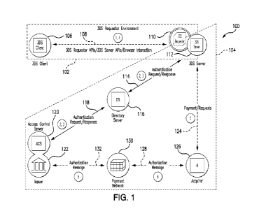
Figure 1 is a flowchart of a method of logging data for a
mineral sample according to an embodiment. The method 100
will herein be described in the context of iron ore mining
exploration using reverse circulation (RC) drilling to
obtain mineral samples. However, a person skilled in the
art will appreciate that the disclosed method can be used
CA 03221595 2023- 12- 6
WO 2022/261712
PCT/AU2022/050599
- 20 -
in other applications and can involve other drilling
techniques.
Throughout this specification, unless the context requires
otherwise due to express language or necessary implication:
= The term 'composition" and variants thereof refer to a
chemical composition of a material, i.e. a set of
chemical elements and/or compounds, such as but not
io limited to Fe, SiO2, A1203, P, S, Mn, MgO, Ti02, CaO,
H20, which might be present in a mineral sample. The
term "composition" may also be used in a manner that
refers to the amounts or proportions of these chemical
elements and/or compounds present in a mineral sample.
is
= The term 'material type" refers to a type of material
characterised by its constituents, including various
elements and/or compounds, and/or physical properties
such as hardness, texture, colour and shape. Various
20 material types may have a known theoretical
composition. For example, ochreous goothite is a
material type that has high iron (Fe) content, but is
relatively low in silica (Si02) and alumina (A1203)=
Some material types may have very similar chemical
25 compositions, but different physical properties.
The method 100 comprises providing a mineral sample from a
region of interest (step 110). The region of interest
according to a specific embodiment is at a particular depth
30 or depth range of a drill-hole. Samples of drill cuttings
or chips brought to the surface are collected for each
regular length intervals of the drill-hole. For example, if
the intervals are chosen to be 2 metre intervals, drill
chips may be collected for each of the ranges 18m-20m, 20m-
35 22m, 22m-24m etc. below the surface.
CA 03221595 2023- 12- 6
WO 2022/261712
PCT/AU2022/050599
- 21 -
The method further comprises obtaining analytical data
associated with the chemical composition of the sample
(step 120). In a specific embodiment, the assay utilises
X-ray fluorescent (XRF) analysis to determine the presence
of particular constituents, and amounts of those
constituents, of the assayed sample. In particular, the XRF
analysis can be arranged to measure Fe, SiO2, A.1203, P, S,
Mn, MgO, TiO2, and CaO. It will be appreciated that other
analytical techniques can be used, for example, Loss on
io Ignition (LOI), such as Total LOT, L01425 (measuring
goethite-bound water) and L01650 (kaolinite associated
water) content, can be determined using a Thermogravimetric
Analyser (TGA).
is The method further comprises obtaining analytical data
associated with the spectral reflectance of the sample
(step 130), from which mineralogical characteristics of the
sample are determined. According to a specific embodiment,
Fourier transform infrared (FTIR) reflectance is used. The
20 sample used for XRF analysis may be the same sample as that
used for FTIR analysis, or they may be different samples
obtained from the same region of interest (e.g. 2 metre
drilling interval). Generally, the sample used for step 120
and the sample used for step 130 should be representative
25 of the same region of interest.
In an existing method of manual geological logging, one
sample from the 2-metre drilling interval is analysed by a
geologist, who records field logging information. Such
30 field logging includes visual inspection of the samples to
estimate the percentages of various material types present,
usually in increments of 5%. Material types may be
identified at scales ranging from microscopic to
macroscopic. These qualitative physical properties remain
35 consistent across various sites, though minor changes in
geochemistry may occur.
CA 03221595 2023- 12- 6
W02022/261712
PCT/AU2022/050599
- 22 -
For example, some material types that have been defined for
iron ore explorations are provided in Table 1. Reference
is made herein to the 3-letter codes of Table 1 when
describing embodiments related to iron ore exploration¨such
reference should not be construed as limiting.
Class Material Type
Code
Vitreous/ochreous goethite
GOE
Goethite
dominant Ochreous goethite
GOL
mineralogy GOV
Vitreous goethite
Microplaty hematite + martite (friable)
H2F
Hematite
goethite Microplaty hematite + martite (hard)
H2H
mineralogy H2M
Microplaty hematite + martite (medium)
Martite-ochreous goethite vitreous
HGF
goethite
Hematite
Martite microplaty hematite
HON
dominant
vitreous/ochreous goethite
mineralogy
Martite-vitreous goethite ochreous
HGH
goethite
Shale
SHL
Siderite
SID
Selected Banded iron formation (waste)
BIF
waste Calcrete
CAL
Chert
CHT
Clay
CLA
TABLE 1: Examples of Material Types defined for use during
Iron Ore Explorations
In addition to recording an estimate of material types
present, in an existing method of manual geological
logging, the geologist may also record an estimate of other
physical characteristics of the logged sample. For example,
such as the sample colour, chip shape, hardness, texture,
and magnetic susceptibility can also be observed and noted
during field logging.
Step 140 of the method comprises using a processor to
automatically log the mineral sample according to at least
CA 03221595 2023- 12- 6
WO 2022/261712
PCT/AU2022/050599
- 23 -
one predetermined criterion and based on the analysis from
of the comparison from step 120. In this specification, it
will be understood that the term "processor" refers to any
device capable of processing program instructions typically
stored as program code in a memory, which can include a
volatile memory (e.g. DRAM and/or SRAM) and/or a non-
volatile data storage device (e.g. a magnetic hard drive
and/or a FLASH or EPROM-based memory). The processor may be
a microprocessor, microcontroller, programmable logic
io device, a computing device, or any other suitable
processing device.
In that regard, with reference to Figure 2, according to an
embodiment, the step 140 of the method 100 is performed
is using a data logging system 200 for logging data obtained
for a mineral sample. The system 200 comprises a data input
system 210 arranged to receive logging data associated with
the logged sample (examples shown include FTIR spectra,
photographic images of samples, and measurement data
20 associated with extraction of the sample) and compositional
assay data obtained from chemical analysis of the sample.
The system 200 further comprises a data logging controller
220 arranged to determine a value of a discrepancy between
the assay data and the logging data, and modify or adjust
25 the logging data based on the value and according to at
least one predetermined criteria.
The data logging controller 220 includes a processor 222
and data storage 224 in which program instructions are
30 stored to be executed by the processor 222. Therefore, the
data processor 220 in this embodiment can perform the
function of the processor used in step 140 of the method
100. Accordingly, for convenience, other method steps in
further embodiments will be discussed in the context of
35 implementation by the logging system 200.
CA 03221595 2023- 12- 6
W02022/261712
PCT/AU2022/050599
- 24 -
Figure 2 shows the logging controller 220 configured to
implement at Infrared material type (FTIR) logger 230,
photographic image logger 240, a measurement data logger
250 as described herein. It should be understood that one
or more of these loggers 230-250 may be excluded depending
on the particular implementation requirements.
Fourier Transform Infrared Spectrum Analysis
Infrared spectroscopy measures a sample's response to
incident radiation across the infrared band of wavelengths,
e.g. the percentage of incident radiation which is
reflected at each wavelength. Radiation within the infrared
band can induce molecular or mineral bond vibrations, and
is so a sample's infrared spectra is sensitive to the sample's
mineral composition.
Referring to Figure 3A, a method 300 for producing
analytical data associated with the spectral reflectance of
the sample is shown (i.e. corresponding to step 130 of
Figure 1). The mcthod may determine Initial material type
abundance estimates and/or lump percentage estimates using
Fourier Transform Infrared (FTIR) Spectrum Analysis. The
lump percentage estimates the breakdown of the ore
represented by the sample into lump (particles >6.3mm or
0.25" in diameter) and fines product.
At step 310, Infrared spectra of a sample are received by
the FTIR logger 230. In an embodiment, infrared reflectance
spectra are obtained by Fourier-transform infrared
spectroscopy of a suitably prepared sample, which rapidly
measures infrared spectra at high resolution. Sample
preparation can include one or both of: dehydration to
prevent unbound water affecting the infrared spectra; and
pulverisation (which must be consistent between samples as
FTIR spectra are often sensitive to particle sizes within
CA 03221595 2023- 12- 6
WO 2022/261712
PCT/AU2022/050599
- 25 -
the sample). In an embodiment, a sample is pulverised in
two stages: first to 3mm (e.g. Boyd Crushed using the
Rocklabs Boyd Crusher), and then to 150 micron (LM5
Pulverising using the Essa0 LMS Pulverising Mill).
The supplied Infrared spectra are then pre-processed at
step 320, for example using FTIR logger 230.
In an embodiment, infrared spectra are resampled to a
common set of wavenumbers so that the method is
advantageously not restricted to spectra measured by
specific FTIR machines. In an embodiment, infrared spectra
are resampled by linear interpolation to a common set of
integer wavenumbers over a particular range, for example,
as output by particular FTIR machine such as 2966 integer
wavenumbers between 6000 cm'-1 and 282 cm^-1 or 1499
integer wavenumbers between 6001.5 cm'-1 to 223.7 cm"-l.
Next, optionally, as Infrared spectra may exceed their
theoretical minimum and maximum amplitudes due to
measurement noise, the imported infrared spectra can be
clipped to their theoretical minimum and maximum values. In
an embodiment, input reflectance spectra are clipped to
between 0.1% and 100%, where the lower bound is greater
than zero to enable subsequent logarithmic transform. Then
the infrared spectra are statistically transformed to aid
subsequent prediction algorithms. In an embodiment,
infrared reflectance spectra are converted to fractions
(e.g. by dividing by 100) and logarithmically transformed
using known techniques.
With reference to Figures 3C-3G, in an embodiment, the
infrared spectra are pre-processed for baseline removal.
Referring to Figure 3C, it has been found that there can be
systematic differences between absorbance spectra from
different testing facilities (or, in fact, at different
FTIR spectrometers within the same facility)¨in this case,
CA 03221595 2023- 12- 6
WO 2022/261712
PCT/AU2022/050599
- 26 -
spectrum 360a is noticeably different to spectrum 360b.
Figure 3D shows an absorbance difference distribution for
3130 pairs of samples (each pair representing one spectrum
of a sample tested at a first facility and a second
spectrum of the same sample tested at a second facility).
As can be seen, there is a reasonable variation, especially
at lower wavenumbers. It would be preferred if the
difference distribution was centred around 0 with a small
variance.
io
Baseline removal is expected to be beneficial as it can
account for the variation in differences with wavenumber,
on the assumption that the relative absorption peak heights
within a particular spectrum are non-problematic. That is,
is the difficulty in comparing inter-facility FTIR spectra is
due to a variable offset rather than variations in the
ratios of peak heights.
For example, Figure 3E shows the difference between two
20 spectra 362a, 362b before baseline removal and after
baseline removal 364a, 362b (common suffix shows common
spectra). The calculated baselines are shown as 363a and
363b.
25 Figure 3G shows a method for determining baseline removal
configurations for a pair of FTIR spectrometers (i.e. a
first FTIR spectrometer and a second FTIR spectrometer).
The method generally involves selecting a baseline removal
30 algorithm parameterised by one or more baseline parameters
and determining suitable values for said one or more
parameters. The method can be extended to include
determining both a suitable baseline removal algorithm
(usually from a finite group of possible algorithms) and
35 its associated one or more baseline parameters. The
baseline removal algorithm may be of a known type.
CA 03221595 2023- 12- 6
WO 2022/261712
PCT/AU2022/050599
- 27 -
At step 370, a sample set is created for testing by both
FTIR spectrometers. The sample set comprises sample pairs,
where each sample pairs comprises two samples from the same
source (e.g. the sample pairs may be created simply by
dividing a sample into two). The purpose of each sample
pairs is to enable a comparison, on the basis that the
samples of the pair are known to have the same composition,
in the FTIR spectra generated by the two FTIR
spectrometers. The sample pairs are used for statistical
analysis and therefore, a suitable number should be
provided based on a required statistical certainty. For
example, the number of pairs can be 100 or more, and more
preferably, 1000 or more. The number of pairs may depend
is on, for example, the capability of a particular facility
for consistency in sample preparation and measurement. In
the example of Figure 3E, 3130 sample pairs were utilised.
Although the samples with a particular sample pair are from
the same source (e.g. obtained by dividing into two an
original geological specimen), the source of material for
different sample pairs can differ.
At step 371, FTIR spectra pairs are generated for each
sample pair. Each FTIR spectra pair comprises a first FTIR
spectrum measured by the first FTIR spectrometer on one of
the samples of its associated sample pair and second FT1R
spectrum measured by the second FTIR spectrometer on the
other sample of the sample pair. Relevantly, the first FTIR
spectrum and second FTIR spectrum have a known association
for step 372.
At step 372, a parameter search is performed over the FTIR
spectra pairs. The parameter search is assessed based on a
similarity between the first FTIR spectrum and second FTIR
spectrum for each FTIR spectra pair after baseline removal
is applied, as a function of the baseline parameters.
CA 03221595 2023- 12- 6
WO 2022/261712
PCT/AU2022/050599
- 28 -
In an embodiment, the number of baseline parameters
searched is twice the number of baseline parameters
associated with the baseline algorithm; that is, comprising
a first parameter set comprising values for the one or more
baseline parameters associated with the first FTIR
spectrometer and a second parameter set comprising values
for the one or more baseline parameters associated with the
second FTIR spectrometer.
io
It should be noted that there can be a trivial solution for
generating a closest similarity between the FTIR spectra
after baseline removal, namely that where both spectra have
zero absorbance. Therefore, the parameter search should be
is encouraged to find non-zero absorbance solutions.
In an example, the baseline removal algorithm can be
asymmetric least squares (ALS) baseline correction having
two parameters: A (baseline smoothness) and p (baseline
20 overshoot allowance). This algorithm was used to generate
the result of Figure 3E.
The parameter search can be based on a suitably configured
metric which defines a similarity comparison. The metric
25 provides, in effect, a means to compare the "quality" of
the various combinations of baseline parameters. In an
example embodiment, the metric is based on:
= Attempting to minimise a mismatch between baseline
30 corrected FTIR spectra of the first FTIR spectrometer
and the second FTIR spectrometer; for example,
attempting to minimise the mean integral of absolute
differences of corrected absorbance spectra.
CA 03221595 2023- 12- 6
WO 2022/261712
PCT/AU2022/050599
- 29 -
= Prevent over-smoothing by attempting to maximise the
mean integral of corrected absorbances (which can
include negative values after baseline removal).
The metric can include predefined (e.g. user settable)
weightings in respect of the various functions being
optimised during the parameter search.
In one example, a metric is calculated on the basis of an
io "integrated absolute difference" (LAO) and an "aggregate
area under the curve" (AUC). A smaller LtD is desired as
it measures differences between the absorption peaks after
baseline removal (smaller differences indicting a closer
match). A larger AUC is desired as a lower value for this
is measure indicate that the baseline removal step removed a
significant portion of the raw absorbance spectrum (i.e.
the spectrum before baseline removal).
Accordingly, in this example, for a particular selection of
20 baseline parameters, the quality of the baseline removal
can be measured according to:
1 N ______________________________________________
AU C (atõ, a2,)metric = '1 _________________________________
1 N
N En=1 I AD (atii,
(1)
Here, a larger value for the metric reflects a better-
quality baseline removal.
The two functions, AUC(atn,a2x) and IAD(ci1n,a2m) are
calculated for each of the N sample pairs (indexed by n),
the results for each pair summed for each function.
CA 03221595 2023- 12- 6
WO 2022/261712
PCT/AU2022/050599
- 30 -
In one example:
fit2
iad(ctix, a2)= latii(u) ¨ azn(u)I du
(2)
1 uz
cuUc(ai,,,a2m) = ¨2 (1 at,i(u) du + a2,,i(u) du
( 3)
where u is the log-transform of the wavenumbers fr (i.e. u=
U1 is the log-transform of the minimum wavenumber
and u2 is the log-transform of the maximum wavenumber.
a1(u) is the value of the baseline-removed absorbance peak
(i.e., raw absorbance minus baseline) at u for the first
FTIR spectrum of the n'th sample pair and a2(u) is the
baseline-removed absorbance peak at u for the second FTIR
spectrum of the n'th sample pair.
Once the parameter search is complete, the determined first
parameter set and second parameter set allow can
advantageously improve the accuracy of FTIR analysis
independently of whether a sample is tested by the first
FTIR spectrometer or the second FTIR spectrometry, on the
basis that, after baseline removal, the relative peak
heights of the FTIR spectra of either machine can be more
reliably be assumed to be equivalent for the same sample.
However, the information removed through baseline removal
can (in at least some cases) comprise important sample
information. To enable FTIR spectrometer-independent
assessment of the baseline information, for a particular
FTIR spectrum, the removed baseline can be normalised to a
common standard and then adjusted FTIR spectra created by
adding together the baseline removed FTIR spectra and the
normalised baseline. Advantageously, the -adjusted FTIR
spectra" may then be assumed to be FTIR spectrometer-
independent and therefore the adjusted FTIR spectra may be
CA 03221595 2023- 12- 6
WO 2022/261712
PCT/AU2022/050599
- 31 -
better suited for further analysis, for example, as per
various embodiments described herein.
In an embodiment, the 'common standard" is based, at least
in part, on the parameter search of Figure 3G. The baseline
removal algorithm based on the first parameter set can be
understood as a first function and the baseline removal
algorithm based on the second parameter set can be
understood as a second function. The common standard can
io therefore be based on a transform linking the first
function and second function.
Therefore, in effect, knowledge of the first parameter set
and the second parameter set enables a normalisation
is function to be determined. In one example, the baseline of
the first FTIR spectra is the common standard, in which
case, the normalisation function corresponds to a transform
of the baseline of the second FTIR spectra to make it
consistent. In another example, the common standard
20 requires transforms of both baselines, for example, a
median representation between thc two or some other
representation.
It should be understood that the method of Figure 3G and/or
25 the baseline normalisation can be extended to more than two
FTIR spectrometers. For example, instead of "sample pairs"
comprising two samples, there can be groups of N identical
samples (where N is the number of FTIR spectrometers). In
this case, the parameter search of step 372 is simply over
30 N parameter sets.
In an embodiment, parameter sets for additional FTIR
spectrometers can be determined after the first parameter
set and second parameter set are determined. In this case,
35 the first (or equivalently second) FTIR spectrometer can be
assessed with respect to an additional FTIR spectrometer in
CA 03221595 2023- 12- 6
WO 2022/261712
PCT/AU2022/050599
- 32 -
a similar way to the method of Figure 3G. However, it may
be preferred to fix the parameter set of the first FTIR
spectrometer to its already determined values such that
adjusted FTIR spectra of the first FTIR spectrometer remain
comparable to adjusted FTIR spectra of the second FTIR
spectrometer.
The pre-processed infrared spectra are then processed by
the FTIR logger 230 at step 330. FTIR logger 230 produces
io initial material type abundance estimates and/or lump
percentage estimates from infrared spectra using a machine
learning algorithm or a statistical algorithm, based on a
training set of (pre-processed) infrared spectra, each
labelled with logged material type compositions and/or lump
is percentage (as appropriate). The training sets may
advantageously comprise samples from separate project
areas, as the same material types may have varying physical
properties between different project areas. The training
sets may advantageously comprise samples from a large
20 number of project areas, in which case the material type
cstimatcs will bc gcochcmically validated in a later
optimisation step (see optimisation module Step 025).
In an embodiment, step 330 comprises using ridge regression
25 to predict initial material type abundance estimates and/or
lump percentage from the (pre-processed) infrared
reflectance spectra. In an embodiment, the ridge regression
algorithm uses efficient leave-one-out cross-validation to
select an optimal regularisation coefficient from one of
30 thirteen candidates: 10^-6, 10^-5, 10^6. Predicted
material type abundances can be independently clipped to
lie within their theoretical range of between 0 and 1 for
fractions, or 0 and 100 for percentages. Similarly,
predicted lump percentages can be clipped to between 0 and
35 1 for fractions, or 0 and 100 for percentages.
CA 03221595 2023- 12- 6
WO 2022/261712
PCT/AU2022/050599
- 33 -
In an embodiment, a search is performed on the initial
material type abundance estimates from step 330 in order to
identify one or more groups, each of two or more material
types with correlated errors at optional step 340.
Errors between different material type abundance
predictions may exhibit correlation since there may exist
groups of spectrally similar or identical material types.
Therefore, knowledge of these groups can advantageously be
useful for refining the material type predictions in future
optimisation steps (see optimisation module 280), as a
group's total abundance may be more reliable than the
individual predicted abundances of members of the group.
The search of step 340 therefore attempts to identify
is groups of material types where the sum of a group's
predicted abundances is more accurate than the independent
material type abundance predictions.
Referring to Figure 3B, in an embodiment, this search is a
greedy tree search. At step 341, a matrix (R) is generated
and input in which a particular entry Rci is the residual
for the ith sample's prediction of the jth material type
abundance. The variable i is used to index rows in R and
may be assigned any integer value between 1 and n
inclusive, where n is the number of samples. The variable j
is used to index columns in R and may be assigned any
integer value between 1 and m inclusive. At the start of
the search m is equal to the number of input material
types, but actually represents the number of material types
and/or material type that are current candidates for
merging.
Then, at step 342, a candidate pair of material types
and/or material type groups (j1j2) for merging is generated,
where 11 and 12 are indices for columns in R and may each
correspond to individual material types or a group thereof.
CA 03221595 2023- 12- 6
WO 2022/261712
PCT/AU2022/050599
- 34 -
At step 343, pre-merge mean-squared-error (MSE) is
calculated for the candidate pair of material types and/or
material type groups over all 'n' samples, for example
according to:
1
Pre merge MSE =-2nX(le = + le = )
i=1
(4)
io Then, at step 344, post-merge MSE is calculated for
candidate material types and/or material type groups over
all n samples:
Post merge MSE = ¨n + R1.12)2
i=t
( 5)
Then, at step 345, a record is made (e.g. in storage 220)
of the merge error ratio of post-merge MSE to pre-merge
MSE, for example:
Post merge MSE
Merge error ratio = ____________________________________________
Pre merge MSE
( 6)
A check is then made at 346 as to whether all possible
material type and/or material type group pairs have been
evaluated, if not the method returns to 342. Otherwise,
the method proceeds to merge material types and/or material
type groups with lowest merge error ratio to obtain a new
larger group, at step 347. For example, this can be
expressed as:
CA 03221595 2023- 12- 6
W02022/261712
PCT/AU2022/050599
- 35 -
R,11 R - + R
R, -42
DELETE COLUMN [R.12]
m m -1
(7)
Next a check is made at step 348 as to whether 'm' is equal
to or below 2. If not, then the method returns to step 341.
Otherwise, the method outputs a full list of material type
io and/or material type group merges performed during the
search and the corresponding merge error ratios at step
349.
Finally, referring back to Figure 3A, at step 350, the
is estimates of initial material type abundance (including,
where applicable, groups of correlated abundances) and/or
lump percentage are stored for later use, for example in
data storage 224.
20 Measurement While Drilling Data
Typically, when drilling a hole for obtaining samples,
various parameters of the drill rig are monitored by the
drill rig's computer system. These include one or more of:
25 holdback pressure; holdback force; pushdown pressure;
pushdown force; penetration rate; torque pressure; torque
force; weight on bit; drill string weight; water volume;
air flow rate; air pressure; rotation rate; drill string
vibration frequency; drill string vibration amplitude; and
30 drill string vibration acceleration. Such drilling
measurement data are typically sampled at a much higher
resolution (e.g. one or more orders of magnitude) than the
geology logging intervals. For example, the geology logging
intervals may be 2 in while the drilling measurement data
35 may be recorded approximately every 1 mm.
CA 03221595 2023- 12- 6
WO 2022/261712
PCT/AU2022/050599
- 36 -
According to an embodiment, a measurement data logger 250
(see Figure 2) is utilised for estimating properties of the
subsurface from the recorded measurements of the drilling
parameters. In an embodiment, a subset of parameters is
used comprising one or more of (and preferably all of):
penetration rate; rotation rate; torque; and weight on bit.
Generally, material type presence/absence predictions are
reported for geology logging intervals (e.g. 2-metre
intervals).
io
In an embodiment, a bag-level randomised trees (BLRT)
algorithm (Komarek at al., 2019) is used to predict the
presence of each material type within a geology logging
interval, given the set of measurement while drilling
is samples recorded within that geology logging interval. The
BLRT algorithm is suitable for producing predictions
pertaining to the geology logging interval.
A Random Forests(TM) (RF) algorithm (Breiman, 2001; "Random
20 Forests" is a trademark of Leo Breiman and Adele Cutler and
is licensed exclusively to Salford Systems for thc
commercial release of the software) may be used to predict
the presence of each material type within single
measurement while drilling samples. These individual
25 predictions are then grouped by their constituent geology
logging interval, and each group of predictions is
statistically aggregated to produce material type presence
predictions that described the entire geology logging
interval. In an embodiment, the statistical aggregation
30 used is the arithmetic mean. In another embodiment, the
statistical aggregation used is the maximum function. In
yet another embodiment, the statistical aggregation used is
the geometric mean.
CA 03221595 2023- 12- 6
WO 2022/261712
PCT/AU2022/050599
- 37 -
Photographic Imaging
According to an embodiment, with reference to Figure 4A, a
method is provided for analysing photographs of chip
samples (i.e. corresponding to a geological sample).
The photographs comprise visual information corresponding
to visual cues which a geologist typically uses when
logging a sample. The visual cues can include, for example,
one or more of: a primary colour of the sample; a secondary
colour of the sample; a representative distribution of chip
shapes; and textural cues. Textural cues can assist in the
identification of specific material types; for example,
vitreous goethite is identifiable through its vitreous
is texture. This visual Information is complementary to the
geochemical assays and reflectance spectra described above.
The photographic image logger 240 processes sample
photographs to generate sample visual cue classifications
for each sample. Herein, "primary colour" refers to the
predominant colour of the sample and "secondary colour"
refers to a next most predominant colour of thc sample.
Figure 4B shows a collection of chip sample trays 490 each
associated with a camera 491. Although not shown, an
embodiment may utilise multiple cameras 491 per chip sample
tray 490. For example, in an embodiment, the photograph is
captured by a single overhead camera 491 providing an
overhead view of the chips of a sample within the
corresponding chip sample tray 490. In another embodiment,
multiple photographs of the sample are taken, each from a
different angle and optionally using different cameras 491
or a single moveable camera 491, which may advantageously
enable 3D reconstruction of the sample from which virtual
measurements can be taken.
CA 03221595 2023- 12- 6
WO 2022/261712
PCT/AU2022/050599
- 38 -
Referring back to Figure 4A, photographs of each (chip)
sample are received at step 400. The chip sample can be
prepared for photographing by pouring coarse retains into a
sample tray cell and allowing them to settle such that the
surface is relatively flat. In an embodiment, a fine water
spray is applied in order to wash fines off the surface of
the larger chips, and to increase the contrast of textural
features in the image. The sample is typically held in a
chip sample tray.
io
The photographs are calibrated at step 420. Calibration
accounts for distortions introduced by the digital camera
491, for example a camera 491 may apply a white balance to
a photograph to satisfy certain assumptions, such as the
average colour of the image being grey (Ebner 2007)), or
that the top 1% of image red, green and blue values
represent the colour white (Ebner 2003). Additionally,
distances between features in the photograph may be
distorted with respect to actual distances between said
features¨for example, due to optical lens distortions.
Each camera 491 is calibrated for each chip sample tray
490; that is, calibration data is generated for each
combination of chip sample tray 490 and camera 491. In an
embodiment, calibration occurs before any samples are
imaged. In another embodiment, the calibration data is
generated contemporaneously with the imaging of a
particular sample, for example, a photograph of a
particular sample may also comprise calibration
information.
In an embodiment, calibration data for a particular camera
491 is generated by photographing a calibration target
comprising a number of patches with known colour and
location characteristics. In an embodiment, the calibration
target is an X-Rite ColorChecker@ NANO, which fits within a
CA 03221595 2023- 12- 6
WO 2022/261712
PCT/AU2022/050599
- 39 -
cell of a sample tray. By identifying the locations and
colour of each known colour patch in the photograph, a
colour transformation can be estimated corresponding to
each patch, and then reversed, thus correcting the camera's
white balance assumptions. That is, the difference between
the known colour value of each patch and that in the
photograph can be used to effectively "undo" the effect of
the white balancing.
io A ColorChecker target can be identified by first
identifying individual colour patches. In hue-saturation-
value (HSV) space where the values of each channel range
from 0 to 1, colour patches can be isolated by: applying
thresholds in each dimension of the space such as 0.3 < H <
is 0.9, S > 0.1 and V > 0.5, with the intent of removing the
black frame of the ColorChecker and producing a thresholded
image; identifying connected components in the thresholded
image and identifying a number of largest blobs, for
example 15, with an aspect ratio such that the minor axis
20 length is at least half of the major axis length to allow
for misshapcn blobs due to small variations in colour;
forming putative matches between blobs and target colours
where the difference in hue is less than 0.2; and using a
robust estimation algorithm such as RANSAC to fit a
25 homography (Hartley 2004) which transforms the coordinates
of blob centroids in the thresholded image to known grid
coordinates on the ColorChecker target.
The homography is invertible and the inverse transforms
30 image coordinates to plane coordinates, allowing
measurements in the image to be transformed to measurements
on the calibration target of known size. This allows the
measurement of objects within the image, such as the sizes
of chips for estimating the particle size distribution. The
35 homography can also account for optical distortions.
CA 03221595 2023- 12- 6
WO 2022/261712
PCT/AU2022/050599
- 40 -
Correspondences between the colours of blobs and known
colours on the ColorChecker can be used to calibrate the
colour, such as using the Chromatic Adaptation method.
Alternatively, the target may be identified using a neural
network trained for this task (Fernandez 2019).
At step 430, the calibrated photographs are analysed to
identify visual cues that may be present.
io
In an embodiment, a primary colour visual cue of the
samples is determined for each photograph. The primary
colour is retrieved through analysis of each sample
photograph's histogram, in the hue-saturation-value colour
is space, in the red-green-blue colour space, and/or the
CIELAB colourspace, or any other appropriate colour space.
Alternatively, the average colour of the image can be used.
In another embodiment, the primary colour is classified by
a neural net classifier trained using an appropriately
20 prepared training set comprising a number of sample
photographs (e.g. more than 1000), each tagged with a
primary colour represented within the training image.
In an embodiment, a similar process is utilised for
25 identifying a secondary colour; the training images can be
tagged indicating the presence of a specific secondary
colour (or colours). The colours may be classified for a
particular photograph as a whole, or through the
subdivision of the photograph into image patches, which are
30 independently classified, and then a majority colour class
used as representative of the image's primary colour; the
secondary colour can be classified as the second most
commonly classified image.
35 In an embodiment, a representative classification of chip
shape is determined as a visual cue. Generally, the
CA 03221595 2023- 12- 6
WO 2022/261712
PCT/AU2022/050599
- 41 -
representative distribution of chip shapes as logged by a
geologist classifies may be sample as:
Code Description
AAA Angular
APR Angular to Rounded
ASA Angular to Sub-Angular
ASR Angular to Sub-Rounded
AWW Angular to Well-Rounded (Pisolitic)
RRR Rounded
SAN Sub-Angular
SAS Sub-Angular to Sub-Rounded
SAW Sub-Angular to Well-Rounded
SRN Sub-Rounded
SRS Sub-Rounded to Sub-Angular
WWW Well-Rounded (Pisolitic)
TABLE 2: Examples of Chip Shape Classification
Table 2 may be implemented according to the guidelines
described in the Field Geologists' Manual (fourth edition).
In an embodiment, the representative chip shape
classification is obtained using a neural net classifier
trained on a number (e.g. more than 1000) of sample
photographs, each labelled with a corresponding logged chip
shape. In one embodiment, the chip shape of a sample may be
classified from a single image. In another embodiment, the
chip shape of a sample may be classified through a majority
vote, where independent classifications were made from
patches of the chip photograph.
In an embodiment, the representative chip shape
classification is obtained by assessing individual chip
outlines within the photograph. Then each chip outline is
processed individually. A chip centre is estimated as the
circumcentre of the chip outline. The chip outline is then
CA 03221595 2023- 12- 6
WO 2022/261712
PCT/AU2022/050599
- 42 -
converted to polar coordinates about the circumcentre,
producing a transformed outline. Phase congruency (Kovesi
1999) is computed for the transformed outline. The feature
types computed at points of phase congruency (Kovesi 2002)
are used to classify the chip shape. The representative
chip shape of the sample is then derived through a majority
vote from all classified chips.
In an embodiment, the particle size distribution is
io estimated by analysing the sizes of the crushed chips
present in a photograph. In an embodiment, the distribution
is the proportion of material falling within specified size
ranges, for example, each of these three ranges: 0-0.5mm in
diameter, 0.5-1mm in diameter, and 1-3mm in diameter. In a
is process of modelling lump percent from particle size
distribution, the lump percent is estimated using a neural
net that was trained to predict the lump percent from the
particle size distribution, where the input training data
was obtained using the particle size quantities described
20 in the sample preparation step of step 310, and the
predicted lump percent for each sample was calculated from
logging for that sample from the known lump percentage for
each material type. In practice, the step 430 calculates
the particle size distribution from the photograph, which
25 is provided to the neural net to estimate the lump percent
for the sample.
Figure 4C shows a variation of Figure 4A in which for the
photograph is analysed to predict the presence of specific
30 material types, at step 440 (i.e. identifying an initial
material type abundance estimate). This can be an
alternative method of obtaining the initial material type
abundance estimates to that described with respect to
Figures 3A-3C. Alternatively, this method may be utilised
35 as a complementary technique¨for example, the results of
the FTIR estimate and photograph estimate of the presence
CA 03221595 2023- 12- 6
WO 2022/261712
PCT/AU2022/050599
- 43 -
of specific material types can be combined, optionally
weighted to favour a technique considered to be more
reliable. Steps 410-430 are the same as for Figure 4A
(although step 430 may be incorporated into step 440 or
excluded).
In an embodiment, a pre-trained general image
classification neural network is used to classify the chip
sample photograph to identify the presence of specific
io material types. The pre-trained network may be modified by
removing the final general image classification layer of
the network while preserving the prior lower-level
training, and training a new final classification layer for
classifying the presence of specific material types. This
is method, known as "ablation", provides an advantage of
exploiting the training of lower-level features from a
large dataset, as a basis for classification of a smaller
dataset. In one embodiment, a pre-trained VGG16 neural
network (Simonyan and Zisserman 2015) with batch
20 normalisation was used.
The chip sample photos can also be used for predicting
material type composition
25 In an embodiment, partitions (i.e. contiguous patches) of
the photograph were used as input for a pre-trained general
image classification neural network. The outputs of each
neural networks' layer are extracted (Garcia-Gasulla et al.
2018) and used as input into a second simpler prediction
30 model. In an embodiment, a pre-trained VGG16 neural network
with back propagation (Simonyan and Zisserman, 2015) is
used as the pre-trained neural network, in one example this
produced 12,416 outputs. In that embodiment, those 12,416
outputs can then be used as independent variables in
35 multiple linear regression (the second simpler prediction
model) to predict material type composition.
CA 03221595 2023- 12- 6
WO 2022/261712
PCT/AU2022/050599
- 44 -
Once predictions are computed for all image patches
extracted from a single photograph, the predictions are
statistically aggregated to give an estimate of material
type composition for the entire photo. In an embodiment,
the arithmetic mean is used as the statistical aggregation
function. The physical size of the image patches affects
performance and are optimised accordingly. In one
embodiment, 3 mm square patches were used. In another, 1.25
cm square patches were used.
Optimisation Module
Figure 5 shows schematically the relationship between the
is optimisation module 280 and the FTIR logger 230,
photographic image logger 240, measurement data logger 250,
and assay module 270, according to an embodiment. The data
types generated by the loggers 230-260 are shown in broken
lines. The broken line arrow indicates that the
photographic image logger 240 may provide initial material
type abundance estimation alternatively or complementarily
to the FTIR logger 230. Similarly, although both FTIR
logger 230 and photographic image logger 240 are shown
contributing to the lump percentage estimate, this may be
provided by only one of these two.
In an embodiment, the optimisation module 280 receives
Initial material type abundance estimates 281, lump percent
estimate 282, sample visual cues 203, and properties of the
subsurface 284. Additionally, the laboratory assays via
assay module 270 (i.e. analytical data determined at step
120 of Figure 1) are also provided to the optimisation
module 280
CA 03221595 2023- 12- 6
WO 2022/261712
PCT/AU2022/050599
- 45 -
The optimisation module 280 is configured to generate
material type logging 286 for the sample that optimally
satisfies the inputs 281-285.
More generally, not all datasets 281-284 are necessarily
utilised (e.g. due to availability). In an example
implementation, the optimisation module 280 requires a
minimum of initial material type abundance estimates 281,
lump percent estimate 282, and laboratory assays 285 as
io inputs. Other implementations may define different
combinations of minimum datasets 281-284.
In an embodiment, an optional additional input module 260
is provided (shown in Figure 2, not shown in Figure 5). In
is this case, the input from the FTIR logger 230 is combined
with an input from the additional input module 260. The
additional logging input may be either be from known
logging sources, or from other suggested inputs. An example
of an additional logging source is logging from a
20 previously created block model of the area containing the
drillholc being logged. Another example of an additional
logging source is from an adjacent sample, either from a
preceding or following interval in the hole, or from a
sample retrieved from a similar depth in a nearby
25 drillhole. The combination may be a weighted average of the
infrared material type logger input with the additional
input module 260.
Optimisation is not just a goal-seeking exercise to
30 minimise the discrepancy between the initial material type
abundance estimate and the other inputs; several geological
and physical constraints ought to be satisfied for the
validated composition to be accurate and meaningful. Thus,
the optimisation should be performed according to
35 predetermined criteria or "optimisation criteria".
CA 03221595 2023- 12- 6
WO 2022/261712
PCT/AU2022/050599
- 46 -
For example, some material types such as pisolite are
physically distinctive and their presence or absence should
be obvious in a chip sample photograph. Therefore, an
optimisation criterion may relate to prohibiting these
materials from being removed or added if originally
identified as present or absent within a photograph,
respectively, in the logging data.
An analysis of historically logged samples may provide
io information concerning which material types were commonly
logged together. This information may assist in
understanding the geological context of the different
material types. In this regard, the Apriori algorithm may
be used to determine "association rules" from compositional
is data previously logged on the basis that geologists have
previously identified geologically valid combinations of
material types. The association rules determine when
logging a material type X should lead to another material
type Y being present in the logging data. Each association
20 rule has a confidence value and a support value. The
confidence value is the percentage of compositions
containing material type X that also contain Y, while the
support value is the percentage of all compositions
containing both X and Y.
In this example, the data set used for the Apriori
algorithm included over 60,000 logging compositions
recorded by geologists. The Apriori algorithm can also be
utilised independently for each of the three stratigraphic
classes, since material types and/or association rules may
vary according to stratigraphy. For example, where
kaolinite is present, depending on the stratigraphic class,
the kaolinite should be logged as either the clay type
(detritals) or the shale type (bedded). As another example,
banded iron formation should only be logged in bedded
strata class, and therefore should not be logged elsewhere.
CA 03221595 2023- 12- 6
WO 2022/261712
PCT/AU2022/050599
- 47 -
Association rules can be developed with a minimum support
value of 0.1% (per stratigraphic class), and a minimum
confidence value of 0.1%, to identify only significant
trends in compositions. From the association rules, a list
of subsets of geologically valid material types can be
developed for each stratigraphic class, and ranked
according to the most common subsets, as shown in Table 3
below. Notably, the frequent presence of clay in the
io detritals class, high grade hematite and goethite types in
mineralised bedded class, and shale in shale intervals, is
expected.
Rank Detritals Mineralised Shale
bedded
I (pair) {CLA, GOE} {HGF, HGM} {GOL, SHLI
2 (pair) {CLA, GOL} {GOE, GOL} {GOE, SHLI
3 (pair) {CLA, GOV} {GOE, HGM} {GCE, GOL}
1 {CLA, GOE, {GOE, HGF, {GOE, GOL,
(triplet) GOL} HGM} SHLI
2 {CLA, GOL, {GOL, HGF, (GOE, HGM,
(triplet) GOVI HGM} SHLI
3 {CLA, GOE, {HGF, HGH, {GOL, HGM,
(triplet) HGM} SHLI
TABLE 3: Commonly co-logged subsets of material types
The optimisation criteria discussed above, including the
material type association rules, are stored as a database
in the data storage 224 of the system 200 together with the
logging and assay data. The logging controller 220 can thus
refer to these rules when executing a logging process.
Applications of the logging criteria during operation of
the system 200 according to embodiments will now be
discussed.
In general terms, the association rules developed above are
used to assist in finding compositions satisfying known
combinations of material types. Other physical information
CA 03221595 2023- 12- 6
WO 2022/261712
PCT/AU2022/050599
- 48 -
logged during examination of the logged sample, such as
colour and hardness, may also be used.
Figures 6A and 6B shows the logging process 600 for logging
data the logged sample according to an embodiment. The
process 600 comprises two main sub-processes for adjusting
the logging data: a material type composition modification
process 610; and an optimisation process 620.
The material type composition modification sub-process 610
comprises either or both of a material type addition step
611 and a material type removal step 612.
In the material type addition step 611, selected material
is types are added to the composition in order to complete a
mineralogical-hardness spectrum of material types. This
covers two aspects: the division of material types into
hard, medium and friable hardness classes; and the
mineralogy of specific groups of material types, namely
goethite, hematite, and hematite-goethite material types
(or alternatively, gocthitc, martitc, and martitc-gocthitc
types). It should be noted that a goethite material type is
predominantly - but not purely - goethite, and similarly, a
hematite material type is predominantly - but not purely -
hematite. A hematite-goethite material type is a matrix of
both hematite and goethite though not necessarily a 50-50%
mixture. The minerals of hematite and goethite have been
presented here for illustration in the context of iron ore
mineralogy and this system is not restricted to adding only
these material types.
In one instance of addition, where a friable goethite
material type and a hard goethite material type are
specified in the current estimate of the material
composition of a sample, a medium hardness goethite
material type is added to the estimate, since in practice
CA 03221595 2023- 12- 6
WO 2022/261712
PCT/AU2022/050599
- 49 -
it is unlikely that a hard type and a friable would exist
without a medium type present. Similar rules apply for
hematite material types, and for hematite-goethite material
types. In another instance of addition, where a goethite
type and a hematite type of the same hardness (say, medium
hardness) are specified in the composition, the hybrid
hematite-goethite type is added to the composition, as it
is unlikely that the predominantly hematite and
predominantly goethite material types would exist without a
io hybrid type also present.
More generally, the logging controller 220 is provided with
addition rules configured to add to an estimate of material
composition one or more additional material types when
is defined conditions are met in the estimate of material
composition¨for example, as described above, when the
presence of two materials A and B implies the presence of a
third material C.
20 In the material type removal step 612, material types that
have an initial proposed composition less than a given
threshold, for example 2%, are removed unless they have
been predetermined (i.e. a rule has been stored in the
logging controller 220) to occur in such trace amounts.
25 Some examples of material types that are allowed to occur
in trace amounts can include: pyrite, pyrolusite, dolomite.
Derivative compositions can be formed for processing, where
each derivative composition contains the material types
from the original, but with each material type excluded in
30 turn. Also, from the material types in the input
composition each combination of possible pairs of material
types are enumerated, and a derivative combination formed
with that pair of material types removed. Each of these
combinations are provided to the optimisation function to
35 be considered in parallel.
CA 03221595 2023- 12- 6
WO 2022/261712
PCT/AU2022/050599
- 50 -
With particular reference to Figure 6B, the process 620
involves using an optimisation function (step 622), wherein
the optimiser 280 calculates proposed optimum percentages
for each material type by minimising a cost function 624
and applying constraints 626.
In general terms, the cost function provides an indication
of a degree of variation between a theoretical logged
composition and the provided analytical data such as the
laboratory assays via assay module 270, and/or a variation
from one of the initial estimates provided to the
optimisation module 280 (e.g. initial material type
abundance estimate and lump percentage estimate), in order
to satisfy the other objective in the optimisation.
Evaluation of the cost function is performed by a cost
evaluating component of the optimiser 280.
According to this embodiment, the cost function is a
function of three error components: assay error (Eassay)
hardness change (Ehardness) and lump error (El.p). Thus, lower
cost function values arc better. Each component of the cost
function will now be discussed in more detail.
Firstly, in relation to the assay error (Eassay) the cost
function utilises an assay error tolerance factor, which is
the absolute assay percentage error relative to a
predetermined tolerance value for each component of the
logged composition. An assay error tolerance factor of 1
represents the largest allowable absolute assay error for
that component.
The assay error tolerance values are predetermined and set
independently for each component, and may vary according to
different requirements. These are also stored in the data
storage 224. For example, a lower level of accuracy for
logging of low-grade (waste) drilling intervals may
CA 03221595 2023- 12- 6
WO 2022/261712
PCT/AU2022/050599
- 51 -
acceptable. In one example, the following assay error
tolerance values may be used:
Component Assay Error Tolerance
Fe and S102 2.5%
A1203 2%
Total LOT 1.52,
Table 4: Example assay error tolerance values
The logging controller 220 then retrieves the predetermined
error tolerance values from the data storage 224. All
solutions of the cost function having theoretical assay
error tolerance values within the respective tolerance of
io the laboratory assay value are considered equally valid.
Further, a minimum assay error tolerance factor of 0.5 is
enforced during optimisation. This avoids unnecessarily
optimising the compositions to fractions of a percent when
compositions are generally presented to the user to the
nearest integer percentage for simplicity.
For an element or compound 'a' (i.e. Fe, SiO2 etc.),
laboratory assay value IL', theoretical assay value 'T',
error tolerance value 's', and tolerance factor weighting
If', the assay error component Easy is given by:
Imax(ILa ¨ Ta, Ea12)
E assay Ea * ía
a
( 8)
Errors in Fe, Si02 and Al2O3 are more significant in terms
of grade than for other elements which generally occur in
trace amounts. Therefore, their respective tolerance
factors may be doubled before summing the tolerance factors
for all elements.
CA 03221595 2023- 12- 6
WO 2022/261712
PCT/AU2022/050599
- 52 -
Secondly, the mineral hardness change component (E1-.1.5)
is taken into account to preserve information regarding the
RC chip hardness recorded in the original logging data. In
this regard, each material type has a theoretical or
predefined hardness value. The theoretical hardness of a
sample can thus be estimated using the percentages of
material types in the initial logging, and the predefined
hardness value for respective material types. Therefore,
logged material types for a drilling interval (and their
io intermediate states) can also be divided into three
categories: hard, medium and friable.
For each hardness category, the optimiser 280 calculates
the differences in the hardness values between the original
is logging data and proposed optimised data, minus a grace
change in hardness of 10%, to allow for minor changes in
hardness without penalty. To calculate the hardness error
component, a change in hardness Ah is computed as follows:
20 Ah = max(Iblogged bopthnisedl O. 1, 0)
bEfil,M,F1
(9)
The (total) change in hardness L11 therefore comprises a sum
of the max function calculation for each hardness category.
25 The max function prevents negative values from being
included after subtracting the grace change in hardness.
The hardness error component Ehardness is then provided using
a Gaussian function:
A2
E hardness = exp( 0. 3 * 0. 2 52)
( 1 0 )
CA 03221595 2023- 12- 6
WO 2022/261712
PCT/AU2022/050599
- 53 -
The constant value of 0.3 in Eq. 10 is used to adjust the
weighting, and was determined empirically. The standard
deviation value of 0.25 was derived from the training data.
Thirdly, regarding lump error (El.õ), each material type
also has a theoretical lump percentage. A lump percentage
for each material type provides a breakdown of the ore into
lump (particles ->6.3mm or 0.25" in diameter) and fines
product. In contrast to the hardness measure of the logging
data, which is a qualitative material property, the lump
percentage is a quantitative measure. Notably, for the same
material type, the lump percentage (like other properties)
may vary across different sites, and material type grades
can also vary for the resulting lump and fines product at
the same site. Typically, the Fe grade is higher for lump
product.
Since lump and fines products are marketed separately,
changes in the lump percentage as a result of a logged
composition being modified may have significant commercial
implications. Thus, the lump error is taken into account in
an attempt to maintain similarity between the theoretical
lump percentage for the proposed optimised data and an
initial lump percentage estimate, for example derived from
the FTIR spectrum or a sample photograph (as shown in
Figure 5).
In this embodiment, a sigmoid function as shown below is
used to calculate the lump error component El.', from the
change in the lump percentage Al:
1
lump = 0 . 5 + __________________________________________ 2
2 + (Al )
50
(11)
CA 03221595 2023- 12- 6
WO 2022/261712
PCT/AU2022/050599
- 54 -
The denominator of '50' in the squared term controls the
rate of drop-off of the error value. The result ranges from
0.5 (due to the constant term of 0.5) to I (when Al = 0).
The cost function used in the optimisation process is then
derived using Ehd..dne. and EL as follows:
Eassay * Ehardness
E total = * (1 + n)
E lump
(12)
In the above formula, 'n' is the number of components with
theoretical values arising from the proposed optimised data
varying from the assay values by more than the tolerance
amount.
The optimisation function may be implemented using the
ALGLIBTM optimisation package provided by the ALGLIB
Project. The optimisation function uses the cost function
and boundary and/or linear equality constraints.
The boundary constraint may ensure that the percentage for
each material type lies between 0 and an upper bound, which
is the percentage of that material type that would cause
the theoretical value for any element to be exceeded by the
error tolerance. In other words, this ensures that an error
tolerance for any component cannot be exceeded by a single
material type.
Further constraints may be applied to specific material
types, for example, textural types such as pisolite, where
only a small variation in material type percentage is
allowed. Moreover, during logging, textural types are
rarely confused with oLher maLerial types and Lhus should
not be removed. Such specific material type constraints may
prevent the entire removal of textural material types, thus
CA 03221595 2023- 12- 6
WO 2022/261712
PCT/AU2022/050599
- 55 -
preserving accuracy. Finally, a linear constraint may also
be used to ensure that the material types' percentages sum
to 100%.
According to a specific embodiment, the optimisation module
280 applies further restrictions to optimisation of
material type percentages such that the sum of the
optimised percentages of a set of material types is within
some tolerance percentage of the sum of the input
percentages of the same set of material types. The
tolerance may be, for example, 10% or 0%, or a threshold
between. This allows for material type abundances to be
transferred only within the set of material types, within
the given tolerance. The set of material types may be based
is on mineralogical characteristics, or determined from
similarities in the estimated FTIR spectra of material
types, optionally allowing for reasonable confusion in the
FTIR material type estimation step.
In one example, the sum of percentages of particular
predefined material types arc kcpt constant during
optimisation. For example, in relation to iron ore
explorations, the material types SHL and CLA are kept
constant during optimisation. In another example in the
same field, the sum of percentages of the material types
HGF and HGM are kept constant during optimisation. In
another example in the same field, the sum of percentages
of the material types GOE and GOV are kept constant during
optimisation. In another example in the same field, the sum
of percentages of the material types CHT, BIF, BPO, GOE,
GOE and GOV are kept constant during optimisation. Other
predetermined sets of material types are possible. In
another example, the sum of percentages of material types
with a goethite mineralogy are kept constant during
optimisation. In another example, the sum of percentages of
material types with a hematite mineralogy are kept constant
CA 03221595 2023- 12- 6
WO 2022/261712
PCT/AU2022/050599
- 56 -
during optimisation. In another example, the sum of
percentages of material types with a kaolinite mineralogy
are kept constant during optimisation. In another example,
the sum of percentages of material types of other
detectable mineralogy are kept constant during
optimisation. In an example, the material type groupings
determined by the search of step 340 are used as the
particular predefined material types.
io According to a specific embodiment, the optimisation
function is an iterative function. In each iteration, the
current state is formed from the material type percentages
of the intermediate state, and the gradient of the cost
function is estimated from the intermediate state at that
is iteration.
The dimensionality of the gradient of the cost function is
equal to the number of material types being examined. The
gradient in each dimension is estimated by:
= first, temporarily altering the intermediate state for
this dimension by adding 1% to the corresponding
material type value, while reducing the percentages of
the other material types by 1/(N-1)%, where N is the
number of material types, thus ensuring that the total
composition remains at 100%;
= second, evaluating the cost function at the altered
intermediate state for this dimension; and
= third, calculating the difference between the cost
function value for the intermediate state, and the
cost function value for the altered intermediate state
for this dimension.
The gradient of the cost function is used to determine the
proportions in which the material type percentages will be
CA 03221595 2023- 12- 6
WO 2022/261712
PCT/AU2022/050599
- 57 -
changed. In this example, the magnitude of these changes
are controlled by a constant step length provided by the
ALGLIBTM optimisation algorithm, and the supplied
constraints are used to enforce bounds on the magnitude
such that the percentages of each material type remain
valid as described above.
In an embodiment, the optimisation function iterates until
a condition is met, for example:
io
= when the magnitude of the gradient is less than a
predetermined value (i.e. the cost function has
reached a local minimum from where there is no clear
direction for improvement); or
is
= when the change in the cost function in successive
iterations is less than a predetermined value (i.e.
the cost function has reached a local minimum); or
20 = where the change in composition in successive
iterations is less than a predetermined value (i.e.
there is negligible change in material type
percentages); or
25 = a maximum number of iterations, e.g. 10, 20, 30, has
been performed.
Using the cost function and constraints according to the
embodiment described above, the optimiser 280 provides a
30 single solution, for each intermediate state resulting from
the material type composition modification process 610,
regardless of the initial percentages of each material
type. This produces optimised intermediate states (step
622). Moreover, when solved for a particular element in the
35 logged composition, a resulting value of the cost function
may be used to rank the intermediate states. This will be
discussed in more detail below.
CA 03221595 2023- 12- 6
WO 2022/261712
PCT/AU2022/050599
- 58 -
Notably, when percentages of material types are modified
according to the optimisation process 620, it is not
necessary to compensate for the change in percentage since
the optimisation process will find the appropriate
percentages of material types of the intermediate states
that best fits the laboratory assays, hardness distribution
and the lump percentage.
io After the optimisation process 620, the logging process 600
comprises executing an intermediate state penalty process
630.
In the penalty process 630, once the material type
is percentages have been optimised, the logging controller 220
determines whether a penalty applies according to the
various geological conditions (step 632), and applies a
corresponding penalty if applicable. In particular, an
intermediate state penalty is applied to geologically
20 unusual combinations of material types in the intermediate
state.
The intermediate state penalty according to this embodiment
is in the form of a numeric multiplier applied to the cost
25 value of an intermediate state. Large penalty multipliers
(e.g. 4-8) may be used so that a prospective match of an
intermediate state with the assayed composition must be to
a sufficient degree to counteract the penalty.
30 One or more geological conditions, such as stratigraphy,
conflicting and prohibited material types, texture,
hydration, and hematite-goethite continuity, are used as
the basis for penalties. In this example, where the same
condition is violated multiple times, penalties are applied
35 repeatedly for each violation. Various penalty types
CA 03221595 2023- 12- 6
WO 2022/261712
PCT/AU2022/050599
- 59 -
according to specific embodiments are discussed in more
detail below.
= Conflicting and prohibited material types. Some
material type combinations are geologically
inappropriate. For example, there are two kaolinite
types: clay in hydrated and detritals intervals; and
shale in unhydrated intervals. These two kaolinite
types should not be logged together or logged in the
io wrong stratigraphy. In practice, doing so may lead to
geological misunderstandings during modelling, thus a
penalty is applied to prevent these situations. A
penalty is also applied for combining material types
predominantly comprising one element, e.g. gibbsite
(alumina) and quartz (silica), In place of a kaolinite
type which is high in both elements.
= Distinctive material types. Penalties are applied to
prevent the complete removal of a material with
distinctive texture, or addition of a material type
with distinctive appcarancc if not originally logged,
since the geologist is likely to have logged the
material type if present.
= Hydration. Some material types such as vitreous
goethite have characteristics arising from hydration.
Therefore, these material types should only be
included in a composition if the drilling interval
associated with the logged data being validated is in
a known hydrated zone. Accordingly, a penalty is
applied if these material types are included in
compositions from non-hydrated zones. Conversely, a
penalty is applied if a material type, which never
occurs in the hydrated zone, is included in a
composition from a known hydrated zone.
CA 03221595 2023- 12- 6
WO 2022/261712
PCT/AU2022/050599
- 60 -
= Hematite-goethite continuity. Recall that in Table 1
above, various compositions of hematites and goethites
are shown at different levels of hardness (friable,
medium, and hard). In reality, such compositions occur
naturally in a continuous spectrum of hardness. Thus,
it is unusual for the hard H2H type to be logged with
the friable H2F type without the medium H21V1 type also
being logged. A penalty is applied when the continuous
spectrum of hardness is broken in the logging data or
intermediate states. Similarly, Table 1 also shows
predominantly goethite material types of varying
hardness (GOV, GOE, GOL) and intermediate hematite-
goethite types (HGH, HGM, HGF). It is unusual for a
predominantly goethite material types to be logged
alongside a predominantly hematite material type if an
intermediate type is not also logged; thus a penalty
is also applied in that situation.
For each intermediate state, the penalties described above
are accumulated to provide an intermediate state penalty
(step 634). This total penalty is then multiplied by the
respective cost function value calculated from cost
function used in the optimisation process 620 (step 636).
This product is used to rank the intermediate states (step
638). The logging controller 220 then preferably selects a
predefined number of the highest ranked intermediate states
(step 639), i.e. the intermediate states with the lowest
product of their respective cost function values and
intermediate state penalties. For example, between around
30-50 of the highest ranked intermediate states may be
selected.
A penalty determiner executes a final selection process.
Penalties may be applied for unlikely material type
associations. For convenience, the modified logged
CA 03221595 2023- 12- 6
WO 2022/261712
PCT/AU2022/050599
- 61 -
composition immediately prior to the final selection
process 640 may be referred to as the "penultimate states".
Recall that during logging, colours of each region of
interest (or drilling interval) may also be logged. The
final selection process 640 comprises a colour penalty
process 642, which involves examining, for each material
type, the logged colours provided as part of the training
data or a colour derived from a photo sample. More
specifically, the colour penalty process 642 comprises:
= For a particular material type mN in the penultimate
composition, examine past logging data, identify those
that also logged mN, and the colour logged for the
is associated drilling interval.
= Then, determine a percentage of the past data
identified with mN that have also logged the same
colour as the colour logged with mN.
= Multiply the percentage from the preceding step with
the percentage of the material type in the penultimate
composition.
= Sum the value obtained from the preceding step for all
material types to determine colour penalty values pcoi.
A minimum colour penalty value of 0.5 is used to avoid
small values arising where little training data is
available. Therefore, the colour penalty values loccl lie in
the interval [0.5, 1].
Similarly, the frequencies of the logged chip shapes
(angular, sub-angular, rounded, sub-rounded, or
combinations thereof), and stratigraphic class for each
material type are examined to determine other penalties,
CA 03221595 2023- 12- 6
WO 2022/261712
PCT/AU2022/050599
- 62 -
such as a chip shape penalty pchip and stratigraphic class
penalty n ,--strat
For example, the logging controller 220 may be configured
to determine pchip by executing the following steps:
= retrieve the logged chip shapes of past logging data
and determine the historic distributions of logged
chip shapes for each material type from past data;
= for each particular material type mN corresponding to
the penultimate composition, where N is the number of
material types, determine the percentage of the past
data identified with the material type mN that also
have logged the chip shape logged for the associated
drilling interval;
= multiply the determined percentage with the percentage
of Lhe maLerial Lype in Lhe penulLimaLe compo6iLion;
= sum the product of the percentages obtained from the
previous step for all material types to determine the
chip shape penalty pchip.
In a further example, the logging controller 220 may be
configured to determine the stratigraphic class penalty
pstrat by executing the following steps:
= determine the historic distributions of material types
for stratigraphic classes from past data;
= for each particular material type mN corresponding to
the penultimate composition, determine the percentage
of the past data identified with mN that lie in the
same stratigraphic class as the associated drilling
interval;
CA 03221595 2023- 12- 6
WO 2022/261712
PCT/AU2022/050599
- 63 -
= multiply the determined percentage with the percentage
of the material type in the penultimate composition;
= sum the product of the percentages obtained from the
previous step for all material types to determine the
stratigraphy penalty Pstrat -
A minimum chip shape penalty value of 0.5 is used to avoid
unduly small values. A minimum stratigraphy penalty value
of 0.5 is also used to avoid unduly small values. Thus, the
resulting chip shape penalty pch,p and stratigraphy penalty
pstrat also both lie in [0.5, 1].
Lastly, the selection process 640 comprises an association
penalty determination step 648. In this step, the material
types in each penultimate composition is examined by
utilising the association rules to penalise combinations of
material types not seen in the past data used to develop
Lhe association rules. A score is calculated based on Lhe
association rules and confidence values determined by the
Apriori algorithm described above.
The score is computed for a set of N material types by
first numbering all subsets of N-1 material types. For a
given subset S, if an association rule exists for the
subset, the score is the highest confidence value between
the individual material types ml and 1132, where mlES and
m2 S. If no such association rule exists, a similar
process is performed for subsets of size N-2, and the score
computed using the product of the two confidence values,
each derived by taking into account one of the material
types excluded from the calculation.
As an illustrative example, say there is a combination of
four material types in the logging data: A, B, C, D. In
this example, the association rule for the set {A,B,C,D}
does not exist in the association rules database, but an
CA 03221595 2023- 12- 6
WO 2022/261712
PCT/AU2022/050599
- 64 -
association rule does exist for the set {A,B,C}. The
confidence values between individual material types may
then be calculated using the Apriori algorithm to link the
combination {A,B,C} to the absent type D. In other words,
the confidence values between individual material types A-
D, B-D and C-D are calculated. The score mentioned above is
designated as the maximum confidence value out of A-D, B-D
and C-D. Therefore, m2 is considered as D and A, B and C
are in turn considered as ml.
io
Further in this example, where there is no association rule
for {A,B,C} or any other triplet, N-2 is considered. In
this case, if there is an association rule for {A,B},
confidence values for the pairs A-C and A-D, or B-C or B-D,
is or A-C and B-D, or B-C and A-D, are calculated. The
confidence values for each calculated pair is multiplied to
obtain the score.
The confidence value, and therefore the association penalty
20 p.soc, are in the range (0,1] and is applied to the final
penalty by dividing it by Passoc =
The final penalty Pfinal is then determined (step 643) as
follows:
1
P final =
Vcol * Pchip * Pstrat * max(1, S) * w * passoc
(13)
Using the sum of the pfirial value and the cost function value
derived during the optimisation process 620, the logging
controller 220 ranks the penultimate states (step 645) and
the top-ranked state selected (step 647) as the material
type logging which is representative of the sample, which
is stored in a material type logging database (either in
data storage 224 or separately).
CA 03221595 2023- 12- 6
WO 2022/261712
PCT/AU2022/050599
- 65 -
Anomaly Detection
Figure 7A shows system 200 including an anomaly detector
290 for analysing FTIR spectra, for example, as received by
the FTIR logger 230. The anomaly detector 290 is configured
to identify potentially anomalous FTIR spectra, which can
be labelled as such and/or communicated to a suitable user
interface for inspection. The anomaly detector 290 can be
io implemented by the logging controller 220 (as shown) or can
be implemented separately, for example, implemented by a
physically or logically distinct server to the logging
controller 220.
is In an embodiment, the anomaly detector 290 implements a
neural network suitably trained for anomaly detection. The
anomaly detector 290 can be configured for anomaly
detection for FTIR spectra of a particular class of
samples, such that there can be, in effect, one or more
20 anomaly detectors 290, each characterised by a particular
class of FTIR spectra. In one example, a class corresponds
to FTIR spectra of samples from a particular region.
For example, when considering samples taken from a region
25 that is relatively well-known mineralogically, it may be
surmised that the samples' mineralogical compositions lie
within some expected ranges and so their corresponding FTIR
spectra would be similarly constrained (and therefore,
belong to a same class). In practice, of course, geological
30 modelling is complex and heterogeneous, resulting in some
samples' compositions lying outside of the expected range.
Analysis of these samples' FTIR spectra, with the context
of other FTIR spectra, may advantageously be used to
identify anomalous geology.
CA 03221595 2023- 12- 6
WO 2022/261712
PCT/AU2022/050599
- 66 -
Figure 7B shows a method for training of the anomaly
detector 290 for a nominal class of sample. At step 700,
FTIR spectra are obtained for samples of the particular
class ("training samples"). The FTIR spectra can be based
on previous samples associated with the class or can be
acquired for the purposes of training (or both).
In an example, samples used for anomaly detector 290
training were collected from reverse circulation drilling
io at 2-meter intervals as part of a region wide study
(Pilbara)¨therefore, the class in this case may be defined
by the Pilbara region. The pulps were ground into powders
at 150 pm. FTIR spectra were collected on a DRIFTS style
Thermo Fisher Nicolet iS50 over wavenumbers (P) ranging
is from 232-6,000cm-1 using a series of scans with a caesium
iodide source and boxcar apodization that was determined as
optimal within the lab such that it that maximized their
workflow. The initial FTIR spectra resolution was resolved
at 8cm-1 and subsequently resampled to ¨3.85cm-1 for a
20 total of 1,453 wavenumbers. Wavenumbers <400cm-1 were
filtered out duo to excessive signal noise. Total
reflectance (0-100R5) was collected for each sample within
this study on the drilling pulps of chips. These pulps
constitute pulverized mixtures of the chips, which
25 represent the lithological units over the 2-meter interval.
Therefore, the each FTIR spectrum represents a texturally
complex and mineralogically heterogeneous sample that is
compositionally unique. The samples used in this example
consist of a mix of an initial training set of waste banded
30 iron formation ("BIF"; n=1579) for training and validation.
Data was split during training into a testing and
validation split of 80/20 for the samples.
At step 701, the neural network of the anomaly detector 290
35 is trained using the training samples. The neural network
can be trained according to unsupervised methods.
CA 03221595 2023- 12- 6
WO 2022/261712
PCT/AU2022/050599
- 67 -
In an embodiment, the neural network utilises latent
variables¨for the purposes of this disclosure, the neural
network is assumed to implement a variational autoencoder
model (VAE). The VAE is a deep generative model that
assumes that the original dataset follows an underlying
probability distribution, which can be trained to create
new data (Kingma and Welling, 2019; Pereira and Silveira,
2018). A VAE is similar in its architecture to a
traditional autoencoder; however, it differs in that latent
distribution parameters ( ,,o-z2) are modelled per-sample
rather than as point estimates. In a VAE, a latent
variable zi is sampled from a prior Gaussian distribution
po(z). For practicality, the true posterior (p0(z1,x) is
approximated through a parametric inference model q(zix)
Po(z1x) -
In general terms, the VAE is applied to model the FTIR
spectra. Latent representations are learned from a number
of samples and in broad terms can compress the important
features of the spectra into a lower dimensional
representation (i.e. the set of latent variables zi) that
may be used to generate new spectra.
The encoder/decoder design of the VAE, alternatively called
the inference/generative network, employs a multilayer
perceptron architecture with a feed forward linear neural
network with rectified linear units (ReLU; Nair and Hinton,
2010) and SoftPlus (Zheng et al., 2015) activations at the
ends of both the encoder and decoder portions of the
network (Figure 7F shows a general model of a VAE). The
sizes examined in these models are two hidden layers and a
latent layer ( (1453 ¨> 800 ¨> 400 N latent (1z, z2 ) ) = The decoder
is similar within the hidden layer structure and number of
nodes per layer. The final layer of the decoder is altered
from traditional VAEs (e.g., Kingma and Welling 2014) to
CA 03221595 2023- 12- 6
WO 2022/261712
PCT/AU2022/050599
- 68 -
predict a collection of independent Gaussian random
variables (in practice an array of and az components).
This architecture setup is important since it can be
leveraged to calculate a reconstruction probability (An and
Cho, 2015; Pereira and Silveira, 2018; Xu at al., 2018).
This is contrasted to a point estimate reconstruction as is
commonly done in known conventional VAEs (e.g., Kingma and
Welling, 2014). In a conventional VAE, the primary
io objective is to obtain a reconstruction in a generative
sense. The modified structure of the VAE described herein
allows for computing the "reconstruction probability", so
that the log-likelihood of an initial FTIR sample can be
computed given that some approximate posterior distribution
is can be computed. Such an approach may advantageously
provide improved performance compared to existing
approaches. The approximate posterior parameters for the
mean ( ,) and variance (73) are calculated at the end of a
final hidden layer ReLU (Nair and Hinton, 2010) and
20 SoftPlus activations. For the purposes of this disclosure,
thc prior p900 is assumed to follow a Gaussian
distribution (i.e. p0(z)=X(0,1)) due to the continuous
nature of the data.
25 According to an implementation, a VAE loss function is
calculated through maximizing the evidence lower bound
(ELBO). This is accomplished through a combination of
minimizing the Kullback-Leibler ("KL") divergence between
the posterior and prior distributions of the latent
30 variables (Eq. 14; right hand term) and maximising the
reconstruction probability between the (learned) decoded
sample (pe(xlz); left hand term) and the input FTIR sample
(xi) (Eq. 14; left hand term):
35 LELB0(0,4); ¨ ¨Eq4)(z1x)[log po (xlz)] + DKL(q4)(zix) I I po(z))
(14)
CA 03221595 2023- 12- 6
WO 2022/261712
PCT/AU2022/050599
- 69 -
The KL divergence in Eq. 14 (i.e. DKL(q4)(zix)11p0(z)) acts as
a regularizer and is calculated from the entropy between
the learned distribution in the inference network (q4)(zix))
and a prior distribution (3000) of the latent variables z.
Minimising the KL divergence ensures that the latent
posterior distributions q4)(zix) do not deviate significantly
from their prior p000. A standard Gaussian (.71110,1)) can be
chosen for the prior p000. Minimising the second loss term
(¨Eq(zix)[logpe(xlz)]) maximises the log-likelihood between
the reconstructed and original sample.
The VAE is therefore trained using the training samples
such that a set of latent variables are determined from
is which an input STIR spectrum can be reconstructed from the
latent variables as a "pseudospectrum". In a general sense,
anomaly detection is based on a difference between an input
FTIR spectrum and its generated pseudospectrum.
In a general sense, anomaly detection within unsupervised
generative models can be accomplished through the
reconstruction error (RE) or a reconstruction probability
(RP). Since no anomalous labels exist within the FTIR
samples (the FTIR spectra are not annotated), it is assumed
that the training sample represent an imbalanced dataset
(e=g=f nnon-anomalous >> nanomalous) =
The anomaly detector 290 therefore implements an anomaly
scorer 295 configured to calculate a "score" indicative of
a difference between an input FTIR spectrum and the
pseudospectrum generated by the VAS based on that FTIR
spectrum. The anomaly scorer 295 can be configured to
calculate a score for each FTIR spectrum analysed, the
score indicative the similarity (or equivalently,
difference) between an associated FTIR spectrum and its
generated pseudospectrum.
CA 03221595 2023- 12- 6
WO 2022/261712
PCT/AU2022/050599
- 70 -
In an embodiment, the anomaly scorer 295 calculates a
reconstruction error (RE), for example according to:
RE(x) =j1IIx¨E(Pe(xiIzt)IIi
i=o
(15)
The reconstruction error determines the mean absolute
difference between the mean of the reconstructed samples to
that of the initial input (x) averaged over a set of
randomly chosen samples (L). The error is calculated at
each unique wavelength and summed over the entire length of
data (i.e. the entire FTIR spectrum). Generally, larger
reconstruction errors correspond to poorly reconstructed
FTIR spectra (a low similarity between input FTIR spectrum
and generated pseudospectrum) with the largest errors
indicative of an anomalous FTIR spectrum. Note in this
case, E(p0(x11z1) represents the mean of the output layer
of the decoder. The reconstruction error can therefore be
interpreted as the score for the particular FTIR spectrum.
In another embodiment, since the VAE effectively directly
predicts a probabilistic FTIR spectrum through reflectance
distribution parameters ( q, a4), the anomaly scorer 295
can calculate a reconstruction probability from a single
(probabilistic) reconstructed sample. An advantage of the
reconstruction probability may be that it leverages the
probabilistic nature of the VAE's reconstructions.
The reconstruction probability is computed after the model
is trained. The FTIR spectra are processed by the trained
encoder of the VAE to produce latent variables, which are
subsequently taken as input by the decoder of the VAE to
produce probabilistic reconstructions (parameterized by pq
CA 03221595 2023- 12- 6
WO 2022/261712
PCT/AU2022/050599
- 71 -
and an). The reconstruction probability can be calculated
through Monte Carlo sampling (L):
z 4,(z1x)[10gP (xl z)1 ¨L2 log p(x lin, a
=
(16)
A reconstruction probability is calculated for each
wavenumber and then summed across the entire FTIR spectrum.
Therefore, the reconstruction probability is used as a
cumulative sum in the threshold as the detection method
across all wavenumbers to determine a total score for a
particular FTIR spectrum.
The training samples themselves may comprise anomalous
samples, however, this is not a priori known (i.e. the
training is unsupervised). The presence of anomalous
sample(s) can therefore adversely affect the training of
the anomaly detector 290.
Therefore, in an embodiment, at step 702, after initially
training the neural network on all training samples (i.e.
step 701), the anomaly scorer 295 calculates a score for
each training sample.
At step 703, the scores are assessed against an expected
distribution (for example, as assumed herein, a normal
distribution). If the scores are not normally distributed,
then at step 704, training samples are removed with a score
outside of the distribution.
The VAE is then retrained using the reduced set of training
samples, at step 705, which are expected to better reflect
non-anomalous FTIR spectra for the particular class.
CA 03221595 2023- 12- 6
WO 2022/261712
PCT/AU2022/050599
- 72 -
Further training of the VAE can be undertaken at step 706,
either after reducing the set of training samples at step
705 or if there are no training samples determined to be
outside the normal distribution at step 703. The further
training can be in respect of optimisation and
hyperparameter testing.
In an embodiment, learning and updating of the weights of
the VAE can be achieved through the Adam optimizer (Kingma
and Ba, 2014). For example, different learning rates (1W,
104, and 10-3) and/or different latent dimensions (i.e.
number of latent variables such as 2, 10, 20, 40, 80, and
160) can be tested. Testing can be based on sampling during
the calculation of the score (e.g. reconstruction
probability), in order to determine the optimum learning
hyperparameters that maximise the reconstruction
probabilities.
In an implementation, sampling of the prior during the
reparameterization trick was done with one sample, (similar
to Kingma and Wclling (2014)). During thc anomaly
detection, data can be sampled at different rates (for
example, 10 and 512) to ensure no sensitivity to the
sampled set. Numerical computations in one experiment were
performed on a workstation with an RTX 3090 with 24 GB of
ram and Intel 19-10900KFU with 64 GB of ram. The particular
VAE (for example, as defined by its hyperparameters) chosen
for implementation for the anomaly detector 290 can be that
which, during testing, produces the least overall
reconstruction loss.
Figure 7C shows a method of anomaly detection according to
an embodiment. The method utilises a trained anomaly
detector 290 as described with reference to Figure 7B.
CA 03221595 2023- 12- 6
WO 2022/261712
PCT/AU2022/050599
- 73 -
At step 710, a FTIR spectrum is provided for which an
anomaly detection is required. Similarly, at step 711, a
suitable anomaly detector is selected based on the class of
the FTIR spectrum (although, in implementations with one
anomaly detector type, this will automatically be
selected). For example, if the FTIR spectrum is known to be
for a sample taken within a particular geographic region or
with particular geologic properties (which, as described
above, can be a "class"), then a suitable anomaly detector
290 for that region is selected.
At step 712, the anomaly detector 290 analyses the FTIR
sample to determine a score (e.g. in an embodiment, a
reconstruction probability)¨the score is dependent on the
training sample used for training of the anomaly detector
290, as described herein.
At step 713, the score is assessed against a suitable
predefined threshold, which can optionally be a user-
settable parameter. The predefined threshold is selected
such as to identify anomalies, where anomalies represent
larger deviations between the FTIR spectrum and its
generated pseudospectrum compared to non-anomalies. In one
example, the predefined threshold is a reconstruction
probability less than 5% (e.g. less than the 5th
percentile).
If the assessment at step 713 indicates that the FTIR
spectrum is anomalous, then it is flagged as such, at step
714. For example, by recording an anomaly flag in a
suitable data structure in which the flag can be associated
with the FTIR spectrum. In an implementation, the flag can
constitute metadata associated with the FTIR spectrum.
If the assessment at step 713 indicates that the FTIR
spectrum is non-anomalous, then it is flagged as such, at
CA 03221595 2023- 12- 6
WO 2022/261712
PCT/AU2022/050599
- 74 -
step 715. For example, by recording a non-anomaly flag in a
suitable data structure in which the flag can be associated
with the FTIR spectrum. In an implementation, the flag can
constitute metadata associated with the FTIR spectrum.
Alternatively, an actual data record is only made if the
FTIR spectrum is to be flagged as anomalous (or,
alternatively, to be flagged as non-anomalous). The lack of
a recorded flag can then be interpreted as implying the
opposite (i.e. non-anomalous or anomalous, respectively).
Figure 7D shows an example of an original FTIR spectrum
750a and its generated pseudospectrum 751a. In this case,
the two spectra are very similar with the largest
deviations in the small wavenumber region. Figure 7E shows
an example of an original FTIR spectrum 751a and its
generated pseudospectrum 751b. In this case, the two
spectra are quite dissimilar. The sample associated with
Figure 7E can intuitively be understood to be more likely
to be classified as anomalous than that of Figure 7D; note
that this is duo to the poorer fit between the original
FTIR spectrum and that of is generated pseudospectrum,
which is a reconstruction of the spectrum using the VAE
trained on FTIR spectra assumed to be non-anomalous (for
example, due to the filtering step 704.
Embodiments disclosed herein are based on the realisation
that during the logging process, it is appropriate to
utilise a processing machine for some aspects of the
logging data; however, for other aspects it is also
appropriate to preserve the initial input by a user, since
such input is likely to be correct. For instance, while it
is appropriate to utilise a machine for adjusting the
estimated compositions based on the material types logged,
the machine processes for adjusting the compositions ought
to be guided by the physical properties of the mineral
CA 03221595 2023- 12- 6
WO 2022/261712
PCT/AU2022/050599
- 75 -
sample logged and other known geological factors of the
region of interest. Therefore, according to embodiments
herein described, it is desired that the proposed validated
compositions are those that depart least from the original
physical properties logged as a result of the adjustments
made to the logging data.
Reference herein to background art is not an admission that
the art forms a part of the common general knowledge in the
io art, in Australia or any other country.
In the claims which follow and in the preceding description
of the invention, except where the context requires
otherwise due to express language or necessary implication,
is the words "comprise" and "include" or variations such as
"comprises", "comprising", "includes", or "including" are
used in an inclusive sense, i.e. to specify the presence of
the stated features but not to preclude the presence or
addition of further features in various embodiments of the
20 invention.
CA 03221595 2023- 12- 6
WO 2022/261712
PCT/AU2022/050599
- 76 -
References
Komarek T., Somol P. (2019) "Multiple Instance Learning
with Bag-Level Randomized Trees". In: Berlingerio M.,
Bonchi F., Gartner T., Hurley N., Ifrim G. (eds) Machine
Learning and Knowledge Discovery in Databases. ECML PKDD
2018. Lecture Notes in Computer Science, vol 11051.
Springer, Cham.
https://doi.org/10.1007/978-3-030-10925-716
Breiman, L. Random Forests. "Machine Learning" 45, 5-32
(2001).
https://doi.org/10.1023/A:1010933404324
is Ebner, Marc. "The Gray World Assumption", Color Constancy.
John Wiley & Sons, 2007. ISBN 978-0-470-05829-9.
Ebner M. (2003) Combining White-Patch Retinex and the Gray
World Assumption to Achieve Color Constancy for Multiple
Illuminants. In: Michaelis B., Krell G. (eds) Pattern
Recognition. DAGM 2003. Lccturc Notes in Computer Science,
vol 2781. Springer, Berlin, Heidelberg.
https://doi.org/10.1007/978-3-540-45243-09
Hartley and Zisserman, Multiple View Geometry in Computer
Vision, Second Edition, Cambridge University Press, 2004.
Fernandez, P. D. M., F. A. Guerrero-Pena, T. I. Ren, and G.
J. J. Leandro, "Fast and robust multiple ColorChecker
detection using deep convolutional neural networks," Image
and Vision Computing, Volume 81, 2019, pp. 15-24.
Peter Kovesi, "Image Features From Phase Congruency",
Videre: A Journal of Computer Vision Research. MIT Press.
Volume 1, Number 3, Summer 1999.
CA 03221595 2023- 12- 6
WO 2022/261712
PCT/AU2022/050599
- 77 -
Peter Kovesi, "Edges Are Not Just Steps", Proceedings of
ACCV2002 The Fifth Asian Conference on Computer Vision,
Melbourne Jan 22-25, 2002. pp 822-827.
Simonyan, K., Zisserman, A., 2015. Very deep convolutional
neural networks for large-scale image recognition, in: 3rd
International Conference on Learning Representations, ICLR
2015, Conference Track Proceedings.
io Garcia-Gasulla, D., Pares, F., Vilalta, A., Moreno, J.,
Ayguade, E., Labarta, J., Cortes, U., Suzumura, T., 2018.
On the Behavior of Convolutional Nets for Feature
Extraction. Journal of Artificial Intelligence Research 61,
563-592.
is https://doi.org/10.1613/jair.5756
ColorChecker by Bruce Lindbloom, see:
http://www.brucelindbloom.corri/index.html?EqnChrornAdapt.htm
1 (retrieved 4 Feb 2021).
20 An earlier version of this webpage also describing the
Chromatic Adaptation method can bc found at
https://web.archive.org/web/20120107033440/http://www.hruce
lindhloom.com/index.html?Eqn ChromAdapt.html.
25 Berkman, D. A. & Australasian Institute of Mining and
Metallurgy. (2011). 'Field geologist's manual" 4-h Ed.
Carlton, Vic: Australasian Institute of Mining and
Metallurgy.
30 Kingma, D.P., Ba, J., 2014. Adam: A Method for Stochastic
Optimization.
Kingma, D.P., Welling, M., 2019. An Introduction to
Variational Autoencoders. Found. Trends Mach. Learn. 12,
35 307-392. https://doi.org/10.1561/2200000056
CA 03221595 2023- 12- 6
WO 2022/261712
PCT/AU2022/050599
- 78 -
Kingma, D.P., Welling, M., 2014. Auto-encoding variational
bayes. 2nd Int. Conf. Learn. Represent. ICLR 2014 - Conf.
Track Proc.
Pereira, J., Silveira, M., 2018. Unsupervised Anomaly
Detection in Energy Time Series Data Using Variational
Recurrent Autoencoders with Attention, in: 2018 17th IEEE
International Conference on Machine Learning and
Applications (ICMLA). IEEE, pp. 1275-1282.
https://doi.org/10.1109/ICMLA.2018.00207
Nair, V., Hinton, G.E., 2010. Rectified linear units
improve Restricted Boltzmann machines, in: ICML 2010 -
Proceedings, 27th International Conference on Machine
is Learning. pp. 807-814.
An, J., Cho, S., 2015. Variational Autoencoder based
Anomaly Detection using Reconstruction Probability, Special
Lecture on IE.
Xu, H., Feng, Y., Chen, J., Wang, Z., Qiao, H., Chen, W.,
Zhao, N., Li, Zcyan, Bu, J., Li, Zhihan, Liu, Y., Zhao, Y.,
Pei, D., 2018. Unsupervised Anomaly Detection via
Variational Auto-Encoder for Seasonal KPIs in Web
Applications, in: Proceedings of the 2018 World Wide Web
Conference on World Wide Web - WWW '18. ACM Press, New
York, New York, USA, pp. 187-196.
https://doi.org/10.1145/3178876.3185996
Ha Zheng, Zhanlei Yang, Wenju Liu, Jizhong Liang and
Yanpeng Li, "Improving deep neural networks using softplus
units," 2015 International Joint Conference on Neural
Networks (IJCNN), 2015, pp. 1-4, doi:
10.1109/IJCNN.2015.7280459.
CA 03221595 2023- 12- 6