Note: Descriptions are shown in the official language in which they were submitted.
WO 2022/261680
PCT/US2022/072892
PORTABLE COLD BREWER WITH DRINKWARE
INVENTORS
JULIA LEACH
CLINT NOLDA
ANDREW LEACH
CROSS-REFERENCE To RELATED APPLICATIONS
WM] The application claims priority under 35 U.S.C. 119(e)
to United States Provisional Patent Application No. 63/209,387,
titled "PORTABLE COLD BREWER AND DRINKWARE," filed on June 10,
2021, which is herein incorporated by reference in its entirety.
BACKGROUND
1. Field
KIOWfl The present disclosure is related to systems and methods
for brewing coffee or tea, and more particularly, system and
methods for cold brewing coffee or tea.
2. Related Art
woo] Cold brewing of coffee, tea and other water-soluble
organic materials has been a popular procedure. Good tasting
drinks are created in this manner.
1
CA 03221705 2023- 12- 6
WO 2022/261680
PCT/US2022/072892
Sumoay
WIN] A portable cold brewer with drinkware for brewing a
brewed effluent from a filter bag containing an organic material
is disclosed. The portable cold brewer with drinkware comprises
a brewing section, a mid-section, and a lid. The brewing section
includes a housing, where the housing includes a brewing section
top and a brewing cavity within the housing. The brewing cavity
includes an organic material measure marking and a brew line
marking. The organic material measure marking is configured to
measure an amount of organic material that will fill the filter
bag, the brewing cavity is configured to receive the filter bag
containing the organic material that was measured by the organic
material measure marking, and the brew line marking is
configured to measure an amount of water to fill the brewing
cavity when the filter bag is inserted into the brewing cavity.
The mid-section has a dilution section and a dilution line
marking, where the mid-section is configured to cover the
brewing section top, and the lid is configured to cover the
dilution section. The mid-section has an outside portion and
an inside portion defining a dilution cavity within the dilution
section that is configured to receive the filter bag once the
filter bag is removed from the brewing cavity and the mid-section
is overturned and placed on the brewing section top. The mid-
2
CA 03221705 2023- 12- 6
WO 2022/261680
PCT/US2022/072892
section is configured to drain the brewed effluent from the
filter bag when the filter bag is in a resting position within
the dilution cavity and the dilution line marking is configured
to measure an additional amount of water to fill the mid-section
when the brewed effluent has drained from the filter bag.
10005] As disclosed is a method for cold brewing the brewed
effluent from the filter bag containing the organic material in
the portable cold brewer with drinkware. The method includes
filling the brewing section cavity within the brewing section
with the organic material until the organic material reaches an
organic material measuring marking, filling the filter bag with
the organic material from the brewing section cavity, placing
the filter bag within the brewing section cavity, and adding
water to the brewing section cavity until a water level of the
water reaches a brew line marking within the brewing cavity.
The method further includes placing the mid-section on the top
of the brewing section, placing the lid on the top of the outside
portion of the mid-section, and cold brewing the brewed effluent
from the filter bag containing the organic material within the
brewing section. The method then includes removing the lid from
the top of the outside portion of the mid-section, removing the
mid-section, removing the filter bag from the brewing section
cavity, overturning the mid-section such that the outside
portion rests on the top of the brewing cavity, placing the
3
CA 03221705 2023- 12- 6
WO 2022/261680
PCT/US2022/072892
filter bag within the dilution cavity of the mid-section, and
draining the brewed effluent from the filter bag into the brewing
section cavity of the brewing section through the dilution
section.
10006] Other devices, apparatuses, systems, methods, features,
and advantages of the invention will be or will become apparent
to one with skill in the art upon examination of the following
figures and detailed description. It is intended that all such
additional devices, apparatuses, systems, methods, features, and
advantages be included within this description, be within the
scope of the invention, and be protected by the accompanying
claims.
BRIEF DESCRIPTION OF THE FIGURES
10007] The invention may be better understood by referring to
the following figures. The components in the figures are not
necessarily to scale, emphasis instead being placed upon
illustrating the principles of the invention. In the figures,
like reference numerals designate corresponding parts throughout
the different views.
10008] FIG. 1 is a front view of an example of an implementation
of portable cold brewer with drinkware (PCBD) in accordance with
the present disclosure.
4
CA 03221705 2023- 12- 6
WO 2022/261680
PCT/US2022/072892
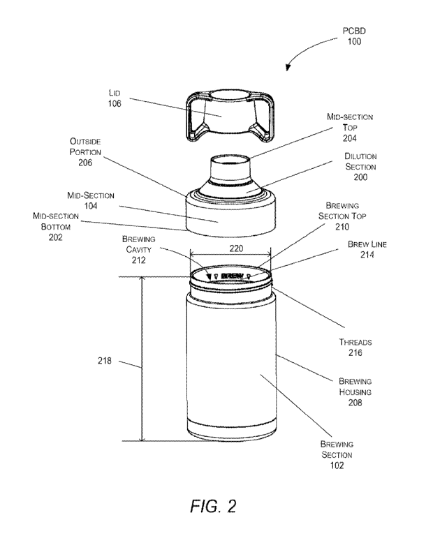
10009] FIG. 2 is an exploded view of the PCBD, shown in FIG. I,
in accordance with the present disclosure.
10010] FIG. 3 is an isometric view of the mid-section of PCBD,
shown in FIGs. 1 and 2, in accordance with the present
disclosure.
11:10111 FIG. 4 is a cut-away front view of the PCBD, shown in
FIG. I, in accordance with the present disclosure.
NOtfl FIG. 5 is a cut-away front view of the brewing section
of the PCBD, shown in FIG. 4, in accordance with the present
disclosure.
[1:101.3] FIG. 6 is a cut-way front view of the combination of the
brewing section and mid-section of the PCBD, shown in FIG. 4,
in accordance with the present disclosure.
10014] FIG. 7 is an isometric view of the PCBD, shown in FIG.
1, draining a filter bag of organic material in accordance with
the present disclosure.
10015] FIG. 8 is a flowchart of a method performed by the PCBD
shown in FIGs. 1 through 3 in accordance with the present
disclosure.
DETAILED DESCRIPTION
10016] Disclosed is a portable cold brewer (PCBD) with drinkware
for brewing a brewed effluent from a filter bag containing an
organic material. The PCBD comprises a brewing section, a mid-
CA 03221705 2023- 12- 6
WO 2022/261680
PCT/US2022/072892
section, and a lid.
The brewing section includes a housing,
where the housing includes a brewing section top and a brewing
cavity within the housing.
The brewing cavity includes an
organic material measure marking and a brew line marking. The
organic material measure marking is configured to measure an
amount of organic material that will fill the filter bag, the
brewing cavity is configured to receive the filter bag
containing the organic material that was measured by the organic
material measure marking, and the brew line marking is
configured to measure an amount of water to fill the brewing
cavity when the filter bag is inserted into the brewing cavity.
The mid-section has a dilution section and a dilution line
marking, where the mid-section is configured to cover the
brewing section top, and the lid is configured to cover the
dilution section. The mid-section has an outside portion and
an inside portion defining a dilution cavity within the dilution
section that is configured to receive the filter bag once the
filter bag is removed from the brewing cavity and the mid-section
is overturned and placed on the brewing section top. The mid-
section is configured to drain the brewed effluent from the
filter bag when the filter bag is in a resting position within
the dilution cavity and the dilution line marking is configured
to measure an additional amount of water to fill the mid-section
when the brewed effluent has drained from the filter bag.
6
CA 03221705 2023- 12- 6
WO 2022/261680
PCT/US2022/072892
10047] As disclosed is a method for cold brewing the brewed
effluent from the filter bag containing the organic material in
the PCBD. The method includes filling the brewing section cavity
within the brewing section with the organic material until the
organic material reaches an organic material measuring marking,
filling the filter bag with the organic material from the brewing
section cavity, placing the filter bag within the brewing
section cavity, and adding water to the brewing section cavity
until a water level of the water reaches a brew line marking
within the brewing cavity. The method further includes placing
the mid-section on the top of the brewing section, placing the
lid on the top of the outside portion of the mid-section, and
cold brewing the brewed effluent from the filter bag containing
the organic material within the brewing section. The method
then includes removing the lid from the top of the outside
portion of the mid-section, removing the mid-section, removing
the filter bag from the brewing section cavity, overturning the
mid-section such that the outside portion rests on the top of
the brewing cavity, placing the filter bag within the dilution
cavity of the mid-section, and draining the brewed effluent from
the filter bag into the brewing section cavity of the brewing
section through the dilution section.
10018] In this example, the PCBD is a portable eco-friendly
product that can be used as both a brewing vessel and insulated
7
CA 03221705 2023- 12- 6
WO 2022/261680
PCT/US2022/072892
drinkware. The PCBD may be used to cold brew organic material
such as, for example, coffee or tea. The organic material may
be placed in a filter bag and/or sachet. As an alternative,
pre-filled sachet of organic material may be utilized instead
of the filter bag.
10049]
In general, the PCBD may be designed and engineered for
optimal thermal performance utilizing material such as, for
example, double-wall vacuum insulated brew chamber, double wall
vacuum insulated dilution section, and a foam insulated lid.
With these types of materials (or other equivalent materials)
the PCBD may be designed to keep an effluent liquid of cold brew
cold all day. As an example, the external portions of the PCBD
may be constructed of plastic, hard rubber, glass, ceramic, or
metal such as, for example, high quality, food safe 18/8
stainless steel.
All of the seals and a filter tie may be
constructed from durable and long-lasting food grade silicone.
The PCBD is dishwasher safe; easily cleanable (having full-width
threads to allow the PCBD to separate into the brewing section,
mid-section, and lid); eco-friendly since it eliminates single
use cups and uses compostable filter media and a reusable
silicone filter tie; easy to use with no measuring required
(i.e., utilizing brew and fill lines); easily carriable with a
lid that has dual loops for securing with carabiner, etc.
8
CA 03221705 2023- 12- 6
WO 2022/261680
PCT/US2022/072892
10020]
Turning to FIG. 1, a front view of an example of an
implementation of the PCBD 100 is shown in accordance with the
present disclosure.
The PCBD 100 includes a brewing section
102, mid-section 104, and lid 106.
10021]
in .L1G. 2, an exploded view of the PCBD 100 is shown in
accordance with the present disclosure. In this view, the mid-
section 104 includes a dilution section 200, a mid-section
bottom 202, mid-section top 204, outside portion 206, and an
inside portion (not shown in this view). The brewing section
102 includes a housing 206 having a brewing top 210 defining an
opening into the top of the brewing section 102, a brewing cavity
212 within the brewing section 102, a brew line 214 within the
brewing cavity 212, and a first set of threads 216 on the outside
of the housing 208 near the brewing section top 210. In this
example, the brewing housing 208 may be a cylindrical housing
constructed of plastic, hard rubber, glass, ceramic, or metal.
As an example, the housing 208 may have a height 218 of
approximately 178 millimeters and the brewing section top 210
may have a diameter 220 of approximately 85 millimeters.
10022]
In FIG. 3, an isometric view of the mid-section 104 of
the PCBD 100 is shown in accordance with the present disclosure.
The dilution section 200 is shown to include a fill line 300 and
a set of threads 302 at the mid-section top 204.
In this
example, the dilution section 200 includes an inside portion
9
CA 03221705 2023- 12- 6
WO 2022/261680
PCT/US2022/072892
defining a dilution cavity within the dilution section 200. The
inside portion may include a concave surface that acts as a
funnel.
10023]
FIG. 4 is a cut-away front view of the PCBD 100 in
accordance with the present disclosure. In this example, the
brewing section 102 may include the brew line 214, a vacuum
chamber 400, vacuum cap 402, and vacuum seal 404.
The mid-
section 104 may include a silicone seal 406, vacuum chamber 408,
a vacuum seal 410, silicone cap 412, and the fill line 300. The
Lid 106 may include a foam insulation 414 and a plastic cap 416.
10024]
In this example, the brewing section 102 comprises the
housing 208 that includes the brewing section top 210 and brewing
cavity 212 within the housing 208. In this example, the brewing
cavity 212 includes one or more organic material measurement
markings 418 and the brew line 214 marking. The one or more
organic material measurement markings 418 are marking to
indicate to a user the amount of organic material that should
be poured into the brewing cavity 212 to properly brew the
organic material. This organic material will then be pound into
the filter bag to fill the filter bag by proper amount need to
brew the organic material. In this example, the organic material
may be coffee or tea and, as an example, a first organic material
measure marking, of the one or more organic material measurement
markings 418, may be for use with tea while the other organic
CA 03221705 2023- 12- 6
WO 2022/261680
PCT/US2022/072892
material measure marking may be for use with coffee.
Alternatively, the first organic material measure marking, of
the one or more organic material measurement markings 418, may
be light roast coffee or tea and the other organic material
measure marking may be for used for dark roast coffee or tea.
As an example, the first organic material measure marking may
be located at a height 420 of 36 millimeters from a brewing
section bottom 422 of the brewing section 102. The brew line
214 is configured to measure an amount of water to pour into the
brewing cavity 212 when the filter bag is inserted into the
brewing cavity 212. As an example, the brew line 214 may be
located at a height 424 of 142 millimeters from a brewing section
bottom 422 of the brewing section 102.
10025] Moreover, in this example, the mid-section 104 includes
the outside portion 206 and an inside portion defining a dilution
cavity 426 within the dilution section, wherein the dilution
section is configured to receive the filter bag once the filter
bag is removed from the brewing cavity 212 and the mid-section
104 is overturned (i.e., flipped over) and placed on the brewing
section top 210. The mid-section 104 includes the dilution line
300 and the mid-section 104 also includes a set of threads 428
on the inside portion of the mid-section 104. In this example,
the dilution line 300 marking is configured to measure an
11
CA 03221705 2023- 12- 6
WO 2022/261680
PCT/US2022/072892
additional amount of water to fill the mid-section 104 when the
brewed effluent has drained from the filter bag.
10026]
In this example, the brewing section top 210 of the
housing 208 includes the first set of threads 216 and the mid-
section bottom includes the second set of threads 428 within the
inside portion of the mid-section 104 configured to physically
interface with the first set of threads 216 of the brewing
section top 210. The inside portion of the mid-section 104 is
configured to be removably attached to the brewing section top
210 by attaching the second set of threads 428 to the first set
of threads 216 to form a watertight seal between the brewing
section 102 and the mid-section 104.
1101027] Additionally, the mid-section 104 includes the mid-
section top 204 above the dilution cavity 426 and the third set
of threads 302 within the inside portion of the mid-section 104
at the mid-section top 204. The lid 106 includes a fourth set
of threads 440 that are configured to physically interface with
the third set of threads 302 of the mid-section 104. In this
example, the lid is configured to be removably attached to the
mid-section top 204 by attaching the fourth set of threads 440
to the third set of threads 302 to form a watertight seal between
the mid-section top 204 and the lid 106.
In this example, the
lid 106 may include a lid handle that may be the plastic cap
416.
12
CA 03221705 2023- 12- 6
WO 2022/261680
PCT/US2022/072892
10028]
FIG. 5 is a cut-away front view of the brewing section
102 in accordance with the present disclosure.
In FIG. 6, a
cut-way front view of the combination of the brewing section 102
and mid-section 104 is shown in accordance with the present
disclosure. In these views, the one or more organic material
measurement markings 418 and brew line 214 are shown within the
inside wall of the cavity within the brewing section 102.
Additionally, the dilution/fill line 300 is shown along the
inside wall of the dilution section 200 of the mid-section 104.
10029]
FIG. 7 is an isometric view of the PCBD 100 draining a
filter bag 700 of organic material in accordance with the present
disclosure. The method for brewing the filter bag 700 will be
described below. In general, the method is process that includes
the following steps.
10030]
In the first step, if organic material is not pre-
packaged in a cold brew sachet (i.e., a pre-packaged filter bag
700), the organic material may be measured by utilizing the one
or more organic material measurement markings 418 within the
walls of inner cavity of the brewing section 102. There may be
multiple lines for the one or more organic material measurement
markings 418 because there is generally a volumetric difference
between the equal weights of dark roast coffee, light roast
coffee, or tea. As such, the organic material may be poured
into the brewing section 102 and compared against the different
13
CA 03221705 2023- 12- 6
WO 2022/261680
PCT/US2022/072892
lines of the one or more organic material measurement markings
418 to determine the proper amount of organic material to use.
Once measured, the organic material may be poured out of the
brewing section 102 into the filter bag 700 that may have its
top secured by a filter tie 702.
The filter bag 700 is then
placed into the cavity of the brewing section 102 and cavity is
filled with water until the water level reaches the brewing line
214. The mid-section 104 and lid 106 are then placed on and the
organic material is allowed to brew for a certain period of
time, for example, 12 to 24 hours.
10031]
In the second step, the mid-section 104 is removed and
the filter bag 700 is extracted from the cavity of the brewing
section 102. The mid-section 104 is then inverted and placed
on the top of the brewing section 102 and filter bag 700 is
placed on the inside of the inverted mid-section 104 (i.e., on
the dilution section 200) and allowed to drain out of the filter
bag 700 into the effluent liquid in the cavity of the brewing
section 102.
10032]
In this third step, the filter bag 700 is removed and
ice, flavorings, dairy, or diary alternatives may be added via
the dilution section 200. Once these additions are added, the
mid-section 104 is removed, inverted, and re-installed on the
top of the brewing section 102. Water may then be added to the
PCBD 100 to the final dilution line (i.e., dilution/fill line
14
CA 03221705 2023- 12- 6
WO 2022/261680
PCT/US2022/072892
300). The lid 106 is then placed on the top of the mid-section
104 and the process is complete.
10033] In this example, it is appreciated by those of ordinary
skill in the art that instead of utilizing a filter bag with the
organic material, pre-filled and sealed coffee or tea sachets
may also be utilized.
10034] FIG. 8 is a flowchart of a method performed by the PCBD
100 in accordance with the present disclosure. The method 800
starts filling 802 the brewing section cavity with the organic
material until the organic material reaches the organic material
measuring marking; measuring 803 the amount of organic material
with the organic material measuring marking; pouring 804 the
filter bag with the organic material from the brewing section
cavity; pouring 804 out the organic material into the filter bag
700; placing 806 the filter bag within the cavity of the brewing
section 102; filling 808 the cavity of the brewing section 102
with water until the water level reaches the brew line 214;
placing 810 a mid-section on top of the brewing section, wherein
the mid-section 104 includes a dilution section 200, an outside
portion, and an inside portion having a recess; placing 812 a
lid on top of the outside portion of the mid-section 104; cold
brewing 814 a brewed effluent from the filter bag 700 containing
the organic material; removing 816 the lid from the top of the
outside portion of the mid-section 104; removing 818 the mid-
CA 03221705 2023- 12- 6
WO 2022/261680
PCT/US2022/072892
section 104; removing 820 the filter bag 700 from the cavity of
the brewing section 102; overturning (i.e., flipping) 822 the
mid-section 104 such that the outside portion rests on the top
of the brewing section 102; placing 824 the filter bag 700 on
the dilution section 200 of the mid-section 104; draining 826
the brewed effluent from the filter bag 700 into the cavity of
the brewing section 102 through the dilution section 200;
removing 828 filter bag 700; adding 829 ice and/or condiments
(such as, for example, dairy, dairy alternatives, sweeteners,
or flavorings); placing 330 the mid-section 104 back on top of
the brewing section 102; filling 832 the PCBD 100 with water
until the water level reaches the dilution line 300; and placing
834 the lid 106 on the mid-section 104. The method then ends.
10035]
It will be understood that various aspects or details of
the disclosure may be changed without departing from the scope
of the disclosure. It is not exhaustive and does not limit the
claimed disclosures to the precise form disclosed. Furthermore,
the foregoing description is for the purpose of illustration
only, and not for the purpose of limitation. Modifications and
variations are possible in light of the above description or may
be acquired from practicing the disclosure.
The claims and
their equivalents define the scope of the disclosure. Moreover,
although the techniques have been described in language specific
to structural features and/or methodological acts, it is to be
16
CA 03221705 2023- 12- 6
WO 2022/261680
PCT/US2022/072892
understood that the appended claims are not necessarily limited
to the features or acts described.
Rather, the features and
acts are described as example implementations of such
techniques.
10036]
Furthermore, the description of the different examples
of implementations has been presented for purposes of
illustration and description, and is not intended to be
exhaustive or limited to the examples in the form disclosed.
Many modifications and variations will be apparent to those of
ordinary skill in the art.
Further, different examples of
implementations may provide different features as compared to
other desirable examples. The example, or examples, selected
are chosen and described in order to best explain the principles
of the examples, the practical application, and to enable others
of ordinary skill in the art to understand the disclosure for
various examples with various modifications as are suited to the
particular use contemplated.
10037] It will also be understood that various aspects or
details of the invention may be changed without departing from
the scope of the invention. It is not exhaustive and does not
limit the claimed inventions to the precise form disclosed.
Furthermore, the foregoing description is for the purpose of
illustration only, and not for the purpose of limitation.
Modifications and variations are possible in light of the above
17
CA 03221705 2023- 12- 6
WO 2022/261680
PCT/US2022/072892
description or may be acquired from practicing the invention.
The claims and their equivalents define the scope of the
invention.
10038] In some alternative examples of implementations, the
function or functions noted in the blocks may occur out of the
order noted in the figures.
For example, in some cases, two
blocks shown in succession may be executed substantially
concurrently, or the blocks may sometimes be performed in the
reverse order, depending upon the functionality involved. Also,
other blocks may be added in addition to the illustrated blocks
in a flowchart or block diagram.
10039] The description of the different examples of
implementations has been presented for purposes of illustration
and description, and is not intended to be exhaustive or limited
to the examples in the form disclosed. Many modifications and
variations will be apparent to those of ordinary skill in the
art. Further, different examples of implementations may provide
different features as compared to other desirable examples. The
example, or examples, selected are chosen and described in order
to best explain the principles of the examples, the practical
application, and to enable others of ordinary skill in the art
to understand the disclosure for various examples with various
modifications as are suited to the particular use contemplated.
18
CA 03221705 2023- 12- 6