Note: Descriptions are shown in the official language in which they were submitted.
CA 03222151 2023-11-30
WO 2022/256592 PCT/US2022/032061
FINE FIBER INSULATION PRODUCTS
WITH IMPROVED THERMAL PROPERTIES
RELATED APPLICATION(S)
[0001] This application claims priority to and any benefit of U.S. Provisional
Application
No. 63/196,890, filed June 4, 2021, the content of which is incorporated
herein by reference in
its entirety.
FIELD
[0002] The present application generally relates to fiberglass insulation
products, and more
particularly, to fiberglass insulation products with improved performance
properties.
BACKGROUND
[0003] The term "fibrous insulation product" encompasses a variety of
compositions, articles
of manufacture, and manufacturing processes. Mineral fibers, such as glass
fibers, are
commonly used in insulation products and nonwoven mats. Fibrous insulation is
typically
manufactured by fiberizing a molten composition of polymer, glass, or other
mineral fibers
from a fiberizing apparatus, such as a rotating spinner. To form an insulation
product, fibers
produced by the rotating spinner are drawn downwardly from the spinner towards
a conveyor
by a blower. As the fibers move downward, a binder composition is sprayed onto
the fibers
and the fibers are collected into a high loft, continuous blanket on the
conveyor. The fiber-
binder matrix gives the insulation product resiliency for recovery after
packaging and provides
stiffness and handleability so that the insulation product can be handled and
applied as needed
in the insulation cavities of buildings. The binder composition also provides
protection to the
fibers from interfilament abrasion and promotes compatibility between the
individual fibers.
[0004] The blanket containing the binder-coated fibers is then passed through
a curing oven
and the binder is cured to set the blanket to a desired thickness. After the
binder composition
has cured, the fiber insulation may be cut into lengths to form individual
insulation products,
and the insulation products may be packaged for shipping to customer
locations. One typical
insulation product produced is an insulation batt or blanket, which is
suitable for use as cavity
(e.g., wall, floor, ceiling) insulation in residential dwellings or other
buildings, and which might
also be used to insulate an attic or other portions of a building. Such a batt
or blanket is typically
a unitary structure that may be relatively flexible or rollable. Another
common insulation
product is air-blown or loose-fill insulation, which is suitable for use as
sidewall and attic
1
CA 03222151 2023-11-30
WO 2022/256592 PCT/US2022/032061
insulation in residential and commercial buildings as well as in hard-to-reach
locations. Such
loose-fill insulation is often formed as many relatively small discrete
pieces, tufts, or the like,
which may or may not have a binder applied thereto. Loose-fill insulation can
also be formed
of small cubes that are cut from insulation blankets, compressed, and packaged
in bags.
[0005] The insulating performance of a thermal insulation material is mainly
determined by
the ratio of the material's thickness divided by its thermal conductivity (k),
which measures
the amount of heat (in BTUs per hour) that will be transmitted through one
square foot of 1-
inch thick insulation in order to cause the temperature to rise or fall one
degree from one side
of the insulation to the other. The higher the thickness, and the lower the k-
value, the better the
insulating performance of the material.
[0006] Fibrous insulation for building products requires low thermal
conductivity to be an
effective insulator in wall and ceiling cavities. It is also desirable to
reduce overall product
weight, although generally, reducing product weight negatively impacts thermal
performance.
Particularly, attempts have been made to reduce product weight by reducing the
diameter of
the fibers used to form the fibrous insulation products, which conventionally
have an average
fiber diameter of about 4 microns (with 1 micron being equal to 3.94 hundred
thousandths of
an inch or HT) or more.
[0007] However, such a reduction of fiber diameter has traditionally been
found to negatively
impact the insulation value (R-value) of a product at a particular area weight
and product
thickness. Thus, reducing the average fiber diameter of an insulation product
below 4 microns
has previously not been practical, as such products were unable to meet
performance
requirements while still being economical. Accordingly, there is an unmet need
for insulation
products formed from fibers thinner than 4 microns that effectively meet the
necessary
performance requirements, such as thermal performance, and may also improve
overall
material efficiency.
SUMMARY
[0008] Various aspects of the present inventive concepts are directed to an
insulation product
comprising a plurality of glass fibers; and a cross-linked formaldehyde-free
binder composition
at least partially coating the glass fibers, wherein the insulation product
has a length, a width,
and a thickness, with the length being greater than each of the width and the
thickness. The
glass fibers have an average fiber diameter in the range of 8 HT (2.03 pm) to
15 HT (3.81 pm),
including the range of 12 HT (3.05 pm) to 14.5 HT (3.68 pm).
2
CA 03222151 2023-11-30
WO 2022/256592 PCT/US2022/032061
[0009] In any of the exemplary embodiments disclosed herein, at a density (x)
between 0.2 pcf
and 1.6 pcf, the insulation product may achieve a thermal conductivity (k-
value) (y), expressed
as BTU-in/(hr.ft2. F), less than or equal to that which satisfies Formula
(III):
Formula (III): y = 0.116x2 - 0.3002x + 0.4219.
[0010] In some exemplary embodiments the thermal conductivity (k-value) (y) of
the
insulation product is less than 0.3 BTU-in/(hr.ft2. F). In any of the
exemplary embodiments
disclosed herein, at a density (x) between 0.3 pcf and 1.35 pcf, the
insulation product achieves
a thermal conductivity (k-value) (y), expressed as BTU-in/(hr.ft2. F), within
5% of a value (y)
that satisfies Formula (II):
Formula (II): y = 0.1013x2 - 0.2438x + 0.3763.
[0011] In any of the exemplary embodiments disclosed herein, the insulation
product may have
a density (x) in the range of 0.5 pcf to 1.3 pcf, including between 0.7 pcf
and 1.0 pcf.
[0012] In any of the exemplary embodiments disclosed herein, the insulation
product may
comprise a length, a width, and a thickness, with the length being greater
than each of the width
and the thickness, and wherein at least 30% by weight of the glass fibers are
oriented within
+/- 15 of a plane parallel to the length of the insulation product.
[0013] In some exemplary embodiments, at least 15% by weight of the glass
fibers in the
insulation product are at least partially bound in a substantially parallel
orientation with at least
one other glass fiber in the insulation product.
[0014] In any of the exemplary embodiments, prior to crosslinking, the
formaldehyde-free
binder composition comprises at least one monomeric polyol and polycarboxylic
acid in a
combined amount of at least 45% by weight, based on a total weight of the
binder composition.
Additionally, the uncross-linked binder composition may have a pH in the range
of 2 to 5.
[0015] Further exemplary embodiments are directed to a low-density residential
insulation batt
comprising a plurality of glass fibers having an average fiber diameter in the
range of 8 HT
(2.03 1.tm) and 15 HT (3.81 1.tm) and a cross-linked formaldehyde-free binder
composition at
least partially coating the glass fibers, wherein at least 15 wt.% of the
glass fibers in the
insulation batt are at least partially bound in a substantially parallel
orientation with at least one
other glass fiber in the insulation batt. The insulation batt, at a density
(x) between 0.2 pcf and
1.6 pcf, achieves a thermal conductivity (k-value) (y), expressed as BTU-
in/(hr=ft2. F), within
5% of a value (y) that satisfies Formula (II):
Formula (II): y = 0.1013x2 - 0.2438x + 0.3763.
3
CA 03222151 2023-11-30
WO 2022/256592 PCT/US2022/032061
[0016] Moreover, in any of the exemplary embodiments, the insulation batt, at
a density (x)
between 0.2 pcf and 1.6 pcf, may achieve a thermal conductivity (k-value) (y),
expressed as
BTU-in/(hr=ft2. F), less than or equal to that which satisfies Formula (III):
Formula (III): y = 0.116x2 - 0.3002x + 0.4219.
[0017] In these or other exemplary embodiments, the insulation batt has a
thermal conductivity
(y) no greater than 0.5 BTU-in/(hr=ft2. F), or in some embodiments, no greater
than 0.3 BTU-
in/(hr=ft2. F).
[0018] In any of the exemplary embodiments, the insulation batt comprises a
length, a width,
and a thickness, with the length being greater than each of the width and the
thickness, and at
least 30% by weight of the glass fibers are oriented within +/- 15 of a plane
parallel to the
length of the insulation batt. The glass fibers may be oriented such that no
more than 35% by
weight of the binder composition is present in the form of a gusset.
[0019] Yet further exemplary embodiments are directed to an insulation product
comprising a
plurality of glass fibers having an average fiber diameter of less than or
equal to 15 HT (3.81
1.tm) and a cross-linked formaldehyde-free binder composition. The insulation
product has a
length, a width, and a thickness, with the length being greater than each of
the width and the
thickness. At least 30% by weight of the glass fibers in the insulation
product are oriented
within +/- 15 of a common plane defined by the length and width of the
insulation product.
The fibrous insulation product, at an R-value in the range of R20 to R24 and a
thermal
conductivity (k-value) less than 0.35 BTU-in/(hr.ft2. F), has a density (x),
when uncompressed,
that is at least 7% lower than an otherwise comparable insulation product
comprising glass
fibers having an average fiber diameter of greater than 15 HT (3.81 1.tm), at
a consistent R-
value and k-value.
[0020] In these or other exemplary embodiments, the insulation product has a
density (x) that
is between 0.5 pcf and 1.35 pcf and achieves a thermal conductivity (y) less
than or equal to
that which satisfies Formula (III):
Formula (III): y = 0.116x2 - 0.3002x + 0.4219.
[0021] Yet further exemplary embodiments are directed to a method of forming
an insulation
product. The method comprises fiberizing molten glass into a plurality of
glass fibers, coating
the glass fibers with an aqueous, formaldehyde-free binder composition,
randomly depositing
the glass fibers onto a moving conveyor, forming an uncured fiberglass
blanket, and passing
the uncured fiberglass blanket through a curing oven to cross-link the binder
composition and
form the insulation product. The insulation product comprises a length, a
width, and a
thickness, with the length being greater than each of the width and the
thickness.
4
CA 03222151 2023-11-30
WO 2022/256592 PCT/US2022/032061
[0022] The glass fibers have an average fiber diameter in a range of 8 HT
(2.03 1.tm) to 15 HT
(3.8111m) and the insulation product may have a binder content (LOT) of less
than or equal to
8% by weight. In some exemplary embodiments, the insulation product has a
density (x)
between 0.2 pcf and 1.6 pcf and achieves a thermal conductivity (k-value) (y),
expressed as
BTU-in/(hr=ft2. F), less than that which satisfies Formula (III):
Formula (III): y = 0.116x2 - 0.3002x + 0.4219.
[0023] Yet further exemplary embodiments of the present disclosure are
directed to an
insulation product comprising a plurality of glass fibers having an average
fiber diameter of
less than or equal to 15 HT (3.81 1.tm); and a cross-linked formaldehyde-free
binder
composition at least partially coating the glass fibers. The cross-linked
formaldehyde-free
binder composition may be formed from an aqueous binder composition comprising
at least
one monomeric polyol and the insulation product may have a binder content
(LOT) of less than
or equal to 8% by weight. The insulation product has an R-value in the range
of 19 to 24, a
thickness between 5.0 inches and 7.0 inches, and a k-value between 0.20 and
0.35 BTU-
in/(hr=ft2. F). Additionally, the insulation product has a density, when
uncompressed, that is at
least 30% lower than an otherwise comparable insulation product comprising a
binder
composition that includes a polymeric polyol.
BRIEF DESCRIPTION OF THE DRAWINGS
[0024] Features and advantages of the present invention will become apparent
to those of
ordinary skill in the art to which the invention pertains from a reading of
the following
description together with the accompanying drawings, in which:
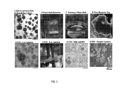
[0025] FIG. 1 is a perspective view of an exemplary embodiment of a fibrous
insulation
product;
[0026] FIG. 2 is an elevational view of an exemplary embodiment of a
manufacturing line
for producing the fibrous insulation product of FIG. 1;
[0027] FIG. 3 is a scanning electron microscope ("SEM") image illustrating a
section of an
exemplary fibrous insulation product formed with glass fibers having an
average fiber diameter
of 14.5 HT;
[0028] FIG. 4 is an SEM image illustrating a section of an exemplary fibrous
insulation
product formed with glass fibers having an average fiber diameter of 14.5 HT;
[0029] FIG. 5 is an SEM image illustrating a section of a conventional fibrous
insulation
product formed with glass fibers having an average fiber diameter of 16.7 HT
and an insulation
value of R-21;
CA 03222151 2023-11-30
WO 2022/256592 PCT/US2022/032061
[0030] FIG. 6 is a graphical representation of the fiber orientation
distribution within +/- 15
of a plane parallel to the product length Li (0 ) taken from the cross-section
along the machine
direction of an exemplary fibrous insulation product formed with glass fibers
having an average
fiber diameter of 14.5 HT;
[0031] FIG. 7 is a graphical representation of the fiber orientation
distribution within +/- 30
of a plane parallel to the product length Li (0 ) taken from the cross-section
along the machine
direction of an exemplary fibrous insulation product formed with glass fibers
having an average
fiber diameter of 14.5 HT;
[0032] FIG. 8 is a graphical representation of the fiber orientation
distribution within +/- 50
of a plane parallel to the product length Li (0 ) taken from the cross-section
along the machine
direction of an exemplary fibrous insulation product formed with glass fibers
having an average
fiber diameter of 14.5 HT;
[0033] FIG. 9(a) is an SEM image illustrating the fiber orientation of a 24 mm
x 16 mm
section of an exemplary fine fiber insulation product formed with glass fibers
having an
average fiber diameter of about 14 HT.
[0034] FIG. 9(b) is a graphical representation of the fiber orientation
distribution curve
(measured in degrees, based on a plane parallel to the product length Li (0 )
taken from the
cross-section along the machine direction of the fibrous insulation product of
FIG. 9(a);
[0035] FIG. 10(a) is an SEM image illustrating the fiber orientation of a 24
mm x 16 mm
section of an exemplary fine fiber insulation product formed with glass fibers
having an
average fiber diameter of about 14 HT.
[0036] FIG. 10(b) is a graphical representation of the fiber orientation
distribution curve
(measured in degrees, based on a plane parallel to the product length Li (0 )
taken from the
cross-section along the machine direction of the fibrous insulation product of
FIG. 10(a);
[0037] FIGS. 11(a)-11(c) are SEM images showing parallel fiber bundles present
in an
exemplary fibrous insulation product formed with glass fibers having an
average fiber diameter
of 14.5 HT;
[0038] FIGS. 12(a)-12(c) are SEM images showing parallel fiber bundles present
in an
exemplary fibrous insulation product formed with glass fibers having an
average fiber diameter
of 14.5 HT;
[0039] FIGS. 13(a)-13(b) are SEM images showing binder gussets present in an
exemplary
fibrous insulation product formed with glass fibers having an average fiber
diameter of 14.5
HT;
6
CA 03222151 2023-11-30
WO 2022/256592 PCT/US2022/032061
[0040] FIG. 14 graphically illustrates a predicted thermal conductivity (k-
value) curve per
product density compared to an actual thermal conductivity (k-value) curve per
product
density;
[0041] FIG. 15 graphically illustrates a predicted material efficiency curve
per product
density compared to an actual material efficiency curve per product density;
and
[0042] FIG. 16 graphically illustrates a predicted material efficiency curve
per product
density compared to an adjusted material efficiency curve per product density.
DETAILED DESCRIPTION
[0043] Unless otherwise defined, all technical and scientific terms used
herein have the same
meaning as commonly understood by one of ordinary skill in the art to which
these exemplary
embodiments belong. The terminology used in the description herein is for
describing
exemplary embodiments only and is not intended to be limiting of the exemplary
embodiments.
Accordingly, the general inventive concepts are not intended to be limited to
the specific
embodiments illustrated herein. Although other methods and materials similar
or equivalent to
those described herein can be used in the practice or testing of the present
invention, the
preferred methods and materials are described herein.
[0044] As used in the specification and the appended claims, the singular
forms "a," "an,"
and "the" are intended to include the plural forms as well, unless the context
clearly indicates
otherwise.
[0045] Unless otherwise indicated, all numbers expressing quantities of
ingredients,
chemical and molecular properties, reaction conditions, and so forth, as well
as physical and
measured attributes, used in the specification and claims are to be understood
as being modified
in all instances by the term "about." Accordingly, unless indicated to the
contrary, the
numerical parameters set forth in the specification and attached claims are
approximations that
may vary depending upon the desired properties sought to be obtained by the
present exemplary
embodiments. At the very least each numerical parameter should be construed in
light of the
number of significant digits and ordinary rounding approaches.
[0046] Unless otherwise indicated, any element, property, feature, or
combination of
elements, properties, and features, may be used in any embodiment disclosed
herein, regardless
of whether the element, property, feature, or combination of elements,
properties, and features
was explicitly disclosed in the embodiment. It will be readily understood that
features described
in relation to any particular aspect described herein may be applicable to
other aspects
described herein provided the features are compatible with that aspect. In
particular: features
7
CA 03222151 2023-11-30
WO 2022/256592 PCT/US2022/032061
described herein in relation to the method may be applicable to the fibrous
product and vice
versa; features described herein in relation to the method may be applicable
to the aqueous
binder composition and vice versa; and features described herein in relation
to the fibrous
product may be applicable to the aqueous binder composition and vice versa.
[0047] Notwithstanding that the numerical ranges and parameters setting forth
the broad
scope of the exemplary embodiments are approximations, the numerical values
set forth in the
specific examples are reported as precisely as possible. Any numerical value,
however,
inherently contains certain errors necessarily resulting from the standard
deviation found in
their respective testing measurements. Every numerical range given throughout
this
specification and claims will include every narrower numerical range that
falls within such
broader numerical range, as if such narrower numerical ranges were all
expressly written
herein.
[0048] As used herein, the terms "binder composition," "aqueous binder
composition,"
"binder formulation," "binder," and "binder system' may be used
interchangeably and are
synonymous. Additionally, as used herein, the terms "formaldehyde-free" or "no
added
formaldehyde" may be used interchangeably and are synonymous.
[0049] All numerical ranges are understood to include all possible incremental
sub-ranges
within the outer boundaries of the range. Thus, for example, a density range
of 0.2 pcf to 2.0
pcf discloses, for example, 0.5 pcf to 1.2 pcf, 0.7 pcf to 1.0 pcf, etc.
[0050] By "substantially free" it is meant that a composition includes less
than 1.0% by
weight of the recited component, including no greater than 0.8% by weight, no
greater than
0.6% by weight, no greater than 0.4% by weight, no greater than 0.2% by
weight, no greater
than 0.1% by weight, no greater than 0.5% by weight, and no greater than 0.01%
by weight.
[0051] As used herein, the unit "pounds" or "lb" refers to pounds-mass.
[0052] The present disclosure relates to fiberglass insulation products formed
with fine
diameter glass fibers (i.e., fibers having an average fiber diameter less than
or equal to 15 HT)
to achieve a more favorable fiber orientation and product structure. The
fiberglass insulation
products demonstrate surprisingly improved thermal performance and overall
material
efficiency.
[0053] The fibrous insulation products of the present disclosure comprise a
plurality of
fibers, such as organic or inorganic fibers. In certain exemplary embodiments,
the plurality of
fibers are inorganic fibers, including, but not limited to glass fibers, glass
wool fibers, mineral
wool fibers, slag wool fibers, stone wool fibers, ceramic fibers, metal
fibers, and combinations
thereof.
8
CA 03222151 2023-11-30
WO 2022/256592 PCT/US2022/032061
[0054] Optionally, the fibers may comprise natural fibers and/or synthetic
fibers such as
carbon, polyester, polyethylene, polyethylene terephthalate, polypropylene,
polyamide,
aramid, and/or polyaramid fibers. The term "natural fiber" as used herein
refers to plant fibers
extracted from any part of a plant, including, but not limited to, the stem,
seeds, leaves, roots,
or phloem. Examples of natural fibers suitable for use in the insulation
products include wood
fibers, cellulosic fibers, straw, wood chips, wood strands, cotton, jute,
bamboo, ramie, bagasse,
hemp, coir, linen, kenaf, sisal, flax, henequen, and combinations thereof The
fibrous insulation
products may be formed entirely of one type of fiber, or they may be formed of
a combination
of types of fibers. For example, the fibrous insulation products may be formed
of combinations
of various types of glass fibers or various combinations of different
inorganic fibers and/or
natural fibers depending on the desired application. In any of the embodiments
disclosed
herein, the insulation products may be formed substantially of or entirely of
glass fibers.
[0055] The fibrous insulation products utilize glass fibers having a smaller
diameter than the
glass fibers used in conventional fiberglass insulation products, particularly
residential
insulation products that typically have an average fiber diameter greater than
4 [tm (15.7 HT),
such as 16 HT or 18 HT. In particular, the exemplary fibrous insulation
products disclosed or
suggested herein may include glass fibers having an average fiber diameter,
prior to the
application of the binder composition, equal to or less than 3.81 [tm (15 HT),
including average
fiber diameters no greater than 3.76 [tm (14.8 HT), no greater than 3.68 [tm
(14.5 HT), no
greater than 3.61 [tm (14.2 HT), no greater than 3.56 [tm (14 HT), no greater
than 3.43 [tm
(13.5 HT), no greater than 3.30 [tm (13 HT), no greater than 3.18 [tm (12.5
HT), and no greater
than 3.05 [tm (12 HT). In any of the exemplary embodiments, the fibrous
insulation product
may include glass fibers having an average fiber diameter in the range of 3.05
[tm (12.0 HT)
to 3.81 [tm (15.0 HT), or in the range of 3.30 [tm (13.0 HT) to 3.76 [tm (14.8
HT), or in the
range of 3.43 [tm (13.5 HT) to 3.61 [tm (14.2 HT). In other exemplary
embodiments, the
insulation product may include glass fibers having an average fiber diameter
in the range of
2.03 [tm (8.0 HT) to 3.05 [tm (12.0 HT), or in the range of 2.29 [tm (9.0 HT)
to 2.79 [tm (11.0
HT), or in the range of 2.03 [tm (8.0 HT) to 2.54 [tm (10.0 HT).
[0056] An exemplary procedure used to measure the diameters of the glass
fibers utilizes a
scanning electron microscope (SEM) to directly measure fiber diameter. In
general, a specimen
of the fibrous insulation product is heated to remove any organic materials
(e.g., binder
composition) therefrom, the glass fibers from the specimen are then reduced in
length and
photographed by the SEM. The diameters of the fibers are then measured from
the saved
images by image processing software associated with the SEM.
9
CA 03222151 2023-11-30
WO 2022/256592 PCT/US2022/032061
[0057] More specifically, a specimen of the fibrous insulation product is
heated to 800 F for
a minimum of 30 minutes. The specimen may be heated longer if required to
ensure removal
of any organic materials. The specimen is then cooled to room temperature and
the glass fibers
are reduced in length in order to fit onto an SEM planchette. The glass fibers
may be reduced
in length by any suitable method, such as for example, cut by scissors,
chopped by a razor
blade, or ground in a mortar and pestle. The glass fibers are then adhered to
the surface of the
SEM planchette such that the fibers are not overlapping or spaced too far
apart.
[0058] Once the specimen is prepared for imaging, the specimen is mounted in
the SEM
using normal operating procedures and photographed by the SEM at appropriate
magnification
for the diameter size of the fibers being measured. A sufficient number of
images are collected
and saved to ensure enough fibers are available for measuring. For example, 10
to 13 images
may be required where 250 to 300 individual fibers are being measured. The
fiber diameters
are then measured using an SEM image analysis software program, such as for
example,
Scandium SIS imaging software. An average fiber diameter of the specimen is
then determined
from the number of fibers measured. The fibrous insulation product specimen
may include
glass fibers that are fused together (i.e., two or more fibers joined along
their lengths). For the
purpose of calculating the average fiber diameter of specimens in the present
disclosure, fused
fibers are treated as single fibers.
[0059] An alternative procedure used to measure the average fiber diameter of
the glass
fibers utilizes a device that measures air flow resistance to indirectly
determine the mean or
"effective" fiber diameter of the distributed fibers in a specimen. More
specifically, in one
embodiment of the alternative procedure, a specimen of the fibrous insulation
product is heated
to 800-1,000 F for 30 minutes. The specimen may be heated longer if required
to ensure
removal of any organic materials from the surface of the fibers. The specimen
is then cooled
to room temperature and a test specimen weighing about 7.50 grams is loaded
into the device's
chamber. A constant air flow is applied through the chamber, and once the air
flow has
stabilized, the differential pressure, or pressure drop, through the specimen
is measured by the
device. Based on the air flow and differential pressure measurements, the
device can compute
the average fiber diameter of the specimen.
[0060] The fibrous insulation products of the present disclosure comprise a
formaldehyde-
free or "no added formaldehyde" aqueous binder compositions for use in binding
the inorganic
fibers in the manufacture of the insulation products. The phrase "binder
composition" refers to
organic agents or chemicals, often polymeric resins, used to adhere the
inorganic fibers to one
another in a three-dimensional structure. The binder composition may be in any
form, such as
CA 03222151 2023-11-30
WO 2022/256592 PCT/US2022/032061
a solution, an emulsion, or dispersion. "Binder dispersions" or "binder
emulsions" thus refer
to mixtures of binder chemicals in a medium or vehicle. As used herein, the
terms "binder
composition," "aqueous binder composition," "binder formulation," "binder,"
and "binder
system' may be used interchangeably and are synonymous. Additionally, as used
herein, the
terms "formaldehyde-free" or "no added formaldehyde" may be used
interchangeably and refer
to a binder composition including less than about 1 ppm formaldehyde when
cured or otherwise
dried. The 1 ppm is based on the weight of the product being measured for
formaldehyde
release.
[0061] A wide variety of binder compositions may be used with the glass fibers
of the present
invention. For example, binder compositions fall into two broad, mutually
exclusive classes:
thermoplastic and thermosetting. Both thermoplastic and thermosetting binder
compositions
may be used with the invention. A thermoplastic material may be repeatedly
heated to a
softened or molten state and will return to its former state upon cooling. In
other words, heating
may cause a reversible change in the physical state of a thermoplastic
material (e.g. from solid
to liquid) but it does not undergo any irreversible chemical reaction.
Exemplary thermoplastic
polymers suitable for use in the fibrous insulation product 100 include, but
are not limited to,
polyvinyls (such as polyvinyl acetate, polyvinyl alcohol, polyvinyl butyral,
and the like),
polyethylene terephthalate (PET), polypropylene or polyphenylene sulfide
(PPS), nylon,
polycarbonates, polystyrene, polyamides, polyolefins, acrylic and methacrylic
acid ester resins,
and certain copolymers of polyacrylates.
[0062] In contrast, the term thermosetting polymer refers to a range of
systems which exist
initially as liquids but which, on heating, undergo a reaction to form a
solid, highly crosslinked
matrix. Thus, thermosetting compounds comprise reactant systems, often pairs
of reactants,
that irreversibly crosslink upon heating. When cooled, they do not regain
their former liquid
state but remain irreversibly crosslinked.
[0063] The reactants useful as thermosetting compounds generally have one or
more of
several reactive functional groups: e.g. amine, amide, carboxyl, or hydroxyl.
As used herein,
"thermoset compound" (and its derivative clauses like "thermosetting
compound,"
"thermosetting binder" or "thermoset binder") refers to at least one of such
reactants, it being
understood that two or more may be necessary to form the crosslinking system
characteristic
of thermosetting compounds. In addition to the principle reactants of the
thermosetting
compounds, there may be catalysts, process aids, and other additives.
[0064] One category of thermosetting binders includes a variety of phenol-
aldehyde, urea-
aldehyde, melamine-aldehyde, and other condensation-polymerization materials.
11
CA 03222151 2023-11-30
WO 2022/256592 PCT/US2022/032061
Phenolic/formaldehyde binder compositions are a known thermosetting binder
system and
have hi storically been favored for their low cost and the ability to go from
a low viscosity liquid
in the uncured state to a rigid thermoset polymer when cured.
[0065] Formaldehyde-free, thermosetting binder systems may include those based
on
polycarboxy polymers and a polyol. An example is the polyacrylic
acid/polyol/polyacid binder
system described in U.S. Pat. Nos. 6,884,849 and 6,699,945 to Chen et al., the
entire contents
of which are each expressly incorporated herein by reference. Another example
is the
polymeric polycarboxylic acid/long chain polyol/short chain polyol binder
system described in
U.S. Patent Publ. No. 2019/0106564 to Zhang, et al., the disclosure of which
being fully
incorporated herein by reference. Another example is the polymeric
polycarboxylic acid/
monomeric polyol binder system described in U.S. Provisional Patent
Application No.
63/086,267, the disclosure of which being fully incorporated herein by
reference. Yet another
example is the polycarboxylic acid/polyol/nitrogen-based protective agent
binder system
described in U.S. Provisional Patent Application No. 63/073,013, the
disclosure of which being
fully incorporated herein by reference.
[0066] A second category of formaldehyde-free, thermosetting binder
compositions are
referred to as "bio-based" or "natural" binders. "Bio-based binder" and
"natural binder" are
used interchangeably herein to refer to binder compositions made from nutrient
compounds,
such as carbohydrates, proteins, or fats, which have much reactive
functionality. Because they
are made from nutrient compounds, they are environmentally friendly. Bio-based
binder
compositions are described in more detail in U.S. Pat. Publication No.
2011/0086567 to
Hawkins et al., filed October 8, 2010, the entire contents of which are
expressly incorporated
herein by reference.
[0067] In some exemplary embodiments, the binder includes Owens-Corning's
EcoTouchTm
binder or EcoPureTM binder, Owens Corning's SustainaTM binder, or Knauf s
ECOSE binder.
[0068] Alternative reactants useful as thermosetting compounds are triammonium
citrate-
dextrose systems derived from mixing dextrose monohydrate, anhydrous citric
acid, water and
aqueous ammonia. Additionally, carbohydrate reactants and polyamine reactants
are useful
thermosetting compounds, wherein such thermosetting compounds are described in
more detail
in U.S. Pat. Nos. 8,114,210, 9,505,883 and 9,926,464, the disclosures of which
are hereby
incorporated by reference.
[0069] It has surprisingly been discovered that fibrous insulation products
manufactured
using glass fibers having an average fiber diameter below 15 HT have improved
properties
when manufactured using a formaldehyde-free binder composition comprising a
polyol and a
12
CA 03222151 2023-11-30
WO 2022/256592 PCT/US2022/032061
primary cross-linking agent, such as a polycarboxylic acid or salt thereof
Particularly notable
improvements have been discovered when the polyol included in the binder
composition is a
monomeric polyol.
[0070] The primary crosslinking agent may be any compound suitable for
crosslinking a
polyol. Non-limiting examples of suitable cross-linking agents include
polycarboxylic acid-
based materials having one or more carboxylic acid groups (-COOH), such as
monomeric and
polymeric polycarboxylic acids, including salts or anhydrides thereof, and
mixtures thereof. In
any of the exemplary embodiments, the polycarboxylic acid may be a polymeric
polycarboxylic acid, such as a homopolymer or copolymer of acrylic acid. The
polymeric
polycarboxylic acid may comprise polyacrylic acid (including salts or
anhydrides thereof) and
polyacrylic acid-based resins such as QR-1629S and Acumer 9932, both
commercially
available from The Dow Chemical Company, polyacrylic acid compositions
commercially
from CH Polymer, and polyacrylic acid compositions commercially available from
Coatex.
Acumer 9932 is a polyacrylic acid/sodium hypophosphite resin having a
molecular weight of
about 4,000 and a sodium hypophosphite content of 6-7% by weight, based on the
total weight
of the polyacrylic acid/sodium hypophosphite resin. QR-1629S is a polyacrylic
acid/glycerin
resin composition. Aquaset-529 is a composition containing polyacrylic acid
crosslinked with
glycerol.
[0071] The polycarboxylic acid may comprise a polymeric polycarboxylic acid,
such as
polyacrylic acid, poly(meth)acrylic acid, polymaleic acid, and like polymeric
polycarboxylic
acids, anhydrides, salts, or mixtures thereof, as well as copolymers of
acrylic, methacrylic acid,
maleic acid, and like carboxylic acids, anhydrides, salts, and mixtures
thereof.
[0072] In any of the exemplary embodiments, the polycarboxylic acid may
comprise a
monomeric polycarboxylic acid, such as citric acid, itaconic acid, maleic
acid, fumaric acid,
succinic acid, adipic acid, glutaric acid, tartaric acid, trimellitic acid,
hemimellitic acid, trimesic
acid, tricarballylic acid, and the like, including salts or anhydrides
thereof, and mixtures
thereof.
[0073] The cross-linking agent may, in some instances, be pre-neutralized with
a
neutralization agent. Such neutralization agents may include organic and/or
inorganic bases,
such sodium hydroxide, ammonium hydroxide, and diethylamine, and any kind of
primary,
secondary, or tertiary amine (including alkanol amine). In various exemplary
embodiments,
the neutralization agents may include at least one of sodium hydroxide and
triethanolamine.
[0074] The cross-linking agent is present in the binder composition in at
least 30.0% by
weight, based on the total solids content of the binder composition,
including, without
13
CA 03222151 2023-11-30
WO 2022/256592 PCT/US2022/032061
limitation at least 40% by weight, at least 45% by weight, at least 50% by
weight, at least
52.0% by weight, at least 54.0% by weight, at least 56.0% by weight, at least
58.0% by weight,
and at least 60.0% by weight. In any of embodiments disclosed herein, the
cross-linking agent
may be present in the binder composition in an amount from 30% to 85% by
weight, based on
the total solids content of the aqueous binder composition, including without
limitation 50.0%
to 70.0% by weight, greater than 50% by weight to 65% by weight, 52.0% to
62.0% by weight,
54.0% to 60.0% by weight, and 55.0% to 59.0% by weight.
[0075] Optionally, in addition to, instead of the polycarboxylic acid cross-
linking agent
discussed above, the binder composition may include an amine-based reactant,
such as
ammonium salts (e.g., ammonium salts of a polycarboxylic acid), amines,
diammonium
sulfate, proteins, peptides, amino acids, and the like. Such amine-based
reactants are capable
of participating in a Maillard reaction with a reducing sugar to produce
melanoidins (high
molecular weight, furan ring and nitrogen-containing polymers). Thus, in some
exemplary
embodiments, the binder composition may comprise melanoidins produced by the
reaction of
an amine-based reactant and one or more reducing sugars.
[0076] The aqueous binder composition may further include at least one polyol.
In any of the
exemplary embodiments, the polyol may comprise a monomeric polyol. The
monomeric polyol
may comprise a water-soluble compound having a molecular weight of less than
2,000 Daltons,
including less than 1,000 Daltons, less than 750 Daltons, less than 500
Daltons, and having at
least two hydroxyl (-OH) groups. Exemplary monomeric polyols include glucose,
sucrose,
ethylene glycol, sugar alcohols, pentaerythritol, primary alcohols, 2,2-
bis(methylol)propionic
acid, tri(methylol)propane (TMP), 1,2,4-butanetriol, trimethylolpropane,
fructose, high
fructose corn syrup (HFCS), and short-chain alkanolamines, such as
triethanolamine,
comprising at least three hydroxyl groups. In any of the embodiments disclosed
herein, the
polyol may comprise at least 3 hydroxyl groups, at least 4 hydroxyl groups, or
at least five
hydroxyl groups.
[0077] Sugar alcohol is understood to mean compounds obtained when the aldo or
keto
groups of a sugar are reduced (e.g. by hydrogenation) to the corresponding
hydroxy groups.
The starting sugar might be chosen from monosaccharides, oligosaccharides, and
polysaccharides, and mixtures of those products, such as syrups, molasses and
starch
hydrolyzates. The starting sugar also could be a dehydrated form of a sugar.
Although sugar
alcohols closely resemble the corresponding starting sugars, they are not
sugars, and
particularly not reducing sugars. Thus, for instance, sugar alcohols have no
reducing
ability, and cannot participate in the Maillard reaction typical of reducing
sugars. In some
14
CA 03222151 2023-11-30
WO 2022/256592 PCT/US2022/032061
exemplary embodiments, the sugar alcohol includes glycerol, erythritol,
arabitol, xylitol, sorbitol, maltitol, mannitol, iditol, isomaltitol,
lactitol, cellobitol, palatinitol,
maltotritol, syrups thereof and mixtures thereof. In various exemplary
embodiments, the sugar
alcohol is selected from glycerol, sorbitol, xylitol, and mixtures thereof In
some exemplary
embodiments, the monomeric polyol is a dimeric or oligomeric condensation
product of a sugar
alcohol. In various exemplary embodiments, the condensation product of a sugar
alcohol is
isosorbide. In some exemplary embodiments, the sugar alcohol is a diol or
glycol.
[0078] In some exemplary embodiments, the monomeric polyol is present in the
aqueous
binder composition in an amount up to about 70% by weight total solids,
including without
limitation, up to about 60%, 55%, 50%, 40%, 35%, 33%, 30%, 27%, 25%, and 20%
by weight
total solids. In some exemplary embodiments, the monomeric polyol is present
in the aqueous
binder composition in an amount from 2.0% to 65.0% by weight total solids,
including without
limitation 5.0% to 40.0%, 8.0% to 37.0%, 10.0% to 34.0%, 12.0% to 32.0%, 15.0%
to 30.0%,
and 20.0% to 28.0%, by weight total solids.
[0079] In various exemplary embodiments, the cross-linking agent and monomeric
polyol
are present in amounts such that the ratio of the number of molar equivalents
of carboxylic acid
groups, anhydride groups, or salts thereof to the number of molar equivalents
of hydroxyl
groups is from about 0.3/1 to about 1/0.3, such as from about 0.5/1 to about
1/0.5, from about
0.6/1 to about 1/0.6, from about 0.8/1 to about 1/0.8, or from about 0.9/1 to
about 1/0.9.
[0080] In any of the embodiments disclosed herein, the binder composition may
be free or
substantially free of polyols comprising less than 3 hydroxyl groups, or free
or substantially
free of polyols comprising less than 4 hydroxyl groups. In any of the
embodiments disclosed
herein, the binder composition is free or substantially free of polyols having
a number average
molecular weight of 2,000 Daltons or above, such as a molecular weight between
3,000 Daltons
and 4,000 Daltons. Accordingly, in any of the embodiments disclosed herein,
the binder
composition is free or substantially free of diols, such as glycols; triols,
such as, for example,
glycerol and triethanolamine; and/or polymeric polyhydroxy compounds, such as
polyvinyl
alcohol, polyvinyl acetate, which may be partially or fully hydrolyzed, or
mixtures thereof
[0081] In any of the embodiments disclosed herein, the aqueous binder
compositions may
comprise or consist of a polymeric polycarboxylic acid-based cross-linking
agent and a
monomeric polyol having at least four hydroxyl groups with a ratio of
carboxylic acid groups
to hydroxyl groups OH groups between 0.60/1 to 1/0.6.
[0082] However, in some exemplary embodiments, the polyol may comprise a
polymeric
polyol having at least two hydroxyl groups and a number average molecular
weight of at least
CA 03222151 2023-11-30
WO 2022/256592 PCT/US2022/032061
2,000 Daltons. The polymeric polyol may be included as the only polyol in the
binder
composition, or the polymeric polyol may be included as a secondary polyol, in
addition to the
monomeric polyol described above.
[0083] In some exemplary embodiments, the secondary polyol comprises one or
more of a
polymeric polyhydroxy compound, such as a polyvinyl alcohol, polyvinyl
acetate, which may
be partially or fully hydrolyzed, or mixtures thereof. Illustratively, when a
partially hydrolyzed
polyvinyl acetate serves as the polyol component, an 80% - 89% hydrolyzed
polyvinyl acetate
may be utilized, such as, for example Poval 385 (Kuraray America, Inc.) and
SevolTM 502
(Sekisui Specialty Chemicals America, LLC), which are about 85% (Poval 385)
and 88%
(SelvolTM 502) hydrolyzed, respectively. Another alternative is ELVANOL 51-05,
available
from DuPont, having a molecular weight of about 22,000-about 26,000 Daltons
and a viscosity
of about 5.0 ¨ 6.0 centipoise, or other partially hydrolyzed polyvinyl
acetates.
[0084] The secondary polyol may be present in the aqueous binder composition
in an amount
up to about 30% by weight total solids, including without limitation, up to
about 28%, 25%,
20%, 18%, 15%, and 13% by weight total solids. In any of the exemplary
embodiments, the
secondary polyol may be present in the aqueous binder composition in an amount
from 2.5%
to 30% by weight total solids, including without limitation 5% to 25%, 8% to
20%, 9% to 18%,
and 10% to 16%, by weight total solids.
[0085] In such embodiments of the binder composition that include a secondary
polyol, the
crosslinking agent, monomeric polyol, and secondary polyol may be present in
amounts such
that the ratio of the number of molar equivalents of carboxylic acid groups,
anhydride groups,
or salts thereof to the number of molar equivalents of hydroxyl groups is from
about
1/0.05 to about 1/5, such as from about 1/0.08 to about 1/2.0, from about
1/0.1 to about 1/1.5,
and from about 1/0.3 to about 1/0.66. Within this ratio, the ratio of the
secondary polyol to
monomeric polyol effects the performance of the binder composition, such as
the tensile
strength and water solubility of the binder after cure. For instance, a ratio
of secondary polyol
to monomeric polyol between about 0.1/0.9 to about 0.9/0.1, such as between
about 0.3/0.7 and
0.7/0.3, or between about 0.4/0.6 and 0.6/0.4 provides a balance of desirable
mechanical
properties and physical color properties. In various exemplary embodiments,
the ratio of
secondary polyol to monomeric polyol is approximately 0.5/0.5.
[0086] In any of the aqueous binder compositions disclosed herein, all or a
percentage of the
acid functionality in the polycarboxylic acid may be temporarily blocked with
the use of a
protective agent, which temporarily blocks the acid functionality from
complexing with the
mineral wool fibers, and is subsequently removed by heating the binder
composition to a
16
CA 03222151 2023-11-30
WO 2022/256592 PCT/US2022/032061
temperature of at least 150 C, freeing the acid functionalities to crosslink
with the polyol
component and complete the esterification process, during the curing process.
In any of the
exemplary embodiments, 10% to 100% of the carboxylic acid functional groups
may be
temporarily blocked by the protective agent, including between about 25% to
about 99%, about
30% to about 90%, and about 40% to about 85%, including all subranges and
combinations of
ranges therebetween. In any of the exemplary embodiments, a minimum of 40% of
the acid
functional groups may be temporarily blocked by the protective agent.
[0087] The protective agent may be capable of reversibly bonding to the
carboxylic acid
groups of the crosslinking agent. In any of the exemplary embodiments, the
protective agent
comprises any compound comprising molecules capable of forming at least one
reversible ionic
bond with a single acid functional group. In any of the exemplary embodiments
disclosed
herein, the protective agent may comprise a nitrogen-based protective agent,
such as an
ammonium-based protective agent; an amine-based protective agent; or mixtures
thereof. An
exemplary ammonium based protective agent includes ammonium hydroxide.
Exemplary
amine-based protective agents include alkylamines and diamines, such as, for
example
ethyleneimine, ethyl enediamine, hexamethylenediamine; alkanolamines, such as:
ethanolamine, diethanolamine, triethanolamine; ethylenediamine-N,N'-disuccinic
acid
(EDDS), ethylenediaminetetraacetic acid (EDTA), and the like, or mixtures
thereof. In
addition, the alkanolamine can be used as both a protecting agent and as a
participant in the
crosslinking reaction to form ester in the cured binder. Thus, the
alkanolamine has a dual-
functionality of protective agent and polyol for crosslinking with the
polycarboxylic acid via
esterification.
[0088] The protective agent functions differently than a conventional pH
adjuster. A
protective agent, as defined herein, only temporarily and reversibly blocks
the acid functional
groups in the polymeric polycarboxylic acid component. In contrast,
conventional pH
adjusters, such as sodium hydroxide, permanently terminate an acid functional
group, which
prevents crosslinking between the acid and hydroxyl groups due to the blocked
acid functional
groups. Thus, the inclusion of traditional pH adjusters, such as sodium
hydroxide, does not
provide the desired effect of temporarily blocking the acid functional groups,
while later
freeing up those functional groups during to cure to permit crosslinking via
esterification.
Accordingly, in any of the exemplary embodiments disclosed herein, the binder
composition
may be free or substantially free of conventional pH adjusters, such as, for
example, sodium
hydroxide and potassium hydroxide. Such conventional pH adjusters for high
temperature
17
CA 03222151 2023-11-30
WO 2022/256592 PCT/US2022/032061
applications will permanently bond with the carboxylic acid groups and will
not release the
carboxylic acid functionality to allow for crosslinking esterification.
[0089] Any of the binder compositions disclosed herein may further include an
additive
blend comprising one or more processing additives that improves the
processability of the
binder composition by reducing the viscosity and tackiness of the binder,
resulting in a more
uniform insulation product with an increased tensile strength and
hydrophobicity. Although
there may be various additives capable of reducing the viscosity and/or
tackiness of a binder
composition, conventional additives are hydrophilic in nature, such that the
inclusion of such
additives increases the overall water absorption of the binder composition.
The additive blend
may comprise one or more processing additives. Examples of processing
additives include
surfactants, glycerol, 1,2,4-butanetriol, 1,4-butanediol, 1,2-propanediol, 1,3-
propanediol,
poly(ethylene glycol) (e.g., CarbowaxTm), monooleate polyethylene glycol
(MOPEG),
silicone, dispersions of polydimethylsiloxane (PDMS), emulsions and/or
dispersions of
mineral, paraffin, or vegetable oils, waxes such as amide waxes (e.g.,
ethylene bis-stearamide
(EBS)) and carnauba wax (e.g., ML-155), hydrophobized silica, ammonium
phosphates, or
combinations thereof. The surfactants may include non-ionic surfactants,
including non-ionic
surfactants with an alcohol functional groups. Exemplary surfactants include
Surfynol , alkyl
polyglucosides (e.g., Glucopon ), and alcohol ethoxylates (e.g., Lutensol ).
[0090] The additive blend may include a single processing additive, a mixture
of at least two
processing additives, a mixture of at least three processing additives, or a
mixture of at least
four processing additives. In any of the embodiments disclosed herein, the
additive blend may
comprise a mixture of glycerol and polydimethylsiloxane.
[0091] The additive blend may be present in the binder composition in an
amount from 1.0%
to 20% by weight, from 1.25% to 17.0% by weight, or from 1.5% to 15.0% by
weight, or from
about 3.0% to about 12.0% by weight, or from about 5.0% to about 10.0% by
weight based on
the total solids content in the binder composition. In any of the exemplary
embodiments, the
binder composition may comprise at least 7.0% by weight of the additive blend,
including at
least 8.0% by weight, and at least 9% by weight, based on the total solids
content in the binder
composition. Accordingly, in any of the exemplary embodiments, the aqueous
binder
composition may comprise 7.0% to 15% by weight of the additive blend,
including 8.0% by
weight to 13.5% by weight, 9.0% by weight to 12.5% by weight, based on the
total solids
content in the binder composition.
[0092] In embodiments wherein the additive blend comprises glycerol, the
glycerol may be
present in an amount from at least 5.0% by weight, or at least 6.0% by weight,
or at least 7.0%
18
CA 03222151 2023-11-30
WO 2022/256592 PCT/US2022/032061
by weight, or at least 7.5% by weight, based on the total solids content of
the binder
composition. In any of the exemplary embodiments, the binder composition may
comprise
5.0% to 15% by weight of glycerol, including 6.5% to 13.0% by weight, 7.0% to
12.0% by
weight, and 7.5% to 11.0% by weight of glycerol, based on the total solids
content of the binder
composition.
[0093] In embodiments wherein the additive blend comprises
polydimethylsiloxane, the
polydimethylsiloxane may be present in an amount from at least 0.2% by weight,
or at least
0.5% by weight, or at least 0.8% by weight, or at least 1.0% by weight, or at
least 1.5% by
weight, or at least 2.0% by weight, based on the total solids content of the
binder composition.
In any of the exemplary embodiments, the binder composition may comprise 0.5%
to 5.0% by
weight of polydimethylsiloxane, including 1.0% to 4.0% by weight, 1.2% to 3.5%
by weight,
1.5% to 3.0% by weight, and 1.6% to 2.3% by weight of polydimethylsiloxane,
based on the
total solids content of the binder composition.
[0094] In any of the embodiments disclosed herein, the additive blend may
comprise a
mixture of glycerol and polydimethylsiloxane, wherein the glycerol comprises
5.0% to 15% by
weight of the binder composition and the polydimethylsiloxane comprises 0.5%
to 5.0% by
weight of the binder composition, based on the total solids content of the
binder composition.
In any of the embodiments disclosed herein, the additive blend may comprise a
mixture of
glycerol and polydimethylsiloxane, wherein the glycerol comprises 7.0% to 12%
by weight of
the binder composition and the polydimethylsiloxane comprises 1.2% to 3.5% by
weight of the
binder composition, based on the total solids content of the binder
composition.
[0095] In any of the embodiments disclosed herein, the additive blend may
comprise an
increased concentration of a silane coupling agent. Conventional binder
compositions
generally comprise less than 0.5% by weight silane and more commonly about
0.2% by weight
or less, based on the total solids content of the binder composition.
Accordingly, in any of the
embodiments disclosed herein, the silane coupling agent(s) may be present in
the binder
composition in an amount from about 0.5% to about 5.0% by weight of the total
solids in the
binder composition, including from about 0.7% to about 2.5% by weight, from
about 0.85% to
about 2.0% by weight, or from about 0.95% to about 1.5% by weight. In any of
the
embodiments disclosed herein, the silane coupling agent(s) may be present in
the binder
composition in an amount up to about 1.0% by weight.
[0096] The silane concentration may further be characterized by the amount of
silane on the
fibers in a fibrous insulation product. Typically, fiberglass insulation
products comprise
between 0.001% by weight and 0.03% by weight of the silane coupling agent on
the glass
19
CA 03222151 2023-11-30
WO 2022/256592 PCT/US2022/032061
fibers. However, by increasing the amount of silane coupling agent that is
included applied to
the fibers, the amount of silane on the glass fibers increases to at least
0.10% by weight.
[0097] Alternatively, the binder composition may comprise a conventional
amount of silane
coupling agent, if any. In such embodiments, the silane coupling agent(s) may
be present in the
binder composition in an amount from 0% to less than 0.5% by weight of the
total solids in the
binder composition, including from about 0.05% to about 0.4% by weight, from
about 0.1% to
about 0.35% by weight, or from about 0.15% to about 0.3% by weight.
[0098] Non-limiting examples of silane coupling agents that may be used in the
binder
composition may be characterized by the functional groups alkyl, aryl, amino,
epoxy, vinyl,
methacryloxy, ureido, isocyanato, and mercapto. In exemplary embodiments, the
silane
coupling agent(s) include silanes containing one or more nitrogen atoms that
have one or more
functional groups such as amine (primary, secondary, tertiary, and
quaternary), amino, imino,
amido, imido, ureido, or isocyanato. Specific, non-limiting examples of
suitable silane
coupling agents include, but are not limited to, aminosilanes (e.g.,
triethoxyaminopropylsilane;
3-aminopropyl-triethoxysilane and 3-aminopropyl-trihydroxysilane), epoxy
trialkoxysilanes
(e.g., 3 -gly ci doxypropyltrim ethoxy silane and 3 -gly ci doxypropyltri
ethoxy silane), methyacryl
trialkoxysilanes (e.g., 3 -methacryl oxypropyltrimethoxy silane and
3-
methacryloxypropyltriethoxysilane), hydrocarbon trialkoxysilanes, amino
trihydroxysilanes,
epoxy trihydroxysilanes, methacryl trihydroxy silanes, and/or hydrocarbon
trihydroxysilanes.
In one or more exemplary embodiment, the silane is an aminosilane, such as y-
aminopropyltri ethoxy silane.
[0099] Any of the aqueous binder compositions disclosed herein may further
include an
esterification catalyst, also known as a cure accelerator. The catalyst may
include inorganic
salts, Lewis acids (i.e., aluminum chloride or boron trifluoride), Bronsted
acids (i.e., sulfuric
acid, p-toluenesulfonic acid and boric acid) organometallic complexes (i.e.,
lithium
carboxylates, sodium carboxylates), and/or Lewis bases (i.e.,
polyethyleneimine, diethylamine,
or triethylamine). Additionally, the catalyst may include an alkali metal salt
of a phosphorous-
containing organic acid; in particular, alkali metal salts of phosphorus acid,
hypophosphorus
acid, or polyphosphoric. Examples of such phosphorus catalysts include, but
are not limited to,
sodium hypophosphite, sodium phosphate, potassium phosphate, disodium
pyrophosphate,
tetrasodium pyrophosphate, sodium tripolyphosphate, sodium hexametaphosphate,
potassium
phosphate, potassium tripolyphosphate, sodium trimetaphosphate, sodium
tetrametaphosphate,
and mixtures thereof. In addition, the catalyst or cure accelerator may be a
fluoroborate
compound such as fluoroboric acid, sodium tetrafluoroborate, potassium
tetrafluoroborate,
CA 03222151 2023-11-30
WO 2022/256592 PCT/US2022/032061
calcium tetrafluoroborate, magnesium tetrafluoroborate, zinc
tetrafluoroborate, ammonium
tetrafluoroborate, and mixtures thereof. Further, the catalyst may be a
mixture of phosphorus
and fluoroborate compounds. Other sodium salts such as, sodium sulfate, sodium
nitrate,
sodium carbonate may also (or alternatively) be used as the catalyst.
[00100] The catalyst may be present in the aqueous binder composition in an
amount from
about 0% to about 10% by weight of the total solids in the binder composition,
including
without limitation, amounts from about 1% to about 5% by weight, or from about
2% to about
4.5% by weight, or from about 2.8% to about 4.0% by weight, or from about 3.0%
to about
3.8% by weight.
[00101] Optionally, the aqueous binder composition may contain at least one
coupling agent.
In at least one exemplary embodiment, the coupling agent is a silane coupling
agent. The
coupling agent(s) may be present in the binder composition in an amount from
about 0.01% to
about 5% by weight of the total solids in the binder composition, from about
0.01% to about
2.5% by weight, from about 0.05% to about 1.5% by weight, or from about 0.1%
to about 1.0%
by weight.
[00102] Non-limiting examples of silane coupling agents that may be used in
the binder
composition may be characterized by the functional groups alkyl, aryl, amino,
epoxy, vinyl,
methacryloxy, ureido, isocyanato, and mercapto. In any of the embodiments, the
silane
coupling agent(s) may include silanes containing one or more nitrogen atoms
that have one or
more functional groups such as amine (primary, secondary, tertiary, and
quaternary), amino,
imino, amido, imido, ureido, or isocyanato. Specific, non-limiting examples of
suitable silane
coupling agents include, but are not limited to, aminosilanes (e.g.,
triethoxyaminopropylsilane;
3-aminopropyl-triethoxysilane and 3-aminopropyl-trihydroxysilane), epoxy
trialkoxysilanes
(e.g., 3 -gly ci doxypropyltrim ethoxy silane and 3 -gly ci doxypropyltri
ethoxy silane), methyacryl
trialkoxysilanes (e.g., 3 -methacryl oxypropyltrimethoxy silane and
3-
methacryloxypropyltriethoxysilane), hydrocarbon trialkoxysilanes, amino
trihydroxysilanes,
epoxy trihydroxysilanes, methacryl trihydroxy silanes, and/or hydrocarbon
trihydroxysilanes.
In any of the embodiments disclosed herein, the silane may comprise an
aminosilane, such as
y-aminopropyltriethoxysilane.
[00103] The aqueous binder composition may further include a process aid. The
process aid
is not particularly limiting so long as the process aid functions to
facilitate the formation and/or
orientation of the fibers. The process aid can be used to improve binder
application distribution
uniformity, to reduce binder viscosity, to increase ramp height after forming,
to improve the
vertical weight distribution uniformity, and/or to accelerate binder de-
watering in both forming
21
CA 03222151 2023-11-30
WO 2022/256592 PCT/US2022/032061
and oven curing processes. The process aid may be present in the binder
composition in an
amount from 0% to about 10.0% by weight, from about 0.1% to about 5.0% by
weight, or from
about 0.3% to about 2.0% by weight, or from about 0.5% to about 1.0% by
weight, based on
the total solids content in the binder composition. In some exemplary
embodiments, the
aqueous binder composition is substantially or completely free of any process
aids.
[00104] Examples of process aids include defoaming agents, such as, emulsions
and/or
dispersions of mineral, paraffin, or vegetable oils; dispersions of
polydimethylsiloxane
(PDMS) fluids, and silica which has been hydrophobized with
polydimethylsiloxane or other
materials. Further process aids may include particles made of amide waxes such
as ethylene
bis-stearamide (EBS) or hydrophobized silica. A further process aid that may
be utilized in the
binder composition is a surfactant. One or more surfactants may be included in
the binder
composition to assist in binder atomization, wetting, and interfacial
adhesion.
[00105] The surfactant is not particularly limited, and includes surfactants
such as, but not
limited to, ionic surfactants (e.g., sulfate, sulfonate, phosphate, and
carboxylate); sulfates (e.g.,
alkyl sulfates, ammonium lauryl sulfate, sodium lauryl sulfate (SDS), alkyl
ether sulfates,
sodium laureth sulfate, and sodium myreth sulfate); amphoteric surfactants
(e.g., alkylbetaines
such as lauryl-betaine); sulfonates (e.g., dioctyl sodium sulfosuccinate,
perfluorooctanesulfonate, perfluorobutanesulfonate, and alkyl benzene
sulfonates); phosphates
(e.g., alkyl aryl ether phosphate and alkyl ether phosphate); carboxylates
(e.g., alkyl
carboxylates, fatty acid salts (soaps), sodium stearate, sodium lauroyl
sarcosinate, carboxylate
fluorosurfactants, perfluoronanoate, and perfluorooctanoate); cationic (e.g.,
alkylamine salts
such as laurylamine acetate); pH dependent surfactants (primary, secondary or
tertiary amines);
permanently charged quaternary ammonium cations (e.g., alkyltrimethylammonium
salts, cetyl
trimethylammonium bromide, cetyl trimethylammonium chloride, cetylpyridinium
chloride,
and benzethonium chloride); and zwitterionic surfactants, quaternary ammonium
salts (e.g.,
lauryl trimethyl ammonium chloride and alkyl benzyl dimethylammonium
chloride), and
polyoxyethylenealkylamines.
[00106] Suitable nonionic surfactants that can be used in conjunction with the
binder
composition include polyethers (e.g., ethylene oxide and propylene oxide
condensates, which
include straight and branched chain alkyl and alkaryl polyethylene glycol and
polypropylene
glycol ethers and thioethers); alkylphenoxypoly(ethyleneoxy)ethanols having
alkyl groups
containing from about 7 to about 18 carbon atoms and having from about 4 to
about 240
ethyleneoxy units (e.g., heptylphenoxypoly(ethyleneoxy)
ethanol s, and
nonylphenoxypoly(ethyleneoxy) ethanols); polyoxyalkylene derivatives of
hexitol including
22
CA 03222151 2023-11-30
WO 2022/256592 PCT/US2022/032061
sorbitans, sorbides, mannitans, and mannides; partial long-chain fatty acids
esters (e.g.,
polyoxyalkylene derivatives of sorbitan monolaurate, sorbitan monopalmitate,
sorbitan
monostearate, sorbitan tristearate, sorbitan monooleate, and sorbitan
trioleate); condensates of
ethylene oxide with a hydrophobic base, the base being formed by condensing
propylene oxide
with propylene glycol; sulfur containing condensates (e.g., those condensates
prepared by
condensing ethylene oxide with higher alkyl mercaptans, such as nonyl,
dodecyl, or tetradecyl
mercaptan, or with alkylthiophenols where the alkyl group contains from about
6 to about 15
carbon atoms); ethylene oxide derivatives of long-chain carboxylic acids
(e.g., lauric, myristic,
palmitic, and oleic acids, such as tall oil fatty acids); ethylene oxide
derivatives of long-chain
alcohols (e.g., octyl, decyl, lauryl, or cetyl alcohols); and ethylene
oxide/propylene oxide
copolymers.
[00107] In at least one exemplary embodiment, the surfactants include one or
more of Dynol
607, which is a 2,5,8,11-tetramethy1-6-dodecyne-5,8-diol, SURFONYL 420,
SURFONYL
440, and SURFONYL 465, which are ethoxylated 2,4,7,9-tetramethy1-5-decyn-4,7-
diol
surfactants (commercially available from Evonik Corporation (Allentown, Pa.)),
Stanfax (a
sodium lauryl sulfate), Surfynol 465 (an ethoxylated 2,4,7,9-tetramethyl 5
decyn-4,7-diol),
TritonTm GR-PG70 (1,4-bis(2-ethylhexyl) sodium sulfosuccinate), and TritonTm
CF-10
(poly(oxy-1,2-ethanediy1), alpha-(phenylmethyl)-omega-(1,1,3,3 -
tetramethylbutyl)phenoxy).
[00108] Optionally, the aqueous binder composition may contain a dust
suppressing agent to
reduce or eliminate the presence of inorganic and/or organic particles which
may have adverse
impact in the subsequent fabrication and installation of the insulation
materials. The dust
suppressing agent can be any conventional mineral oil, mineral oil emulsion,
natural or
synthetic oil, bio-based oil, or lubricant, such as, but not limited to,
silicone and silicone
emulsions, polyethylene glycol, as well as any petroleum or non-petroleum oil
with a high flash
point to minimize the evaporation of the oil inside the oven.
[00109] The aqueous binder composition may include up to about 15% by weight
of a dust
suppressing agent, including up to about 14% by weight, or up to about 13% by
weight. In any
of the embodiments disclosed herein, the aqueous binder composition may
include between
1.0% by weight and 15% by weight of a dust suppressing agent, including about
3.0% by
weight to about 13.0% by weight, or about 5.0% by weight to about 12.8% by
weight.
[00110] The aqueous binder composition may also optionally include organic
and/or
inorganic acids and bases as pH adjusters in an amount sufficient to adjust
the pH to a desired
level. The pH may be adjusted depending on the intended application, to
facilitate the
compatibility of the ingredients of the binder composition, or to function
with various types of
23
CA 03222151 2023-11-30
WO 2022/256592 PCT/US2022/032061
fibers. In some exemplary embodiments, the pH adjuster is utilized to adjust
the pH of the
binder composition to an acidic pH. Examples of suitable acidic pH adjusters
include inorganic
acids such as, but not limited to sulfuric acid, phosphoric acid and boric
acid and also organic
acids like p-toluenesulfonic acid, mono- or polycarboxylic acids, such as, but
not limited to,
citric acid, acetic acid and anhydrides thereof, adipic acid, oxalic acid, and
their corresponding
salts. Also, inorganic salts that can be acid precursors. The acid adjusts the
pH, and in some
instances, as discussed above, acts as a cross-linking agent. Organic and/or
inorganic bases can
be included to increase the pH of the binder composition. The bases may be
volatile or non-
volatile bases. Exemplary volatile bases include, for example, ammonia and
alkyl-substituted
amines, such as methyl amine, ethyl amine or 1-aminopropane, dimethyl amine,
and ethyl
methyl amine. Exemplary non-volatile bases include, for example, sodium
hydroxide,
potassium hydroxide, sodium carbonate, and t-butylammonium hydroxide.
[00111] In any of the exemplary embodiments, when in an un-cured state, the
binder
composition may have an acidic pH, such as a pH in the range of from about 2.0
to about 5.0,
including all amounts and ranges in between. In any of the embodiments
disclosed herein, the
pH of the binder composition, when in an un-cured state, is about 2.2 to about
4.0, including
about 2.5 to about 3.8, and about 2.6 to about 3.5. After cure, the pH of the
binder composition
may rise to at least a pH of about 5.0, including levels between about 6.5 and
about 8.8, or
between about 6.8 and about 8.2.
[00112] Alternatively, the binder composition, when in an un-cured state, may
be adjusted to
a more alkaline pH, such as, for example, a pH between about 5 and about 10,
or a pH between
about 6 and about 9, or between about 7 and about 8.
[00113] The binder further includes water to dissolve or disperse the active
solids for
application onto the reinforcement fibers. Water may be added in an amount
sufficient to dilute
the aqueous binder composition to a viscosity that is suitable for its
application to the
reinforcement fibers and to achieve a desired solids content on the fibers. It
has been discovered
that the present binder composition may contain a lower solids content than
traditional phenol-
urea formaldehyde or carbohydrate-based binder compositions. In particular,
the binder
composition may comprise 5% to 35% by weight of binder solids, including
without limitation,
10% to 30%, 12% to 20%, and 15% to 19% by weight of binder solids. This level
of solids
indicates that the subject binder composition may include more water than
traditional binder
compositions.
24
CA 03222151 2023-11-30
WO 2022/256592 PCT/US2022/032061
[00114] Table 1 below provides exemplary binder compositions comprising the
materials
discussed above. The exemplary compositions listed in Table 1 may include
optional additives
or materials, as set forth above.
TABLE 1
Component Exemplary Exemplary Exemplary Exemplary
Composition 1 Composition 2 Composition 3 Composition 4
(% By Weight (% By Weight (% By Weight (% By Weight
of Total of Total of Total Solids) of Total Solids)
Solids) Solids)
Polycarboxylic 30-85 55-65 60-80 At least 50
acid
Polyvinyl 2.5-30
alcohol
Monomeric 15-70 20-35 8-30 10-35
Polyol
Additive blend Optional Optional 1.5-15
Catalyst 0.5-5.0 2.0-3.5 2-10 0.5-5
Coupling 0-2.0 0.12-0.5 0.1-3 0-3
agent
Uncured pH 2-5 2.2-4.0 2-5 4-7
[00115] An exemplary fibrous insulation product 100 is illustrated in FIG. 1.
The fibrous
insulation product 100 may be configured in a variety of ways. In the
illustrated embodiment
of FIG. 1, the fibrous insulation product 100 is a generally box-shaped
fiberglass insulation
batt; however, the insulation product can be any suitable shape or size, such
as for example, a
rolled product or a blanket. As an insulation batt or blanket, the fibrous
insulation product 100
may be placed in the insulation cavities of buildings. For example, the
fibrous insulation
product 100 may be placed in the space or cavity between two parallel, spaced
apart framing
members in a wall, roof, or floor frame of a building.
[00116] The fibrous insulation product 100 includes an insulation layer 102
comprising
nonwoven glass fibers and a binder composition to adhere the glass fibers
together. Optionally,
the fibrous insulation product 100 may also include a facing 104 attached or
otherwise adhered
to the insulation layer 102. The fibrous insulation product 100 includes a
first side surface 106,
a second side surface 108 spaced apart from and opposite the first side
surface 106, a third side
surface 110 extending between the first side surface 106 and the second side
surface 108, and
a fourth side surface 112 spaced apart from and opposite the third side
surface 110 and
extending between the first side surface 106 and the second side surface 108.
The fibrous
insulation product 100 also includes a first face 114 connecting the side
surfaces 106, 108, 110,
CA 03222151 2023-11-30
WO 2022/256592 PCT/US2022/032061
112 and a second face 116 parallel to, or generally parallel to, and opposite
the first face 114
and connecting the side surfaces 106, 108, 110, 112. The fibrous insulation
product 100, when
uncompressed, has a length Li, a width Wi, and a thickness Ti. In some
embodiments, the
length Li is greater than the width Wi which is greater than the thickness Ti.
[00117] A facing 104 may be disposed on the insulation layer 102 to cover the
entirety of, or
a portion of, the first face 114, the second face 116, or both faces of the
fibrous insulation
product 100. The facing 104 may take a wide variety of different forms. The
facing 104 can be
a single piece or multiple different pieces or sheets of material and may
include a single layer
or several layers of material. In the exemplary embodiment of FIG. 1, the
facing 104 is a single
piece of material that covers all of the first face 114 of the fibrous
insulation product 100.
[00118] The facing 104 may be made from a variety of different materials. Any
material
suitable for use with a fibrous insulation product may be used. For example,
the facing 104
may comprise nonwoven fiberglass and polymeric media; woven fiberglass and
polymeric
media; sheathing materials, such as sheathing films made from polymeric
materials; scrim;
cloth; fabric; fiberglass reinforced kraft paper (FRK); a foil-scrim-kraft
paper laminate;
recycled paper; and calendared paper.
[00119] A significant amount of the insulation placed in the insulation
cavities of buildings is
in the form of insulation blankets rolled from insulation products such as
those described
herein. Faced insulation products are installed with the facing 104 placed
flat on the edge of
the insulation cavity, typically on the interior side of the insulation
cavity. Insulation products
where the facing is a vapor retarder are commonly used to insulate wall,
floor, or ceiling
cavities that separate a warm interior space from a cold exterior space. The
vapor retarder is
placed on one side of the insulation product to retard or prohibit the
movement of water vapor
through the insulation product.
[00120] FIG. 2 illustrates an exemplary embodiment of an apparatus 118 for
manufacturing
the fibrous insulation product 100. The manufacture of the fibrous insulation
product 100 may
be carried out in a continuous process by fiberizing molten glass, coating the
molten glass
fibers with a binder, forming a fibrous glass pack on a porous moving conveyor
(also known
as a "forming chain"), and curing the binder composition to form an insulation
blanket as
depicted in FIG. 2. Glass may be melted in a tank (not shown) and supplied to
a fiber forming
device, such as one or more fiberizing spinners 119. Although spinners 119 are
shown as the
fiber forming device in the exemplary embodiment, it will be understood that
other types of
fiber forming units may be used to form the fibrous insulation product 100.
The spinners 119
are rotated at high speeds. Centrifugal force causes the molten glass to pass
through small
26
CA 03222151 2023-11-30
WO 2022/256592 PCT/US2022/032061
orifices in the circumferential sidewalls of the fiberizing spinners 119 to
form glass fibers.
Glass fibers 130 of random lengths may be attenuated from the fiberizing
spinners 119 and
blown generally downwardly (i.e., generally perpendicular to the plane of the
spinners 119) by
blowers 120 positioned within a forming chamber 125.
[00121] The blowers 120 turn the glass fibers 130 downward. The glass fibers
130, prior to
entering and while in transit downward in the forming chamber 125 and while
still hot from
the drawing operation, are sprayed with an aqueous binder composition by an
annular spray
ring 135 so as to result in a relatively even distribution of the binder
composition throughout
the glass fibers 130. Water may also be applied to the glass fibers 130 in the
forming chamber
125, such as by spraying, prior to the application of the binder composition
to at least partially
cool the glass fibers 130.
[00122] The glass fibers 130 having the uncured aqueous binder composition
adhered thereto
may be gathered and formed into a fibrous pack 140 on an endless forming
conveyor 145 within
the forming chamber 125 with the aid of a vacuum (not shown) drawn through the
fibrous pack
140 from below the forming conveyor 145. The residual heat from the glass
fibers 130 and the
flow of air through the fibrous pack 140 during the forming operation are
generally sufficient
to volatilize a majority of the water from the binder composition before the
glass fibers 130
exit the forming chamber 125, thereby leaving the remaining components of the
binder
composition on the glass fibers 130 as a viscous or semi-viscous high-solids
liquid.
[00123] The resin-coated fibrous pack 140, which is in a compressed state due
to the flow of
air through the fibrous pack 140 in the forming chamber 125, is then
transferred out of the
forming chamber 125 under exit roller 150 to a transfer zone 155 where the
fibrous pack 140
vertically expands due to the resiliency of the glass fibers 130. The expanded
fibrous pack 140
is then heated, such as by conveying the fibrous pack 140 through a curing
oven 160 where
heated air is blown through the fibrous pack 140 to evaporate any remaining
water in the binder
composition, cure the binder composition, and rigidly bond the glass fibers
130 together. The
curing oven 160 includes a foraminous upper oven conveyor 165 and a foraminous
lower oven
conveyor 170, between which the fibrous pack 140 is drawn. Heated air is
forced through the
lower oven conveyor 170, the fibrous pack 140, and the upper oven conveyor 165
by a fan 175.
The heated air exits the curing oven 160 through an exhaust apparatus 180.
[00124] Also, in the curing oven 160, the fibrous pack 140 may be compressed
by the upper
and lower foraminous oven conveyors 165, 170 to form the insulation layer 102
of the fibrous
insulation product 100. The distance between the upper and lower oven
conveyors 165, 170
may be used to compress the fibrous pack 140 to give the insulation layer 102
its predetermined
27
CA 03222151 2023-11-30
WO 2022/256592 PCT/US2022/032061
thickness Ti. It is to be appreciated that although FIG. 2 depicts the
conveyors 165, 170 as
being in a substantially parallel orientation, they may alternatively be
positioned at an angle
relative to each other (not illustrated).
[00125] The cured binder composition imparts strength and resiliency to the
insulation layer
102. It is to be appreciated that the drying and curing of the binder
composition may be carried
out in either one or two different steps. The two stage (two-step) process is
commonly known
as B-staging. The curing oven 160 may be operated at a temperature from 100
C. to 325 C.,
or from 250 C. to 300 C. The fibrous pack 140 may remain within the curing
oven 160 for a
period of time sufficient to crosslink (cure) the binder composition and form
the insulation
layer 102.
[00126] Once the insulation layer 102 exits the curing oven 160, a facing
material 193 may be
placed on the insulation layer 102 to form the facing layer 104. The facing
material 193 may
be adhered to the first face 114, to the second face 116, or both faces of the
insulation layer
102 by a bonding agent (not shown) or some other means (e.g., stitching,
mechanical
entanglement) to form the fibrous insulation product 100. Suitable bonding
agents include
adhesives, polymeric resins, asphalt, and bituminous materials that can be
coated or otherwise
applied to the facing material 193. The fibrous insulation product 100 may
subsequently be
rolled for storage and/or shipment or cut into predetermined lengths by a
cutting device (not
illustrated). It is to be appreciated that, in some exemplary embodiments, the
insulation layer
102 that emerges from the curing oven 160 is rolled onto a take-up roll or cut
into sections
having a desired length and is not faced with a facing material 193.
[00127] It has been surprisingly discovered that fibrous insulation products
with desirable
thermal and material efficiency can be manufactured utilizing fine glass
fibers with diameters
below 3.81 microns or 15 HT, at a lower than expected product weight and
thickness. Insulation
products formed with fibers of an average diameter below 15 HT may hereinafter
be referred
to interchangeably as "fine fiber" insulation products or "inventive" fibrous
insulation
products.
[00128] Not wishing to be bound by theory, it is believed that a unique
combination of thin,
sub-15 HT diameter fibers, a low viscosity formaldehyde-free binder
composition, and certain
processing parameters facilitates the orientation of more fibers (or fiber
segments) along a
plane that is generally parallel to the forming chain (referred to herein at
the Li direction or
machine direction) within a certain degree. Therefore, the inventive fibrous
insulation product
produced therefrom has a fiber orientation more aligned along the Li direction
than is seen in
otherwise comparable insulation products formed with fibers having an average
fiber diameter
28
CA 03222151 2023-11-30
WO 2022/256592 PCT/US2022/032061
above 15 HT. Thus, when the inventive fibrous insulation product is installed
into a wall cavity,
ceiling, floor, or similar building structure, the oriented fibers are aligned
in a plane more
perpendicular to the direction of heat flow, thereby reducing the product's
ability to conduct
heat through the thickness of the material.
[00129] FIG. 3 is an SEM image illustrating the above-described orientation of
fibers (or fiber
sections) along a plane that is generally more parallel to the plane in the Li
direction. The SEM
image was acquired from a fine fiber insulation product 200 having an R-value
of 22,
comprising glass fibers with an average fiber diameter of 14.5 HT and a
formaldehyde-free
binder composition comprising a monomeric polyol and a polycarboxylic acid
cross-linking
agent. The SEM image in FIG. 3 illustrates a 2.5 mm x 1.5 mm product sample
and measures
localized fiber vectors (fiber sections in a particular plane).
[00130] FIGS. 4 and 5 are SEM images that further illustrate fibrous
insulation product
samples, with the product sample in FIG. 4 comprising glass fibers with an
average fiber
diameter of 14.5 HT and an R-value of 22 (hereinafter referred to as Sample
A); and the product
sample in FIG. 5 comprising glass fibers with an average fiber diameter of
16.7 HT, the product
sample having an insulation value of R21 (hereinafter referred to as Sample
B). The SEM
images of Samples A and B were acquired using Thermo Scientific Prisma SEM and
the images
were stitched using the Thermo Scientific MAPS software. The samples were cut
in machine
direction cross sections, mounted on SEM stubs using carbon glue and carbon
paste, and sputter
coated with Au. The fiber orientation measurements and quantifications were
accessed using
the Orientation J plug-in from the Image J software. Gaussian window sigma was
set to 1 pix
and Gaussian Gradient was selected for Structure Tensor.
[00131] The surface area (5.24 mm x 3.14 mm) for each of Samples A and B in
the machine
direction was imaged and analyzed for orientation distribution. To analyze
orientation
distribution, localized glass fibers (or fiber vectors or sections thereof)
were measured. The
orientation frequency (normalized) versus orientation (degrees) was plotted
and provided for
each sample. FIGS. 6-8 illustrate the weight percent of the fibers (or fiber
vectors or sections
thereof) in Sample A within ranges of +/-50 , +/-30 , and +/-15 from a common
plane (0 ),
horizontal to the product length Li.
[00132] It was surprisingly discovered that an increased proportion of glass
fibers (or fiber
vectors or sections thereof) were oriented along a common plane, compared to
insulation
products having the same R-value, but with glass fibers with an average
diameter of greater
than 15 HT. Particularly, in any of the exemplary embodiments, at least 30% by
weight of the
fibers (or fiber vectors or sections thereof) in the fine fiber insulation
product may be oriented
29
CA 03222151 2023-11-30
WO 2022/256592 PCT/US2022/032061
within +/- 15 of a common plane. FIG. 6 illustrates a graph outlining the
exemplary fiber
orientation distribution within +/- 150 of a common plane in an inventive
fibrous insulation
product comprising glass fibers with an average fiber diameter of 14.5 HT. In
such
embodiments, the fine fiber insulation product may comprise or consist of
fibers whereby at
least 35% by weight, at least 40% by weight, and at least 44% by weight, of
the fibers (or fiber
vectors or sections thereof) are oriented within +/- 15 of a common plane. In
any of the
exemplary embodiments, the common plane may be a plane parallel to the
insulation product's
length and width.
[00133] It was further discovered that in any of the exemplary embodiments, at
least 50% by
weight, or at least 55% by weight of the glass fibers (or fiber vectors or
sections thereof) in the
fibrous insulation products may be oriented within +/- 30 of a common plane.
FIG. 7 illustrates
a graph outlining the exemplary fiber orientation distribution within +/- 30
of a common plane
within an inventive fibrous insulation product comprising glass fibers with an
average fiber
diameter of 14.5 HT. In such embodiments, the fibrous insulation product may
comprise or
consist of fibers whereby at least 57% by weight, at least 60% by weight, at
least 65% by
weight, and at least 69% by weight of the fibers (or fiber vectors or sections
thereof) are
oriented within +/- 30 of a common plane. In any of the exemplary
embodiments, the common
plane may be a plane parallel to the insulation product's length and width.
[00134] It yet further exemplary embodiments, at least 75% by weight of the
fibers (or fiber
vectors or sections thereof) in the fine fiber insulation product are oriented
within +/- 50 of a
common plane. FIG. 8 illustrates a graph outlining the exemplary fiber
orientation distribution
within +/- 50 of a common plane within an inventive fibrous insulation
product comprising
glass fibers with an average fiber diameter of 14.5 HT. In such embodiments,
the fibrous
insulation product may comprise or consist of fibers whereby at least 78% by
weight, at least
80% by weight, at least 82% by weight, and at least 85% by weight of the
fibers (or fiber
vectors or sections thereof) are oriented within +/- 50 of a common plane. In
any of the
exemplary embodiments, the common plane may be a plane parallel to the
insulation product's
length and width.
[00135] FIG. 9(a) is an SEM image illustrating the fiber orientation of an
enlarged sample size
area (24 mm x 16 mm) of an exemplary fine fiber insulation product, formed in
accordance
with the subject invention (herein after referred to as Sample C). Sample C
has an R-value of
22 and comprises glass fibers with an average fiber diameter of about 14 HT
and a
formaldehyde-free binder composition comprising between about 25 ¨ 30 wt.% of
sorbitol and
between about 65 ¨70 wt.% of a polyacrylic acid cross-linking agent, with a
viscosity of about
CA 03222151 2023-11-30
WO 2022/256592 PCT/US2022/032061
2,000-3,000 cps at 60%-65% solids. The aqueous binder composition of Sample C
has a
viscosity of less than 12,000 cps at a solids content of 74.5%, and a
viscosity below 6,000 cps
at 70% solids and below.
[00136] The binder composition, The SEM image in FIG. 9(a) was used to
measures localized
fiber vector orientation (fiber sections in a particular plane).
[00137] Comparatively, but also within the present inventive concepts, FIG.
10(a) is an SEM
image illustrating the fiber orientation of a fine fiber insulation product
with an R-value of 22,
comprising glass fibers with an average fiber diameter of about 14 HT and a
formaldehyde-
free binder composition comprising between about 35 ¨45 wt.% of sorbitol and
between about
35 ¨45 wt.% of a polyacrylic acid cross-linking agent, with a viscosity of
less than 2,000 cps
at 60%-65% solids (hereinafter referred to as Sample D). The aqueous binder
composition of
Sample D has a viscosity of less than 12,000 cps at a solids content of 74.5%,
and a viscosity
below 6,000 cps at 70% solids and below.
[00138] The SEM images of Samples C and D were acquired using Thermo
Scientific Prisma
SEM and the images were stitched using the Thermo Scientific MAPS software.
The samples
were cut in machine direction cross sections, mounted on SEM stubs using
carbon glue and
carbon paste, and sputter coated with Au. Fiber orientation measurements and
quantifications
were accessed using the Orientation J plug-in from the Image J software.
Gaussian window
sigma was set to 1 pix and Gaussian Gradient was selected for Structure
Tensor.
[00139] The surface area (24 mm * 16 mm) for each of Sample C and Sample D in
the machine
direction was imaged and analyzed for orientation distribution. As with
Samples A and D,
localized glass fibers (or fiber vectors or sections thereof) from Samples C
and D were
measured and analyzed for orientation distribution. The orientation frequency
(normalized)
versus orientation (degrees) was plotted and provided for each sample. FIGS.
9(b) and 10 (b)
illustrate the weight percent of the fibers (or fiber vectors or sections
thereof) in Samples C and
D, respectively, within ranges of +/-50 , +/-30 , and +/-15 from a common
plane (0 ),
horizontal to the product length Li.
[00140] It was surprisingly discovered that decreasing the binder viscosity
used to form
Sample D increased the proportion of glass fibers (or fiber vectors or
sections thereof) oriented
along a common plane. Particularly, as illustrated in Figure 9(b) and below in
Table 2, 32.94%
by weight of the fibers (or fiber vectors or sections thereof) in Sample C
were oriented within
+/- 15 of a common plane, 57.07% by weight were oriented within +/- 30 of a
common plane,
and 78.87% by weight were oriented within +/- 50 of a common plane. As
further illustrated
in Figure 10(b) and below in Table 2, 45.14% by weight of the fibers (or fiber
vectors or
31
CA 03222151 2023-11-30
WO 2022/256592 PCT/US2022/032061
sections thereof) in Sample D were oriented within +/- 15 of a common plane,
66.23% by
weight were oriented within +/- 30 of a common plane, and 84.03% by weight
were oriented
within +/- 50 of a common plane. As explained above, the common plane may be
a plane
parallel to the insulation product's length and width.
TABLE 2
Orientation within degree Sample C Sample D
of common plane
+/- 15 32.94% 45.14%
+/- 30 57.07% 66.23%
+/- 50 78.87% 84.03%
[00141] Additionally, although at least a portion of the fibers (or fiber
vectors or sections
thereof) within the fibrous insulation product are oriented along a plane
generally parallel to
the forming chain or "Li direction," the fibrous insulation product may
further include a portion
of fibers (or fiber vectors or sections thereof) oriented along a plane
generally perpendicular to
the Li direction. Such "dual oriented" fibrous insulation products demonstrate
superior thermal
properties, while also exhibit improved recovery and/or resistance to
compressive forces. The
dual oriented fibrous insulation products may comprise at least 10% by weight
of the fibers (or
fiber vectors or sections thereof) oriented along a plane generally
perpendicular to the Li
direction, including at least 15% by weight, at least 18% by weight, at least
20% by weight, at
least 25% by weight, at least 28% by weight, and at least 30% by weight of the
fibers (or fiber
vectors or sections thereof).
[00142] In some exemplary embodiments, the fibrous insulation product has an
increased
presence of parallel fiber bundles 202, comprising at least two fibers
oriented in a substantially
parallel direction and bound to one another at one or more points along the
length of the fibers.
The magnified SEM images of FIGS. 11(a)-11(c) illustrate the parallel fiber
bundles present in
the fibrous insulation product. FIGS. 12(a)-12(c) provide further magnified
SEM images of the
fibrous insulation product shown in FIG. 3, further illustrating the
prevalence of parallel fiber
bundles. The parallel fiber bundles 202 may form junctions with a single fiber
204 or with other
parallel fiber bundles 202.
[00143] In any of the exemplary embodiments, at least 15% by weight of the
fibers in the
fibrous insulation product 200 may be at least partially included in a
parallel fiber bundle. In
other exemplary embodiments, at least 20% by weight of the fibers in the
fibrous insulation
product are at least partially included in a parallel fiber bundle, including
at least 25% by
32
CA 03222151 2023-11-30
WO 2022/256592 PCT/US2022/032061
weight, at least 28% by weight, at least 30% by weight, at least 35% by
weight, at least 40%
by weight, at least 45% by weight, and at least 50% by weight of the fibers in
fibrous insulation
product.
[00144] It has further been discovered that in any of the exemplary
embodiments disclosed
herein, the fibrous insulation product may have a reduced presence of binder
gussets extending
between at least two fibers. As defined herein, a binder "gusset" means a
portion of cured
binder composition extending between at least two fibers, usually in a
triangular or rhomboidal
shape, similar to an angled bracket. The binder gussets are measured by means
of microscopy
(e.g., optical microscopy or scanning electron microscopy). In the case of
optical microscopy,
the use of a refractive index solution to "hide" the glass fibers facilitates
the identification of
binder-fiber junctions and gussets. SEM images illustrating exemplary binder
gussets are
provided in FIGS. 13(a) and 13(b).
[00145] Binder gussets form between non-parallel fibers, indicating that the
fibers are oriented
in distinct planes. Not wishing to be bound by theory, it is believed that
minimizing binder
gussets and increasing the presence of binder composition along the length of
fibers is
beneficial in both improving uniform orientation and also increasing the
presence of parallel
fiber bundles.
[00146] Due to the increased uniformity in fiber orientation, in some
exemplary embodiments,
no more than 40% by weight of the binder composition present in the fibrous
insulation product
is located within a binder gusset. In any of the exemplary embodiments, no
more than 35% by
weight of the binder composition is located within binder gussets, including
no more than 30%
by weight, no more than 25% by weight, no more than 20% by weight, no more
than 15% by
weight, no more than 10% by weight, and no more than 5% by weight.
[00147] Moreover, further due to the increased uniformity in fiber
orientation, no greater than
75% by weight of the binder is located within a binder node, which is the
portion of the binder
composition distributed at the intersection between two or more crossed
fibers. In some
exemplary embodiments, the amount of binder located within binder nodes is
limited to no
greater than 60% by weight, including no greater than 50% by weight, no
greater than 45% by
weight, and no greater than 40% by weight.
[00148] As mentioned above, it is believed that various product and product
parameters
impact the orientation of the fibers in the fine fiber insulation product. Not
intended to be bound
by theory, it is believed that the increased presence of fibers (or fiber
vectors or sections
thereof) oriented in a plane generally parallel to the Li direction at least
partially results from
the synergistic combination of small diameter glass fibers (i.e., average
fiber diameter of less
33
CA 03222151 2023-11-30
WO 2022/256592 PCT/US2022/032061
than or equal to 3.81 microns (or 15 HT)) with a low-viscosity formaldehyde-
free binder
composition. Particularly, at a temperature of 25 C, the binder composition
has a viscosity of
no greater than 90,000 cP at a solids concentration of 65%-70% by weight,
including a viscosity
of no greater than 50,000 cP, no greater than 25,000 cP, no greater than
15,000 cP, no greater
than 10,000 cP, and no greater than 4,000 cP at 25 C and a solids
concentration of 65%-70%
by weight.
[00149] In addition to impacting fiber orientation, the low viscosity of the
binder composition
allows for a reduction in fiber pack moisture on the "ramp" as the pack moves
from the forming
chamber into the curing oven. It is important that the ramp moisture be low
enough as the fiber
pack enters the curing oven in order for the product to fully and consistently
cure throughout
the entire thickness of the pack. In some exemplary embodiments, the viscosity
of the binder
composition is adjusted to ensure a ramp moisture level of no greater than 7%,
including no
greater than 5%, no greater than 3%, and no greater than 2%.
[00150] The fibrous insulation product has a binder content (LOT) of less than
or equal to 10%
by weight of the fibrous insulation product, or less than or equal to 8.0% by
weight of the
fibrous insulation product, or less than or equal to 6.0% by weight of the
fibrous insulation
product, or less than or equal to 3.0% by weight of the fibrous insulation
pack. In any of the
exemplary embodiments, the insulation product has a binder content (LOT) of
1.0% to 10.0%
by weight of the fibrous insulation product, including between 2.0% to 8.0% by
weight, 2.5%
to 6.0% by weight, or 3.0% to 5.0% by weight. The relatively low amount of
binder contributes
to the flexibility of the final insulation product. In any of the exemplary
embodiments, the
fibrous insulation product has an LOT that is less than 4.5%, including less
than 4.2%, less than
4.0%, less than 3.8%, and less than 3.5%.
[00151] Not intending to be bound by theory, the orientation of fine diameter
fibers (i.e., fibers
having an average fiber diameter less than or equal to 15 HT or 3.81 microns)
in a plane that
is generally more parallel to the Li (or machine) direction plane has resulted
in the formation
of fibrous insulation products with surprisingly improved thermal performance
and overall
material efficiency. The thermal performance of a fiberglass insulation
product is based on the
R-value of the fiberglass insulation product, which is a measure of the
product's resistance to
heat flow. The R-value is defined by Equation (1):
Equation (1): R = Ti/k (1)
where "Ti" is the thickness of the insulation product expressed in inches, "k"
is the thermal
conductivity of the insulation product expressed in BTU. in/hr. ft2. F, and
"R" is the R-value of
the insulation expressed in hr=ft2. F/B TU.
34
CA 03222151 2023-11-30
WO 2022/256592 PCT/US2022/032061
[00152] As used herein, an insulation product's thickness (Ti) may be
determined in
accordance with ASTM C167-18 and both k-value and area weight (in lb/ft2) may
be
determined in accordance with ASTM C518-17 or ASTM C177-19.
[00153] An insulation product's R-value, thermal conductivity, and material
efficiency are
parameters that provide an indication of the thermal performance of the
insulation product.
[00154] Material efficiency ("ME") may be defined by Equation (2):
Equation (2): ME= R-value/W,
expressed in R.ft2/1b, where "R" is the R-value of the insulation product and
"W" is the
insulation product's area weight in lb/ft2. ME measures how efficiently an
insulation product
resists heat flow and is a metric that can be used to quantify the performance
of a fiberglass
insulation batt. To achieve greater values of R.ft2, insulation providers
generally increase the
amount of insulation material (in pounds-mass (lb)). Thus, insulation that
provides higher R.ft2
per pound of material is desirable and this is measured by ME (i.e., thermal
insulating benefit
of a product divided by the amount of material used to provide the thermal
insulating benefit).
Thermal Conductivity
[00155] The fine fiber insulation products of the subject invention have
demonstrated a
surprisingly larger decrease in thermal conductivity for a given density than
expected. For
example, a 1995 publication by Saint Gobain (Langlais, C., Guilbert, G.,
Banner, D., and
Klarsfeld, S (1995). Influence of the Chemical Composition of Glass on Heat
Transfer through
Glass Fiber Insulations in Relation to Their Morphology and Temperature. J.
Thermal
Insulation and Building Envs., 18, 350-376) (hereinafter "SG Publication")
details a theoretical
approach to predicting thermal performance of fibrous insulants. The SG
Publication indicates
that apart from temperature and density, the mean diameter of fibers has been
found as a means
to reduce thermal conductivity and provides data illustrating the impact of
fiber diameter on
thermal conductivity. Applicants have developed proprietary modeling
teachings, independent
of the SG Publication, that predict near identical curves as shown in the SG
Publication. Thus,
the data presented in the SG Publication (hereinafter "Expected Results") is
considered
indicative of the expected thermal performance of fiberglass insulation at
various density and
fiber diameters.
[00156] However, the thermal conductivity values of the inventive fiberglass
insulation
product having an average fiber diameter of 3.6 microns over a density range
of 0.2 pcf to 1.6
pcf is unexpectedly lower than the predicted thermal conductivity values,
based on the
Expected Results. FIG. 14 illustrates the difference between the Expected
Results (based on a
fiberglass insulation product having an average fiber diameter of 3 microns)
and the measured
CA 03222151 2023-11-30
WO 2022/256592 PCT/US2022/032061
thermal conductivity of the inventive 3.6 micron fiberglass insulation
product. As illustrated,
the thermal conductivity values established by the Expected Results correspond
to Formula (I):
Formula (I) y = 0.116x2 - 0.3002x + 0.4319
where y is the thermal conductivity (k-value), expressed as BTU-in/(hrft2. F),
and x is the
product density, expressed in lb/ft3 ("pcf'). Formula (I) has a R2=0.9804,
indicating a high
degree of accuracy in the equation. In contrast, the measured thermal
conductivity values for
the inventive 3.6 micron insulation product produced Formula (II):
Formula (II) y = 0.1013x2 - 0.2438x + 0.3763
where y is the thermal conductivity (k-value) expressed as BTU-in/(hrft2. F),
and x is the
product density, expressed in lb/ft3 or pd. Formula (II) has a R2=0.9803,
indicating a high
degree of accuracy in the equation.
[00157] Accordingly, at a given density, the inventive 3.6 micron insulation
product
demonstrated a significantly lower thermal conductivity than expected, based
on an insulation
product having an even smaller fiber average fiber diameter (3.0 microns vs.
3.6 microns). For
example, at a density of 0.8 pcf, Formula (I) outputs a thermal conductivity
prediction of 0.2660
BTU-in/(hr=ft2. F), while the inventive 3.6 micron fiberglass insulation
product demonstrated
a lower measured thermal conductivity (k-value) of 0.2461 BTU-in/(hr=ft2. F).
A k-value
reduction of 0.0199 is a statistically significant reduction.
[00158] In some embodiments, the fibrous insulation product of the subject
disclosure
demonstrates a reduction in k-value of at least 0.01 BTU-in/(hrft2 F) compared
to the
Expected Results over a density range of 0.2 pcf to 1.35 pcf, including a
reduction in k-value
of at least 0.015, at least 0.03, at least 0.05, at least 0.075, at least 0.1,
at least 0.15, at least 0.2,
and at least 0.23 BTU-in/(hr=ft2. F).
[00159] In any of the exemplary embodiments provided herein, the fibrous
insulation product
may have a thermal conductivity (k-value (y)) expressed as BTU-in/(hrft2 F)
equal to or less
than that which satisfies Formula (III):
Formula (III): y = 0.116x2 - 0.3002x + 0.4219
where x is the product density within the range of 0.2 pcf and 1.6 pd. Formula
(III) is based
on Formula (I), but reduced by 0.01 to ensure sufficient separation over
expected results. In
these or other exemplary embodiments, the fibrous insulation product may have
a thermal
conductivity (k-value (y) expressed as BTU-in/(hr= ft2. F) within 10%, or at
least within 5%, of
a value (y) that satisfies Formula (IV):
Formula (IV) y = 0.1013x2 - 0.2438x + 0.3763
where x is the product density within the range of 0.2 pcf and 1.6 pd.
36
CA 03222151 2023-11-30
WO 2022/256592 PCT/US2022/032061
[00160] Although particular benefits may be exemplified in low density
insulation products
(i.e., less than 1.6 pcf), the density of the fibrous insulation product may
vary in different
embodiments. As used in this application, the density of the fibrous
insulation product is the
density of the product after the binder composition has been cured and the
cured product is in
a free state (i.e., not compressed or stretched). In various embodiments, the
density of the
fibrous insulation product is in the range of 0.2 pcf to 2.7 pcf. Table 3
lists the original density,
in pcf, for various exemplary embodiments of fibrous insulation products
having fine fibers in
the range of 2.03 1.tm (8.0 HT) to 3.8111m (15 HT). In Table 3, the fiber
diameters refer to an
average fiber diameter, prior to the application of the binder composition, as
measured by the
air flow resistance method described above. The thickness and original density
refer to the
thickness and density of the product after the binder composition has been
cured and the cured
product being in a free state (i.e., not compressed or stretched).
TABLE 3
Thickness 3.50 3.50 3.50 6.25 5.50 5.50 9.50 12.00 14.00
Binder Content 5.50 5.50 4.00 5.50 5.50 4.00
5.50 5.50 4.00
(% wt.)
R-Value R11 R13 R15 R19 R20 R21 R30 R38 R49
Fiber Diameter Product Density
8 0.353 0.549 0.950 0.326 0.513 0.589 0.355 0.357 0.453
9 0.363 0.569 0.987 0.336 0.530 0.611 0.366 0.369 0.468
0.377 0.590 1.025 0.348 0.550 0.631 0.379 0.381 0.483
11 0.387 0.607 1.063 0.359 0.567 0.652 0.392 0.394 0.500
12 0.401 0.627 1.097 0.371 0.585 0.674 0.403 0.406 0.515
13 0.411 0.645 1.135 0.382 0.602 0.694 0.416 0.418 0.531
14 0.425 0.665 1.173 0.392 0.622 0.716 0.428 0.430 0.547
0.435 0.686 1.214 0.403 0.639 0.737 0.440 0.443 0.563
[00161] The data in Table 3 shows fibrous insulation products having R-values
from 11 to 49
produced with average fiber diameters less than or equal to 15 HT, original
densities in the
range of 0.371 pcf to 1.214 pcf, and less than or equal to 6% by weight of the
binder
composition.
Material Efficiency
37
CA 03222151 2023-11-30
WO 2022/256592 PCT/US2022/032061
[00162] As mentioned above, material efficiency is a measurement of a
product's insulation
value (R=ft2) per pound of insulation material and is expressed as R=ft2/1b.
By maximizing
material efficiency, an insulation product can offer high insulation
performance at as low of a
weight as possible. Stated another way, because of its improved material
efficiency, the
inventive insulation products can achieve equivalent insulation performance at
a lower
weight/density. Lowering product weight allows for a reduction in the amount
of fiberglass
and binder material needed and thus reduces overall cost (e.g., production,
storage, shipping,
and/or disposal costs). Additionally, lower density products are lighter and
easier to handle that
higher density products for the same square footage of product a bag.
[00163] It has unexpectedly been discovered that the fibrous insulation
products of the present
disclosure demonstrate a surprising increase in material efficiency compared
to what would be
expected, based on the Expected Results. At a higher material efficiency, the
inventive fibrous
insulation product can provide a desired insulation performance, (R-value) at
a lower than
predicted area weight.
[00164] FIG. 15 illustrates the material efficiency difference between the
output of the
Expected Results, based on a fiberglass insulation product with an average
fiber diameter of 3
microns and a thickness of 5.5 inches, and the actual material efficiency of
the inventive 3.6
micron insulation product at a thickness of 5.5 inches. As illustrated in FIG.
15, the predicted
material efficiency of a fibrous insulation product determined by the Expected
Results
corresponds to Formula (V), below:
Formula (V) y = 35.7480145x2 - 112.2450311x+ 123.2764898
where y is material efficiency, expressed as R=ft2/1b, and x is the product
density over a density
range of about 0.5 pcf to about 1.5 pcf. Formula (V) has a R2= 0.9980374,
indicating a high
degree of accuracy in the model. In contrast, the actual material efficiency
of the inventive 3.6
micron insulation product corresponds to Formula (VI):
Formula (VI) y = 40.1916068x2 - 120.5813540x + 131.7360668
where y is the material efficiency, expressed as R=ft2/1b, and x is the
product density, over a
density range of about 0.7 pcf to about 1.35 pcf. Formula (V) has a R2=
0.9980374, indicating
a high degree of accuracy in the equation.
[00165] At a given density, the inventive 3.6 micron insulation product
demonstrates a higher
material efficiency than predicted, based on an insulation product having an
even smaller fiber
average fiber diameter (3.0 microns versus 3.6 microns). For example, at a
density of 0.8 pcf,
Formula (V) predicts a material efficiency of 56.36 R=ft2/1b, while the
inventive 3.6 micron
38
CA 03222151 2023-11-30
WO 2022/256592 PCT/US2022/032061
fiberglass insulation product demonstrates an actual material efficiency of
60.99 R=ft2/1b, an
increase of over 4 units. Similarly, at a density of 0.6 pcf, Formula (V)
predicts a material
efficiency of 68.80 R=ft2/1b, while the inventive 3.6 micron fiberglass
insulation product
demonstrates an actual material efficiency of 73.86 R=ft2/1b an increase of
over 5 units.
[00166] Thus, the fibrous insulation product of the subject disclosure
demonstrates an
increased material efficiency of at least 4.0 units compared to that expected,
over a density
range of 0.2 pcf to 1.6 pcf, and at some instances at least 5.0 units, at
least 5.5 units, at least
5.8 units, and at least 6.0 units.
[00167] In any of the exemplary embodiments provided herein, the fibrous
insulation product,
at an R-value between 19 and 24, an area weight between 0.3 lb/ft2 and 0.5
lb/ft2, and density
between 0.7 pcf and 1.35 pcf, may have a material efficiency in accordance
with the formula
ME= R-value/area weight (W) of at least 50, such as at least 55, at least 58,
at least 60, at least
63, at least 65, at least 68, at least 70, at least 75, and at least 80.
[00168] As an individual insulation product may include a certain degree of
variation within
the product itself, it is to be appreciated that the thermal performance
values provided above
are average predicted values that do not consider this natural variation.
Thus, to account for
natural product variation, Formula (VI) above may be adjusted by the variation
value, which
has been calculated as 2.1076693 at 95% confidence level. Thus, taking into
consideration this
variation value, the adjusted material efficiency of the inventive insulation
product corresponds
to Formula (VII):
Formula (VII) y = 40.1916068x2 - 120.5813540x+ 129.628397
where y is adjusted material efficiency, expressed as R=ft2/1b, and x is the
product density
over a density range of about 0.5 pcf to about 1.5 pcf.
[00169] FIG. 16 graphically illustrates the material efficiency difference
between the output
of the Expected Results, based on a fiberglass insulation product with an
average fiber diameter
of 3 microns and a thickness of 5.5 inches, and the adjusted material
efficiency of the inventive
3.6 micron insulation product at a thickness of 5.5 inches and including the
variation variable.
[00170] As illustrated in FIG. 16, the adjusted material efficiency of the
inventive 3.6 micron
insulation product demonstrates a higher material efficiency than the Expected
Results, based
on an insulation product having an even smaller fiber average fiber diameter
(3.0 microns
versus 3.6 microns). For instance, at a density of 0.8 pcf, Formula (V) (the
Expected Results)
predicts a material efficiency of 56.36 R=ft2/1b, while the inventive 3.6
micron fiberglass
insulation product demonstrates an adjusted material efficiency of 58.89
R=ft2/1b, an increase
39
CA 03222151 2023-11-30
WO 2022/256592 PCT/US2022/032061
of over 2 units. Similarly, at a density of 0.6 pcf, Formula (V) predicts a
material efficiency of
68.80 R=ft2/1b, while the inventive 3.6 micron fiberglass insulation product
demonstrates an
adjusted material efficiency of 71.75 R.ft2/1b an increase of almost 3 units.
[00171] Although particular benefits may be exemplified in products having a
variety of area
weights, particular benefits may be captured at relatively low area weights,
while maintaining
desirable thermal properties. As used in this application, the area weight of
the fibrous
insulation product is the weight of the insulation product after the binder
composition has been
cured per square foot (lb/ft2). In various embodiments, the area weight of the
fibrous insulation
product is in the range of 0.1 lb/ft2 to 2.0 lb/ft2, including between 0.2
lb/ft2 and 1.8 lb/ft2,
between 0.25 lb/ft2 and 1.5 lb/ft2, between 0.3 lb/ft2 and 1.2 lb/ft2, between
0.35 lb/ft2 and 1.0
lb/ft2, and between 0.38 lb/ft2and 0.6 lb/ft2. In any of the exemplary
embodiments, the area
weight of the fibrous insulation product may be less than 0.55 lb/ft2
including less than 0.5
lb/ft2, less than 0.48 lb/ft2, less than 0.45 lb/ft2, and less than 0.42
lb/ft2.
[00172] Additionally, as mentioned above, the improved thermal and material
efficiency
benefits may be captured at any insulation product thicknesses, and particular
benefits may be
seen at relatively low product thicknesses. Generally, the R-value of an
insulation product can
be improved by increasing the thickness (Ti) of the insulation product, which
in turn may lower
the product's density (assuming no other changes to the product). However,
increasing product
thicknesses is not possible for constrained products (i.e., those installed
into a fixed thickness
wall cavity). Accordingly, there is no R-value advantage obtained by making a
product thicker
than the thickness of the wall cavity, as the insulation product can only
expand to the thickness
of the wall opening. In any of the exemplary embodiments, the fibrous
insulation product
thickness Ti may be less than about 20 inches, including a thickness no
greater than 18 inches,
no greater than 15 inches, no greater than 12 inches, no greater than 10
inches, no greater than
8 inches, no greater than 7 inches, no greater than 6.5 inches, and no greater
than 6 inches. For
example, in some thickness-constrained products, the fibrous insulation
product may have a
thickness that is less than 7 inches, including less than 6.5 inches, less
than 6 inches, less than
5.5 inches, less than 5 inches, less than 4.5 inches, and less than 4 inches.
In these or other
embodiments, the fibrous insulation product may have a thickness of, for
example, 0.5 inches
to 8 inches, including thicknesses between 0.75 inches and 7.5 inches, between
0.9 inches and
7.0 inches, between 1.0 inch and 6.8 inches, between 1.5 inches and 6.3
inches, and between
2.0 inches and 6.0 inches.
[00173] Table 4 illustrates the structural and thermal properties for two
exemplary fibrous
insulation products (Examples 1 and 2) formed with fibers having an average
fiber diameter of
CA 03222151 2023-11-30
WO 2022/256592
PCT/US2022/032061
14.5 and 14.4 HT, respectively. Each of the products of Example 1 and 2 was
formed with a
formaldehyde-free binder composition comprising a monomeric polyol and
polymeric
polycarboxylic acid crosslinking agent. Examples 1 and 2 had thicknesses of
5.5 inches and
insulation values of R-22. As shown in Table 4, below, at k-values of 0.25
BTU. in/hr. ft2. F,
Examples 1 and 2 demonstrated low densities of 0.746 lb/ft3 and 0.759 lb/ft3,
respectively, with
LOT values below 4%. In contrast, Comparative Example 1 was formed with 15.9
HT glass
fibers and a binder composition comprising a polymeric polyol and monomeric
polycarboxylic
acid cross-linking agent. The product of Comparative Example 1, at a thickness
of 5.5 inches
and k-value of 0.25 BTUin/hrft2 F demonstrated a density of 0.830 lb/ft3,
which is at least
7%, and particularly at least 9% higher than the densities of Example 1 and 2.
[00174] Further surprisingly, Comparative Example 2 was formed with 14.3 HT
glass fibers
(thereby considered "fine fiber" as defined herein) and a binder composition
comprising a
polymeric polyol and monomeric polycarboxylic acid cross-linking agent. The
product of
Comparative Example 2, at a thickness of 5.5 inches and k-value of 0.23
BTUin/hrft2 F
demonstrated a density of 1.25 lb/ft3, at least 39% higher than the densities
of Example 1 and
2.
TABLE 4
5 5 Q
=r' = 44 -1 44 el
= c
vz c, = r7, ,; = r7, c.? 5
E= =Ew =Ew 0 c¶-4 =
1-4 g
Comp. 5.5 0.25 22.0 0.380 0.830 0% 33.6% 4.28 15.9 57.89
EX. 1
(ET) R-
22
Comp. 5.5 0.23 23.8 0.531 1.25 33.6% 0% 6.58 14.3 44.8
Ex. 2
(ET) R-
24
Example 5.5 0.25 22.0 0.342 0.746 10% 40.3% 3.75
14.5 64.33
1 R-22
Example 5.5 0.25 22.0 0.348 0.759 9% 39.3% 3.79 14.4 63.21
2 R-22
[00175] Moreover, at the same thickness and roughly the same R-values,
Examples 1 and 2
increased material efficiency by over 5 units, compared to the products of
Comparative
Examples 1 and 2. These differences can be attributed at least to the increase
in area weight
required in Comparative Examples 1 and 2 to achieve a k-value comparable to
that of Examples
1 and 2. Accordingly, it can be seen that the fibrous insulation products of
the present disclosure
41
CA 03222151 2023-11-30
WO 2022/256592 PCT/US2022/032061
are capable of providing improved thermal properties at a reduced area weight,
thereby
improving the efficiency of the product as a whole.
[00176] The fiberglass insulation materials of the present invention may have
any
combination or sub-combination of the properties disclosed and the ranges for
those properties
disclosed herein. While the present invention has been illustrated by the
description of
embodiments thereof, it is not the intention of the applicant to restrict or
in any way limit the
scope of the appended claims to such detail. Additional advantages and
modifications will
readily appear to those skilled in the art. While the fibrous insulation
product has been
illustrated herein as a flexible batt or blanket, other configurations and
geometries can be used.
Further, the fibrous insulation product may be used in a variety of ways and
is not limited to
any specific application. Therefore, the invention, in its broader aspects, is
not limited to the
specific details, the representative apparatus, and illustrative examples
shown and described.
Accordingly, departures can be made from such details without departing from
the spirit or
scope of the general inventive concepts.
42