Note: Descriptions are shown in the official language in which they were submitted.
WO 2023/272380
PCT/CA2022/051027
WHEELCHAIR PROPULSION SYSTEM
Cross-Reference to Related Application
[0001] This application claims priority from US application No. 63/216,126
filed 29 June
2021 and entitled WHEELCHAIR PROPULSION SYSTEM which is hereby incorporated
herein by reference for all purposes. For purposes of the United States of
America, this
application claims the benefit under 35 U.S.C. 119 of US application No.
63/216,126 filed
29 June 2021 and entitled WHEELCHAIR PROPULSION SYSTEM.
Field of the Invention
[0002] The invention pertains to electric wheelchair propulsion
systems, in particular,
those with two motors to enable a user to propel in both forward and rearward
directions.
Background
[0003] Electric propulsion systems for wheelchairs are known in
the art. Such electric
propulsion systems allow users to propel the wheelchair electrically by
controlling the
actuation of an electric motor. Existing electric propulsion systems for
wheelchairs are
heavy and mechanically complex, thereby increasing the cost to manufacture and
repair.
There is a need in the wheelchair industry for a lightweight propulsion system
with a simpler
mechanism for providing electric power to propel a wheelchair. The present
invention is
directed to improved propulsion systems for wheelchairs.
Summary
[0004] The invention provides a wheelchair propulsion system.
The propulsion system
has a first and a second torque transfer hub rotatably mounted to a respective
first and
second drive wheel of the wheelchair, and an elongated axle tube arranged
between the
first and second hubs. First and second motors are arranged within the axle
tube extending
from opposing ends thereof. First and second drive axles are insertable into
bores of the
first and second hubs respectively, and are operatively connected to the first
and second
1
CA 03222461 2023- 12- 12
WO 2023/272380
PCT/CA2022/051027
motors respectively. The first and second motors control the movement of the
first and
second drive wheels respectively. Means are provided to control the actuation
of the
motors. Actuation of the motors drives a rotation thereof, transferring a
torque to the drive
axles. The drive axles in turn transfer a torque to the hubs, thereby rotating
the drive
wheels.
[0005] In some embodiments, the first and second drive axles are
operatively
connected to the first and second motors by first and second couplers. The
first coupler is
arranged to connect the first drive axle to the first motor and the second
coupler is arranged
to connect the second drive axle to the second motor. The drive axles lock
into position
within the axle tube by engaging with the couplers, ensuring proper alignment
with the
couplers and the motors.
[0006] In some embodiments, the first and second drive axles are
operatively
connected to the first and second motors without first and second couplers. In
such
embodiments, a first and a second torque transfer profile are arranged on a
respective
surface of an end of the first and second motors. The first and second torque
transfer
profiles are shaped to engage with the first and second drive axles
respectively, operatively
connecting the first motor with the first drive axle and the second motor with
the second
drive axle.
[0007] An aspect of the invention provides a hub for mounting to
a wheel of a
wheelchair. The hub comprises a torque receiving member mounted within the
hub. The
torque receiving member is shaped to engage with a drive axle, in particular,
to engage with
a torque transfer member on the drive axle. The torque receiving member may
comprise a
torque bushing fitted within the hub, or may be integrally formed within the
hub.
[0008] Further aspects of the invention and features of specific
embodiments of the
invention are described below.
Brief Description of the Drawings
[0009] Exemplary embodiments are illustrated in referenced
figures of the drawings. It
is intended that the embodiments and figures disclosed herein are to be
considered
illustrative rather than restrictive.
2
CA 03222461 2023- 12- 12
WO 2023/272380
PCT/CA2022/051027
[0010] Figure 1 is a front elevational sectional view of the
wheelchair propulsion system
according to one embodiment of the invention.
[0011] Figure 2 is an exploded view of the propulsion system of Figure 1.
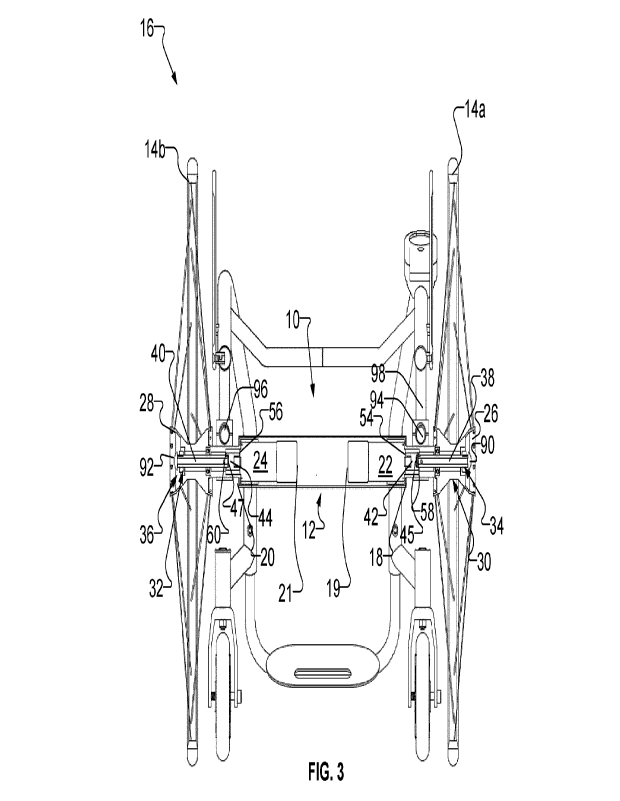
[0012] Figure 3 is a front elevational sectional view of the
propulsion system of Figure 1
installed between a pair of drive wheels of a wheelchair.
[0013] Figure 4 is a front elevational view of a wheelchair showing the
propulsion
system of Figure 1 installed thereto.
[0014] Figure 5 is an exploded view of the drive axle, the
rotatable torque transfer hub,
and the torque receiving member of the propulsion system of Figure 1.
[0015] Figure 6 is an exploded sectional view of the drive axle
and the rotatable torque
transfer hub of the propulsion system of Figure 1, showing the torque
receiving member
integrally formed within the torque transfer hub.
[0016] Figure 7 is a schematic view of the propulsion system of Figure 1.
[0017] Figure 8 is a perspective view of an example axle housing
and mounting bracket
of the propulsion system of Figure 1.
[0018] Figure 9 is a front elevational sectional view of an example
disconnect device of
the propulsion system of Figure 1, showing the drive axle engaged with the
coupler.
[0019] Figure 10 is a front elevational sectional view of the
disconnect device of Figure
9, showing the drive axle disengaged from the coupler.
[0020] Figure 11 is an exploded perspective view of a motor,
axle housing and drive
axle according to another example embodiment.
3
CA 03222461 2023- 12- 12
WO 2023/272380
PCT/CA2022/051027
Detailed Description
[0021] Referring to Figures 1 to 4, in one embodiment the
apparatus of the invention is
a wheelchair propulsion system 10. The propulsion system 10 assists the
propulsion of a
manual wheelchair 16 by providing electric power thereto. The apparatus of
this invention
allows a user to propel the wheelchair 16 manually or electrically, and to
transition between
the two modes seamlessly. The propulsion system 10 may be retrofitted onto a
conventional manual wheelchair 16.
[0022] The propulsion system 10 has an elongated, hollow axle tube 12
dimensioned to
be arranged between a pair of drive wheels 14a, 14b below a seat 18 of the
wheelchair 16.
First and second motors 22, 24 are arranged within the axle tube 12. The first
motor 22
extends from a first end 18 of the axle tube 12 to a first point 19 within the
axle tube 12 to
rotate the first drive wheel 14a. The second motor 24 extends from a second
opposing end
20 of the axle tube 12 to a second point 21 within the axle tube 12 to rotate
the second
drive wheel 14b. The motors 22, 24 may be any suitable electric motors
including for
example brushed or brushless planetary gear motors and direct drive motors.
[0023] Means are provided to control the actuation of the motors
22, 24. As shown
schematically in Figure 7, such means may include a controller 102 connected
to an input
device 100 for receiving signals therefrom, and to the motors 22, 24 for
transmitting signals
thereto, responsive to the input signals received from the input device 100.
The input device
100, controller 102 and motors 22, 24 may be wirelessly connected. A power
source 104,
such as a rechargeable battery, may be connected to supply power to the
controller 102
and the motors 22, 24. The input device 100, controller 102 and power source
104 may be
arranged at any suitable location on the wheelchair 16. For example, the
controller 102 and
power source 104 may be mounted under the seat 18, and the input device 100
may be
mounted on an armrest of the wheelchair 16.
[0024] The input device 100 may for example be a man-machine interface
(MMI) such
as in the form of a joystick, accelerometer, remote control, and/or an mobile
phone
application which can be wired or wirelessly connected to the controller 102
(e.g., by
BluetoothTM or Wi-Fi connectivity), or a brain-machine interface (BMI)
provided in the form
of a computer chip implanted in the brain of the user for sending commands to
the controller
102.
4
CA 03222461 2023- 12- 12
WO 2023/272380
PCT/CA2022/051027
[0025] First and second rotatable torque transfer hubs 26, 28
are mounted within a
centerbore 30, 32 of each of the drive wheels 14a, 14b. The first and second
torque transfer
hubs 26, 28 each have a central bore 34, 36 for receiving a respective first
and second
drive axles 38, 40 therethrough. The first and second drive axles 38, 40 are
insertable
through the central bores 34, 36 for engagement with a respective first and
second couplers
42, 44 at first ends 45, 47 of the drive axles 38, 40. First and second
couplers 42, 44
engage with the respective first and second motors 22, 24 at one end 54, 56,
and the
respective first ends 45, 47 of the first and second drive axles 38, 40 at
their opposite ends
58, 60, thereby connecting the axle tube 12 to the first and second torque
transfer hubs 26,
28.
[0026] First and second axle housings 46, 48 may be arranged to
connect the axle tube
12 at their first ends 49, 51, and to the torque transfer hubs 26, 28 at their
second, opposite
ends 53, 57. The first and second axle housings 46, 48 provide a space for
receiving at
least the respective first and second couplers 42, 44 and a length of the
first and second
drive axles 38, 40. The first and second drive axles 38, 40 extend through the
central bores
34, 36 of the torque transfer hubs 26, 28 into the first and second axle
housings 46, 48 for
engagement with the first and second couplers 42, 44 so as to secure the first
and second
drive axles 38, 40 in a lock position. The locking of the first and second
drive axles 38, 40
ensures proper alignment of the couplers 42, 44 to the respective motors 22,
24, allowing
the axles 38, 40 to rotate.
[0027] Mechanical bearings 50, 52 and/or torque receiving
members 62, 64 may be
provided to facilitate the rotation of the drive axles 38, 40 and thereby the
first and second
torque transfer hubs 26, 28. The mechanical bearings 50, 52 may be arranged
within the
first and second axle housings 46, 48 and/or within the central bores 34, 36
of the torque
transfer hubs 26, 28 dimensioned to surround a length of the drive axles 38,
40.
[0028] As shown in Figure 5, in some embodiments, the torque
receiving members 62,
64 each comprises a torque bushing 63, 65, which may be mounted to an outer
end 82, 84
of the central bores 34, 36 of the first and second torque transfer hubs 26,
28 for
engagement with a respective torque transfer member 86, 88 on the drive axles
38, 40,
facilitating the transfer of a torque from the rotation of the drive axles 38,
40 to the torque
transfer hubs 26, 28. Figure 5 is an exploded view illustrating a drive axle
38, 40 and a
torque transfer hub 26, 28 in combination with a torque bushing 63, 65
according to an
5
CA 03222461 2023- 12- 12
WO 2023/272380
PCT/CA2022/051027
example embodiment. Referring to Figure 5, each of the drive axles 38, 40
includes a nut
66, 68 as the torque transfer member 86, 88. The nut 66, 68 is arranged to
surround a
length of the drive axle 38, 40 adjacent to a respective second end 70, 72 of
the drive axle
38, 40. Each of the nuts 66, 68 has one or more flat faces 74 arranged on its
outer
periphery 75 shaped to be received within a slot 73a, 73b of the torque
bushings 63, 65.
Each of the torque bushings 63, 65 is defined by an inner periphery 78 having
one or more
flat faces 80, shaped to complement the one or more flat faces 74 on the outer
periphery 75
of the nut 66, 68.
[0029] In some embodiments, the torque receiving members 62, 64
may be integrally
arranged at the outer ends 82, 84 of the central bores 34, 36 of each of the
torque transfer
hubs 26, 28, as shown in Figure 6. In such embodiments, one or more flat faces
shaped to
receive the torque transfer members 86, 88 on the drive axles 38, 40 may be
contoured at
the outer ends 82, 84 of the central bores 34, 36 of the torque transfer hubs
26, 28, thereby
omitting the need for torque bushings 63, 65.
[0030] The torque transfer member 86, 88 may be arranged at any point along
the
length of the drive axles 38, 40. In some embodiments, the torque transfer
members 86, 88
may be integrally formed on the surfaces of the drive axles 38, 40. For
example, a length of
the drive axles 38, 40 may be contoured with one or more flat faces for
engagement with
the torque receiving members 62, 64. This embodiment omits the need for the
nut 66, 68.
[0031] First and second mounting brackets 94, 96 may be arranged
to secure the
wheelchair propulsion system 10 to a frame 98 of the wheelchair 16. First and
second
mounting brackets 94, 96 may be mounted at any suitable locations on the
wheelchair
propulsion system 10, such as the first and second axle housings 46, 48. The
mounting
brackets 94, 96 may be secured to any suitable positions along the frame 98 of
the
wheelchair 16.
[0032] Referring to Figure 8, the first and second mounting
brackets 94, 96 each have
an opening 97A, 97B for receiving the first and second axle housings 46, 48
respectively. In
some embodiments, the cross-sectional shapes of the outer peripheries 99A, 99B
of the
first and second axle housings 46, 48 are circular. In such embodiments, the
cross-
sectional shapes of the openings 97A, 97B of the first and second mounting
brackets 94,
96 are circular, with the openings 97A, 97B having smooth inner surfaces 1014,
101B. In
other embodiments, the outer peripheries 99A, 99B of the first and second axle
housings
6
CA 03222461 2023- 12- 12
WO 2023/272380
PCT/CA2022/051027
46, 48 are defined by one or more flat surfaces 105A, 105B being contoured
thereon. In
such embodiments, the inner surfaces 101A, 101B of the openings 97A, 97B of
the first
and second mounting brackets 94, 96 are defined by one or more flat surfaces
107A, 107B
being contoured thereon, the flat surfaces 107A, 107B complementing the one or
more flat
surfaces 105A, 105B defined on the axle housings 46, 48. In one example, eight
flat
surfaces 101A, 101B, 105A, 105B are contoured on the axle housings 46, 48 and
within
the openings 97A, 97B of the mounting brackets 94, 96, such that the cross-
sectional
shape of the axle housings 46, 48 and openings 97A, 97B is an octagon. The
contour
profiles of the axle housings 46, 48 and the openings 97A, 97B of the mounting
brackets
94, 96 assist in retaining the torque applied to the drive axles 38, 40.
[0033] The drive axles 38, 40 may comprise a releasable
mechanism. For example, the
drive axles 38, 40 may each comprise a push button 90, 92 at their second ends
70, 72.
The activation of the push buttons 90, 92 releases the drive axles 38, 40 out
of engagement
from the first and second couplers 42, 44, allowing the torque transfer hubs
26, 28 to
disengage from the axle tube 12 and the axle housings 46, 48, allowing the
drive wheels
14a, 14b to be removed from the wheelchair 16 without using any tools.
[0034] In some embodiments, means are provided to move the
couplers 42, 44 in a
longitudinal direction of the axles tube 12 between an extended position in
which the
couplers 42, 44 engage the respective drive axles 38, 40 so as to rotatably
drive the torque
transfer hubs 26, 28, and a retracted position in which the couplers 42, 44
disengage from
the respective drive axles 38, 40 to disconnect the source of rotational power
to the torque
transfer hubs 26, 28. Such means may include any suitable disconnect devices,
such as an
electromechanical disconnect device. Figures 9 and 10 show an example solenoid
operated
mechanism as the disconnect device. As shown in the Figures 9 and 10 example
embodiments, a solenoid operated mechanism 103 includes a solenoid body 106
arranged
to surround the coupler 42, 44, a solenoid winding 110 arranged to surround
the solenoid
body 106, and a wave spring 108 arranged to be in contact with the coupler 42,
44. To
move the coupler 42, 44 into the extended position to engage with the
respective drive
axles 38, 40, the coupler 42, 44 is energized with a magnetic field, moving
the spring 108
into a compressed position towards the drive axles 38, 40 (see Figure 9). To
move the
coupler 42, 44 to the retracted position, the coupler 42, 44 is not energized,
and thus the
wave spring 108 returns to its normal unstressed position, releasing the drive
axle 38, 40
from engagement with the couplers 42,44 (see Figure 10).
7
CA 03222461 2023- 12- 12
WO 2023/272380
PCT/CA2022/051027
[0035] The propulsion system 10 operates according to the
following method. The
motors 22,24 are actuated, under the control of the controller 102 which
receives from the
input device 100 an input from the user. The actuation of the motors 22, 24
drive a rotation
thereof, transferring a torque to the respective drive axles 38, 40. The drive
axles 38, 40
transfer a torque to the respective torque transfer hubs 26, 28 so as to
rotate the respective
drive wheels 14a, 14b. The drive wheels 14a, 14b may also be manually
propelled by a
user by controlling the movement of the drive wheels 14a, 14b.
[0036] Additional features may be incorporated with the propulsion system
10 to
enhance the functionality of the wheelchair 16. These features include for
example a
braking system such as a regenerative braking system, accelerometer, cruise
control,
autopilot capability, Global Positioning System (GPS), wireless battery
charging,
regenerative battery charging, Universal Serial Bus (USB) ports, voice
activation and
speakers.
[0037] The wheelchair propulsion system 10 may be mechanically
simplified to reduce
the number of component parts. This can be done in many different ways. The
following are
non-limiting examples of some of those ways.
[0038] In some embodiments, the axle tube 12 and the first and
second axle housings
46, 48 are integrally formed to form a housing. In example embodiments, the
housing is
formed of two cross-sectional portions comprising a first housing section and
a second
housing section. The first housing section may comprise a first cross-
sectional portion of
each of the axle tube 12 and the first and second axle housings 46, 48, and
the second
housing section may comprise a second cross-sectional portion of each of the
axle tube 12
and the first and second axle housings 46, 48. The first and second cross-
section portions
may have the same shape and/or size, or different. The first and second cross-
section
portions may be joined together to form the housing after the first and second
motors 22,
24, and first and second couplings 42, 44 and/or mechanical bearings 50, 52
(if present) are
placed therein.
[0039] In some embodiments, separate components for the first
and second couplings
42, 44 are not required. The first and second couplings 42, 44 may be
integrally formed on
the first and second motors 22, 24 respectively. Figure 11 illustrates an
example
8
CA 03222461 2023- 12- 12
WO 2023/272380
PCT/CA2022/051027
embodiment. In example embodiments, the first and second motors 22, 24 each
comprises
a torque transfer profile 150, 152 arranged on a surface 153A, 153B at one end
154, 156
thereof. The torque transfer profiles 150, 152 may each comprise one or more
surfaces,
shaped to engage with the first and second drive axles 38, 40. In some
embodiments, the
torque transfer profiles 150, 152 are each shaped to engage with the
respective first ends
45, 47 of the first and second drive axles 38, 40.
[0040] In some embodiments, the first and second motors 22, 24
are connected to the
respective first and second axle housings 46, 48 with fasteners means such as
screws. In
other embodiments, the first and second motors 22, 24 are connectable to the
respective
first and second axle housings 46, 48 without fastener means. In example
embodiments, as
illustrated in Figure 11, the first and second motors 22, 24 each comprises a
locking profile
158, 160 arranged at the one end 154, 156 thereof. An inner surface 162, 164
of the
respective first and second axle housings 46, 48 may be contoured, shaped and
sized to
engage with the respective locking profile 158, 160, thereby interlocking the
first and
second motors 22, 24 within the first and second axle housings 46, 48
respectively. In some
embodiments, a retaining ring 166, 168 is arranged between the respective
first and second
motors 22, 24 and the respective first and second axle housings 46, 48. The
retaining ring
166, 168 may be dimensioned to surround at least a portion of the respective
motor 22, 24.
In some embodiments, the inner surface 162, 164 of the first and second axle
housings 46,
48 comprise a respective first and second groove 170, 172, sized to receive
the respective
retaining ring 166, 168. This secures the first and second motors 22, 24 in
position within
the first and second axle housings 46, 48, advantageously preventing
rotational torque and
lateral movement of the motors 22, 24 during use.
[0041] Throughout the foregoing description and the drawings, in
which corresponding
and like parts are identified by the same reference characters, specific
details have been
set forth in order to provide a more thorough understanding to persons skilled
in the art.
However, well known elements may not have been shown or described in detail or
at all to
avoid unnecessarily obscuring the disclosure.
[0042] As will be apparent to those skilled in the art in the
light of the foregoing
disclosure, many alterations and modifications are possible in the practice of
this invention
without departing from the scope thereof. Accordingly, the description and
drawings are to
be regarded in an illustrative, rather than a restrictive, sense.
9
CA 03222461 2023- 12- 12