Note: Descriptions are shown in the official language in which they were submitted.
WO 2022/272159
PCT/US2022/035052
PROCESS AND SYSTEM FOR REORIENTING FIBERS IN A
FOAM FORMING PROCESS
RELATED APPLICATIONS
[0001] The present application is based upon and claims
priority to U.S. Provisional Patent
Application Serial No. 63/215,128, having a filing date of June 25, 2021, and
U.S. Provisional Patent
Application Serial No. 63/215,494, having a filing date of June 27, 2021,
which are incorporated herein
by reference.
BACKGROUND
Many tissue products, such as facial tissue, bath tissue, paper towels,
industrial wipers, and
the like, are produced according to a wet laid process. Wet laid webs are made
by depositing an
aqueous suspension of pulp fibers onto a forming fabric and then removing
water from the newly-
formed web.
In order to improve various characteristics of tissue webs, webs have also
been formed
according to a foam forming process. During a foam forming process, a foamed
suspension of fibers
is created and spread onto a moving porous conveyor for producing an embryonic
web. Foam formed
webs can demonstrate improvements in bulk, stretch, caliper, and/or
absorbency.
In addition to tissue webs, foam forming can be used to make all different
types of webs and
products. For example, relatively long fibers and synthetic fibers can be
incorporated into webs using
a foam forming process. Thus, foam forming processes can be more versatile
than many wet laid
processes.
When forming webs according to a foam forming process, however, problems have
been
experienced in controlling the fiber orientation in the resulting web. During
production of the web, for
instance, the foam suspends the fibers and conveys the fibers downstream at a
flow rate that
demonstrates plug flow characteristics and/or a low yield stress.
Consequently, many foam forming
processes produce webs in which the fibers are primarily oriented in the
machine direction of the
webmaking process, especially when the foam formed webs are formed on an
inclined surface.
Thus, a need currently exists for a system and process of producing foam
formed webs in
which there is control over the fiber orientation. In particular, a need
exists for a process and system
that can produce foam formed webs where the fiber orientation is more random
and results in fibers
being oriented in the machine direction and in the cross-machine direction.
Producing webs with a
more uniform fiber orientation distribution can provide various benefits and
advantages. For instance,
the webs can demonstrate a greater uniformity of physical properties between
the machine direction of
the web and the cross-machine direction of the web.
1
CA 03222681 2023- 12- 13
WO 2022/272159
PCT/US2022/035052
SUMMARY
In general, the present disclosure is directed to an improved process and
system for forming
webs from a foamed suspension of fibers. More particularly, the process and
system of the present
disclosure has been particularly designed in order to better control fiber
orientation in webs made from
the process. For example, webs made from the process can demonstrate a more
random fiber
orientation such that a greater amount of fibers are oriented in the machine
direction. In one aspect,
the amount of fibers oriented in the machine direction are proportional to or
substantially equal to the
amount of fibers oriented in the cross-machine direction.
Through the process of the present disclosure, webs can be produced with
improved
properties and characteristics. For example, the webs can display enhanced
stretch characteristics in
both the machine direction and the cross-machine direction. In addition, foam
formed webs made
according to the present disclosure can have a machine direction to cross-
machine direction tensile
strength ratio of from about 0.8 to about 1.8, such as from about 0.9 to about
1.6, such as from about
0.9 to about 1.4, such as from about 0.9 to about 1.2. In one particular
embodiment, the web can have
a machine direction to cross-machine direction tensile strength ratio of from
about 1 to about 1.15.
Webs can be made with high bulk characteristics or low bulk characteristics.
The webs, for
example, can have a bulk of greater than about 3 cc/g, such as greater than
about 5 cc/g, such as
greater than about 7 cc/g, such as greater than about 9 cc/g, such as greater
than about 11 cc/g, such
as greater than 14 cc/g and generally less than about 20 cc/g. Alternatively,
the webs can have a bulk
of less than about 3 cc/g, such as less than about 1 cc/g, such as less than
about 0.5 cc/g, such as
less than about 0.08 cc/g, and generally greater than about 0.03 cc/g.
Webs made according to the present disclosure can have all different types of
basis weights.
For instance, the basis weight can be from about 6 gsm to about 800 gsm, such
as from about 10 gsm
to about 200 gsm, such as from about 20 gsm to about 120 gsm. The webs can be
made exclusively
from pulp fibers or can be made from pulp fibers blended with other fibers,
such as synthetic fibers
and/or superabsorbent particles or fibers. Alternatively, the webs can be made
exclusively from
synthetic polymer fibers, from regenerated cellulose fibers, or from mixtures
thereof. In one aspect,
the synthetic fibers, for instance, can be present in the nonwoven web in an
amount greater than about
5% by weight, such as in an amount greater than about 15% by weight, such as
greater than about
20% by weight, such as in an amount greater than about 25% by weight, and in
an amount up to 100%
by weight. The synthetic fibers can comprise polymer fibers, such as polyester
fibers. Alternatively,
2
CA 03222681 2023- 12- 13
WO 2022/272159
PCT/US2022/035052
the synthetic fibers can comprise regenerated cellulose fibers, such as rayon
fibers, viscose fibers, and
the like.
In order to produce webs as described above, in one embodiment, the process
includes
depositing a foamed suspension of fibers into a mixing chamber. In one aspect,
the foamed
suspension of fibers can be injected into the mixing chamber in at least one
direction and possibly in
two different directions. For example, the foamed suspension of fibers can be
injected into the mixing
chamber in a vertical direction and in a horizontal direction. In one
embodiment, the foamed
suspension of fibers is injected into the mixing chamber from a top of the
mixing chamber and from a
side of the mixing chamber. The foamed suspension can enter the mixing chamber
at a velocity of
greater than about 1 m/sec, such as greater than about 1.5 m/sec, such as
greater than about 2
m/sec, such as greater than about 2.5 m/sec, and less than about 6 m/sec, such
as less than about 5
m/sec, such as less than about 4 m/sec.
The process further includes the step of flowing the foamed suspension of
fibers from the
mixing chamber through a narrow constriction and into a forming zone. For
example, the mixing
chamber can be enclosed except for the narrow constriction. The narrow
constriction can comprise a
slot that extends along the width of the mixing chamber at the bottom. The
slot can cause the foamed
suspension of fibers to reach super-critical flow. The foamed suspension of
fibers moves through the
narrow constriction at a fluid flow rate such that the foamed suspension of
fibers undergoes turbulent
flow within the forming zone. For example, the foamed suspension of fibers can
undergo a hydraulic
jump that forms eddies in the foam and causes better fiber mixing.
The foamed suspension of fibers is conveyed through the forming zone on a
moving forming
surface. The foamed suspension of fibers is drained of fluids through the
forming surface within the
forming zone to form an embryonic web. In one aspect, the velocity of the
moving forming surface is
controlled in relation to the velocity of the foamed suspension of fibers
moving in the machine
direction. For example, a ratio of the foamed suspension of fibers velocity to
the forming surface
velocity during draining of the foamed suspension of fibers in the forming
zone can be from about 1:0.5
to about 1:2, such as from about 1:0.8 to about 1:1.8.
In addition to controlling the velocity of the moving forming surface in
relation to the velocity of
the foamed suspension of fibers, drainage of the foamed suspension of fibers
can be also controlled in
order to preserve fiber orientation that occurs due to the mixing of the
fibers. For example, the forming
zone can have a length and wherein the foamed suspension of fibers can have a
drainage profile over
the length of the forming zone. In one aspect, greater than about 50%, such as
greater than about
60%, such as greater than about 70% of drainage of the foamed suspension of
fibers occurs over an
3
CA 03222681 2023- 12- 13
WO 2022/272159
PCT/US2022/035052
initial 33% of the length of the forming zone. In one aspect, the forming
surface can be inclined in
relation to a horizontal.
The foamed suspension of fibers can be formed according to the present
disclosure by
combining a foam with a fiber furnish. The foam can have a density of from
about 200 g/L to about
600 g/L, such as from about 250 g/L to about 400 g/L. The foamed suspension
can be formed by
combining a foaming agent with water. The foamed fiber suspension in the
mixing chamber can
contain from about 40% to about 65% by volume air.
The present disclosure is also directed to a system for producing nonwoven
webs. The
system includes an enclosed mixing chamber for receiving a foamed suspension
of fibers. The
enclosed mixing chamber includes a top, a bottom, and at least one side wall.
The mixing chamber
has a height and a width. The mixing chamber further comprises a front slice
wall that terminates a
distance from the bottom of the mixing chamber forming a narrow constriction.
Once a foamed
suspension of fibers is deposited into the mixing chamber and mixed, the
foamed suspension of fibers
is directed out of the mixing chamber through the narrow constriction.
The system further includes a moving forming surface in operative association
with the mixing
chamber. The forming surface moves in a machine direction and receives the
foamed suspension of
fibers from the mixing chamber for conveying the foamed suspension of fibers
downstream. Adjacent
to the narrow constriction of the mixing chamber is positioned a forming zone.
The forming zone has a
length that is defined by the moving forming surface. The forming zone further
includes a top forming
surface positioned from the moving forming surface. In one embodiment, the
forming zone has a
gradually decreasing height in the machine direction over the length of the
forming zone. A foamed
suspension of fibers conveyed through the narrow constriction of the mixing
chamber undergoes a
hydraulic jump that can cause turbulent flow of the foamed suspension and
better mixing of the fibers.
The system further includes a drying device positioned downstream from the
forming zone for drying a
web formed in the forming zone. The drying device, for instance, can be a
through-air dryer or one or
more heated drying drums.
Other features and aspects of the present disclosure are discussed in greater
detail below.
BRIEF DESCRIPTION OF THE DRAWINGS
A full and enabling disclosure of the present disclosure is set forth more
particularly in the
remainder of the specification, including reference to the accompanying
figures, in which:
Figure 1 is a schematic diagram of one embodiment of a process in accordance
with the
present disclosure for forming webs from a foamed suspension of fibers;
4
CA 03222681 2023- 12- 13
WO 2022/272159
PCT/US2022/035052
Figure 2 is a cross-sectional view of a system and process for depositing a
foamed
suspension of fibers onto a forming surface in accordance with the present
disclosure;
Figure 3 is a cross-sectional view of a mixing chamber for receiving a foamed
suspension of
fibers in accordance with the present disclosure;
Figure 4 is a diagram illustrating flow of a foamed suspension of fibers when
using the process
and system as shown in Figure 2; and
Figure 5 is a graphical representation of some of the results discussed in the
example below.
Repeat use of reference characters in the present specification and drawings
is intended to
represent the same or analogous features or elements of the present invention.
DEFINITIONS
The term "machine direction" as used herein refers to the direction of travel
of the forming
surface onto which fibers are deposited during formation of a nonwoven web.
The term "cross-machine direction" as used herein refers to the direction
which is
perpendicular to the machine direction defined above.
The term "pulp" as used herein refers to fibers from natural sources such as
woody and non-
woody plants. Woody plants include, for example, deciduous and coniferous
trees. Non-woody plants
include, for example, cotton, flax, esparto grass, milkweed, straw, jute,
hemp, and bagasse. Pulp fibers
can include hardwood fibers, softwood fibers, and mixtures thereof.
The term "average fiber length" as used herein refers to an average length of
fibers, fiber
bundles and/or fiber-like materials determined by measurement utilizing
microscopic techniques. A
sample of at least 20 randomly selected fibers is separated from a liquid
suspension of fibers. The
fibers are set up on a microscope slide prepared to suspend the fibers in
water. A tinting dye is added
to the suspended fibers to color cellulose-containing fibers so they may be
distinguished or separated
from synthetic fibers. The slide is placed under a Fisher Stereomaster II
Microscope--S19642/S19643
Series. Measurements of 20 fibers in the sample are made at 20X linear
magnification utilizing a 0-20
mils scale and an average length, minimum and maximum length, and a deviation
or coefficient of
variation are calculated. In some cases, the average fiber length will be
calculated as a weighted
average length of fibers (e.g., fibers, fiber bundles, fiber-like materials)
determined by equipment such
as, for example, a Kajaani fiber analyzer Model No. FS-200, available from
Kajaani Oy Electronics,
Kajaani, Finland. According to a standard test procedure, a sample is treated
with a macerating liquid
to ensure that no fiber bundles or shives are present. Each sample is
disintegrated into hot water and
diluted to an approximately 0.001% suspension. Individual test samples are
drawn in approximately 50
to 100 ml portions from the dilute suspension when tested using the standard
Kajaani fiber analysis
5
CA 03222681 2023- 12- 13
WO 2022/272159
PCT/US2022/035052
test procedure. The weighted average fiber length may be an arithmetic
average, a length weighted
average or a weight weighted average and may be expressed by the following
equation:
(Xi * ni) n
x= =0
where
k=maximum fiber length
xi-fiber length
ni=number of fibers having length xi
n=total number of fibers measured.
One characteristic of the average fiber length data measured by the Kajaani
fiber analyzer is
that it does not discriminate between different types of fibers. Thus, the
average length represents an
average based on lengths of all different types, if any, of fibers in the
sample.
As used herein the term "staple fibers" means discontinuous fibers made from
synthetic
polymers such as polypropylene, polyester, post consumer recycle (PCR) fibers,
polyester, nylon,
regenerated cellulose fibers (e.g., rayon, viscose, lyocell, modal, etc.) and
the like, and those not
hydrophilic may be treated to be hydrophilic. Staple fibers may be cut fibers
or the like. Staple fibers
can have cross-sections that are round, bicomponent, nnulticomponent, shaped,
hollow, or the like.
As used herein, dry strength or dry tensile strength is measured using a
tensile test. The test
is performed against samples that have been conditioned at 23 C + 1 C and 50%
+ 2% relative
humidity for a minimum of 4 hours. The samples are cut into three-inch by six-
inch samples using a
precision sample cutter model JDC 15M-10, available from Thwing-Albert
Instruments, located in
Philadelphia, PA.
The gauge length of the tensile frame is set to 4 inches. The tensile frame is
an Alliance RI/1
frame run with TestWorks 4 software. The tensile frame and the software are
available from MTS
Systems Corporation, located in Minneapolis, MN.
A sample is placed in the jaws of the tensile frame and subjected to a strain
applied at a rate
of 25.4 cm per minute until the point of sample failure. The stress on the
sample is monitored as a
function of the strain. The calculated outputs include the peak load (grams-
force/3 inches, measured
in grams-force), the peak stretch (%, calculated by dividing the elongation of
the sample by the original
length of the sample and multiplying by 100%), the percent stretch at 500
grams-force, the tensile
energy absorption (TEA) at break (grams-forcecm/cm2, calculated by integrating
or taking the area
6
CA 03222681 2023- 12- 13
WO 2022/272159
PCT/US2022/035052
under the stress-strain curve up to the point of failure where the load falls
to 30% of its peak value),
and the slope A (kilograms-force, measured as the slope of the stress-strain
curve from 57-150 grams-
force).
A product is measured using five replicate samples. The product is tested in
the machine
direction and the cross-machine direction.
Wet strength or wet tensile strength is measured in the same manner as dry
strength except
that the samples are wetted prior to testing. Specifically, in order to wet a
sample, a 3 inch x 5 inch
tray is filled with distilled or deionized water at a temperature of 23 C + 2
C. The water is added to the
tray to an approximate 1 cm depth.
A 3M "Scotch-Brite" general purpose scrubbing pad is cut to dimensions of 2.5
inches by 4
inches. A piece of masking tape approximately 5 inches long is placed along
one of the four inch
edges of the pad. The masking tape is used to hold the scrubbing pad.
The scrubbing pad is then placed in the water with the taped end facing up.
The pad remains
in the water at all times until testing is completed. The sample to be tested
is placed on blotter paper
that conforms to TAPP! T205. The scrubbing pad is removed from the water bath
and tapped lightly
three times on a screen associated with the wetting pan. The scrubbing pad is
then gently placed on
the sample parallel to the width of the sample in the approximate center. The
scrubbing pad is held in
place for approximately one second. The sample is then immediately put into
the tensile tester and
tested.
To calculate the wet/dry tensile strength ratio, the wet tensile strength
value is divided by the
dry tensile strength value.
DETAILED DESCRIPTION
It is to be understood by one of ordinary skill in the art that the present
discussion is a
description of exemplary embodiments only and is not intended as limiting the
broader aspects of the
present disclosure.
In general, the present disclosure is directed to a system and process for
forming webs,
including all different types of nonwoven webs including tissue webs, such as
facial tissues, bath
tissues, paper towels and the like; webs suitable for wiping products,
including industrial wipers, pre-
moistened wipers, and the like; and nonwoven webs for incorporation into
absorbent articles such as
diapers, adult incontinence products, feminine hygiene products, pull-ups,
swim diapers, and the like.
In accordance with the present disclosure, the webs are formed from a foamed
suspension of fibers.
The foamed suspension of fibers is deposited or injected into the web forming
process according to a
particular flow path that has been found to provide control over the
orientation of the fibers that are
7
CA 03222681 2023- 12- 13
WO 2022/272159
PCT/US2022/035052
used to form the web. In particular, the system and process of the present
disclosure can be used to
create webs having a more random fiber orientation that results in more
uniformity in the amount of
fibers that are oriented in the machine direction in comparison to the number
of fibers that are oriented
in the cross-machine direction. More random but uniform fiber orientation as
described above results
in webs having more uniform properties when comparing the physical properties
of the web in the
machine direction versus the physical properties of the web in the cross-
machine direction.
As will be explained in greater detail below, the process and system of the
present disclosure
can also be used to control fiber orientation. For example, webs can be formed
according to the
present disclosure that have greater orientation in the machine direction or
have greater orientation in
the cross-machine direction depending upon the desired result. Consequently,
the system and
process of the present disclosure can also be used to produce webs having
tailored properties for a
particular end use application. For instance, through the process of the
present disclosure, webs can
be formed having improved stretch properties, improved absorbency
characteristics, increased bulk if
desired, increased caliper if desired, and/or increased basis weight.
Additionally, a combination of
different properties can be enhanced and improved.
There are many advantages and benefits to a foam forming process as described
above.
During a foam forming process, water is replaced with foam as the carrier for
the fibers that form the
web. The foam, which represents a large quantity of air, is blended with
papermaking fibers. Since
less water is used to form the web, less energy is required in order to dry
the web.
According to the present disclosure, the foam forming process is combined with
a unique fiber
orientation and/or mixing process for producing webs having a desired balance
of properties. The
fiber orientation and/or mixing process can include first forming a foamed
suspension of fibers and
mixing the foamed suspension of fibers in a mixing chamber. The foamed
suspension of fibers, for
instance, can be injected into the mixing chamber that causes the fibers to
mix and form a
homogenous fiber distribution. The mixing chamber can be enclosed except for a
narrow constriction.
For example, the mixing chamber can include a front slice wall that forms a
slot through which the
foamed suspension of fibers is directed. More particularly, the foamed
suspension of fibers flow
through the narrow constriction at a super-critical flow rate and into an open
and enlarged forming
zone. Moving through the narrow constriction and into the forming zone causes
the foamed
suspension of fibers to increase in velocity or flow rate and then quickly
decrease in velocity or flow
rate that causes turbulent flow to occur and the creation of eddy currents. In
this manner, the narrow
constriction and forming zone cause the foamed suspension of fibers to undergo
a hydraulic jump that
8
CA 03222681 2023- 12- 13
WO 2022/272159
PCT/US2022/035052
further causes uniform and homogeneous mixing of the fibers, creating better
fiber orientation in the
cross-machine direction in comparison to the machine direction.
Once the foamed suspension of fibers undergoes turbulent flow within the
forming zone, the
foamed suspension of fibers is conveyed on a porous forming surface. One or
more vacuum devices
can be positioned below the forming surface for draining fluids from the
aqueous suspension of fibers.
In accordance with the present disclosure, at the point of the hydraulic jump
of the foamed suspension
of fibers, the foamed suspension is drained while the forming surface is
moving at a controlled velocity
in order to preserve the fiber orientation created in the forming zone for
creating an embryonic web
that is further fed downstream for further processing and drying. For example,
during formation of the
embryonic web, the velocity of the forming surface in relation to the velocity
of the foamed suspension
of fibers and the drainage profile of the foamed suspension of fibers are
controlled in order to lock in
the fiber orientation that is created during the hydraulic jump. For example,
in one embodiment, the
velocity of the moving forming surface is substantially matched with the
velocity of the foamed
suspension of fibers in the machine direction. In addition, individual drain
boxes can be used such
that most of the fluids are drained from the foamed suspension of fibers at
the beginning of the forming
surface. For example, the forming surface can have a length and greater than
50%, such as greater
than about 60%, such as greater than about 70% of drainage of the fluids by
volume or weight occur
over the initial 33% of the length of the forming surface.
In forming nonwoven webs, which may include tissue or paper webs or nonwoven
synthetic
fiber webs, in accordance with the present disclosure, in one embodiment, a
foam is first formed by
combining water with a foaming agent. The foaming agent, for instance, may
comprise any suitable
surfactant. In one embodiment, for instance, the foaming agent may comprise
sodium lauryl sulfate,
which is also known as sodium laureth sulfate or sodium lauryl ether sulfate.
Other foaming agents
include sodium dodecyl sulfate or ammonium lauryl sulfate. In other
embodiments, the foaming agent
may comprise any suitable cationic and/or amphoteric surfactant. For instance,
other foaming agents
include fatty acid amines, amides, amine oxides, fatty acid quaternary
compounds, and the like.
In one embodiment, a nonionic surfactant is used. The nonionic surfactant, for
instance, may
comprise an alkyl polyglycoside. In one aspect, for instance, the surfactant
can be a C8 alkyl
polyglycoside, a C10 alkyl polyglycoside, or a mixture of C8 and C10 alkyl
polyglycosides.
The foaming agent is combined with water generally in an amount greater than
about 0.1% by
weight, such as in an amount greater than about 0.5% by weight, such as in an
amount greater than
about 0.7% by weight. One or more foaming agents are generally present in an
amount of from about
0.01% by weight to about 5% by weight, such as in an amount up to about 2% by
weight.
9
CA 03222681 2023- 12- 13
WO 2022/272159
PCT/US2022/035052
Once the foaming agent and water are combined, the mixture is blended or
otherwise
subjected to forces capable of forming a foam. A foam generally refers to a
porous matrix, which is an
aggregate of hollow cells or bubbles which may be interconnected to form
channels or capillaries.
The foam density can vary depending upon the particular application and
various factors
including the fiber furnish used. In one embodiment, for instance, the foam
density of the foam can be
greater than about 200 g/L, such as greater than about 250 g/L, such as
greater than about 300 g/L.
The foam density is generally less than about 600 g/L, such as less than about
500 g/L, such as less
than about 400 g/L, such as less than about 350 g/L. In one embodiment, for
instance, a lower density
foam is used having a foam density of generally less than about 350 g/L, such
as less than about 340
g/L, such as less than about 330 g/L. The foam will generally have an air
content of greater than
about 40%, such as greater than about 50%, such as greater than about 60% (at
STP). The air
content is generally less than about 75% by volume, such as less than about
70% by volume, such as
less than about 65% by volume.
The foam can be formed in the presence of a fiber furnish or, alternatively,
the foam can first
be formed and then combined with a fiber furnish. In general, any fibers
capable of making a
basesheet, such as a tissue web or other type of nonwoven web in accordance
with the present
disclosure may be used.
Fibers suitable for making webs comprise any natural or synthetic cellulosic
fibers including,
but not limited to nonwoody fibers, such as cotton, abaca, kenaf, sabai grass,
flax, esparto grass,
straw, jute hemp, bagasse, milkweed floss fibers, and pineapple leaf fibers;
and woody or pulp fibers
such as those obtained from deciduous and coniferous trees, including softwood
fibers, such as
northern and southern softwood kraft fibers: hardwood fibers, such as
eucalyptus, maple, birch, and
aspen. Pulp fibers can be prepared in high-yield or low-yield forms and can be
pulped in any known
method, including kraft, sulfite, high-yield pulping methods and other known
pulping methods. Fibers
prepared from organosolv pulping methods can also be used.
A portion of the fibers, such as up to 100% or less by dry weight can be
synthetic fibers. For
example synthetic fibers can be present in the web in an amount greater than
about 5% by weight,
such as in an amount greater than 10% by weight, such as in an amount greater
than 20% by weight,
such as in an amount greater than 30% by weight, such as in an amount greater
than 40% by weight,
such as in an amount greater than 50% by weight, such as in an amount greater
than 60% by weight,
such as in an amount greater than 70% by weight, such as in an amount greater
than 80% by weight,
such as in an amount greater than 85% by weight, and in an amount less than
about 100% by weight,
such as in an amount less than about 90% by weight, such as in an amount less
than about 80% by
CA 03222681 2023- 12- 13
WO 2022/272159
PCT/US2022/035052
weight, such as in an amount less than about 70% by weight, such as in an
amount less than about
60% by weight, such as in an amount less than about 50% by weight, such as in
an amount less than
about 40% by weight, such as in an amount less than about 30% by weight. In
one aspect, synthetic
fibers are present in the nonwoven web in an amount of from about 5% to about
70% by weight
including all increments of 1% by weight therebetween, such as from 5% to
about 30% by weight.
Synthetic fibers include rayon fibers, polyolefin fibers, polyester fibers,
bicomponent sheath-core
fibers, multi-component binder fibers, and the like. The fibers can be virgin
fibers or recycled fibers.
The fibers can be staple fibers and can have an average length of from about 3
mm to about 150 mm.
An exemplary polyethylene fiber is FybrelO, available from Minifibers, Inc.
(Jackson City, Tenn.),
When containing synthetic polymer fibers, the web can be thermally bonded
where the fibers intersect.
In one aspect, the nonwoven web can contain pulp fibers, such as softwood
fibers, combined
with polyester fibers. The polyester fibers can be staple fibers having a size
of from about 0.5 denier
to about 2.5 denier. The polyester fibers can be contained in the web in an
amount of from about 5%
by weight to about 50% by weight, such as from 10% by weight to about 40% by
weight.
Synthetic cellulose fiber types include regenerated cellulose fibers, such as
rayon in all its
varieties and other fibers derived from viscose or chemically-modified
cellulose. Chemically treated
natural cellulosic fibers can be used such as mercerized pulps, chemically
stiffened or crosslinked
fibers, or sulfonated fibers. For good mechanical properties in using
papermaking fibers, it can be
desirable that the fibers be relatively undamaged and largely unrefined or
only lightly refined. While
recycled fibers can be used, virgin fibers are generally useful for their
mechanical properties and lack
of contaminants. Mercerized fibers, regenerated cellulosic fibers, cellulose
produced by microbes,
rayon, and other cellulosic material or cellulosic derivatives can be used.
Suitable papermaking fibers
can also include recycled fibers, virgin fibers, or mixes thereof. In certain
embodiments capable of high
bulk and good compressive properties, the fibers can have a Canadian Standard
Freeness of at least
200, more specifically at least 300, more specifically still at least 400, and
most specifically at least
500.
Other papermaking fibers that can be used in the present disclosure include
paper broke or
recycled fibers and high yield fibers. High yield pulp fibers are those
papermaking fibers produced by
pulping processes providing a yield of about 65% or greater, more specifically
about 75% or greater,
and still more specifically about 75% to about 95%. Yield is the resulting
amount of processed fibers
expressed as a percentage of the initial wood mass. Such pulping processes
include bleached
chemithermomechanical pulp (BCTMP), chemithermomechanical pulp (CTMP),
pressure/pressure
thermomechanical pulp (PIMP), thermomechanical pulp (IMP), thermomechanical
chemical pulp
11
CA 03222681 2023- 12- 13
WO 2022/272159
PCT/US2022/035052
(TMCP), high yield sulfite pulps, and high yield Kraft pulps, all of which
leave the resulting fibers with
high levels of lignin. High yield fibers are well known for their stiffness in
both dry and wet states
relative to typical chemically pulped fibers.
The web can also be formed without a substantial amount of inner fiber-to-
fiber bond strength.
In this regard, the fiber furnish used to form the base web can be treated
with a chemical debonding
agent, especially when cellulose fibers are present. The debonding agent can
be added to the foamed
fiber slurry during the pulping process or can be added directly to the
headbox. Suitable debonding
agents that may be used in the present disclosure include cationic debonding
agents such as fatty
dialkyl quaternary amine salts, mono fatty alkyl tertiary amine salts, primary
amine salts, imidazoline
quaternary salts, silicone quaternary salt and unsaturated fatty alkyl amine
salts. Other suitable
debonding agents are disclosed in U.S. Pat. No. 5,529,665 to Kaun which is
incorporated herein by
reference. In particular, Kaun discloses the use of cationic silicone
compositions as debonding agents.
In one embodiment, the debonding agent used in the process of the present
disclosure is an
organic quaternary ammonium chloride and, particularly, a silicone-based amine
salt of a quaternary
ammonium chloride. For example, the debonding agent can be PROSOFT®
TQ1003, marketed
by the Hercules Corporation. The debonding agent can be added to the fiber
slurry in an amount of
from about 1 kg per metric tonne to about 10 kg per metric tonne of fibers
present within the slurry.
In an alternative embodiment, the debonding agent can be an imidazoline-based
agent. The
imidazoline-based debonding agent can be obtained, for instance, from the
Witco Corporation. The
imidazoline-based debonding agent can be added in an amount of between 2.0 to
about 15 kg per
metric tonne.
Other optional chemical additives may also be added to the aqueous papermaking
furnish or
to the formed embryonic web to impart additional benefits to the product and
process. The following
materials are included as examples of additional chemicals that may be applied
to the web. The
chemicals are included as examples and are not intended to limit the scope of
the invention. Such
chemicals may be added at any point in the papermaking process.
Additional types of chemicals that may be added to the paper web include, but
is not limited
to, absorbency aids usually in the form of cationic, anionic, or non-ionic
surfactants, humectants and
plasticizers such as low molecular weight polyethylene glycols and polyhydroxy
compounds such as
glycerin and propylene glycol. Materials that supply skin health benefits such
as mineral oil, aloe
extract, vitamin E, silicone, lotions in general and the like may also be
incorporated into the finished
products.
12
CA 03222681 2023- 12- 13
WO 2022/272159
PCT/US2022/035052
In general, the products of the present disclosure can be used in conjunction
with any known
materials and chemicals that are not antagonistic to its intended use.
Examples of such materials
include but are not limited to odor control agents, such as odor absorbents,
activated carbon fibers
and particles, baby powder, baking soda, chelating agents, zeolites, perfumes
or other odor-masking
agents, cyclodextrin compounds, oxidizers, and the like. Superabsorbent
particles may also be
employed. Additional options include cationic dyes, optical brighteners,
humectants, emollients, and
the like.
In order to form the web, the foam is combined with a selected fiber furnish
in conjunction with
any auxiliary agents. The foamed suspension of fibers can be pumped to a tank
and from the tank is
fed to a headbox. Alternatively, the foamed suspension can be pumped directly
to or formed directly
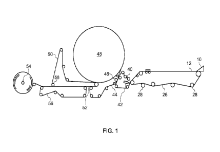
in the headbox without the use of an intervening tank. FIG. 1, for instance,
shows one embodiment of
a process in accordance with the present disclosure for forming a web. As
shown particularly in FIG.
1, from a headbox 10, the foamed fiber suspension is issued from the headbox
onto an endless
traveling fabric 26 supported and driven by rolls 28 in order to support a wet
embryonic web 12. The
web 12 may comprise a single homogeneous layer of fibers or may include a
stratified or layered
construction. The system can include a single headbox or can include a
plurality of headboxes that
work in conjunction to create a nonwoven web.
Once the wet web is supported on the fabric 26, the web is conveyed downstream
and further
dewatered and dried.
In accordance with the present disclosure, the foamed suspension of fibers
undergoes mixing
and turbulent flow in a manner that produces a web with a desired fiber
orientation. In one aspect, for
instance, fiber orientation can be controlled within the headbox 10. The
headbox 10, for instance, is
illustrated in greater detail in FIGS. 2 and 3. Referring to FIG. 2, for
instance, the process of the
present disclosure includes a mixing chamber 14 that is designed to receive
the foamed suspension of
fibers. In the embodiment illustrated in FIGS. 2 and 3, the mixing chamber 14
has a rectangular cross-
sectional shape that extends over the width of the papermaking system. The
mixing chamber 14,
however, can have any suitable shape. For example, in other embodiments, the
mixing chamber 14
may include curved surfaces that better enhance fiber mixing.
As shown in FIG. 3, the mixing chamber 14 includes a top 16 spaced from a
bottom 18. The
mixing chamber 14 further includes side wall 20 and a pair of opposing end
walls that enclose the
ends of the mixing chamber 14 along the width direction. In accordance with
the present disclosure,
the mixing chamber 14 further includes a front slice wall 22. The front slice
wall extends from the top
16 of the mixing chamber 14 and terminates prior to the bottom 18. More
particularly, the front slice
13
CA 03222681 2023- 12- 13
WO 2022/272159
PCT/US2022/035052
wall 22 forms a narrow constriction 24 with the bottom 18 of the mixing
chamber 14. The narrow
constriction 24, in the embodiment illustrated, is in the shape of a slot that
extends over the width of
the mixing chamber 14. As will be described in greater detail below, a foamed
suspension of fibers
deposited or injected into the mixing chamber 14 is directed out of the mixing
chamber 14 through the
narrow constriction 24.
In the embodiment illustrated, the front slice wall 22 forms a narrow
constriction 24 with the
bottom 18 of the mixing chamber 14. It should be understood, however, that the
narrow constriction
24 can be elevated in the mixing chamber 14 and located at any suitable
location on the front slice
wall 22. In addition, the narrow constriction can have any suitable cross-
sectional shape.
The foamed suspension of fibers can be fed to the mixing chamber 14 using
various
techniques and processes. For example, the foamed suspension of fibers can be
injected into the
mixing chamber in a manner that promotes better mixing of the fibers.
In one aspect, the foamed suspension of fibers is injected into the mixing
chamber 14 in at
least two different directions. For example, as shown in FIG. 3, an injector
pump 34 can be used to
inject an aqueous suspension of fibers through one or more top nozzles 28
positioned at the top 16 of
the mixing chamber 14 and through one or more side nozzles 30 positioned along
the side wall 20 of
the mixing chamber 14. In this manner, the foamed suspension of fibers is
injected into the mixing
chamber 14 from a vertical direction and from a horizontal direction. The
vertical stream of fibers and
the horizontal stream of fibers intersect within the mixing chamber 14 and
promote robust mixing
within the chamber.
The foamed suspension can enter the mixing chamber at a velocity of greater
than about 1
m/sec, such as greater than about 1.5 m/sec, such as greater than about 2
m/sec, such as greater
than about 2.5 m/sec, and less than about 6 m/sec, such as less than about 5
m/sec, such as less
than about 4 m/sec. The mixing chamber 14 as shown in FIG. 3 represents one
embodiment of a
method for initially mixing the fibers within the foamed suspension. In other
embodiments, however,
the foamed suspension of fibers may only be injected into the mixing chamber
14 along a single
direction that includes baffles or curved surfaces for promoting mixing. In
still other embodiments, the
foamed suspension of fibers can be injected into the mixing chamber 14 from
greater than two
different directions.
Once injected into the mixing chamber 14 and mixed, the foamed suspension of
fibers is
directed through the narrow constriction 24 formed by the front slice wall 22.
As shown in FIG. 2, after
exiting the narrow constriction 24, the foamed suspension of fibers enters a
forming zone 60 that
permits the foamed suspension of fibers to expand in volume. As shown in FIG.
2, for example, the
14
CA 03222681 2023- 12- 13
WO 2022/272159
PCT/US2022/035052
forming zone 60 extends over the width of the nonwoven web making machine,
such as a
papermaking machine when containing pulp fibers, and is defined as the space
between a moving
forming surface 62 and a top forming surface 64. As shown in FIG. 2, the
moving forming surface can
be positioned at an incline to the horizontal. For example, the forming
surface 62 can be at an angle
of greater than about 5 , such as greater than about 100, such as greater than
about 15 , such as
greater than about 200, such as greater than about 25 , such as greater than
about 30 with respect
to the horizontal. The angle of the forming surface 62 is generally less than
about 600, such as less
than about 500, such as less than about 400, such as less than about 300.
Although optional, the
inclined forming surface can assist in draining the foamed suspension of
fibers and can assist in
forming an embryonic web 12.
As shown in FIG. 2, the forming zone formed between the moving forming surface
62 and the
top forming surface 64 can have a gradually decreasing volume. The gradually
decreasing volume of
the forming zone 60, for instance, can help channel the foamed suspension of
fibers downstream and
facilitate formation of the embryonic web 12. Thus, the forming zone 60
generally has a relatively
large volume adjacent the narrow constriction 24 and then gradually decreases
to a smaller volume at
the opposite end. Having an expansive or larger volume adjacent the narrow
constriction 24 permits
expansion of the foamed suspension of fibers as the foamed suspension enters
the forming chamber
and consequently promotes better mixing of the fibers. For example, the height
of the forming
chamber 60 adjacent the narrow constriction 24 can be the same height as the
mixing chamber 14 or
can have a height that is higher than the mixing chamber 16 as shown in FIG.
2. For example, the
height of the forming chamber 60 adjacent the narrow constriction 24 can be at
least about 1.3 times,
such as at least about 1.5 times, such as at least about 1.8 times, such as at
least about 2 times, such
as at least about 2.3 times, such as at least about 2.5 times, such as at
least about 2.8 times, such as
at least about 3 times, such as at least about 3.5 times, such as at least
about 4 times, such as at
least about 4.5 times the height of the narrow constriction 24 and generally
less than about 5 times the
height of the narrow constriction. The height of the forming chamber 60
adjacent the narrow
constriction 24 is generally not limited but for practical purposes can be
about the same as the height
of the mixing chamber 16.
As described above, the foamed suspension of fibers exits the mixing chamber
14 and is
operatively deposited onto the moving forming surface 62. The moving forming
surface 62 can be a
felt, wire, or screen and is porous for allowing fluids to drain from the
foamed suspension of fibers. In
one embodiment, as shown in FIG. 2, one or more drain boxes can be positioned
below the moving
forming surface 62 for facilitating draining of the foamed suspension. In the
embodiment illustrated in
CA 03222681 2023- 12- 13
WO 2022/272159
PCT/US2022/035052
FIG. 2, for instance, the system includes three drain boxes 66, 68 and 70.
Each drain box 66, 68 and
70 can be associated with a vacuum or suction device for applying a suction
force to a foamed
suspension of fibers being conveyed on the moving forming surface 62. In one
aspect, for instance, a
single vacuum device can be used to apply suction from each of the different
drain boxes 66, 68 and
70. The vacuum device can be placed in operative association with each of the
drain boxes in a
manner such that the amount of suction in each drain box can be varied
individually. Alternatively,
each drain box 66, 68 and 70 can be associated with a separate vacuum device
for controlling the
amount of suction forces within each drain box. Having multiple drain boxes
below the moving forming
surface 62 permits controlled draining of the foamed suspension of fibers. For
example, drainage over
the length of the forming surface 62 can be uniform or can be varied such that
there is a particular
drainage profile as the embryonic web 12 is formed.
Referring now to FIG. 4, one embodiment of a flow profile and drainage profile
of a foamed
suspension of fibers processed according to the present disclosure is shown.
As shown in FIG. 4, a
foamed suspension of fibers 72 is contained in the mixing chamber 14 in a well-
mixed state. From the
mixing chamber 14, the foamed suspension of fibers 72 is forced through the
narrow constriction 24.
The narrow constriction 24 has a size that causes the foamed suspension of
fibers 72 to rapidly
increase in velocity and flow rate. The foamed suspension of fibers 72 then
exits the narrow
constriction 24 and discharges into the forming zone 60. The rapid increase in
flow rate followed by a
significant decrease in flow rate of the foamed suspension of fibers 72 causes
significant turbulence to
occur in the forming chamber 60 causing further mixing of the fibers. Through
this process, the
orientation of the fibers, as opposed to only being oriented in the flow
direction, becomes much more
random. Consequently, fiber orientation in the machine direction can be the
same or similar to the
fiber orientation in the cross-machine direction. As shown in FIG. 4, after
exiting the narrow
constriction 24, the foamed suspension of fibers 72 is then drained through
the forming surface 62 for
preserving and locking in the fiber orientation. In this manner, embryonic
webs 12 can be produced
that have physical properties in the machine direction that are very similar
to physical properties in the
cross-machine direction.
One method for determining whether a web has random fiber orientation as
opposed to fiber
orientation primarily in a single direction is to measure the tensile strength
of the web in both the
machine direction and the cross-machine direction and determine a ratio. A
ratio of 1 indicates that
fiber orientation is generally equal in both directions. Webs made according
to the present disclosure,
for instance, can have a machine direction to cross-machine direction tensile
strength ratio of
generally greater than about 0.8, such as greater than about 0.9, such as
greater than about 1, such
16
CA 03222681 2023- 12- 13
WO 2022/272159
PCT/US2022/035052
as greater than about 1.1. The machine direction to cross-machine direction
tensile strength ratio of
the web can generally be less than about 1.8, such as less than about 1.6,
such as less than about
1.4, such as less than about 1.2. It should be understood, however, that the
process and system of
the present disclosure can also be used to control fiber orientation. Thus,
the process and system can
also be used to produce webs that have fibers oriented primarily in a single
direction. Consequently,
in other embodiments, the process and system of the present disclosure can be
used to produce webs
having a machine direction to cross-machine direction tensile strength ratio
outside of the ranges
described above.
As explained above, in FIG. 4, the foamed suspension of fibers 72 is first
mixed in a mixing
chamber, accelerated in flow rate and velocity through the narrow constriction
24 and then discharged
into a forming zone 60 that has an expansive volume allowing the foamed
suspension of fibers to
rapidly decrease in velocity and flow rate causing turbulent flow within the
fluid and resulting in random
fiber orientation. Turbulent flow refers to flow of the foamed suspension in
which the fluid undergoes
irregular fluctuations, or mixing, in contrast to laminar flow in which the
fluid moves in smooth paths or
layers. In the process illustrated in FIG. 4, for instance, the foamed
suspension of fibers can undergo
turbulent flow within the forming chamber 60 causing fluid swirls and eddies
to be created that
significantly enhance random distribution of the fibers within the foam.
In one embodiment, for instance, the foamed suspension of fibers 72 undergoes
a hydraulic
jump from the mixing chamber 14 to the forming zone 60. A hydraulic jump, for
instance, can occur
when a shallow, high velocity fluid meets slower moving fluid causing a rapid
dissipation of kinetic
energy. For example, when a fluid at high velocity discharges into a zone of
lower velocity, a rather
abrupt rise can occur in the fluid surface. The rapidly flowing fluid is
abruptly slowed and increases in
height which releases kinetic energy resulting in turbulence and/or the
formation of eddies. For
example, under some conditions, the transition of the fluid from fast velocity
to slow velocity causes
the fluid to curl back upon itself which, in the process of the present
disclosure, causes the fibers to
undergo intensive mixing and reorientation.
In one embodiment, flow of the foamed suspension of fibers reaches super-
critical flow within
the narrow constriction 24 followed by sub-critical flow within the forming
chamber 60. Super-critical
flow occurs when flow is dominated by inertial forces as opposed to
gravitational forces and can
behave as rapid or unstable flow. Super-critical flow has a Froude number of
greater than 1. Sub-
critical flow, on the other hand, is dominated by gravitational forces and
behaves in a slower stable
way. As flow transitions from super-critical flow to sub-critical flow, a
hydraulic jump can occur which
represents a high energy loss, turbulent flow, and a random orientation of the
fibers.
17
CA 03222681 2023- 12- 13
WO 2022/272159
PCT/US2022/035052
In one aspect of the present disclosure, the flow of the foamed suspension of
fibers through
the narrow constriction 24 can operate at a desired Froude number. For
instance, the Froude number
of the foamed suspension of fibers can be greater than about 2, such as
greater than about 5, such as
greater than about 10, such as greater than about 15, such as greater than
about 20, such as greater
than about 25, such as greater than about 30, and generally less than about
50, such as less than
about 40.
Once the foamed suspension of fibers 72 has been discharged into the forming
zone 60 and
undergone fiber reorientation, the foamed suspension of fibers is drained from
fluids in an effort to
keep intact and lock in the fiber orientation within the resulting web. Two
factors that can affect fiber
orientation include the relative velocity of the forming surface 62 in
relation to the velocity of the
foamed suspension of fibers in the machine direction and the drainage profile
of the foamed
suspension.
For example, in one aspect, the velocity of the moving forming surface 62 is
controlled so as
to prevent the fibers contained within the foamed suspension from reorienting
into a primarily machine
direction orientation. In this regard, the speed of the moving forming surface
62 can be matched with
the speed at which the foamed suspension of fibers is flowing in the machine
direction through the
forming zone 60. In one aspect, for example, the foamed suspension of fibers
moves at a velocity in a
machine direction in the forming zone and the forming surface moves at a
velocity and wherein a ratio
of the foamed suspension of fibers velocity to the forming surface velocity
during draining of the
foamed suspension of fibers is from about 1:0.5 to about 1:2, such as from
about 1:0.8 to about 1:1.8.
In addition to the velocity of the forming surface 62, the drainage profile of
the foamed
suspension of fibers can also be controlled in order to maintain the desired
fiber orientation. For
example, the forming zone can have a length and wherein the foamed suspension
of fibers has a
drainage profile over the length of the forming zone such that drainage is
substantially the same from
the beginning of the forming zone to an end of the forming zone. For example,
in one embodiment,
the drainage profile does not change by more than about 20%, such as by no
more than about 10%
over the length of the forming zone in terms of either volume of fluid drained
or weight of fluid drained.
Alternatively, as shown in FIG. 4, the system can be designed so that greater
drainage of the
fluids occurs at the beginning of the forming surface and then gradually
decreases towards the end of
the forming surface. For example, as shown in FIG. 2, drain boxes 66, 68 and
70 can be used to
produce any desired drainage profile. In one embodiment, for example, the
drainage profile over the
length of the forming zone is such that greater than about 50%, such as
greater than about 55%, such
18
CA 03222681 2023- 12- 13
WO 2022/272159
PCT/US2022/035052
as greater than about 60%, such as greater than about 65%, such as even
greater than about 70% of
fluid drainage occurs over an initial 33% of the length of the forming zone.
Once the foamed suspension of fibers is formed into a web, the web may be
processed using
various techniques and methods. For example, in FIG. 1, a method is shown for
making throughdried
nonwoven webs and is shown for exemplary purposes only. (For simplicity, the
various tensioning
rolls schematically used to define the several fabric runs are shown, but not
numbered. It will be
appreciated that variations from the apparatus and method illustrated in FIG.
1 can be made without
departing from the general process).
The wet web is transferred from the fabric 26 to a transfer fabric 40. In one
embodiment, the
transfer fabric can be traveling at a slower speed than the forming fabric in
order to impart increased
stretch into the web. This is commonly referred to as a "rush" transfer. The
transfer fabric can have a
void volume that is equal to or less than that of the forming fabric. The
relative speed difference
between the two fabrics can be from 0-60 percent, more specifically from about
15-45 percent.
Transfer can be carried out with the assistance of a vacuum shoe 42 such that
the forming fabric and
the transfer fabric simultaneously converge and diverge at the leading edge of
the vacuum slot.
The web is then transferred from the transfer fabric to the throughdrying
fabric 44 with the aid
of a vacuum transfer roll 46 or a vacuum transfer shoe. The throughdrying
fabric can be traveling at
about the same speed or a different speed relative to the transfer fabric. If
desired, the throughdrying
fabric can be run at a slower speed to further enhance stretch. Transfer can
be carried out with
vacuum assistance to ensure deformation of the sheet to conform to the
throughdrying fabric, thus
yielding desired bulk and appearance if desired. Suitable throughdrying
fabrics are described in U.S.
Pat. No. 5,429,686 issued to Kai F. Chiu et al. and U.S. Pat. No. 5,672,248 to
Wendt, et al. which are
incorporated by reference.
In one embodiment, the throughdrying fabric contains high and long impression
knuckles. For
example, the throughdrying fabric can have about from about 5 to about 300
impression knuckles per
square inch which are raised at least about 0.005 inches above the plane of
the fabric. During drying,
the web can be further macroscopically arranged to conform to the surface of
the throughdrying fabric
and form a three-dimensional surface. Flat surfaces, however, can also be used
in the present
disclosure.
The side of the web contacting the throughdrying fabric is typically referred
to as the "fabric
side" of the paper web. The fabric side of the paper web, as described above,
may have a shape that
conforms to the surface of the throughdrying fabric after the fabric is dried
in the throughdryer. The
19
CA 03222681 2023- 12- 13
WO 2022/272159
PCT/US2022/035052
opposite side of the paper web, on the other hand, is typically referred to as
the "air side". The air side
of the web is typically smoother than the fabric side during normal
throughdrying processes.
The level of vacuum used for the web transfers can be from about 3 to about 15
inches of
mercury (75 to about 380 millimeters of mercury), preferably about 5 inches
(125 millimeters) of
mercury. The vacuum shoe (negative pressure) can be supplemented or replaced
by the use of
positive pressure from the opposite side of the web to blow the web onto the
next fabric in addition to
or as a replacement for sucking it onto the next fabric with vacuum. Also, a
vacuum roll or rolls can be
used to replace the vacuum shoe(s).
While supported by the throughdrying fabric, the web is finally dried to a
consistency of about
94 percent or greater by the throughdryer 48 and thereafter transferred to a
carrier fabric 50. The
dried basesheet 52 is transported to the reel 54 using carrier fabric 50 and
an optional carrier fabric
56. An optional pressurized turning roll 58 can be used to facilitate transfer
of the web from carrier
fabric 50 to fabric 56. Suitable carrier fabrics for this purpose are Albany
International 84M or 94M
and Asten 959 or 937, all of which are relatively smooth fabrics having a fine
pattern. Although not
shown, reel calendering or subsequent off-line calendering can be used to
improve the smoothness
and softness of the basesheet.
In one embodiment, the resulting web 52 can be a textured web which has been
dried in a
three-dimensional state such that the hydrogen bonds joining cellulose fibers
(when present) were
substantially formed while the web was not in a flat, planar state. For
example, the web 52 can be
dried while still including a pattern formed into the web by the gas conveying
device 30 and/or can
include a texture imparted by the through-air dryer.
In general, any process capable of forming a web can also be utilized in the
present
disclosure. For example, a process of the present disclosure can utilize
creping, double creping,
embossing, air pressing, creped through-air drying, uncreped through-air
drying, coform,
hydroentangling, thermal bonding, as well as other steps known in the art. For
example, in one
embodiment, the web can be subjected to a hydroentangling step during the
process. Further, instead
of throughair drying, the web can be dried using any suitable drying device,
such as one or more
heated drying rollers.
The basis weight of webs made in accordance with the present disclosure can
vary depending
upon the final product. For example, the process may be used to produce bath
tissues, facial tissues,
paper towels, industrial wipers, and the like. Various other products can be
made in accordance with
the present disclosure. For instance, the process and system can also be used
to produce all different
types of nonwoven webs, such as webs that may be incorporated into absorbent
articles. In one
CA 03222681 2023- 12- 13
WO 2022/272159
PCT/US2022/035052
aspect, webs can be produced that contain substantial amounts of synthetic
polymer fibers. For
instance, the webs can contain synthetic polymer fibers in amounts greater
than about 20% by weight,
such as in amounts greater than about 30% by weight, such as in amounts
greater than about 40% by
weight, such as in amounts greater than about 50% by weight. In general, the
basis weight of the
products may vary from about 6 gsm to about 800 gsm, such as from about 10 gsm
to about 200 gsm.
For bath tissue and facial tissues, for instance, the basis weight may range
from about 10 gsm to
about 40 gsm. For paper towels, on the other hand, the basis weight may range
from about 25 gsm to
about 90 gsm. For wipers the basis weight may range from about 40 gsm to about
125 gsm.
The web bulk may also vary from about 3 cc/g to 20 cc/g, such as from about 5
cc/g to 15
cc/g. The sheet "bulk" is calculated as the quotient of the caliper of a dry
sheet, expressed in microns,
divided by the dry basis weight, expressed in grams per square meter. The
resulting sheet bulk is
expressed in cubic centimeters per gram. More specifically, the caliper is
measured as the total
thickness of a stack of ten representative sheets and dividing the total
thickness of the stack by ten,
where each sheet within the stack is placed with the same side up. Caliper is
measured in accordance
with TAPPI test method T411 om-89 "Thickness (caliper) of Paper, Paperboard,
and Combined Board"
with Note 3 for stacked sheets. The micrometer used for carrying out T411 om-
89 is an Emveco 200-A
Tissue Caliper Tester available from Emveco, Inc., Newberg, Oreg. The
micrometer has a load of 2.00
kilo-Pascals (132 grams per square inch), a pressure foot area of 2500 square
millimeters, a pressure
foot diameter of 56.42 millimeters, a dwell time of 3 seconds and a lowering
rate of 0.8 millimeters per
second.
In alternative embodiments, lower bulk products can be formed. For instance,
the webs can
have a bulk of less than 3 cc/g, such as less than 2 cc/g, such as less than 1
cc/g.
In multiple ply products, the basis weight of each web present in the product
can also vary. In
general, the total basis weight of a multiple ply product will generally be
the same as indicated above,
such as from about 15 gsm to about 120 gsm. Thus, the basis weight of each ply
can be from about
10 gsm to about 60 gsm, such as from about 20 gsm to about 40 gsm.
The present disclosure may be better understood with reference to the
following example.
Example
A process similar to that shown in FIG. 2 was used to produce various foam
formed webs.
Each of the webs contained 70% by weight softwood fibers and 30% by weight 12
mm, 0.5 denier
polyester fibers. The fibers were combined with water and a surfactant and
formed into a foam
containing 40 to 60% air. The velocity of the forming surface through the
system was 80 meters per
minute. The height of the narrow constriction was varied to change the Froude
number of the flow of
21
CA 03222681 2023- 12- 13
WO 2022/272159
PCT/US2022/035052
the foamed suspension of fibers. In Sample Nos. 1 and 2, the Froude number was
30. In Sample No.
4, the Froude number was 14. A further experiment was run without using a
front slice wall (Sample
No. 3).
During the set of experiments, the velocity ratio between the velocity of the
foamed
suspension of fibers and the forming surface velocity was varied. Samples made
were then tested for
the machine direction to cross-machine direction tensile strength ratio
(md/cd). The results are below
and shown in FIG. 4.
Sample No. 1
Froude 30
Velocity ratio md/cd
2.04 3.98
1.63 1.98
1.36 1.60
1.16 1.81
1.04 1.82
0.93 2.56
0.79 2.49
Sample No. 2
Froude 30
Velocity ratio md/cd
2.14 4.55
1.64 1.83
1.40 1.60
1.22 1.35
0.99 1.84
0.92 2.50
0.80 2.50
Sample No. 3
No Slice
Velocity ratio md/cd
2.03 3.50
22
CA 03222681 2023- 12- 13
WO 2022/272159
PCT/US2022/035052
1.63 2.50
1.34 2.20
1.17 3.50
1.16 3.90
1.01 4.60
0.90 4.50
0.83 6.10
0.74 6.80
Sample No. 4
Froude 14
Velocity ratio md/cd
1.89 3.98
1.55 1.98
1.30 1.60
1.12 1.81
0.98 1.82
0.91 2.56
0.85 2.49
As shown in FIG. 4, using the configuration illustrated in FIG. 2 leads to not
only dramatically
improved md/cd ratios but also unexpectedly produces a much larger operating
window for optimizing
fiber orientation.
These and other modifications and variations to the present invention may be
practiced by
those of ordinary skill in the art, without departing from the spirit and
scope of the present invention,
which is more particularly set forth in the appended claims. In addition, it
should be understood that
aspects of the various embodiments may be interchanged both in whole or in
part. Furthermore, those
of ordinary skill in the art will appreciate that the foregoing description is
by way of example only and is
not intended to limit the invention so further described in such appended
claims.
23
CA 03222681 2023- 12- 13