Note: Descriptions are shown in the official language in which they were submitted.
CA 03222967 2023-12-08
WO 2023/018526
PCT/US2022/037665
CRASH ENERGY MANAGEMENT SYSTEMS FOR
CAR COUPLING SYSTEMS OF RAIL CARS
RELATED APPLICATIONS
[0001] This application relates to and claims priority benefits from
United
States Patent Application No. 17/399,137, filed August 11, 2021, which is
hereby
incorporated by reference in its entirety.
FIELD OF THE DISCLOSURE
[0002] Embodiments of the present disclosure generally relate to
coupling
systems for rail vehicles, such as rail cars, and more particularly to car
coupling systems
having crash energy management systems.
BACKGROUND OF THE DISCLOSURE
[0003] Rail vehicles travel along railways, which have tracks that
include rails.
A rail vehicle includes one or more truck assemblies that support one or more
car bodies.
[0004] When rail cars impact each other, longitudinal forces are
exerted into
car coupling systems thereof If a maximum force limit is desired, energy
attenuation
devices can be used within the car coupling systems. A draft gear is such a
device, but is
usually limited with respect to forces that can be attenuated. However, when
excessive
forces are exerted into the car coupling system, there is a potential for
damage to the car
coupling systems.
SUMMARY OF THE DISCLOSURE
[0005] A need exists for a system and a method for attenuating energy
exerted
into a car coupling system. Further, a need exists for a system and a method
that absorb
energy that exceeds a predetermined force threshold. Moreover, a need exists
for an
efficient, effective, and low cost system for absorbing and attenuating such
energy.
[0006] With those needs in mind, certain embodiments of the present
disclosure provide a car coupling system for a rail vehicle. The car coupling
system
includes a draft sill, and a crash energy management system disposed within
the draft sill.
The crash energy management system includes a first end plate, a second end
plate, and a
central tube disposed between the first end plate and the second end plate.
The central
1
CA 03222967 2023-12-08
WO 2023/018526
PCT/US2022/037665
tube is configured to deform in response to a force exerted into the car
coupling system
that exceeds a predetermined force threshold. Deformation of the central tube
attenuates
at least a portion of the force.
[0007] In at least one embodiment, a coupler extends outwardly from a
first
end of the draft sill. Further, a first stop is within the draft sill. A draft
gear having a
yoke is also within the draft sill. The coupler connects to the draft gear.
Additionally, a
second stop is within the draft sill. In at least one embodiment, the crash
energy
management system is disposed between the draft gear and the second stop.
[0008] As an example, the crash energy management system is formed of
steel.
[0009] In at least one embodiment, the central tube has a length, an
outer
diameter, and a wall thickness. A ratio of the length to the outer diameter is
2:1, and a
ratio of the outer diameter to the wall thickness is 8:1.
[0010] In at least one embodiment, the crash energy management system
further includes a supplemental tube within an internal chamber of the central
tube. As
an example, the supplemental tube has a length, an outer diameter, and a wall
thickness.
A ratio of the length to the outer diameter is 2:1, and a ratio of the outer
diameter to the
wall thickness is 8:1. In at least one embodiment, the supplemental tube is
coaxial with
the central tube.
[0011] In at least one embodiment, the crash energy management system
further include one or more supplemental tubes outside of the central tube.
[0012] Certain embodiments of the present disclosure provide a method
of
forming a car coupling system for a rail vehicle. The method includes
disposing a crash
energy management system within a draft sill, as described herein.
[0013] Certain embodiments of the present disclosure provide a car
coupling
system for a rail vehicle. The car coupling system includes a draft sill. A
first crash
energy management system is disposed within the draft sill. The first crash
energy
2
CA 03222967 2023-12-08
WO 2023/018526
PCT/US2022/037665
management system includes a first end plate, a second end plate, and a first
central tube
disposed between the first end plate and the second end plate. The first
central tube is
configured to deform in response to a first force exerted into the car
coupling system that
exceeds a first predetermined force threshold. Deformation of the first
central tube
attenuates at least a portion of the first force. A second crash energy
management system
is also disposed within the draft sill. The second crash energy management
system
includes a third end plate, a fourth end plate, and a second central tube
disposed between
the third end plate and the fourth end plate. The second central tube is
configured to
deform in response to a second force exerted into the car coupling system that
exceeds a
second predetermined force threshold. Deformation of the second central tube
attenuates
at least a portion of the second force.
[0014] In at
least one embodiment, the first force equals the second force, and
the first predetermined force threshold equals the second predetermined force
threshold.
In at least one other embodiment, the first force differs from the second
force, and the
first predetermined forced threshold differs from the second predetermined
force
threshold.
[0015] In at
least one embodiment, one or both of the first crash energy
management system or the second crash energy management system is
interchangeable
with a third crash energy management system.
[0016] In at
least one embodiment, the first crash energy management system
is configured the same as the second crash energy management system. In at
least one
other embodiment, the first crash energy management system is configured
differently
than the second crash energy management system.
[0017] In at
least one embodiment, the first central tube differs from the
second central tube with respect to one or more of length, diameter, or wall
thickness.
[0018] In at
least one embodiment, one of the first crash energy management
system or the second crash energy management system includes one or more
supplemental tubes.
3
CA 03222967 2023-12-08
WO 2023/018526
PCT/US2022/037665
[0019] In at least one embodiment, the first crash energy management
system
includes one or more first supplemental tubes, and the second crash energy
system
includes one or more second supplemental tubes. As an example, the one or more
first
supplemental tubes differ from the one or more second supplemental tubes with
respect
to one or more of length, diameter, or wall thickness.
[0020] In at least one embodiment, the third end plate directly abuts
the
second end plate. In at least one embodiment, the second end plate and the
third end
plate are integrally formed together as a common intermediate plate.
[0021] In at least one embodiment, the car coupling system further
includes a
coupler extending outwardly from a first end of the draft sill, a first stop
within the draft
sill, a draft gear having a yoke within the draft sill, wherein the coupler
connects to the
draft gear, and a second stop within the draft sill. In at least one example,
the first crash
energy management system and the second crash energy management system are
disposed between the draft gear and the second stop.
[0022] In at least one embodiment, each of the first central tube and
the
second central tube has a length, an outer diameter, and a wall thickness. A
ratio of the
length to the outer diameter is 2:1, and a ratio of the outer diameter to the
wall thickness
is 8:1.
[0023] Certain embodiments of the present disclosure provide a method
of
forming a car coupling system for a rail vehicle. The method includes
disposing a first
crash energy management system within a draft sill, and disposing a second
crash energy
management system within the draft sill.
[0024] Certain embodiments of the present disclosure provide a crash
energy
management system configured to be disposed within a draft sill of a car
coupling system
for a rail vehicle. The crash energy management system includes a front sub-
assembly
including a front end plate, guide legs extending between the front end plate
and a front
central plate, a front central tube extending between the front end plate and
the front
central plate, and stop walls coupled to the guide legs. A rear sub-assembly
is coupled to
4
CA 03222967 2023-12-08
WO 2023/018526
PCT/US2022/037665
the front sub-assembly. The rear sub-assembly includes a rear end plate, a
rear central
plate, and a rear central tube extending between the rear end plate and the
rear central
plate.
[0025] In at
least one example, the guide legs extend from the front end plate
at corners.
[0026] In at
least one embodiment, each of the stop walls includes a forward
end secured between interior edges surfaces of neighboring ones of the guide
legs, and a
rear end that extends toward the rear sub-assembly.
[0027] In at
least one embodiment, one or more of the stop walls includes a
recess pocket that exposes one or more weld lines of the front central plate
and the rear
central plate. In at least one embodiment, the stop walls are welded to the
front central
plate and the rear central plate.
[0028] One or
more of the guide legs can include a first beam connected to a
second beam, which is orthogonal to the first beam.
[0029] In at
least one embodiment, the guide legs are configured to move over
portions of the front central plate and the rear central plate as the front
central tube
deforms.
[0030] In at
least one embodiment, each of the front central plate and the rear
central plate is half the thickness of each of the front end plate and the
rear end plate.
The front central plate can be welded to the rear central plate.
[0031] One or
both of the front end plate or the front central plate can include
a front central bore that allows for welding to an inner diameter of the front
central tube,
and one or both of the rear end plate or the rear central plate can include a
rear central
bore that allows for welding to an inner diameter of the rear central tube.
[0032] In at
least one example, each of the front central tube and the rear
central tube has a length, an outer diameter, and a wall thickness, wherein a
ratio of the
CA 03222967 2023-12-08
WO 2023/018526
PCT/US2022/037665
length to the outer diameter is 2:1, and a ratio of the outer diameter to the
wall thickness
is 8:1.
[0033] Certain embodiments of the present disclosure provide a method
of
forming a car coupling system for a rail vehicle including disposing a crash
energy
management system (such as any described herein) within a draft sill.
[0034] Certain embodiments of the present disclosure provide a car
coupling
system for a rail vehicle. The car coupling system includes a draft sill, a
coupler
extending outwardly from a first end of the draft sill, a first stop within
the draft sill, a
draft gear having a yoke within the draft sill, wherein the coupler connects
to the draft
gear, a second stop within the draft sill, and a crash energy management
system (such as
any described herein) disposed between the draft gear and the second stop
within the
draft sill.
BRIEF DESCRIPTION OF THE DRAWINGS
[0035] Figure 1 illustrates a top view of a first rail car coupled to
a second rail
car.
[0036] Figure 2 illustrates a perspective top view of a car coupling
system.
[0037] Figure 3 illustrates a bottom view of a car coupling system,
according
to an embodiment of the present disclosure.
[0038] Figure 4 illustrates a lateral view of the car coupling system
of Figure
3.
[0039] Figure 5 illustrates a perspective view of a crash energy
management
system, according to an embodiment of the present disclosure.
[0040] Figure 6 illustrates a lateral view of the crash energy
management
system of Figure 5.
6
CA 03222967 2023-12-08
WO 2023/018526
PCT/US2022/037665
[0041] Figure
7 illustrates a cross-sectional view of the crash energy
management system through line 7-7 of Figure 6.
[0042] Figure
8 illustrates a lateral view of the crash energy management
system in a deformed state, according to an embodiment of the present
disclosure.
[0043] Figure
9 illustrates a cross-sectional view of the crash energy
management system through line 7-7 of Figure 6, according to an embodiment of
the
present disclosure.
[0044] Figure
10 illustrates a perspective view of a crash energy management
system, according to an embodiment of the present disclosure.
[0045] Figure
11 illustrates a lateral view of the crash energy management
system of Figure 10.
[0046] Figure
12 illustrates a perspective bottom view of a car coupling
system, according to an embodiment of the present disclosure.
[0047] Figure
13 illustrates a bottom view of a car coupling system, according
to an embodiment of the present disclosure.
[0048] Figure
14 illustrates a schematic block diagram of a car coupling
system, according to an embodiment of the present disclosure.
[0049] Figure
15 illustrates a schematic block diagram of a car coupling
system, according to an embodiment of the present disclosure.
[0050] Figure
16 illustrates a perspective view of a first crash energy
management system coupled to a second crash energy management system,
according to
an embodiment of the present disclosure.
[0051] Figure
17 illustrates a perspective view of a first crash energy
management system coupled to a second crash energy management system,
according to
an embodiment of the present disclosure.
7
CA 03222967 2023-12-08
WO 2023/018526
PCT/US2022/037665
[0052] Figure
18 illustrates a perspective front lateral view of a crash energy
management system, according to an embodiment of the present disclosure.
[0053] Figure
19 illustrates a perspective rear lateral view of the crash energy
management system of Figure 18.
[0054] Figure
20 illustrates an axial cross-sectional view of a guide leg
secured to a central plate of a front sub-assembly, according to an embodiment
of the
present disclosure.
[0055] Figure
21 illustrates a first side view of the crash energy management
system of Figure 18.
[0056] Figure
22 illustrates a cross-sectional view of the crash energy
management system through line 22-22 of Figure 21.
[0057] Figure
23 illustrates a second side view of the crash energy
management system of Figure 18.
[0058] Figure
24 illustrates a cross-sectional view of the crash energy
management system through line 24-24 of Figure 23.
DETAILED DESCRIPTION OF THE DISCLOSURE
[0059] The
foregoing summary, as well as the following detailed description
of certain embodiments, will be better understood when read in conjunction
with the
appended drawings. As used herein, an element or step recited in the singular
and
preceded by the word "a" or "an" should be understood as not necessarily
excluding the
plural of the elements or steps. Further, references to "one embodiment" are
not intended
to be interpreted as excluding the existence of additional embodiments that
also
incorporate the recited features. Moreover, unless explicitly stated to the
contrary,
embodiments "comprising" or "having" an element or a plurality of elements
having a
particular condition may include additional elements not having that
condition.
8
CA 03222967 2023-12-08
WO 2023/018526
PCT/US2022/037665
[0060]
Embodiments of the present disclosure provide a crash energy
management system for a coupling system of a rail vehicle. The crash energy
management system can be used in series with a draft gear to attenuate energy
above and
beyond that which a typical draft gear is configured to handle, thereby
keeping a peak
force below a desired limit. In at least one embodiment, the crash energy
management
system includes a canister with flanges at each end. When force that exceeds a
predetermined force threshold is exerted into the coupling system, the crash
energy
management system plastically deforms (such as via concertina buckling), and
strokes a
prescribed distance while managing the energy and force during the impact. In
at least
one embodiment, the crash energy management system is akin to a mechanical
fuse.
Once deformed, the crash energy management system may be unable to return to a
non-
deformed state. As such, the crash energy management system may not be reused
after
deformation.
[0061] Figure
1 illustrates a top view of a first rail car 10 coupled to a second
rail car 12. The first rail car 10 and the second rail car 12 are configured
to travel along
a track 14 having rails 16 and 18. A coupler 20 of the first rail car 10
connects to a
coupler 22 of the second rail car 12.
[0062] Figure
2 illustrates a perspective top view of a car coupling system 30.
The first rail car 10 and the second rail car 12 include a car coupling system
30. The car
coupling system 30 includes a coupler 32 (such as the coupler 20 or the
coupler 22 shown
in Figure 1), a draft sill 34, and a draft gear 36 with yoke 38. The coupler
32 is supported
at a first end 40 by the draft sill 34 and at an opposite second end 42 by the
draft gear 36
or cushion unit with the yoke 38. The draft gear 36 or cushion unit is
constrained within
the draft sill 34 by a pair of front stops 44 and a pair of rear stops 46.
[0063] Figure
3 illustrates a bottom view of a car coupling system 100,
according to an embodiment of the present disclosure. Figure 4 illustrates a
lateral view
of the car coupling system 100 of Figure 3. Referring to Figures 3 and 4, the
car coupling
system 100 includes a draft sill 102 including lateral walls 104 connected to
a top wall
106. A chamber 108 is defined between the lateral walls 104 and the top wall
106. A
9
CA 03222967 2023-12-08
WO 2023/018526
PCT/US2022/037665
carrier plate secures to the lateral walls 104 opposite from the top wall 106.
For the sake
of clarity, the carrier plate is not shown.
[0064] A
coupler 110 extends outwardly from a first end 112 (for example, a
fore end) of the draft sill 102. A shank 114 of the coupler 110 extends into
the chamber
108 and connects to a draft gear 116. The draft gear 116 includes a yoke 118.
A first
stop 120 is secured to internal portions of the draft sill 102. At least a
portion of the draft
gear 116 is disposed behind (that is, further from the first end 112) the
first stop 120.
[0065] A crash
energy management system 130 is disposed within the draft
sill 102 between an aft end 132 of the draft gear 116 and a fore end 134 of a
second stop
136, which is proximate to a second end 138 (for example, an aft end) of the
draft sill 102.
The crash energy management system 130 is longitudinally aligned with the
draft gear
116. For example, the crash energy management system 130 and the draft gear
116 are
longitudinally aligned along a central longitudinal axis 140 of the car
coupling system
100.
[0066] In at
least one embodiment, the crash energy management system 130
is aligned in series between the draft gear 116 and the second stop 136. As
shown, the
crash energy management system 130 is disposed behind the draft gear 116 and
in front
of the second stop 136.
[0067] As
described herein, the crash energy management system 130
provides a mechanical fuse that is configured to deform when a force exceeding
a
predetermined force threshold is exerted into the car coupling system 100 in
the direction
of arrow A, for example. By deforming in response to the force in the
direction of arrow
A that exceeds a predetermined force threshold, the crash energy management
system
130 attenuates and absorbs at least a portion of the force, thereby ensuring
that other
components of the car coupling system 100 and associated rail car are not
subjected to
the peak force. In this manner, the crash energy management system 130
prevents or
otherwise reduces potential damage to the car coupling system 100 and the rail
car.
CA 03222967 2023-12-08
WO 2023/018526
PCT/US2022/037665
[0068] Figure
5 illustrates a perspective view of the crash energy management
system 130, according to an embodiment of the present disclosure. In at least
one
embodiment, the crash energy management system 130 is formed of a metal, such
as steel
aluminum, or the like. As another example, the crash energy management system
130
can be formed of a plastic, such as resin. As another example, the crash
energy
management system 130 can be formed of metal and plastic.
[0069] The
crash energy management system 130 includes a first end plate
150 connected to a second end plate 152 by a central tube 154 (for example, a
canister).
Referring to Figures 3 and 5, the first end plate 150 abuts against the aft
end 132 of the
draft gear 116, and the second end plate 152 abuts against the fore end 134 of
the second
stop 136. The first end plate 150 may be secured to the aft end 132 through
one or more
fasteners, adhesives, and/or the like. Similarly, the second end plate 152 may
be secured
to the fore end 134 through one or more fasteners, adhesives, and/or the like.
In at least
one other embodiment, the first end plate 150 and the second end plate 152 are
not
fastened or otherwise fixed to the aft end 132 and the fore end 134,
respectively, with
fasteners and/or adhesives.
[0070] Figure
6 illustrates a lateral view of the crash energy management
system 100 of Figure 5. In at least one embodiment, the central tube 154 has a
circular
axial cross-section. A first end 156 of the central tube 154 can be secured to
the first end
plate 150 at a weld line 158. Similarly, a second end 160 of the central tube
154 can be
secured to the second end plate 152 at a weld line 162.
[0071] Figure
7 illustrates a cross-sectional view of the crash energy
management system 130 through line 7-7 of Figure 6. In at least one
embodiment, the
central tube 154 is hollow, having an internal chamber 155. The central tube
154
includes a length 164, an outer diameter 166, and a wall thickness 168. In
order to
achieve concertina buckling upon deformation (in response to experiencing
force in the
direction of arrow A), the ratio of the length 164 to outer diameter 166 is
2:1. For
example, the length 164 can be 8 inches, and the outer diameter 166 is 4
inches.
Optionally, the length 164 can be greater or less than 8 inches, and the outer
diameter 166
11
CA 03222967 2023-12-08
WO 2023/018526
PCT/US2022/037665
can be greater or less than 4 inches. For example, the length 164 can be 4
inches, and the
outer diameter 166 can be 2 inches.
[0072]
Further, in order to achieve concertina buckling, the ratio of the outer
diameter 166 to the wall thickness 168 is 8:1. For example, the outer diameter
is 4 inches,
and the wall thickness 168 is 0.5 inches. Optionally, the outer diameter 166
can be
greater or less than 4 inches, and the wall thickness 168 can be greater or
less than 0.5
inch. For example, the outer diameter 166 can be 8 inches, and the wall
thickness 168
can be 1 inch.
[0073] Plastic
deformation of the central tube 154 via concertina buckling is
desirable as it exhibits an ideal force travel curve. As noted, in order to
ensure concertina
buckling, the ratio of the length 164 to the outer diameter 166 is 2:1, while
the ratio of the
outer diameter 166 to the wall thickness 168 is 8:1. Alternatively, the outer
tube 154 can
be sized and shaped differently so as not to provide concertina buckling.
[0074] Figure
8 illustrates a lateral view of the crash energy management
system 130 in a deformed state, according to an embodiment of the present
disclosure.
Referring to Figures 3-8, when a force that exceeds a predetermined force
threshold is
exerted into the car coupling system 100 in the direction of arrow A, the
central tube 154
deforms, thereby absorbing and attenuating the energy of the force. As shown
in Figure
8, the deformation occurs as concertina buckling, in which the central tube
154 deforms
into a first axially compressed and radially expanded bulge 154a separated
from a second
axially compressed and radially expanded bulge 154b by an intermediate seam
154c.
[0075]
Referring to Figures 1-8, the car coupling system 100 for a rail vehicle
includes the draft sill 102, and the crash energy management system 130
disposed within
the draft sill 102. The crash energy management system 130 includes the first
end plate
150, the second end plate 152, and the central tube 154 disposed between the
first end
plate 150 and the second end plate 152. The central tube 154 is configured to
deform in
response to a force exerted into the car coupling system 100 that exceeds a
predetermined
force threshold. Deformation of the central tube 154 attenuates at least a
portion of the
force.
12
CA 03222967 2023-12-08
WO 2023/018526
PCT/US2022/037665
[0076] Figure
9 illustrates a cross-sectional view of the crash energy
management system 130 through line 7-7 of Figure 6, according to an embodiment
of the
present disclosure. Depending on the amount of energy attenuation desired, a
supplemental tube 170 can be disposed within the internal chamber 155 of the
central
tube 154. In at least one embodiment, the supplemental tube 170 is coaxial
with the
central tube 154. For example, the central tube 154 and the supplemental tube
170 are
coaxial with a central longitudinal axis 172 of the crash energy management
system 130.
[0077] In at
least one embodiment, the supplemental tube 170 is a half scale
of the central tube 154. In order to achieve concertina buckling upon
deformation, the
central tube 154 and the supplemental tube 170 are both sized and shaped to
have a
length to outer diameter ratio of 2:1, and an outer diameter to wall thickness
ratio of 8:1.
As a non-limiting example, the central tube 150 has a length of 8 inches, an
outer
diameter of 4 inches, and a wall thickness of 0.5 inches, while the
supplemental tube 170
has a length of 4 inches, an outer diameter of 2 inches, and a wall thickness
of 0.25
inches.
[0078] In at
least one embodiment, the supplemental tube 170 extends from a
pedestal 174 that extends from the second end plate 152. The supplemental tube
170
connects to a guide tube 176 that extends from the first end plate 150 into a
central
chamber 177 of the supplemental tube 170. The guide tube 176 ensures that the
supplemental tube 170 remains longitudinally aligned as the central tube 154
deforms.
[0079] During
deformation, as the central tube 154 deforms, the supplemental
tube 170 is urged toward the first end plate 150 and is aligned by the guide
tube 176. As
the supplemental tube 170 abuts against the first end plate 150, the
supplemental tube 170
deforms similar to the central tube 154, as described herein.
[0080] The
addition of the supplemental tube 170 provides additional
deformation and energy attenuation. Deformation of the supplemental tube 170
provides
additional concertina buckling, for example, that provides a smoother and more
desirable
force travel curve.
13
CA 03222967 2023-12-08
WO 2023/018526
PCT/US2022/037665
[0081] Figure
10 illustrates a perspective view of the crash energy
management system 130, according to an embodiment of the present disclosure.
Figure
11 illustrates a lateral view of the crash energy management system 130 of
Figure 10. In
this embodiment, depending on the amount of energy attenuation desired,
supplemental
tubes 170, as described with respect to Figure 9, can be disposed at corners
of the crash
energy management system 130. For example, an exterior supplemental tube 170
can be
disposed between a first corner 151 of the first end plate 150, and a first
corner 153 of the
second end plate 152. Each supplemental tube 170 is parallel to the central
tube 154. As
shown, the crash energy management system 130 can include four supplemental
tubes
170.
[0082] The
supplemental tubes 170 are exterior in that each is not disposed
within the central tube 154. The central tube 154 may also include a
supplemental tube
170 disposed therein, as described with respect to Figure 9. The crash energy
management system 130 can include more or less supplemental tubes 170 than
shown.
For example, the crash energy management system 130 can include two
supplemental
tubes 170 in addition to the central tube 154.
[0083]
Referring to Figures 9-11, in at least one embodiment, the
supplemental tubes 170 are sized, shaped, and configured to activate (for
example,
initiate deformation) such that the ensuring deformation contributes to help
smooth an
overall force vs. travel curve. The main, central tube 154 may deform and
cause one or
more aberrations (for example, dips) in the curve. The supplemental tubes 170
are
configured to fill in such aberrations.
[0084] Figure
12 illustrates a perspective bottom view of the car coupling
system 100, according to an embodiment of the present disclosure. As shown,
the crash
energy management system 130 can include one or more indentations, recesses,
or
channels 200 formed therein or therethrough, such as through the central tube
154.
Further, the crash energy management system 130 can include one or more radial
rims
202 radially extending from an outer surface of the central tube 154.
14
CA 03222967 2023-12-08
WO 2023/018526
PCT/US2022/037665
[0085] Figure
13 illustrates a bottom view of a car coupling system 100,
according to an embodiment of the present disclosure. The crash energy
management
system 130 can include one or more annular recesses 204 formed into the
central tube
154.
[0086] Figure
14 illustrates a schematic block diagram of a car coupling
system 100, according to an embodiment of the present disclosure. Referring to
Figures
3-14, in at least one embodiment, the car coupling system 100 is a modular car
coupling
system in which different crash energy management systems can be
interchangeably
disposed within the draft sill 102.
[0087] As
shown and described, the crash energy management system 130a,
such as any of those described herein, is disposed between the draft gear 116
and the
second stop 136. The crash energy management system 130a can be removed from
the
draft sill 102 and replaced with any of a number of different crash energy
management
systems 130b, ... or 130n. The crash energy management system 130a can be
replaced
with a different crash energy management system 130b, ... or 130n that may be
configured the same as the crash energy management system 130a. For example,
the
crash energy management system 130a may need to be replaced for maintenance.
As
another example, the crash energy management system 130a may be replaced with
a
different crash energy management system 130b, ... or 130n that is configured
differently
than the crash energy management system 130a. In particular, the crash energy
management system 130b, ... or 130n may be sized and shaped differently than
the crash
energy management system 130a.
[0088] The
replacement crash energy management system 130b, ... or 130n
may differ with respect to the crash energy management system 130a with
respect to one
or more of the respective central tubes 154 having different lengths,
different diameters,
and/or different wall thicknesses. For example, the crash energy management
system
130a includes a central tube 154 having a first length, a first diameter, and
a first wall
thickness, while a replacement crash energy management system, such as the
crash
energy management system 130b includes a central tube 154 having a second
length, a
CA 03222967 2023-12-08
WO 2023/018526
PCT/US2022/037665
second diameter, and a second wall thickness. The first length may differ from
the
second length. The first diameter may differ from the second diameter. The
first wall
thickness may differ from the second wall thickness.
[0089] As
another example, the crash energy management system 130a may
have one or more supplemental tubes 170, while the crash energy management
system
130b may not have any supplemental tubes 170, or vice versa. As another
example, both
the crash energy management systems 130a and 130b may have one or more
supplemental tubes 170, but such may differ in one or more of length,
diameter, and/or
wall thickness. As another example, the crash energy management system 130a
may
have one or more supplemental tubes 170 outside of central tube 154, while the
crash
energy management system 130b does not, or vice versa. As another example,
both the
crash energy management system 130a and 130b may have supplemental tubes 170
outside of the central tube 154, but the respective supplemental tubes 170 may
differ in or
more of length, diameter, and/or wall thickness.
[0090] In at
least one embodiment, the supplemental tubes 170 of each and/or
separate crash energy management systems 130 can be uniquely staggered in
their
initiation for fine tuning of the force travel curve. For example, a crash
energy
management system 130 can include multiple supplemental tubes 170, as
described
herein, with at least two of the supplemental tubes 170 being configured to
deform in
response to different magnitudes of force. At least two of the supplemental
tubes 170
within one crash energy management system 130 can be differently configured.
As
another example, supplemental tubes 170 of different crash energy management
systems
130, whether or not within a common draft sill 102, can be configured to
deform to
different magnitudes of force.
[0091] Various
different crash energy management systems 130a ¨ 130n may
be interchangeably disposed within the draft sill 102, as desired. Different
crash energy
management system 130a ¨ 130n may be used based on a desired amount of crash
energy
management for a particular application. Further, the crash energy management
system
130a-130n may be disposed at different locations within the draft sill 102,
depending on a
16
CA 03222967 2023-12-08
WO 2023/018526
PCT/US2022/037665
desired area of crash energy management. For example, the crash energy
management
system 130a-130n can be disposed aft of the second stop 136, between the
coupler 110
and the draft gear 116, and/or the like. As another example, multiple crash
energy
management systems 130a-130n may be disposed within the draft sill 102. For
example,
the crash energy management system 130a can be disposed between the draft gear
116
and the second stop 136, while an additional crash energy management system
130b,
or 130n can also be disposed within the draft sill 102. The additional crash
energy
management system 130b, ... or 130n can be separated from the crash energy
management system 130a. As another example, the additional crash energy
management
system 130b, ... or 130n can be directly coupled to the crash energy
management system
130a. For example, the crash energy management system 130b can abut into an
aft end
of the crash energy management system 130a. As such, the crash energy
management
system 130b can be disposed between the crash energy management system 130a
and the
second stop 136.
[0092] In at
least one embodiment, two or more crash energy management
systems 130a-130n can be disposed within the draft sill 102. For example,
three crash
energy management systems 130 can be disposed within the draft sill 102. The
crash
energy management systems 130 can be directly linked together, such as between
the
draft gear 116 and the second stop 136, or at least two of the crash energy
management
systems 130 can be separated from one another by a component other than
another crash
energy management system 130.
[0093] As
described herein, the crash energy management systems 130a-130n
provide mechanical fuses that are configured to deform when a force exceeding
a
predetermined force threshold is exerted into the car coupling system 100. By
deforming
in response to the force that exceeds a predetermined force threshold, the
crash energy
management systems 130a-130n attenuate and absorb at least a portion of the
force,
thereby ensuring that other components of the car coupling system 100 and
associated
rail car are not subjected to the peak force. In this manner, the crash energy
management
systems 130 prevent or otherwise reduce potential damage to the car coupling
system 100
and the rail car.
17
CA 03222967 2023-12-08
WO 2023/018526
PCT/US2022/037665
[0094] Figure
15 illustrates a schematic block diagram of a car coupling
system 100, according to an embodiment of the present disclosure. As shown in
Figure
15, a first crash energy management system 130a is disposed aft of the draft
gear 116, as
described herein. A second crash energy management system 130b is disposed aft
of the
crash energy management system 130b. As such, the second crash energy
management
system 130b is disposed between the first crash energy management system 130a
and the
second stop 136. In this manner, the first and second crash energy management
systems
130a and 130b are in series within the draft sill 102.
[0095] In at
least one embodiment, the first crash energy management system
130a abuts directly into the second crash energy management system 130b. For
example,
referring to Figures 3-15, a first end plate 150 of the second crash energy
management
system 130b abuts directly against a second end plate 152 of the first crash
energy
management system 130a. The first end plate 150 of the second crash energy
management system 130b may or may not be fastened to the second end plate 152
of the
first crash energy management system 130a. In at least one other embodiment,
the first
energy management system 130a and the second energy management system 130b may
be integrally molded and formed together. As an example, the second end plate
152 of
the first crash energy management system 130a can be the first end plate 150
of the
second crash energy management system 130b. That is, a common end plate may
provide the second end plate 152 of the first crash energy management system
130a as
well as the first end plate of the second crash energy management system 130b.
[0096] The
first crash energy management system 130a may be configured
the same as the second crash energy management system 130b. Optionally, the
first
crash energy management system 130a and the second crash energy management
system
130b may differ in at least one respect (such as different length, diameter,
wall thickness
of respective central tubes 154, presence, locations, and/or number of
supplemental tubes
170, and/or lengths, diameters, wall thickness thereof, and/or the like), as
described
herein.
18
CA 03222967 2023-12-08
WO 2023/018526
PCT/US2022/037665
[0097] As
shown in Figure 15, the car coupling system 100 includes two
crash energy management systems 130a and 130b. Optionally, the car coupling
system
100 can include three or more crash energy management systems 130, as desired.
[0098] In
general, a single crash energy management system 130 may be
effective up to a certain maximum stroke limit, beyond which capacity may be
exceeded.
If a longer stroke capacity is desired, multiple discrete crash energy
management systems
130 (such as the first crash energy management system 130a and the second
crash energy
management system 130b) may be disposed within the draft sill 102 in series.
Such a
modular approach allows for additional stroke capacity, as desired. The force
travel
curve may have the same force values, just extended over longer distances.
[0099] Figure
16 illustrates a perspective view of the first crash energy
management system 130a coupled to the second crash energy management system
130b,
according to an embodiment of the present disclosure. As shown, the first end
plate 150b
of the second crash energy management system 130b abuts and directly connects
to the
second end plate 152a of the first crash energy management system 130a. The
first end
plate 150b and the second end plate 152a may or may not be secured together,
such as
with fasteners, adhesives, and/or the like.
[00100] The first end plate 150b of the second crash energy management
system 130b may be considered a third end plate, so as to clearly distinguish
from the
first end plate 150a of the first crash energy management system 130a.
Similarly, the
second end plate 152b of the second crash energy management system 130b may be
considered a fourth end plate, so as to clearly distinguish from the second
end plate 152a
of the first crash energy management system 130a. Further, the central tube
154a of the
first crash energy management system 130a may be considered a first central
tube, while
the central tube 154b of the second crash energy management system 130b may be
considered a second central tube.
[00101] In at least one embodiment, the first and second central tubes can be
configured to act in unison, deforming at the same time once the initial
predetermined
force value is achieved. In this manner, the stroke of deformation can be
achieved.
19
CA 03222967 2023-12-08
WO 2023/018526
PCT/US2022/037665
[00102] Figure 17 illustrates a perspective view of a first crash energy
management system 130a coupled to a second crash energy management system
130b,
according to an embodiment of the present disclosure. As shown, the first
crash energy
management system 130a and the second crash energy management system 130b are
integrally formed and molded as a single, monolithic structure. A common
intermediate
plate 153 provides the first end plate 150b of the second crash energy
management
system 130b and the second end plate 152a of the first crash energy management
system
130a.
[00103] As shown in Figure 17, an integral, tandem crash energy system 131
includes the first crash energy management system 130a and the second crash
energy
management system 130b. The crash energy management system 131 can be
integrally
molded and formed as a single, monolithic structure. In at least one other
embodiment,
the first end plate 150b can be separately and securely fixed to the second
end plate 152a,
such as through welding, fasteners, adhesives, and/or the like.
[00104] Referring to Figures 3-17, in at least one embodiment, the car
coupling
system 100 for a rail vehicle includes the draft sill 102. The first crash
energy
management system 130a is disposed within the draft sill 102. The first crash
energy
management system 130a includes the first end plate 150a, the second end plate
152a,
and a first central tube 154a disposed between the first end plate 150a and
the second end
plate 152. The first central tube 154a is configured to deform in response to
a first force
exerted into the car coupling system 100 that exceeds a first predetermined
force
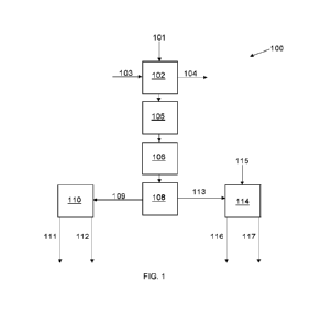
threshold. Deformation of the first central tube 154a attenuates at least a
portion of the
first force. A second crash energy management system 130a is disposed within
the draft
sill 102. The second crash energy management system 130b includes a third end
plate
(for example, the first end plate 150b), a fourth end plate (for example, the
second end
plate 152b), and a second central tube 154b disposed between the third end
plate and the
fourth end plate. The second central tube 154b is configured to deform in
response to a
second force exerted into the car coupling system 100 that exceeds a second
predetermined force threshold. Deformation of the second central tube 154b
attenuates at
least a portion of the second force.
CA 03222967 2023-12-08
WO 2023/018526
PCT/US2022/037665
[00105] In at least one embodiment, the first force equals the second force,
and
the first predetermined force threshold equals the second predetermined force
threshold.
In at least one other embodiment, the first force differs from the second
force, and the
first predetermined forced threshold differs from the second predetermined
force
threshold.
[00106] In at least one embodiment, one or both of the first crash energy
management system 130a or the second crash energy management system 130b is
interchangeable with a third crash energy management system 130n. For example,
the
third crash energy management system 130n replaces one of the first or second
crash
energy management systems 130a or 130b. As another example, the third crash
energy
management system 130n replaces both the first and second crash energy systems
130a
and 130b, such that the car coupling system 100 includes only one crash energy
management system 130, namely the crash energy management system 130n.
[00107] Various materials can be used to form the crash energy management
systems 130 depending on a desired force threshold upon which the crash energy
management systems 130 are to deform. For example, the crash energy management
systems 130 can be formed of steel, aluminum, or various other metals.
Additionally, the
crash energy management systems 130 can be sized and shaped for concertina
buckling,
as described herein, to provide an ideal energy attenuator. Moreover, a
material having a
particular yield strength, elongation characteristics, and/or the like can be
chosen
depending on the desired force threshold.
[00108] In at least one embodiment, mechanical properties such as yield
strength, tensile strength, and elongation may be used to tune deformation of
the crash
energy management systems 130 (such as the main central tubes 154 and/or any
supplemental tubes 170), as desired, such as to achieve specified trigger
forces and curve
quality. Further, in at least one embodiment, components of the crash energy
management systems 130 (such as the main central tubes 154 and/or any
supplemental
tubes 170) can be pre-deformed, such as to provide stability and desired
deformation
triggering.
21
CA 03222967 2023-12-08
WO 2023/018526
PCT/US2022/037665
[00109] Certain embodiments of the present disclosure provide a method of
forming a car coupling system for a rail vehicle. The method includes
disposing a crash
energy management system (such as any of those described herein) within a
draft sill. As
an example, the crash energy management system includes a first end plate, a
second end
plate, and a central tube disposed between the first end plate and the second
end plate.
The central tube is configured to deform in response to a force exerted into
the car
coupling system that exceeds a predetermined force threshold. Deformation of
the
central tube attenuates at least a portion of the force.
[00110] As another example, the crash energy management system includes a
front sub-assembly including a front end plate, guide legs extending between
the front
end plate and a front central plate, a front central tube extending between
the front end
plate and the front central plate, and stop walls coupled to the guide legs;
and a rear sub-
assembly coupled to the front sub-assembly including a rear end plate, a rear
central plate,
and a rear central tube extending between the rear end plate and the rear
central plate
(such as described with respect to Figures 18-24).
[00111] In at least one embodiment, the method further includes extending a
coupler outwardly from a first end of the draft sill, disposing a first stop
within the draft
sill, disposing a draft gear having a yoke within the draft sill. connecting
the coupler to
the draft gear, and disposing a second stop within the draft sill, wherein the
crash energy
management system is disposed between the draft gear and the second stop.
[00112] As a further example, the method includes disposing a supplemental
tube within an internal chamber of the central tube. As another or further
example, the
method includes disposing one or more supplemental tubes outside of the
central tube.
[00113] Figure 18 illustrates a perspective front lateral view of a crash
energy
management system 130, according to an embodiment of the present disclosure.
Figure
19 illustrates a perspective rear lateral view of the crash energy management
system 130
of Figure 18. Referring to Figures 18 and 19, the crash energy management
system 130
includes a first or front sub-assembly 300 coupled (such as secured) to a
second or rear
sub-assembly 302.
22
CA 03222967 2023-12-08
WO 2023/018526
PCT/US2022/037665
[00114] The front sub-assembly 300 includes a front end plate 304. Guide legs
306 extend from the front end plate 304 (such as rearwardly extending) at each
corner
308. In particular, forward ends 310 of the guide legs 306 extend from rear
corners
surfaces 312 of the front end plate 304. The guide legs 306 are separated from
each other
by spaces 314. Rear ends 316 of the guide legs 306 are secured to corner
exterior edges
of a central plate 318 (such as a first or front central plate). A central
tube 320 (for
example, a first or front central tube), such as any of those described
herein, extends
between the front end plate 304 and the central plate 318.
[00115] A stop wall 322 is coupled between neighboring guide legs 306. Each
side of the crash energy management system 130 includes a stop wall 322, as
shown in
Figures 18 and 19. For example, the crash energy management system 130
includes four
stop walls 322. In at least one embodiment, the stop walls 322 are flat,
planar panels.
Optionally, the crash energy management system 130 may include less than four
stop
walls 322.
[00116] Each stop wall 322 includes a forward end 324 secured between
interior edge surfaces 326 of neighboring guide legs 306. For example, the
forward ends
324 can be welded to the interior edge surfaces 326. Each stop wall 322 also
includes a
rear end 328 that rearwardly extends toward the rear sub-assembly 302.
[00117] The rear sub-assembly 302 includes a rear end plate 330. A central
tube 332 (for example, a second of rear central tube), such as any of those
described
herein, extends between the rear end plate 330 and a central plate 334 (such
as a second
or rear central plate). As shown, the rear ends 328 of the stop walls 322
extend
rearwardly past the central plate 334.
[00118] In at least one embodiment, a recess pocket 336 is formed in each of
the stop walls 322. The recess pocket 336 exposes portions of outer edges of
the central
plates 318 and 334. The recess pockets 336 allow the central plates 318 and
334 to be
welded together at a weld line 338. Because the weld line 338 is within the
recess pocket
336, the weld line 338 does not outwardly extend past an outer surface of the
stop wall
322. As such, the weld line 338 does not extend into or past an outer envelope
of the
23
CA 03222967 2023-12-08
WO 2023/018526
PCT/US2022/037665
crash energy management system 130. Further, the stop walls 322 are secured to
the
central plates 318 and 334 at interior perimeter weld line 335 of the recess
pocket 336.
[00119] Figure 20 illustrates an axial cross-sectional view of a guide leg 306
secured to the central plate 318 of the front sub-assembly 300, according to
an
embodiment of the present disclosure. Referring to Figures 18-20, each guide
leg 306
has an L-axial cross-section including a first beam 340 connected to a second
beam 342,
which is orthogonal to the first beam 340. The first beam 340 is coupled to a
first edge
segment 344 of the central plate 318, and the second beam 342 is coupled to a
second
edge segment 346 (orthogonal to the first edge segment 344) of the central
plate 318. In
at least one embodiment, the guide legs 306 are configured to slide or
otherwise move
over the edge portions of the central plate 318 (and the central plate 334).
For example,
the guide legs 306 are configured to move over portions of the central plates
318 and 334
as the central tube 320 deforms.
[00120] Figure 21 illustrates a first side view of the crash energy management
system 130 of Figure 18. Figure 22 illustrates a cross-sectional view of the
crash energy
management system 130 through line 22-22 of Figure 21. Referring to Figures 21
and 22,
each of the central plates 318 and 334 is formed having half the thickness of
each of the
front end plate 304 and the rear end plate 330. The central plates 318 and 334
are
secured together such as via weld lines, as described herein, to form a full
thickness plate
having the same (or approximately the same) thickness as each of the front end
plate 304
and the rear end plate 330.
[00121] As shown, a central bore 360 is formed through the rear end plate 330.
The central bore 360 allows for the rear end plate 330 to be welded to an
inner diameter
362 of the central tube 332 at a weld line 363. Further, a central bore 364 is
formed
through the front end plate 304. The central bore 364 allows for the front end
plate 304
to be welded to an inner diameter 366 of the central tube 320 at a weld line
367.
[00122]
Similarly, a central bore 370 is formed through the central plate 334.
The central bore 370 allows for the central plate 334 to be welded to an inner
diameter
372 of the central tube 332 at a weld line 373. Further, a central bore 374 is
formed
24
CA 03222967 2023-12-08
WO 2023/018526
PCT/US2022/037665
through the central plate 318. The central bore 374 allows for the central
plate 334 to be
welded to an inner diameter 376 of the central tube 320 at a weld line 377.
[00123] It has been found that welding the respective plates to the inner
diameters of the central tubes 320 and 332 enhances performance of the crash
energy
management system 130. For example, testing has demonstrated desired
deformation of
the central tubes 320 and 332, as described herein. Further, by forming each
of the
central plates 318 and 334 as half thickness plates, the central tube 320 can
be welded to
the central plate 318, and the central tube 334 can be welded to the central
plate 334, after
which the front sub-assembly 300 can then be welded to the rear sub-assembly
302. If,
however, a full thickness central plate were used, the manufacturing process
would be
more complicated, as the process of welding a second central tube thereto
would be more
difficult.
[00124] Alternatively, central bores may not be formed in at least one of the
front end plate 304, the rear end plate 330, the central plate 318, and/or the
central plate
334. Also, alternatively, a full thickness central plate may be used, instead
of half
thickness central plates secured to one another.
[00125] Figure 23 illustrates a second side view of the crash energy
management system 130 of Figure 18. Figure 24 illustrates a cross-sectional
view of the
crash energy management system 130 through line 24-24 of Figure 23. In at
least one
embodiment, a height 380 of the first side of the crash energy management
system 130
may be different than a height 382 of the second side of the crash energy
management
system 130. Optionally, the height 380 may equal the height 382.
[00126] Referring to Figure 18-23, when a force that exceeds a predetermined
force threshold is exerted into the car coupling system in the direction of
arrow A, the
central tubes 320 and 332 deform, thereby absorbing and attenuating the energy
of the
force, as describe herein (such as with respect to Figure 8). The central
tubes 320 and
332 may deform simultaneously, or the central tube 320 may deform before the
central
tube 332 deforms (or vice versa).
CA 03222967 2023-12-08
WO 2023/018526
PCT/US2022/037665
[00127] Unlike the central tubes 320 and 332, the guide legs 306 and the stop
walls 322 are not configured to deform. Instead, as the central tubes 320 and
332 deform,
the guide legs 306 ride over the outer edges of the central plates 318 and 334
moving
toward the rear end plate 330, and providing guidance during deformation. The
guide
legs 306 ride over the central plates 318 and 334, and rear edges 390 of the
guide legs
306 move toward and/or into a flush position with the rear edges 392 of the
stop walls
322. Further, as the central tube 332 deforms, the rear edges 390 of the guide
legs and
the rear edges 392 of the stop walls 322 move into an abutting relationship
with the rear
end plate 330. As noted, the deformation of the central tubes 320 and 332 may
occur
simultaneously, such that the two stage movement described herein occurs
simultaneously, or a first stage of motion that includes the deformation of
the central tube
320 (and resulting motion of the guide legs 306) occurs before (or after) the
deformation
of the central tube 332.
[00128] The guide legs 306 and the stop walls 322 provide guidance for motion
of the crash energy management system 130 as the central tubes 320 and 332
deform,
thereby eliminating, minimizing, or otherwise reducing a potential of rotation
or lateral
movement of the crash energy management system 130. Instead, force exerted
into the
crash energy management system 130 is controlled by the guide legs 306 and the
stop
walls 322 to be longitudinal in the direction of arrow 388. Even if a force is
exerted into
the crash energy management system 130 is not purely longitudinal, the guide
legs 306
and the stop walls 322 ensure that the motion of the crash energy management
system
130 during deformation of the central tubes 320 and 332 is constrained to
longitudinal
motion.
[00129] The rigid guide legs 306 and the stop walls 322, which are not
configured to deform (as do the central tubes 320 and 332) effectively turn
the front sub-
assembly 300 into an expanded length plate having a thickness greater than the
end plates
304 and 330. Further, the guide legs 306 and the stop walls 322 provide for
such an
expanded plate with far less material than if a monolithic plate having an
expanded
thickness were used. The guide legs 306 and stop walls 322 therefore resist
rotational
motion and lateral motion (which may otherwise compromise a desired
deformation of
26
CA 03222967 2023-12-08
WO 2023/018526
PCT/US2022/037665
central tubes and provide an undesirable force-travel curve), and ensure that
forces
exerted into the crash energy management system 130 are translated into purely
longitudinal motion.
[00130] The crash energy management system 130 having the front sub-
assembly 300 coupled to the rear sub-assembly 302, as described herein,
provides force
conditioning (that is, guidance) configured to convert non-longitudinal force
into pure,
longitudinal motion of the crash energy management system 130. The guide legs
306
and the stop walls 322 provide enhanced resistance to rotation and lateral
shifting as the
central tubes 320 and 332 deform.
[00131] In at least one embodiment, the central tubes 320 and 332 are
configured the same as the central tube 154, which is shown and described with
respect to
Figures 5-8. In particular, in at least one embodiment, the central tubes 320
and 332 are
hollow, having an internal chamber. In order to achieve concertina buckling
upon
deformation, the ratio of the length to outer diameter of the central tubes
320 and 332 is
2:1. Further, in order to achieve concertina buckling, the ratio of the outer
diameter to
the wall thickness of the central tubes 320 and 332 is 8:1. Alternatively, the
outer tube
of each of the central tubes 320 and 332 can be sized and shaped differently
so as not to
provide concertina buckling.
[00132] In at least one embodiment, one or both of the central tubes 320
and/or
332 can includes a supplemental tube, such as the supplemental tube 170 shown
in Figure
9. That is, one or both of the central tubes 320 and/or 332 can be configured
as shown
and described with respect to Figure 9.
[00133] In at least one embodiment, one or both of the front sub-assembly 300
and/or the rear sub-assembly 302 can include one or more supplemental tubes
outside of
the central tubes 320 and 332. For example, supplemental tubes can be disposed
proximate to the guide legs 306, such as described with respect to Figures 10
and 11.
[00134] The crash energy management system 130 shown and described with
respect to Figures 18-24 can be used with the modular car coupling system
shown and
27
CA 03222967 2023-12-08
WO 2023/018526
PCT/US2022/037665
described with respect to Figure 14. The crash energy management system 130
shown
and described with respect to Figures 18-24 is configured to be disposed
within a draft
sill, such as the draft sill 102 shown and described with respect to Figures
3, 4, 14, and 15.
[00135] Further, the disclosure comprises embodiments according to the
following clauses:
[00136] Clause 1. A crash energy management system configured to be
disposed within a draft sill of a car coupling system for a rail vehicle, the
crash energy
management system comprising:
a front sub-assembly including a front end plate, guide legs extending between
the
front end plate and a front central plate, a front central tube extending
between the front
end plate and the front central plate, and stop walls coupled to the guide
legs; and
a rear sub-assembly coupled to the front sub-assembly, wherein the rear sub-
assembly includes a rear end plate, a rear central plate, and a rear central
tube extending
between the rear end plate and the rear central plate.
[00137] Clause 2. The crash energy management system of Clause 1, wherein
the guide legs extend from the front end plate at corners.
[00138] Clause 3. The crash energy management system of Clauses 1 or 2,
wherein each of the stop walls comprises:
a forward end secured between interior edges surfaces of neighboring ones of
the
guide legs; and
a rear end that extends toward the rear sub-assembly.
[00139] Clause 4. The crash energy management system of any of Clauses 1-
3, wherein one or more of the stop walls comprises a recess pocket that
exposes one or
more weld lines of the front central plate and the rear central plate.
28
CA 03222967 2023-12-08
WO 2023/018526
PCT/US2022/037665
[00140] Clause 5. The crash energy management system of any of Clauses 1-
4, wherein the stop walls are welded to the front central plate and the rear
central plate.
[00141] Clause 6. The crash energy management system of any of Clauses 1-
5, wherein one or more of the guide legs includes a first beam connected to a
second
beam, which is orthogonal to the first beam.
[00142] Clause 7. The crash energy management system of any of Clauses 1-
6, wherein the guide legs are configured to move over portions of the front
central plate
and the rear central plate as the front central tube deforms.
[00143] Clause 8. The crash energy management system of any of Clauses 1-
7, wherein each of the front central plate and the rear central plate is half
the thickness of
each of the front end plate and the rear end plate.
[00144] Clause 9. The crash energy management system of Clause 8, wherein
the front central plate is welded to the rear central plate.
[00145] Clause 10. The crash energy management system of any of Clauses 1-
9, wherein one or both of the front end plate or the front central plate
comprises a front
central bore that allows for welding to an inner diameter of the front central
tube, and
wherein one or both of the rear end plate or the rear central plate comprises
a rear central
bore that allows for welding to an inner diameter of the rear central tube.
[00146] Clause 11. The crash energy management system of any of Clauses 1-
10, wherein each of the front central tube and the rear central tube has a
length, an outer
diameter, and a wall thickness, wherein a ratio of the length to the outer
diameter is 2:1,
and wherein a ratio of the outer diameter to the wall thickness is 8:1.
[00147] Clause 12. A method of forming a car coupling system for a rail
vehicle, the method comprising:
disposing a crash energy management system within a draft sill, wherein the
crash
energy management system comprises:
29
CA 03222967 2023-12-08
WO 2023/018526
PCT/US2022/037665
a front sub-assembly including a front end plate, guide legs extending
between the front end plate and a front central plate, a front central tube
extending
between the front end plate and the front central plate, and stop walls
coupled to
the guide legs; and
a rear sub-assembly coupled to the front sub-assembly, wherein the rear
sub-assembly includes a rear end plate, a rear central plate, and a rear
central tube
extending between the rear end plate and the rear central plate.
[00148] Clause 13. The method of Clause 12, further comprising:
extending a coupler outwardly from a first end of the draft sill;
disposing a first stop within the draft sill;
disposing a draft gear having a yoke within the draft sill;
connecting the coupler to the draft gear; and
disposing a second stop within the draft sill, wherein the crash energy
management system is disposed between the draft gear and the second stop.
[00149] Clause 14. A car coupling system for a rail vehicle, the car coupling
system comprising:
a draft sill;
a coupler extending outwardly from a first end of the draft sill;
a first stop within the draft sill;
a draft gear having a yoke within the draft sill, wherein the coupler connects
to the
draft gear;
a second stop within the draft sill; and
CA 03222967 2023-12-08
WO 2023/018526
PCT/US2022/037665
a crash energy management system disposed between the draft gear and the
second stop within the draft sill, wherein the crash energy management system
comprises:
a front sub-assembly including a front end plate, guide legs extending
between the front end plate and a front central plate, a front central tube
extending
between the front end plate and the front central plate, and stop walls
coupled to
the guide legs; and
a rear sub-assembly coupled to the front sub-assembly, wherein the rear
sub-assembly includes a rear end plate, a rear central plate, and a rear
central tube
extending between the rear end plate and the rear central plate.
[00150] Clause 15. The car coupling system of Clause 14, wherein the guide
legs extend from the front end plate at corners.
[00151] Clause 16. The car coupling system of Clauses 14 or 15, wherein each
of the stop walls comprises:
a forward end secured between interior edges surfaces of neighboring ones of
the
guide legs; and
a rear end that extends toward the rear sub-assembly.
[00152] Clause 17. The car coupling system of any of Clauses 14-16, wherein
one or more of the stop walls comprises a recess pocket that exposes one or
more weld
lines of the front central plate and the rear central plate, and wherein the
stop walls are
welded to the front central plate and the rear central plate.
[00153] Clause 18. The car coupling system of any of Clauses 14-17, wherein
the guide legs are configured to move over portions of the front central plate
and the rear
central plate as the front central tube deforms.
[00154] Clause 19. The car coupling system of any of Clauses 14-18, wherein
each of the front central plate and the rear central plate is half the
thickness of each of the
31
CA 03222967 2023-12-08
WO 2023/018526
PCT/US2022/037665
front end plate and the rear end plate, and wherein the front central plate is
welded to the
rear central plate.
[00155] Clause 20. The car coupling system of any of Clauses 14-19, wherein
one or both of the front end plate or the front central plate comprises a
front central bore
that allows for welding to an inner diameter of the front central tube, and
wherein one or
both of the rear end plate or the rear central plate comprises a rear central
bore that allows
for welding to an inner diameter of the rear central tube.
[00156] As described herein, embodiments of the present disclosure provide
systems and methods for attenuating energy exerted into a car coupling system.
Further,
embodiments of the present disclosure provide systems and methods that absorb
energy
that exceeds a predetermined force threshold. Moreover, embodiments of the
present
disclosure provide efficient, effective, and low cost systems for absorbing
and attenuating
such energy.
[00157] While various spatial and directional terms, such as top, bottom,
lower,
mid, lateral, horizontal, vertical, front and the like may be used to describe
embodiments
of the present disclosure, it is understood that such terms are merely used
with respect to
the orientations shown in the drawings. The orientations may be inverted,
rotated, or
otherwise changed, such that an upper portion is a lower portion, and vice
versa,
horizontal becomes vertical, and the like.
[00158] As used
herein, a structure, limitation, or element that is "configured
to" perform a task or operation is particularly structurally formed,
constructed, or adapted
in a manner corresponding to the task or operation. For purposes of clarity
and the
avoidance of doubt, an object that is merely capable of being modified to
perform the
task or operation is not "configured to" perform the task or operation as used
herein.
[00159] It is to be understood that the above description is intended to be
illustrative, and not restrictive. For example, the above-described
embodiments (and/or
aspects thereof) may be used in combination with each other. In addition, many
modifications may be made to adapt a particular situation or material to the
teachings of
32
CA 03222967 2023-12-08
WO 2023/018526
PCT/US2022/037665
the various embodiments of the disclosure without departing from their scope.
While the
dimensions and types of materials described herein are intended to define the
parameters
of the various embodiments of the disclosure, the embodiments are by no means
limiting
and are exemplary embodiments. Many other embodiments will be apparent to
those of
skill in the art upon reviewing the above description. The scope of the
various
embodiments of the disclosure should, therefore, be determined with reference
to the
appended claims, along with the full scope of equivalents to which such claims
are
entitled. In the appended claims, the terms "including" and "in which" are
used as the
plain-English equivalents of the respective terms "comprising" and "wherein."
Moreover,
the terms "first," "second," and "third," etc. are used merely as labels, and
are not
intended to impose numerical requirements on their objects. Further, the
limitations of
the following claims are not written in means-plus-function format and are not
intended
to be interpreted based on 35 U.S.C. 112(f), unless and until such claim
limitations
expressly use the phrase "means for" followed by a statement of function void
of further
structure.
[00160] This written description uses examples to disclose the various
embodiments of the disclosure, including the best mode, and also to enable any
person
skilled in the art to practice the various embodiments of the disclosure,
including making
and using any devices or systems and performing any incorporated methods. The
patentable scope of the various embodiments of the disclosure is defined by
the claims,
and may include other examples that occur to those skilled in the art. Such
other
examples are intended to be within the scope of the claims if the examples
have structural
elements that do not differ from the literal language of the claims, or if the
examples
include equivalent structural elements with insubstantial differences from the
literal
language of the claims.
33