Note: Descriptions are shown in the official language in which they were submitted.
MULTI-HYBRID POWER GENERATOR SYSTEM AND METHOD
[0001] (Deleted)
Field of the Invention
[0002] The present invention relates generally to power systems, and
more
particularly, to an energy harvesting and storage system that employs a multi-
hybrid power
generator for harvesting and generating power from an interchangeable power
source.
Background of the Invention
100031 Today's news is full of media reports of global warming,
pollution and other
environmental hazards that are impacting the world's inhabitants. Dire
predictions are
being made about the environmental state of the world and its natural
resources. One focal
point of these reports is the worldwide generation, use, and consumption of
electricity. The
generation of electricity involves different kinds of resources such as coal,
oil, and natural
gas and the processing of the foregoing resources has been identified as a
source of
deleterious environmental effects that include pollution, acid rain, and
greenhouse effects.
Given the importance of electricity to everyday comforts including, but not
limited to,
heating, lighting, commtmications, transportation, and computing, and to
worldwide
industries and economies, it is unlikely that worldwide electricity demand
will slow in any
appreciable manner.
[0004] To combat some of the adverse environmental impacts, perceived
or
otherwise, of electricity generation, scientists, researchers, and industries
have recently
focused their efforts on alternative and/or renewable energy sources such as
solar power,
wind power, and tidal power. Wind power is present in certain countries that
are erecting
large wind farms or wind parks that consist of various numbers of wind
turbines spread out
over an extensive geographic area that is known to have regular and sustained
winds over
extended periods of time. The winds turn blades on the turbines that convert
the energy of
the wind into mechanical power. The mechanical power is then converted to
electricity
using generators. However, wind power does suffer from potential limitations
related to the
heavy reliance on
1
Date Regue/Date Received 2024-02-15
WO 2023/004121
PCT/US2022/038026
location, season, and weather to produce and maintain the necessary winds for
the electricity
generation. Further, the cost of acquiring the necessary real estate and
installation of the
plethora of wind turbines thereon can be very high and a barrier to market
entry.
[0005] Solar energy, another one of the above-identified
alternative energy sources, is
directed to harvesting energy from the sun that is converted into thermal or
electrical energy.
Typically, solar energy is harnessed in three main ways: using photovoltaics,
solar heating and
cooling, and concentrating solar power. Photovoltaics generate electricity
directly from
sunlight via an electronic process and it is typically associated with
powering small and/or
medium-sized applications ranging from single devices (e.g., a calculator) to
an off-grid home
powered by a photovoltaic array. Solar heating and cooling (SHC) and
concentrating solar
power (CSP) applications use both the heat generated by the sun to provide
space or water
heating (in the case of SHC systems), or to run traditional electricity-
generating turbines (in the
case of CSP power plants). This type of renewable energy is typically
characterized as either
passive solar or active solar and this energy technology can be built as a
distributed generation
model (e.g., located at or near the point of use) or as a central station
model (e.g., a utility-scale
solar power plant that is similar to traditional power plants). These energy
methods may also
store energy that is produced for distribution at some later time (e.g., after
the sun sets) using a
variety of solar storage technologies. These features have made solar power
one of the more
desirable alternative renewable energy sources. However, solar power has one
significant
potential drawback in that the technology in inherently intermittent in nature
and may be
subject to periods where the source sunlight is unavailable thereby making the
solar energy
produced therefrom unavailable. As such, this requires that generated solar
energy be stored in
batteries, thereby increasing the overall costs of pure solar energy systems.
[0006] Solar thermal usage is another form of solar energy. This
approach is similar to
traditional electricity generation in that the energy of the sun drives a
power plant, such that
electricity is produced indirectly. The solar thermal efforts have focused on
matching the
efficiencies of traditional power plants that burn fossil fuels, however, this
requires complex
devices, such as focusing concentrating mirrors to heat oil to very high
temperatures. Also, the
cost of designing, building, running, and maintaining solar thermal operating
plants is very
high. In addition to this financial challenge, finding a suitable geographical
location for such
solar thermal operating plants is a further challenge.
2
CA 03223410 2023- 12- 19
WO 2023/004121
PCT/US2022/038026
[0007] As noted previously, many of the renewable energy
technologies require some
type of energy storage capacity. Many systems and methods for energy storage
have been
developed. One such energy storage system pumps water into high elevated
reservoirs and
then releases the water through hydro-generators. Compressed air energy
storage systems
compress air with a compressor, and the compressed air is stored in a
geological formation
(e.g., a cavern, aquifer, etc.) or other structure where it can be drawn upon
when energy
demands require. Typically, the compressed air mixes with natural gas,
combusts and expands
through a turbine to generate mechanical power that drives an electric
generator to generate
electricity. Mechanical gearboxes are used to convert the speed and torque
from the power
source (e.g., a renewable energy source) to interface with the electrical
generator. However,
mechanical gearboxes require substantial maintenance and tend to deteriorate
faster than the
systems they support. Direct drive generators can eliminate the need for these
expensive
mechanical gearboxes, but the complexity and associated maintenance of direct
drive
generators make them no less of a cost burden. Such compressed air energy
systems are also
challenged by geographic constraints and using fixed volume of geological
formations, and
therefore typically operate at high variable pressures during energy storage
and retrieval. This
high variable pressure need decreases the efficiency of the compressor and the
turbine, which
operate at an optimal performance at a single design pressure.
[0008] While various energy storage solutions exist, these
systems have certain
disadvantages that include energy losses during the conversion process, the
use of water
reservoirs that require large geographical footprints, are expensive to
construct, limitations as
to the amount of energy that can be stored, and the dissipation of stored
energy over time.
Further, converting pressurized air back to electricity is a complicated and
inefficient process.
[0009] Another type of energy system is the hybrid energy
system. Hybrid energy
systems are defined as the integration of several types of energy generation
equipment, such as
electrical energy generators, electrical energy storage systems, and renewable
energy sources.
A hybrid energy system, or hybrid power, usually includes of two or more
renewable energy
sources used together to provide increased system efficiency as well as
greater balance in
energy supply. Hybrid systems combine two or more modes of electricity
generation together,
for example, using renewable technologies such as solar photovoltaic (PV) and
wind turbines.
Hybrid systems provide a high level of energy security through the mix of
generation methods,
3
CA 03223410 2023- 12- 19
WO 2023/004121
PCT/US2022/038026
and can incorporate a storage system (e.g., battery, fuel cell) or small
fossil fueled generator to
ensure maximum supply reliability and security. The basic components of such
systems are
power sources (e.g., wind turbine, diesel engine generator and solar arrays),
and the battery and
the power management center, which regulates power production from each of the
sources.
The advantages of hybrid energy systems include the provision of power on a
continual basis
without any interruption, as the batteries connected therein store energy for
later use, these
batteries also increase the utilization of the renewable energy sources, lower
maintenance costs,
provide higher efficiency, and improved load management. The disadvantages of
hybrid
energy systems include increased process control complexity given the
different energy source
types and their interaction and coordination must be precisely controlled,
higher installation
costs, battery life and the overall load capacity that can be connected to the
system.
[0010] Accordingly, there is need for multi-hybrid power
generator system that
improves energy harvesting, generation, and storage from an interchangeable
power source.
Summary of the Invention
[0011] The present invention is directed to a multi-hybrid power
generator and system
that facilitates energy harvesting, generation, and storage from
interchangeable power sources.
[0012] In a first implementation of the invention, a multi-
hybrid power generator
system for harvesting energy from an interchangeable power source is provided
including one
or more battery banks electrically connected to receive and store energy from
an
interchangeable power source in hydraulic electrical actuation devices (HEADs)
that are
initially powered by one or more battery banks. The HEADs drive mechanical
energy through
pistons to piston rods, each having a pair of retracting springs connected
thereto. The piston is
located within a hydraulic chamber. The system also includes a crankshaft
driven by the
pistons and an intelligent power controller communicatively coupled to at
least one electrical
load and to a number of power management devices. The intelligent power
controller controls
energy monitoring, energy generation, energy distribution, and energy storage
between the
battery banks, the electrical load, the interchangeable power source, and the
HEADs.
[0013] In a second implementation of the invention, a method for
providing power using
a multi-hybrid power generator system is provided. The method includes
controlling a first
subset of HEADs of the multi-hybrid power generator system to power a first
power generator,
4
CA 03223410 2023- 12- 19
WO 2023/004121
PCT/US2022/038026
controlling a second subset of HEADs to power a second power generator,
controlling both the
first subset and the second subset of HEADs in unison to drive the first power
generator and the
second power generator, and alternating among the three previous steps of
controlling to provide
efficient energy generation and to keep a portion of the multi-hybrid power
generator system in
a cooling cycle mode.
[0014] In a second implementation of the invention, a multi-
hybrid power generator
system is provided including one or more battery banks electrically connected
to receive and
store energy from an interchangeable power source in HEADs that are initially
powered by the
battery bank. The HEADs drive mechanical energy through pistons to piston
rods, each having
a pair of retracting springs connected thereto. Each retracting spring is made
of a spring material
and is balanced at an operating angle to increase the effect of the piston on
the crankshaft. The
piston is disposed within a hydraulic chamber. The system also includes an
intelligent power
controller communicatively coupled to an electrical load and to a number of
power management
devices. The intelligent power controller controls energy monitoring, energy
generation, energy
distribution, and energy storage between the battery banks, the electrical
load, the
interchangeable power source, and the HEADs.
[0015] These and other objects, features, and advantages of the
present invention will
become more readily apparent from the attached drawings and the detailed
description of the
preferred embodiments, which follow.
Brief Description of the Drawings
[0016] The preferred embodiments of the invention will
hereinafter be described in
conjunction with the appended drawings provided to illustrate and not to limit
the invention,
where like designations denote like elements, and in which:
[0017] FIG. 1 presents a schematic of a multi-hybrid power
generator system in
accordance with an embodiment of the invention.
[0018] FIG. 2 presents a perspective view of a crankshaft for
use in the multi-hybrid
power generator system of FIG. 1 in accordance with an embodiment of the
invention.
[0019] FIG. 3 presents a perspective view of a gearbox for use
in the multi-hybrid
power generator system of FIG. 1 in accordance with an embodiment of the
invention.
[0020] FIGS. 4A presents a perspective view of an illustrative
engagement between the
CA 03223410 2023- 12- 19
WO 2023/004121
PCT/US2022/038026
crankshaft of FIG. 2 and the gearbox of FIG. 3 for use in the multi-hybrid
power generator
system of FIG. 1 in accordance with an embodiment of the invention, and
showing the location
of retracting springs.
[0021] FIG. 4B presents a front view of an illustrative
engagement between the
crankshaft and the gearbox, and showing an alternative configuration of the
retracting springs
according to an embodiment of the invention.
[0022] FIG. 4C presents a side view of the portion of the system
of FIG. 4B.
[0023] FIG. 5 presents an illustrative intelligent power
controller configured for use in
the multi-hybrid power generator system of FIG. 1 in accordance with an
embodiment of the
invention.
[0024] FIG. 6 presents an illustrative architecture for a multi-
hybrid power generation
application for use with the multi-power generator system of FIG. 1 in
accordance with an
embodiment of the invention.
100251 FIG. 7 presents an illustrative power management device
configured for use in
the multi-hybrid power generator system of FIG. 1 in accordance with an
embodiment of the
invention.
[0026] FIG. 8 presents a flowchart of operations for harvesting
energy from an
interchangeable power source using the multi-hybrid power generator system of
FIG. 1 in
accordance with an embodiment of the invention.
[0027] Like reference numerals refer to like parts throughout
the several views of the
drawings.
Detailed Description
[0028] The following detailed description is merely exemplary in
nature and is not
intended to limit the described embodiments or the application and uses of the
described
embodiments. As used herein, the word "exemplary" or "illustrative" means
"serving as an
example, instance, or illustration." Any implementation described herein as
"exemplary" or
"illustrative- is not necessarily to be construed as preferred or advantageous
over other
implementations. All the implementations described below are exemplary
implementations
provided to enable persons skilled in the art to make or use the embodiments
of the disclosure
and are not intended to limit the scope of the disclosure, which is defined by
the claims. For
6
CA 03223410 2023- 12- 19
WO 2023/004121
PCT/US2022/038026
purposes of description herein, the terms "upper", "lower", "left", "rear",
"right", "front",
"vertical", "horizontal", and derivatives thereof shall relate to the
invention as oriented in the
Figures herein. Furthermore, there is no intention to be bound by any
expressed or implied
theory presented in the preceding technical field, background, summary, or the
following
detailed description. It is also to be understood that the specific devices
and processes
illustrated in the attached drawings, and described in the following
specification, are simply
exemplary embodiments of the inventive concepts defined in the appended
claims. Hence,
specific dimensions and other physical characteristics relating to the
embodiments disclosed
herein are not to be considered as limiting, unless the claims expressly state
otherwise.
[0029] Shown throughout the figures, the present invention is
directed to a multi-hybrid
power generator and system that facilitates energy harvesting, generation, and
storage from
interchangeable power sources.
[0030] FIG. 1 presents a schematic of a multi-hybrid power
generator system 100 in
accordance with an embodiment of the present invention. As shown for instance
in FIG. 1, the
multi-hybrid power generator system 100 includes a plurality of battery banks
(i.e., battery
bank 1102, battery bank 2 104 and battery bank 3 106). The plurality of
battery banks is
matched with the type of energy to be harvested from interchangeable power
source 108 for,
among other things, providing power to at least one electrical load 116, which
is shown
illustratively as a home that has an electrical load to run the household
devices, for example.
The plurality of battery banks (i.e., battery bank 1 102, battery bank 2 104
and battery bank 3
106) may be one of several different types of batteries including but not
limited to lead acid,
lithium ion, nickel cadmium (NiCd), nickel iron (NiFe), saltwater or absorbed
glass mat
(AGM). In accordance with an embodiment, battery bank 1102, battery bank 2 104
and
battery bank 3 106 are all the same type (e.g., NiCd) and are of a
substantially equal size and
capacity. While three battery banks are illustrated, more or fewer than three
battery banks may
be utilized without departing from the broader aspects of the invention. In
accordance with the
embodiments herein, the interchangeable power source 108 may be any natural,
alternative
and/or renewable energy power source including, but not limited to, solar
power, wind power,
or hydropower. For example, as shown in FIG. 1, the interchangeable power
source is solar
power using a plurality of photovoltaic (PV) solar panels (i.e., PV solar
panel 110-1, PV solar
panel 110-2, PV solar panel 110-3 and PV solar panel 110-4), with each PV
solar panel
7
CA 03223410 2023- 12- 19
WO 2023/004121
PCT/US2022/038026
including a plurality of photovoltaic cells 112. Illustratively, each of the
PV solar panels may
be configured as a 12- volt, 1.5-amp panel, taking into consideration the
requirement of
powering the at least one electrical load 116. As will be readily understood,
a photovoltaic
panel is comprised of numerous photovoltaic cells, with each cell having the
ability to convert
sunlight into electricity. In accordance with the principles of the
embodiments disclosed
herein, the multi-hybrid power generation system 100 will harvest, generate,
store and supply
energy without the need for any fossil fuels, thereby providing for a clean
energy footprint as
compared to other power generation systems.
[0031] As shown in FIG. 1, multi-hybrid power generator system
100 further includes a
plurality of power management hydraulic electrical actuation devices (HEADs)
(i.e., READ
116- 1, READ 116-2, READ 116-3, and HEAD116-4), and each power management
device
includes at least one sensor unit (e.g., sensor unit 616, See FIG. 7) for
measuring power at any
given time, at least one inverter unit (e.g., inverter unit 614; See FIG. 7)
for changing direct
current (DC) to alternating current (AC) and at least one energy router unit
(e.g., energy router
unit 612; See, FIG. 7) for managing power distribution. Each power management
device is
further communicatively coupled, via communication link 150, to an intelligent
power
controller 118. The intelligent power controller 118 is communicatively
coupled to the
electrical load 116 and to the plurality of power management devices for
selectively controlling
power monitoring, power generation, power distribution, and power storage
between or to the
plurality of battery banks (i.e., battery bank 1102, battery bank 2 104 and
battery bank 3 106),
the at least one electrical load 116 and the plurality of HEADs (i.e., HEAD
116-1, HEAD
116-2, HEAD 116-3, and READ 116-4). The configuration of the plurality of
HEADs as
depicted in FIG. 1 is one of various configurations that may be used in
accordance with the
principles of the disclosed embodiments.
[0032] Referring to FIG. 1, in accordance with an embodiment,
the output of the
interchangeable power source 108, for example, the energy output of the
plurality PV solar
panels (i.e., PV solar panel 110-1, PV solar panel 110-2, PV solar panel 110-3
and PV solar
panel 110-4) is harnessed through the SIR 114-1 and transferred to the first
battery bank 102,
thereby providing an immediate power storage option. In this way, the first
battery bank 102 is
electrically connected to receive and store energy from the interchangeable
power source 108,
and the first battery bank 102 is electrically connected to a first power
management device (i.e.,
8
CA 03223410 2023- 12- 19
WO 2023/004121
PCT/US2022/038026
power management unit 114-1) and a second power management device (i.e., power
management unit 114-2) of the plurality of power management devices. As
necessary, the
inverter unit 614 of the HEAD 116-1 inverts the direct current (e.g.,
delivered by the plurality
of PV solar panels) to alternating current. Further, this power stored in the
first battery bank
102 is managed by the second power management unit 114-2 and is used to
initially power a
multi-hybrid generator 148 including the plurality of HEADs (i.e., HEAD 116-1,
HEAD 116-2,
HEAD 116-3 and HEAD 116-4). The HEADs are used to convert a source energy
(e.g.,
electrical energy) into mechanical/hydraulic motion. In an embodiment, each
HEAD includes
a hydraulic-electric pump. In a further embodiment, each HEAD includes an
electrical
actuator.
[0033] The plurality of HEADs, as initially powered by the first
battery bank 102, will
drive mechanical energy through a combination of a plurality of pistons (i.e.,
piston 120-1,
piston 120- 2, piston 120-3 and piston 120-4) and a plurality of piston rods
(i.e., piston rod 122-
1, piston rod 122-2, piston rod 122-3 and piston rod 122-4). The first piston
120-1 is located
within a first hydraulic chamber 130-1 of a plurality of hydraulic chambers
and is mechanically
connected to the first piston rod 122-1 of the plurality of piston rods. In
turn, this mechanical
energy is transferred to a first crankshaft 124 and a second crankshaft 126,
respectively (each
crankshaft configured as shown in crankshaft 200 of FIG. 2). Each of the first
crankshaft 124
and second crankshaft 126 have a respective driving gear 206 that is located
at a respective
center point 212 along the respective crankshaft (depicted in detail in FIG.
2). In turn, the first
drive gear 206 of the first crankshaft 124 is mechanically connected to a
first set of gears 134
of a first gearbox 132, and the second drive gear 206 of the second crankshaft
126 is
mechanically connected to a second set of gears 140 of a second gearbox 138.
Each gearbox
and respective set of gears are configured as shown in gearbox 300 of FIG. 3,
as further
detailed herein below.
[0034] The first HEAD 116-1 of the plurality of HEADs provides a
hydraulic force that
drives the first piston 120-1 of the plurality of pistons (and the respective
piston 122-1) and the
first piston 120-1 has a first pair of retracting springs 128 connected
thereto (depicted in detail
in FIGS. 4B and 4C). The upward force during the retraction of the first HEAD
116-1 is
supported by the first pair of retracting springs 128 that run along the
outside of the first HEAD
116-1 that is driving the first piston 120-1 such that the first pair of
retracting springs 128
9
CA 03223410 2023- 12- 19
WO 2023/004121
PCT/US2022/038026
support an upward motion (along upward direction 146) during the retraction of
the first HEAD
116-1 and returning of the first piston 120-1 back to an original position.
Each of the other
HEADs (i.e., HEAD 116-2, 116-3 and 116-4) have a corresponding pair of
retracting springs
128 that function in the same manner. In this way, each corresponding piston-
to-piston rod
combination set has a pair of retracting springs 128 that run along their side
that assist in the
retracting of the piston from a corresponding down stroke (along downward
direction 144)
thereby significantly increasing the overall efficiency of the multi-hybrid
generator 148 and the
multi-hybrid generator system 100 The retracting springs 128 increase the
efficiency of the
pistons by decreasing the work of the piston, specifically on the upstroke,
working against the
force of gravity. It will be appreciated that while retracting springs 128 are
shown as a pair
there are any number of further embodiments that may include different numbers
of springs.
[0035] In an embodiment, the retracting springs are fabricated
using a specially
formulated spring alloy composed of approximately 55% high carbon steel, 24%
titanium (Ti),
and 21% vanadium (V). This formulation supports an anti-gravity effect thereby
increasing
overall efficiency of the respective crankshafts. Further, the density of the
material (See,
equation (1), herein below) impacts the efficacy of the spring (e.g., spring
efficiency). The
embodiments herein call for an alloy with specific strength, malleability,
torsion strain/stress
resistance, and heat dissipation. In an embodiment, the natural frequency of
the retracting
spring is approximately twenty (20) times the frequency of application of a
periodic load. This
avoids resistance with all harmonic frequencies up to the twentieth (20th)
order. In an
embodiment, the natural frequency of the retracting springs 128, as configured
in FIG. 1, is
given by equation (1):
(1) Fn = (d/27rxD2xn)-A6Gxg/r3);
where:
d = Diameter of the wire;
D = Mean diameter of the spring;
n = Number of active turns;
G = Modulus of rigidity;
g = Acceleration due to gravity; and
(3 = Density of the material of the spring.
[0036] It will be understood that above-identified spring alloy
formulation is only one
CA 03223410 2023- 12- 19
WO 2023/004121
PCT/US2022/038026
such formulation that may be used consistent with the principles of the
disclosed embodiments
herein.
100371 Further, the modified coefficient of linear expansion (a)
(See, equation (2)
herein, below) of the specially formulated spring alloy is an important
feature of the retracting
springs 128, because when an object is heated or cooled the object's length
changes by an
amount proportional to the object's original length and the change in
temperature. Thus, given
the expected high pressure and high heat generated by the multi-hybrid
generator 148 and its
constituent components, this coefficient is an important design consideration.
In accordance
with an embodiment, the linear thermal expansion change in length of the
retracting springs
128 is given by equation (2):
(2) AL = LO x a x (to¨ ti);
where.
AL = change in length of the object;
LO = Original length of the object;
a = modified coefficient of linear expansion with the special alloy materials
has altered this co-
efficient increasing resistance against gravity in the upstroke of the
crankshaft;
to = initial temperature; and
ti = final temperature.
100381 Each HEAD disclosed herein specifically addresses the
hydraulic and reverse
spring motion (i.e., anti-gravity displacement) upward forces on the upstroke
that yield the
specific required output on the drive gear of the crankshaft. An optimum
needed torque output
on the drive gear (at the center of the crankshaft) is required for the system
to have a final
output of electricity production with more than 76% efficiency (converting
energy in the form
of electricity/pressure to mechanical energy/torque). A Hydraulic Electrical
Actuation
Constant Optimum Efficiency (HEACOE) is defined by formula (3):
(3) F/t(pV2/2o-O-FAAPg x 0.7/4h) = Constant;
where:
F = Force;
P = Pressure;
p = Density;
V = Velocity;
11
CA 03223410 2023- 12- 19
WO 2023/004121
PCT/US2022/038026
g = Gravitational force due to acceleration;
h = Height (discharge total);
at = Allowable tensile resistance,
= Coefficient; and
t = Time.
[0039] Further, the second HEAD 116-2 of the plurality of HEADs
drives a second
piston 120-2 of the plurality of pistons having a second pair of retracting
springs 128 connected
thereto, the second piston 120-2 being located within a second hydraulic
chamber 130-2 and
mechanically connected a second piston rod 120-2 of the plurality of piston
rods, and the first
piston rod 120-1 and the second piston rod 120-2 are connected to the first
crankshaft 124.
A third READ 116-3 of the plurality of HEADs drives a third piston 120-3 of
the plurality of
pistons having a third pair of retracting springs 128 connected thereto, the
third piston 120-3
being located within a third hydraulic chamber 130-3 and connected to a third
piston rod 122-3
of the plurality of piston rods. A fourth HEAD 116-4 of the plurality of HEADs
drives a fourth
piston 120-4 of the plurality of piston having a fourth pair of retracting
springs 128-4 connected
thereto, the fourth piston being located within a fourth hydraulic chamber 130-
4 and connected
to a fourth piston rod 122-4 of the plurality of piston rods. The third piston
rod 122-3 and the
fourth piston rod 122-4 are mechanically connected to the second crankshaft
126. In
accordance with an embodiment, the first crankshaft 124 is mechanically
connected through the
first drive gear to the first set of gears of the first gearbox 132, with the
first crankshaft also
including a first counterweight 202 and a second counterweight 204 connected
thereto
(depicted in detail in FIG. 2).
[0040] With further reference to FIGS. 4B and 4C, the retracting
springs 128 may be
configured as helical springs positioned inside the piston/hydraulic chambers
130-1, 130-2,
130-3, 130-4. In an embodiment, the springs 128 may be configured as tension
springs.
[0041] Referring to FIG. 2, a perspective view of a crankshaft
200 is shown for use in
the multi-hybrid power generator system 100 of FIG. 1 in accordance with an
embodiment.
The crankshaft 200 has a weighted separator support joint 208 mechanically
joining the first
crankshaft 124 and the second crankshaft 126. The weighted separator support
joint 208
separates and balances the first crankshaft 124 and the second crankshaft 126
to allow for the
independent operation of one from the other. Further, the first HEAD 130-1 and
the second
12
CA 03223410 2023- 12- 19
WO 2023/004121
PCT/US2022/038026
READ 130-2 form a first READ set or subset and the third HEAD 130-3 and the
fourth HEAD
130-4 form a second HEAD set or subset. Each HEAD set powers a respective
section of the
crankshaft 200 by mechanically driving their respective gearbox via the set of
gears specific
thereto. FIG. 3 presents a perspective view of a gearbox 300 for use in the
multi-hybrid power
generator system 100 of FIG. 1 in accordance with an embodiment of the
invention. Each of
the first gearbox 132 and the second gearbox 138 are configured the same as
the gearbox 300
including a set of gears 302. The HEADs are depicted in a straight in-line
orientation, but
alternate orientations including, but not limited to, V-shaped orientations,
may be utilized
without departing from the broader aspects of the invention.
[0042] As such, each crankshaft 200 (i.e., crankshaft 124 and
crankshaft 126) will
drive the respective gearboxes (i.e., gearbox 132 and gearbox 138,
respectively) by and
through the respective drive gear on the crankshaft that is mechanically
connected to the
respective set of gears (i.e., first set of gears 134 and second set of gears
140) such that the
efficiency of the multi-hybrid generator 148 and the multi-hybrid power
generator system 100
is increased and the multi-hybrid power generator 148 will operate at overall
lower/cooler
operating temperatures, given the independent operation of the crankshaft
sections in
accordance with the embodiment. As shown, in addition to the drive gear 206,
the crankshaft
200 includes a plurality of counterweights 210 inclusive of the first
counterweight 202 and the
second counterweight 204, as noted above. In an embodiment, a first
counterweight is
connected proximate to a point where the first piston 120-1 is connected to
the first crankshaft
124 and a second counterweight is connected proximate to a point where the
second piston
120-2 is connected to the first crankshaft 124. Similarly, a third
counterweight is connected
proximate to a point where the third piston 120-3 is connected to the second
crankshaft 126 and
a fourth counterweight is connected proximate to a point where the fourth
piston 120-4 is
connected to the second crankshaft 126. In this way, at each corresponding
point on the
crankshaft 200 where the plurality of piston rods move in a downward direction
144 there is a
corresponding counterweight that works in conjunction with the existing
gravitational forces
generated on the downstroke of the pistons in the downward direction 144. As
such, the
continuous motion of the plurality of piston rods on each crankshaft section
rotates and
mechanically drives its respective gearbox (i.e., the gearbox 132 or the
gearbox 138). The
mechanical downward movement of the plurality of HEADs, as described herein,
in
13
CA 03223410 2023- 12- 19
WO 2023/004121
PCT/US2022/038026
conjunction with the downward gravitational forces on the counterweights
increases the
efficiency of such piston downstrokes as a function of both crankshaft torque
and rotational
efficiency. Similarly, the upward direction 146 movement of the plurality of
HEADs in
conjunction with the respective pairs of retracting springs supporting such
upward movement
and associated forces will increase the efficiency of the upwards strokes of
the plurality of
pistons as a function of crankshaft torque and rotation as well as the overall
efficiency of the
plurality of HEADs, both collectively and individually. In an embodiment, the
force generated
by the downstroke of each piston is approximately 16 pounds per square inch.
This allows a
set or subset of HEADs to operate with approximately 26 pounds per square inch
of pressure
with alternating subsets of two heads moving to downstroke in unison. The
operation of the
READ subsets allows to pressure to remain variable depending on the
application and/or
system needs.
100431 Turning back to FIG. 1, the second crankshaft 126 is
mechanically connected to
the second generator 142, via its respective second drive gear that is
mechanically connected to
the second set of gears 140 of the second gearbox 138, and includes a third
counterweight and a
fourth counterweight connected thereto. Thus, each respective gearbox system
mechanically
drives the respective generator connected thereto. The first HEAD 116-1 and
the second
READ 116-2 ultimately drive the first set of gears 134 of the first gearbox
132 for powering a
first generator 136 (depicted in detail in FIG. 3). In this way, the first
generator 136 is
mechanically connected to the first gearbox 132 and communicatively connected
to a third
power management device 114-3 of the plurality of power management devices for
the
supplying of electrical power to the second battery bank 104 (i.e., battery
bank 2 104) of the
plurality of battery banks. The second battery bank 104 of the plurality of
battery banks is
electrically connected to receive and store energy from the first generator
136 that is managed
by the third power management device 114-3 of the plurality of power
management devices
that is electrically thereto. Similarly, the third HEAD 116-3 and the fourth
HEAD 116-4
ultimately drive the second set of gears 140 of the second gearbox 138 for
powering a second
generator 142 (depicted in detail in FIG. 3). The second generator 142 is
electrically connected
to and supplies electrical power to the third battery bank (i.e., battery bank
3 106) of the
plurality of battery banks. The third battery bank 106 of the plurality of
battery banks is
electrically connected to receive and store energy from the second generator
142 such that the
14
CA 03223410 2023- 12- 19
WO 2023/004121
PCT/US2022/038026
third battery bank is electrically connected to the fourth power management
device 114-4 of the
plurality of power management devices for such purposes. The second generator
142 is
mechanically connected to the second gearbox 138 and communicatively connected
to the
fourth power management device 114-4 of the plurality of power management
devices as well.
A fifth power management device 114-5 is communicatively coupled to the
battery bank 104
and the battery bank 106 for managing power therebetween. In accordance with
an
embodiment, and at the direction of the intelligent power controller 118, the
battery bank 104
and the battery bank 106 may supply power either simultaneously or
alternatively to both the
plurality of BEADs and the at least one electrical load 116 to optimize the
overall efficiency of
the multi-hybrid power generator system 100. Advantageously, the ability to
mechanically
drive the respective gearboxes either synchronously, independently, or
alternatively
significantly increases the efficiency and the durability of the multi-hybrid
power generator
system 100 by avoiding continuous mechanical motion without some defined
resting period.
100441 In accordance with the disclosed embodiments, the first
battery bank 102
initially powers the plurality of HEADS 116-1, 116-2, 116-3, 116-4 that in
turn mechanically
power the respective piston/piston rod combinations. The piston/piston rod
combinations
mechanically power a respective drive gear of a respective crankshaft with
each drive gear
mechanically powering a respective set of gears of a respective gear box. Each
gear box in turn
mechanically powers a respective generator that generates electrical power
that is supplied to
and stored by multiple battery banks (e.g., battery banks 104, 106) that
further satisfies at least
one electrical load (e.g., a home). This is further illustrated in FIGS. 4A-
4C, which presents a
perspective view of an illustrative engagement 400 between the crankshaft of
FIG. 2 and the
gearbox of FIG. 3, for use in the multi-hybrid power generator system of FIG.
1 in accordance
with an embodiment of the invention. As shown, and as detailed above, the
first driving gear
206 of the first crankshaft 124 are engaged and in similar fashion, the second
driving gear 206
of the second crankshaft 126 are engaged, such that the piston/piston rod
combinations
mechanically power the respective drive gear of the respective crankshaft with
each drive gear
mechanically powering a respective set of gears of a respective gear box
(i.e., the first gearbox
132 and the first set of gears 134, and the second gearbox 138 and the second
set of gears 140).
Each gear box in turn mechanically powers a respective generator (i.e., the
first generator 136
and the second generator 142) that generates electrical power that is supplied
to and stored by
CA 03223410 2023- 12- 19
WO 2023/004121
PCT/US2022/038026
multiple battery banks, that further satisfies at least one electrical load
(e.g., a home). As best
shown in FIG. 2, the first driving gear 206 is located at a first center point
212 along the first
crankshaft 124, and is mechanically connected to the first set of gears 134 of
the first gear box
132 for driving the first set of gears 134 of the first gearbox 132 Similarly,
the second driving
gear 206 is located at a second center point 212 along the second crankshaft
126, and is
mechanically connected to the second set of gears 140 of the second gear box
138 for driving
the second set of gears 140 of the second gearbox 138. In another aspect, a
gear pulley or belt
assembly (not shown) is employed with the respective gearboxes to couple the
gearbox with
the generator.
[0045] Referring to FIGS. 5 and 6, the intelligent power
controller 118 and the multi-
hybrid power generator application 500 will now be discussed in further
detail. FIG. 5 shows
the illustrative intelligent power controller 118 configured for use in the
multi-hybrid power
generator system 100. The intelligent power controller 118 includes bus 902
and processor 904
coupled to the bus 902 for executing operations and processing information
associated with the
multi-hybrid power generator system 100. As will be appreciated, an
"intelligent power
controller" in the context herein includes a wide variety of devices such as a
dedicated
hardware device, smartphones, laptop computers, servers, tablets, and wearable
device, to name
just a few, that execute software and/or mobile applications in accordance
with the principles of
the embodiments disclosed herein. The processor 904, as powered by power
source 914, may
include both general and special purpose microprocessors, and may be the sole
processor or
one of multiple processors of the device. Further, the processor 904 may
include one or more
central processing units (CPUs) and may include, be supplemented by, or
incorporated in, one
or more application-specific integrated circuits (A SICs) and/or one or more
field programmable
gate arrays (FPGAs). The artificial intelligence (Al) processor 920 may be
used to execute an
Al protocol to enhance the operations of the multi-hybrid power generator
system 100 by, for
example, collecting and interpreting data provided by the plurality of power
management units
to generate various responses and actions to be taken by the plurality of
power management
units with respect to power monitoring thereby increasing the overall
efficiency of the multi-
hybrid power generator system 100.
[0046] The intelligent power controller 118 may also include
main memory 906
coupled to the bus 902 for storing computer-readable instructions to be
executed by the
16
CA 03223410 2023- 12- 19
WO 2023/004121
PCT/US2022/038026
processor 904. The main memory 906 may also be utilized for storing temporary
variables or
other intermediate information during the execution of the instructions by the
processor 904.
The intelligent power controller 118 may also include read-only memory (ROM)
908 or other
static storage device(s) coupled to the bus 902. Further, data storage device
910, such as a
magnetic, optical, or solid- state devices may be coupled to the bus 902 for
storing information
and instructions for the processor 904 including, but not limited to, the
multi-hybrid power
generator application 500. Data storage device 910 and the main memory 906 may
each
include a tangible non-transitory computer readable storage medium and high-
speed random
access memory, such as dynamic random access memory (DRAM), static random
access
memory (SRAM), double data rate synchronous dynamic random access memory (DDR
RAM), or other random access solid state memory devices, and may include non-
volatile
memory, such as one or more magnetic disk storage devices such as internal
hard disks and
removable disks, magneto-optical disk storage devices, optical disk storage
devices, flash
memory devices, semiconductor memory devices, such as erasable programmable
read-only
memory (EPROM), electrically erasable programmable read-only memory (EEPROM),
compact disc read-only memory (CD-ROM), digital versatile disc read-only
memory (DVD-
ROM) disks, or other non-volatile solid state storage devices.
100471 The intelligent power controller 118 may also include one
or more
communications interface 918 for communicating with other devices via a
network (e.g., a
wireless communications network) or communications protocol (e.g., Bluetoothe)
such
communications by among the plurality of power management device and the
intelligent power
controller 118 cover communication link 150. Such communication interfaces may
be a
receiver, transceiver or modem for exchanging wired or wireless communications
in any
number of well- known fashions. In some embodiments, the communications
interface 918 are
an integrated services digital network (ISDN) card or modem/router used to
facilitate data
communications of various well-known types and formats. Further,
illustratively, the
communications interface 918 may be a local area network (LAN) card used to
provide data
communication connectivity to a comparable LAN. Wireless communication links
may also be
implemented.
100481 As will be appreciated, the functionality of the
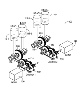
communication interface 918 is
to send and receive a variety of signals (e.g., electrical, optical, or other
signals) that transmit
17
CA 03223410 2023- 12- 19
WO 2023/004121
PCT/US2022/038026
data streams representing various data types. The intelligent power controller
118 may also
include one or more input/output devices 916 that enable user interaction with
the intelligent
power controller 118 (e.g., camera, display, keyboard, mouse, speakers,
microphone, buttons,
etc.). The input/output devices 916 may include peripherals, such as a camera,
printer, scanner,
display screen, etc. For example, the input/output devices 916 may include a
display device
such as a cathode ray tube (CRT), plasma or liquid crystal display (LCD)
monitor for
displaying information to the user, a keyboard, and a pointing device such as
a mouse or a
trackball by which the user can provide input to the intelligent power
controller 118, and the
intelligent power controller 118 may be any one of a variety of hardware
devices. For
example, a network-enabled portable tablet computer and/or dedicated portable
hardware
device, configured in accordance with FIGS. 4 and 5, may be employed in the
context of the
disclosed embodiments.
100491 As noted above, the intelligent power controller 118 is
communicatively
coupled to the electrical load 116 and to the plurality of power management
devices for
selectively controlling power monitoring, power generation, power distribution
and power
storage between or to the plurality of battery banks (i.e., battery bank 1102,
battery bank 2 104
and battery bank 3 106), the at least one electrical load 116 and the
plurality of HEADs (i.e.,
HEAD 116-1, HEAD 116-2, HEAD 116-3, and HEAD 116-4). In accordance with an
embodiment, the delivery of the aforementioned operations is facilitated by
the execution of the
multi-hybrid power generator application 500, and FIG. 6 shows an illustrative
architecture for
the multi-hybrid power generation application 500 for use with the multi-power
generator
system 100. As shown, the illustrative architecture for the operation of the
application 500
provides several modules and engines used to perform a variety of functions
for energy
harvesting, generation and storage from interchangeable power sources and for
selectively
controlling the power monitoring, power generation, power distribution and
power storage
features across the multi-hybrid power generator system 100 and, in
particular, by controlling
the plurality of HEADs (i.e., READ 116-1, READ 116-2, HEAD 116-3, and READ 116-
4)
which, in turn, work to control the various parts of the multi-hybrid power
generator system
100, as further detailed herein. In conjunction with the operation of
execution engine 502, the
monitoring and controlling of the plurality of HEADs is undertaken by power
monitoring
module 504, power generation module 506, power distribution module 508, HEAD
module 520
18
CA 03223410 2023- 12- 19
WO 2023/004121
PCT/US2022/038026
and power management module 514. Further, the artificial intelligence (AI)
module 510 may
be used to define and execute an AT protocol, through AT processor 920, to
enhance the
operations of the multi-hybrid power generator system 100 by, for example,
collecting and
interpreting data provided by the plurality of power management units to
generate various
responses and actions to be taken by the plurality of power management units,
with respect to
power monitoring, thereby increasing the overall efficiency of the multi-
hybrid power
generator system 100.
[0050] The communications and data collection module 512
facilitates communications
and data collection between and from the intelligent power controller 118 and
the plurality of
HEADs (i.e., HEAD 116-1, READ 116-2, HEAD 116-3, and HEAD 116-4). In this way,
the
power distribution module 508 can route and distribute power throughout the
multi-hybrid
power generator system 100, as detailed herein. The power management module
514 provides
overall power management with respect to the generated power from the multi-
hybrid power
generator system 100 including power distribution to the at least one
electrical load 116 and the
plurality of battery banks (i.e., battery bank 1102, battery bank 2 104 and
battery bank 3 106).
The power storage module 518 controls the storage of such generated power
across, for
example, the plurality of battery banks (i.e., battery bank 1102, battery bank
2 104 and battery
bank 3 106). The power management module 514 also provides for operations that
control and
prevent overloading and overheating conditions across the various components
of the multi-
hybrid power generator system 100 by measuring and monitoring overall system
capacity and
generated power flow and directing electrical power to one or more of the
plurality of batteries
and/or the at least one electrical load 116. The data display interface 516
module and the
communication and data collection module 512 are used to facilitate the
input/output and
display of power data and other information illustratively (e.g., a graphical
user interface) to the
users across the multi-hybrid power generator system 100.
[0051] Referring to FIG. 7, an illustrative power management
device 600 is configured
for use in the multi-hybrid power generator system of FIG. 1 in accordance
with an
embodiment multi-hybrid power generator system 100. The illustrative power
management
device 600 configuration is applicable to any of the plurality of power
management devices
(i.e., SIR 114-1 through SIR 114-5) as shown in FIG. 1. As shown in FIG. 6,
each power
management unit includes at least one sensor unit 616 for measuring power at
any given time,
19
CA 03223410 2023- 12- 19
WO 2023/004121
PCT/US2022/038026
at least one inverter unit 614 for changing direct current (DC) to alternating
current (AC), and
at least one energy router unit 612 for managing power distribution.
Communications interface
620 manages communications such that each power management unit is
communicatively
coupled with and to the intelligent power controller 118 for selectively
controlling power
monitoring, power generation, power distribution and power storage between or
to the plurality
of battery banks (i.e., battery bank 1102, battery bank 2 104 and battery bank
3 106), the at
least one electrical load 116, and the plurality of HEADs (i.e., HEAD 116-1,
HEAD 116-2,
HEAD 116-3, and HEAD 116-4). The power management device 600 is powered by
power
source 622 and further includes bus 618 and processor 602 coupled to the bus
618 for
executing operations and processing information by the execution of HEAD app
610 as stored
in data storage 608. The power management device 600 may also include ROM 606
or
other static storage device(s) coupled to the bus 618. The main memory 604 may
each include
a tangible non-transitory computer readable storage medium or other memory
devices, as
detailed herein above, for storing executable code and/or other information
useful in the
execution the HEAD app 610.
100521 Referring to FIG. 8, a flowchart of illustrative
operations 700 is shown for
harvesting energy from an interchangeable power source using the multi-hybrid
power
generator system of FIG. 1, in accordance with an embodiment of the invention.
As shown, the
operations 700 include, at step 702, collecting energy from an interchangeable
power source
such as, for example, the array of photovoltaic (PV) solar panels (i.e., PV
solar panel 110-1, PV
solar panel 110-2, PV solar panel 110-3 and PV solar panel 110-4), and, at
step 704, storing the
energy collected in a first battery bank 102 of a plurality of battery banks.
Then, at step 706, in
accordance with a series of power harvesting stages, converting the
interchangeable power
source energy collected and stored in the first battery bank 102 into
electrical energy using a
plurality of power management devices and a multi-hybrid power generator
including a
plurality of HEADs. As indicated above, each power management device includes
at least one
sensor for measuring power at any given time, at least one inverter for
changing direct current
(DC) to alternative current (AC), and at least one energy router for managing
power
distribution.
100531 The method 700 further includes, at step 708, driving,
under control of at least a
second power management device 114-2 in accordance with a first stage of the
series of power
CA 03223410 2023- 12- 19
WO 2023/004121
PCT/US2022/038026
harvesting stages, a first generator 136, mechanically connected to a first
gearbox 132
including a first set of gears 134, for generating and supplying electrical
energy to a second
battery bank 104 of the plurality of power banks by driving a first HEAD 116-1
of the plurality
of HEADs that drives a first piston 120-1 of the plurality of pistons having a
first pair of
retracting springs 128 connected thereto. The first piston 120-1 is located
within a first
hydraulic chamber 130-1 and is mechanically connected to a first piston rod
122-1 of the
plurality of piston rods to drive a second HEAD 116-2 of the plurality of
HEADs and a second
piston 120-2 of the plurality of pistons having a second pair of retracting
springs connected
thereto. The second piston 120-2 is located within a second hydraulic chamber
130-2 and is
mechanically connected a second piston rod 122-2 of the plurality of piston
rods. The first
piston rod 122-1 and the second piston rod 122-2 are mechanically connected to
a first
crankshaft 124 including a first driving gear 206, a first counterweight 202,
and a second
counterweight 204 connected thereto. The first driving gear 206 is located at
a first center
point along the first crankshaft 124 and is mechanically connected to the
first set of gears 134
of the first gear box 132 for driving the first set of gears 134 of the first
gearbox 132. The first
HEAD 116-1 and the second HEAD 116-2 drive the first piston 120-1 and piston
rod 122-1 and
the second piston 120-2 and piston rod 122-2, respectively, that in turn drive
the first crankshaft
124 and the first driving gear 206, which is mechanically connected thereto
such that the first
driving gear 206 drives the first set of gears 134 of the first gearbox 132
for powering the first
generator 136. The first generator 136 is electrically connected to and
supplies electrical power
to a second battery bank 104 of the plurality of battery banks. The first
generator 136 and the
second battery bank 104 are electrically connected to a third power management
unit 114-3 of
the plurality of power management units.
[0054] A step 710, driving, under control of the second power
management device 114-
2 in accordance with a second stage of the series of power harvesting stages,
a second generator
142 mechanically connected to a second gearbox 138 including a second set of
gears 140,
generates and supplies electrical energy to a third battery bank 106 of the
plurality of power
banks by driving a third HEAD 120-3 of the plurality of HEADs, which drives a
third piston
120-3 of the plurality of pistons having a third pair of retracting springs
128 connected thereto.
The third piston 120-3 is located within a third hydraulic chamber 130-3 and
is mechanically
connected to a third piston rod 122-3 of the plurality of piston rods, and
drives a fourth HEAD
21
CA 03223410 2023- 12- 19
WO 2023/004121
PCT/US2022/038026
116-4 of the plurality of HEADs and a fourth piston 120-4 of the plurality of
pistons having a
fourth pair of retracting springs 128 connected thereto. The fourth piston 120-
4 is located
within a fourth hydraulic chamber 130-4 and is mechanically connected to a
fourth piston rod
122-4 of the plurality of piston rods. The third piston rod 122-3 and the
fourth piston rod 122-4
arc mechanically connected to a second crankshaft 126 including a second
driving gear 206, a
third counterweight, and a fourth counterweight connected thereto. The second
driving gear
206 is located at a second center point along the second crankshaft 126 and is
mechanically
connected to the second set of gears 140 of the second gear box 138 for
driving the second set
of gears 140 of the second gearbox 138. The third HEAD 116-3 and the fourth
HEAD 116-4
drive the third piston 120-3 and piston rod 122-3 and the fourth piston 120-4
and piston rod
122-4, respectively, driving the second crankshaft 126 and the second driving
gear 206
mechanically connected thereto such that the second driving gear 206 drives
the second set of
gears 140 of the second gearbox 138 for powering the second generator 142. The
second
generator 142 is electrically connected to and supplies electrical power to a
third battery bank
106 of the plurality of battery banks. As illustrated in FIG. 1 and as
discussed hereinbefore, the
second generator 142 and the third battery bank 106 are electrically connected
to a fourth
power management unit 114-4 of the plurality of power management units. The
first
crankshaft 124 and the second crankshaft 126 are joined by a weighted
separator support joint
208 mechanically connected such that the weighted separator support joint 208
separates the
first crankshaft 124 and the second crankshaft 126 to allow for independent
operation of one
from the other.
[0055] At step 712, the method further includes selectively
controlling, using an
intelligent power controller 118 communicatively coupled to at least one
electrical load 116
and to the plurality of power management devices, a distribution of the
electrical energy
generated and supplied by the first generator 136 and the second generator
142, respectively,
between or to the at least one electrical load, the plurality of battery
banks, and the plurality of
HEADs.
[0056] In this way, the operations allow for the harvesting,
generation, storage, and
management of power from an interchangeable power source for distribution in
energizing an
electrical load and for storing in a plurality of battery banks. Specifically,
the intelligent power
controller 118 operates the battery bank(s) 102, 104, 106 and HEADs 116 in
stages to provide
22
CA 03223410 2023- 12- 19
WO 2023/004121
PCT/US2022/038026
cooling cycles for at least one battery bank and/or at least one READ during
operation of the
remaining battery bank(s) and/or READ(s), as depicted in FIG. 8. For example,
during the first
stage 708, the intelligent power controller 118 controls a first subset of the
HEADs (e.g.,
HEADs 116-1 and 116-2) to power the first generator 136. During a second stage
710, the
intelligent power controller 118 controls a second subset of the HEADs (e.g.,
HEADs 116-3
and 116-4) to power a second generator 142. During a third stage, the
intelligent power
controller 118 controls both subsets of HEADs (e.g., HEADs 116-1, 116-2, 116-3
and 116-4) in
unison to drive the first generator 136 and the second generator 142. During a
fourth stage, the
intelligent power controller 118 alternates from the first stage to the second
stage (alternating
between the first subset of HEADs and the second subset of HEADs), from the
first stage to the
third stage (from the first subset of HEADs to all of the HEADs), and/or from
the second stage
to the third stage (from the second subset of HEADs to all of the HEADs) to
provide efficient
energy generation and keep a portion of the multi-hybrid power generator
system in a cooling
cycle mode. The fourth stage allows a portion of the multi-hybrid power
generator system 100
to cool itself off as an alternate portion of the multi-hybrid power generator
system 100 works
by having a portion of the power generator system 100 to experience
intermittent downtime.
That is, operating the HEADs in cycles, the non-operational periods provide
downtime which
allows for cooling of such components, increasing the overall operational
efficiency of the
system. During the third stage and the fourth stage the multi-hybrid power
generator system
100 delivers power on demand and/or to a battery 102, 104, 106. The ability to
charge batteries
and supply power to an on-demand/active load makes the system 100 efficient
enough to
perform either in the day or night, with or without solar energy input for a
significant amount
of time. The system 100 operates with significantly reduced input power during
the fourth
stage, allowing efficient power generation, storage, and distribution. The
intelligent power
controller 118 distributes power via on and off cycles based on power storage
and power usage
capacity and needs.
[0057] In some embodiments, the multi-hybrid power generator
system 100 operates
the first set of gears 134 and the second set of gears 140 synchronously,
independently, and/or
alternatively. This significantly increases the efficiency, efficacy and
durability of the system
100 by avoiding continuous mechanical motion without a resting period like
traditional
generators.
23
CA 03223410 2023- 12- 19
WO 2023/004121
PCT/US2022/038026
100581 In an embodiment, each retracting spring 128 is made of a
spring material, as
hereinbefore disclosed, and is balanced at an operating angle to increase the
effect of the piston
120 on the crankshaft 200. The HEADs 116 are supported by the retracting
spring 128 and the
retracting spring 128 is disposed inside of the piston 120. In one embodiment,
the operating
angle is approximately 25 degrees (i.e., angled inward with respect to a
piston axis, moving
from top to bottom). In an embodiment, the operating angle is preferably
between 24.618 and
26.973 degrees. The spring material and balancing of the retracting spring 128
increases both
the efficiency and the life expectancy of the piston 120. The configuration of
the springs 128,
and the location of the springs 128 within the pistons 120 or piston chamber
130 increases the
efficiency, efficacy, and longevity of the HEAD 116, as well as the system, as
a whole. The
springs 128 support the upward/downward motion during the retraction and
discharging of the
HEAD-to-piston cycle and the piston-to-HEAD cycle to and from the original
start position.
100591 Importantly, harvested power stored in the first battery
bank 102 is utilized to
supply the appropriate initial power to the HEADs. The second battery bank 104
and third
battery bank 106 can also be utilized to supply power to the both the HEADs
and to the load
(e.g., load 116) simultaneously as necessary, and can switch back and forth
depending on what
part of the battery system is calling for it to be charged, and as the
controller 118 determines is
most optimum to maintain the efficiency of the entire power generation system.
100601 As will be appreciated, during operation of the HEADs,
the components of the
HEADs increase in temperature due, at least partially, due to friction of the
moving parts.
When a temperature of a first HEAD set, for example, exceeds a threshold
temperature, the
controller 118 effects a switch from the first HEAD set to another HEAD set
(e.g., a second
HEAD set). This deactivation of the first HEAD set allows for the first HEAD
set to be cooled
until it reaches an optimal operating temperature. Importantly, however, the
HEAD system can
be operated continuously, alternating between the first HEAD set and the
second HEAD set to
provide downtime cycles for each HEAD set while the second HEAD set maintains
system
operation. The cooling ability of the HEADs/HEAD sets allow the stored power
(potential) of
the HEADs/HEAD sets (hydraulic/electrical systems) to never overheat due to
this
interchanging/interoperability function.
100611 Importantly, as disclosed above, the HEADs/HEAD sets work
together similar
to the balance of bicycle peddles on a bicycle with the upward/downward
motion. The
24
CA 03223410 2023- 12- 19
WO 2023/004121
PCT/US2022/038026
HEADs/HEAD sets drive mechanical energy via the pistons then to the piston
rods toward the
crankshaft. The upstroke/downstroke forces created by the HEADs/HEAD sets are
supported
by the specifically designed springs 128 located inside the pistons for
maximum and optimum
efficiency, efficacy and longevity. These springs support the upward/downward
motion during
the retracting/discharging of the HEAD-to-piston cycle (discharge) and piston-
to-HEAD cycle
(retraction) to and from its original start position.
[0062] As disclosed above, an important aspect of the system 100
is the ability for the
HEADs/HEAD sets to operate as optimum and efficient as possible via on/off
cycle
arrangements (cooling cycles) in stages, including a first stage where a first
subset of HEADs
(e.g. first and second HEADs 116-1, 116-2) are used to power the first set of
gears to power the
first power generator 136, a second stage where a second subset of HEADs
(e.g., second and
third heads 116-3, 116-4) are used to power the second set of gears to power
the second power
generator 142, a third stage where the first and second subset of HEADs are
operated in unison
(synchronously) to drive the mechanical power to both gearboxes to drive both
generators 136,
142, and a fourth stage whereby the SIR units work with the intelligent power
controller 118 to
alternate the stages from the first stage to the second state, from the first
stage to the third stage,
and/or the second stage to the third stage to work efficiently while keeping
the other portions of
the system 100 in a cooling cycle mode (off cycle). The combination of the
HEAD, retracting
spring, counterweight and gear system, along with the controlled operation in
stages, provides
an improved efficiency performance ranging between 76% to 85%.
[0063] The fourth stage provides for the increased mechanical
efficiency of the system
by allowing the system to "cool" itself When portions of the system are
operating in the "off
cycle" mode, this allows this part of the system to rest, and the part of the
system that is
working "on cycle" can continue to run efficiently to avoid any potential
overheating.
[0064] One particular benefit provided by the third stage is the
ability of the power
generation system 100 to deliver necessary power on demand and/or supply power
to batteries
for later usage synchronously or alternatively. Due to the electromechanical
arrangement of
the fourth stage, the power generation and storage efficiency is greatly
increased, whereas the
demand for the input power (PV panels) decreases. Moreover, operation in the
fourth stage or
mode of operation, in conjunction the SIR units, allows the power generated to
supply the load
and charge different battery banks at the same time simultaneously. Due to
this effect, the
CA 03223410 2023- 12- 19
WO 2023/004121
PCT/US2022/038026
system operates with reduced input power (lower amount of PV panels).
Moreover, the ability
to charge batteries and supply power to an on-demand/active load 116 renders
the present
system efficient to the point it can perform either in the day or night with
or without solar
energy input for a significant amount of time before requiring the solar input
(power initiation).
[0065] In connection with the above, the SIR units 114-1, 114-2,
114-3, 114-4 in
between the three battery banks 102, 104, 106 serves as a monitoring sensor
and router that
measures the battery banks' ability to store additional power and/or route the
power for
consumption or storage. Another major function of the SIR unit between battery
banks is to
allow the alternating battery bank to accept power to charge its respective
bank with its unit
power generator or the other unit generator thereby increasing total system
efficiency. The SIR
units also serve as the main signal detection point of incoming power
generation and routing of
said power throughout the entire power generation system.
[0066] In further embodiments, there may be an initial powering,
using the
interchangeable power source energy stored in the first battery bank of the
plurality of battery
banks, in accordance the first stage and the second stage of the series of
power harvesting
stages, as detailed above. Further, there may be an additional step of
distributing, under control
of the intelligent power controller, the electrical energy generated and
supplied by the first
generator and the second generator, respectively, for storing in the second
battery bank and the
third battery bank and energizing the at least one electrical load. In
addition, there may be a
step 714 of driving, in a third stage of the series of power harvesting
stages, mechanical power
to the first crankshaft and the second crankshaft, the first stage and the
second stage of the
power harvesting stages are operating synchronously during the third stage of
the series of
power harvesting stages. Further, there may be a step 716 of alternating, in a
fourth stage of
the series of power harvesting stages, between any two of the four power
harvesting stages.
Alternating between cycles having three (3) battery banks specifically allows
the system 100 to
operate smoothly and to allow cooling cycles without impeding operation of the
system 100.
[0067] In some embodiments the method or methods described above
may be executed
or carried out by a computing system including a tangible computer-readable
storage medium,
also described herein as a storage machine, that holds machine-readable
instructions
executable by a logic machine (i.e., a processor or programmable control
device) to provide,
implement, perform, and/or enact the above-described methods, processes,
and/or tasks. When
26
CA 03223410 2023- 12- 19
WO 2023/004121
PCT/US2022/038026
such methods and processes are implemented, the state of the storage machine
may be changed
to hold different data. For example, the storage machine may include memory
devices such as
various hard disk drives, CD, or DVD devices. The logic machine may execute
machine-
readable instructions via one or more physical information and/or logic
processing devices.
For example, the logic machine may be configured to execute instructions to
perform tasks for
a computer program. The logic machine may include one or more processors to
execute the
machine-readable instructions. The computing system may include a display
subsystem to
display a graphical user interface (GUI), or any visual element of the methods
or processes
described above. For example, the display subsystem, storage machine, and
logic machine
may be integrated such that the above method may be executed while visual
elements of the
disclosed system and/or method are displayed on a display screen for user
consumption. The
computing system may include an input subsystem that receives user input. The
input
subsystem may be configured to connect to and receive input from devices such
as a mouse,
keyboard, or gaming controller. For example, a user input may indicate a
request that certain
task is to be executed by the computing system, such as requesting the
computing system to
display any of the above-described information or requesting that the user
input updates or
modifies existing stored information for processing. A communication subsystem
may allow
the methods described above to be executed or provided over a computer
network. For
example, the communication subsystem may be configured to enable the computing
system to
communicate with a plurality of personal computing devices. The communication
subsystem
may include wired and/or wireless communication devices to facilitate
networked
communication. The described methods or processes may be executed, provided,
or
implemented for a user or one or more computing devices via a computer-program
product
such as via an application programming interface (API).
[0068]
Since many modifications, variations, and changes in detail can be made
to the
described preferred embodiments of the invention, it is intended that all
matters in the
foregoing description and shown in the accompanying drawings be interpreted as
illustrative
and not in a limiting sense. Thus, the scope of the invention should be
determined by the
appended claims and their legal equivalents.
27
CA 03223410 2023- 12- 19