Note: Descriptions are shown in the official language in which they were submitted.
IMMERSION NOZZLE
Technical Field
[0001] The present invention relates to an immersion nozzle to be used to
continuously cast thin
slabs.
Background Art
[0002] Attention has been directed to omission of a slab heating process and
energy-saving
effects achieved by so-called direct coupling, i.e. directly coupling
continuous casting and hot
rolling of a resulting slab. To realize this, thinner slabs on the continuous
casting side are being
sought. When casting a thin slab (e.g. with a thickness of 200 mm or less), a
mold needs to be
flattened, and necessarily an immersion nozzle also needs to be flattened
(e.g. Patent Document
1).
Prior Art Documents
Patent Documents
[0003] Patent Document 1: JP H08-039208A
Summary of Invention
Technical Problem
[0004] Especially, skinning is often problematic in thin-slab casting. This is
because the surface
temperature of thin slabs is more likely to drop than that of ordinary slabs
due to the large
slenderness ratio of the area of a molten steel surface, and the larger the
nozzle cross-sectional
area of an immersion section is, the more likely the temperature drops due to
heat removal using
the nozzle.
[0005] According to the immersion nozzle described in Patent Document 1, it is
possible to
prevent sticking of base metal that occurs between the immersion nozzle and a
mold wall and
skinning on a molten metal surface that occurs near the short sides of a wide
mold, as well as the
occurrence of a molten metal suction phenomenon, remelting of a solidifying
shell, and the like.
However, it cannot be said that the immersion nozzle described in Patent
Document 1 sufficiently
suppresses skinning in a meniscus part.
[0006] There is demand for realization of an immersion nozzle capable of
suppressing skinning
in a meniscus part in thin-slab continuous casting.
1
CA 03223418 2023- 12- 19
Solution to Problem
[0007] An immersion nozzle according to the present invention is an immersion
nozzle having
a flow channel and openings; the immersion nozzle comprising: a first section;
a connection
section; and a second section, the first section, the connection section, and
the second section
being provided in this order from a base end side, wherein the flow channel in
the first section
has a lateral cross-sectional shape that is a circular shape, the flow channel
in the second section
has a lateral cross-sectional shape that is a rectangular shape, the flow
channel in the connection
section has a shape with which the flow channel in the first section is
continuously connected to
the flow channel in the second section, the rectangular shape of the second
section has long sides
each having a length a and short sides each having a length b, with a ratio
a/b between the length
a and the length b being 3 or greater and 7 or less, the flow channel in the
second section has a
cross-sectional area S2, the flow channel in the first section has a cross-
sectional area Si, and the
cross-sectional area S2 is larger than the cross-sectional area Si, the
openings include two first
openings and two second openings, the first openings are open, in one-to-one
correspondence, in
two side faces of the second section that correspond to the two short sides,
one of the two second
openings is open while extending from one of the two side faces to a bottom
face of the second
section, the bottom face being a face at a leading end of the second section,
and another one of
the two second openings is open while extending from another one of the two
side faces to the
bottom face.
[0008] Using the immersion nozzle having the above configuration in thin-slab
continuous
casting can suppress skinning in the meniscus part.
[0009] Preferred examples of the present invention will be described in detail
below. Note that
the following preferred examples are not intended to limit the scope of the
present invention.
[0010] In the immersion nozzle according to the present invention, it is
preferable as one aspect
that each of the first openings has an opening area S3 in a corresponding one
of the side faces,
each of the second openings has an opening area S4 in a corresponding one of
the side faces and
an opening area S5 in the bottom face, and the opening areas S3, S4, and S5
satisfy expressions (1)
and (2) below:
S4 < S5 (1)
(S4 + S5) / S3 1.5 (2)
[0011] A discharge flow discharged from the nozzle hits a short side of the
mold and separates
into an upward flow and a downward flow. Here, if the upward flow is
excessively strong, powder
entrainment or the like is likely to occur, while if the downward flow is
excessively strong,
2
CA 03223418 2023- 12- 19
inclusions, bubbles, or the like is unlikely to rise to the surface. According
to the above
configuration, the balance between the upward flow and the downward flow is
optimized, and an
excessive meniscus flow can be suppressed.
[0012] In the immersion nozzle according to the present invention, it is
preferable as one aspect
that each of the first openings has an opening area S3 in a corresponding one
of the side faces and
an opening area S6 on a flow channel side, and the opening area S3 is smaller
than the opening
area S6.
[0013] According to this configuration, the occurrence of a suction flow in
the first opening can
be suppressed.
[0014] In the immersion nozzle according to the present invention, it is
preferable as one aspect
that the immersion nozzle has a largest width of 300 mm or less.
[0015] According to this configuration, workability is improved when
implementing work to
replace the immersion nozzle using a quick changer. This enables the nozzle to
be quickly
changed during casting, which can meet the increasing need to cast high-grade
steel types that
involve strict casting conditions in thin-slab continuous casting.
[0016] Further features and advantages of the present invention will become
clearer with the
description of the following illustrative and non-limiting embodiments, which
are described with
reference to the drawings.
Brief Description of Drawings
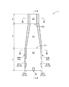
[0017] FIG. 1 is a front cross-sectional view of a nozzle according to an
embodiment.
FIG. 2 is a side cross-sectional view (cross-sectional view taken along a line
II-II in FIG.
1) of the nozzle according to the embodiment.
FIG. 3 is a lateral cross-sectional view (cross-sectional view taken along a
line III-III in
FIG. 1) of a first section of the nozzle according to the embodiment.
FIG. 4 is a lateral cross-sectional view (cross-sectional view taken along a
line IV-IV in
FIG. 1) of a second section of the nozzle according to the embodiment.
FIG. 5 is a side view of the second section of the nozzle according to the
embodiment.
FIG. 6 is a bottom view of the second section of the nozzle according to the
embodiment.
Description of Embodiments
[0018] An embodiment of the immersion nozzle according to the present
invention will be
described with reference to the drawings. The following is a description of an
example where the
immersion nozzle according to the present invention is applied to an immersion
nozzle 1
3
CA 03223418 2023- 12- 19
(hereinafter referred to simply as a "nozzle 1"), which is used to slab
continuous casting with a
mold thickness of 200 mm or less.
[0019] Overall configuration of immersion nozzle
The nozzle 1 is a tubular member made of a refractory material. A flow channel
for
allowing molten steel to flow is formed inside the nozzle 1, which has
openings 5 at a leading
end. The nozzle 1 has a first section 2, a connection section 3, and a second
section 4 in this order
from a base end side, and these sections have different shapes (FIGS. 1 and
2). The nozzle 1 is
joined to upstream equipment (such as a stopper or a sliding nozzle; not
shown) at the first section
2, and molten steel flowing from the upstream equipment flows through the flow
channel. The
second section 4 includes the openings 5 (first openings 51 and second
openings 52), from which
the molten steel flows out to a mold (not shown).
[0020] The type of refractory material that constitutes the nozzle 1 is not
specifically limited,
and may be any refractory material conventionally used in this field. Examples
of such refractory
materials include alumina-graphite, magnesia-graphite, spinel-graphite,
zirconia-graphite,
calcium zirconate-graphite, high-alumina, alumina-silica, silica, zircon, and
spinel. Zone lining
may also be applied as appropriate.
[0021] The following description mentions directions based on the orientation
shown in FIG. 1.
That is, when mentioning the up-down direction, "up" (including upper part,
above, upper side,
upstream etc.) refers to the base end side (first section 2 side), and "down"
(including lower part,
below, lower side, downstream etc.) refers to the leading end side (second
section 4 side).
[0022] Also, when mentioning a cross section of the flow channel, it refers to
a cross section in
a direction orthogonal to the above-defined up-down direction (a direction
orthogonal to the paper
plane of FIG. 1), and this cross section is referred to as a lateral cross
section, unless otherwise
stated. Note that when the nozzle 1 is used, molten steel flows from the above-
defined upper side
toward the above-defined lower side. Thus, the above-defined lateral cross
section is also a cross
section relative to the flow direction of the molten steel.
[0023] Configuration of first section
The first section 2 is a main section on the base end side of the nozzle 1.
The lateral cross
section of a flow channel 21 in the first section 2 has a circular shape
(FIGS. 1 to 3). Note that
the circular shape as used herein is not limited to a circular shape in the
mathematical sense, and
may be a shape that can be dealt with as a substantially circular shape.
Accordingly, a deviation
(tolerance etc.) from a mathematically circular shape that may occur in an
attempt to realize a
circular shape as an industrial product is acceptable. A cross-sectional area
Si of the flow channel
21 in this embodiment is 6000 mm2.
4
CA 03223418 2023- 12- 19
[0024] Configuration of second section
The second section 4 is a main section on the leading end side of the nozzle
1. The lateral
cross section of a flow channel 41 in the second section 4 has a rectangular
shape (FIGS. 1, 2 and
4). Note that the rectangular shape as used herein is not limited to a
rectangular shape in the
mathematical sense, and may be a shape that can be dealt with as a
substantially rectangular shape.
Accordingly, deformation (chamfering etc.) that is ordinarily applied in an
attempt of realizing a
rectangular shape as an industrial product may be imparted, and a deviation
(tolerance etc.) from
a mathematically rectangular shape is acceptable.
[0025] A cross-sectional area S2 of the flow channel 41 in this embodiment is
10000 nun2.
Accordingly, the cross-sectional area S2 of the flow channel 41 is greater
than the cross-sectional
area Si of the flow channel 21. The flow velocity of molten steel discharged
from the openings 5
is reduced by thus making the cross-sectional area in the downstream area
(flow channel 41)
larger than the cross-sectional area in the upstream area (flow channel 21).
This causes an upward
flow in the mold and suppresses an excessive meniscus flow.
[0026] In the lateral cross-sectional shape of the flow channel 41 in this
embodiment, the
rectangle has long sides 42 each having a length a of 200 mm, and short sides
43 each having a
length b of 50 mm (FIG. 4). Thus, the ratio a/b between the lengths a and b is
4Ø Note that
numerical values of the rectangular shape are not limited to the above values
and may be changed
in the range of the ratio a/b from 3 to 7. If the ratio a/b is changed, both
the length a of the long
sides 42 and the length of the short sides 43 of the rectangular shape may be
changed. Meanwhile,
the length b of the short sides 43 is restricted by the length of the short
sides of the mold, and the
length a of the long sides 42 is, therefore, more flexible in general.
[0027] The ratio a/b being in the range from 3 to 7 makes a molten steel flow
unlikely to detach
from the wall face of the flow channel 41 and allows for an appropriate flow.
In contrast, the ratio
a/b being less than 3 makes the length a of the long sides 42 excessively
small and makes it
difficult to secure an inner tube cross-sectional area necessary for casting.
Further, the ratio a/b
being greater than 7 makes the length a of the long sides 42 excessively large
and makes the
weight of the nozzle 1 more likely to increase, which may increase the load of
a worker or a
device that handles the nozzle 1. In addition, the ratio a/b being greater
than 7 may cause the flow
channel 31 to be steeply deformed in the longitudinal direction of the
connection section 3 and
may detach the molten steel flow from the wall face of the flow channel.
[0028] The lateral cross-sectional shape of the substantial part (refractory
material part) of the
second section 4 also has a rectangular shape in correspondence with the
rectangular shape of the
lateral cross section of the flow channel 41. Thus, the second section 4 has a
bottomed rectangular
5
CA 03223418 2023- 12- 19
column shape. A face of the rectangular shape that corresponds to each long
side 42 has a width
W of 270 mm, which is the largest width of the nozzle 1. The largest width W
of the nozzle 1 thus
being less than 300 mm improves workability when implementing work to replace
the nozzle 1
using a quick changer, which is favorable. This is because the largest width W
of the nozzle 1
being less than 300 mm makes it easier to secure room for the work to replace
the nozzle 1 within
the mold due to the dimensional relationship between the nozzle 1 and the
mold.
[0029] Configuration of opening
The first openings 51 are open in side faces 44 of the second section 4 that
correspond
to the short sides 43 of the rectangular shape (FIGS. 1 and 5). Two first
openings 51 are provided.
The two first openings 51 (51A and 51B) are open in two side faces 44 (44A and
44B)
corresponding to two short sides 43 (43A and 43B) in one-to-one
correspondence. The first
openings 51 being open in the side faces 44 allow the molten steel flow to be
discharged toward
the short sides of the mold. This can cause an upward flow in the mold and
promote heat supply
to a meniscus.
[0030] Also, two second openings 52 are open while extending between the side
faces 44 and
a bottom face 45, which is a face of the second section 4 at the leading end
in the longitudinal
direction (FIGS. 1, 5 and 6). Of the two second openings 52, one second
opening 52A is open
while extending between the side face 44A (one side face) and the bottom face
45, and the other
second opening 52B is open while extending between the side face 44B (the
other side face) and
the bottom face 45. The second openings 52 being open in the above mode allow
the molten steel
flow to be discharged to the lower side of the mold and enable appropriate
distribution of the
molten steel flow in the mold.
[0031] In this embodiment, an opening area S3 of each first opening 51 in the
corresponding
side face 44 (the area of the first opening 51 shown in FIG. 5) is 2700 mm2.
An opening area S4
of each second opening 52 in the corresponding side face 44 (the area of the
second opening 52
shown in FIG. 5) is 2000 mm2, and an opening area S5 thereof in the bottom
face 45 (the area of
the second opening 52 shown in FIG. 6) is 5000 mm2. Based on the above opening
areas, the
following expressions (1) and (2) hold.
S4 < S5 (1)
(S4 + S5) / S3 > 1.5 (2)
[0032] The first openings 51 and the second openings 52 having the opening
areas that satisfy
the expressions (1) and (2) can optimize the balance between the upward flow
and the downward
flow and suppress an excessive meniscus flow. Note that the opening area S3 of
the first openings
51 and the opening areas S4 and S5 of the second openings 52 are not limited
to the above values
6
CA 03223418 2023- 12- 19
and may be changed as long as the expressions (1) and (2) are satisfied.
[0033] In this embodiment, an opening area S6 of each first opening 51 on the
flow channel 41
side is 4000 mm2. Accordingly, the opening area S3 of each first opening 51 in
the side face 44 is
smaller than the opening area S6 on the flow channel 41 side.
[0034] Adopting a configuration in which the opening area S6 of each first
opening 51 on the
flow channel 41 side is greater than or equal to the opening area S3 thereof
in the side face 44
gradually decreases the cross-sectional area of the flow channel toward
outlets of the molten steel
flow in the flow direction, and thus rectifies the molten steel flow. This
suppresses the occurrence
of a suction flow in an upper part of the first opening 51 and makes it easier
for the molten steel
to be smoothly discharged from the entire first openings 51.
[0035] Configuration of connection section
The connection section 3 is a section that continuously connects the first
section 2 to the
second section 4 (FIGS. 1 and 2). The connection section 3 includes a flow
channel 31 having a
shape that continuously connects the flow channel 21 in the first section 2
having a circular cross-
sectional shape to the flow channel 41 in the second section 4 having a
rectangular cross-sectional
shape. The cross-sectional shape of the flow channel 31 is, therefore,
circular at an upper end 32
and rectangular at a lower end 33.
[0036] Other Embodiments
Lastly, other embodiments of the immersion nozzle according to the present
invention
are described. Note that the configuration disclosed in the following
embodiments can also be
applied in combination with configurations disclosed in other embodiments as
long as no
contradiction arises.
[0037] In the above embodiment, a description has been given of an example of
a configuration
in which the opening areas S3, S4, S5, and S6 of the openings 5 (first
openings 51 and second
openings 52) satisfy the expressions (1) and (2), and S3 is smaller than S6.
However, the
immersion nozzle according to the present invention need not satisfy at least
either the
expressions (1) or (2), and S3 may be greater than S6.
[0038] In the above embodiment, a description has been given of an example of
a configuration
in which the largest width W of the nozzle 1 is 270 mm, which is less than 300
mm. However,
the largest width of the immersion nozzle according to the present invention
may be 300 mm or
greater.
[0039] Regarding other configurations as well, it should be understood that
the embodiments
disclosed herein are in all respects illustrative and the scope of the present
invention is not limited
thereby. Those skilled in the art would readily understand that modifications
can be made as
7
CA 03223418 2023- 12- 19
appropriate without departing from the gist of the present invention.
Therefore, other
embodiments modified without departing from the gist of the present invention
are naturally
encompassed in the scope of the present invention.
Examples
[0040] The present invention will be further described below by describing
examples. However,
the present invention is not limited by the following example.
[0041] Test method
Nozzles with various dimensional conditions were designed, and numerical fluid
dynamics calculations were performed for modes of discharged molten steel flow
using fluid
analysis software PHOENICS produced by CHAM-japan. The dimensional conditions
for
examples and comparative examples are as listed in Tables 1 below. Flow
velocity contour plots
were output based on the calculation results. Note that the following
parameters were applied in
the calculations.
- Number of calculation cells: Approximately 500,000 (which may vary depending
on
the model)
- Fluid: Molten steel (1560 C, density: 7.08 g/cm3)
- Casting speed: 4 tons per minute
- Mold size: 1200 mm x 150 mm
[0042] Evaluation of meniscus flow velocity
Meniscus flow velocities were identified based on the output flow velocity
contour plots
for the examples and comparative examples. The results were evaluated on a
three-point scale
from A to C, according to the value of meniscus velocity.
A: Meniscus flow velocity is 10 cm/second or greater and 25 cm/second or less.
B: Meniscus flow velocity is greater than 25 cm/second and 35 cm/second or
less.
C: Meniscus velocity is less than 10 cm/second or greater than 35 cm/second.
[0043] Detachment of molten steel flow
For the examples and comparative examples, the output flow velocity contour
plots were
visually checked to identify the occurrence of detachment of the molten steel
flow in the second
section 4, and the results were judged (A or C).
A: Molten steel flow along the wall surface is formed in the entire area of
the second section 4.
C: Detachment of molten steel flow is observed in the second section 4.
[0044] Suction flow in first opening
For the examples and comparative examples, the output flow velocity contour
plots were
8
CA 03223418 2023- 12- 19
visually checked to identify the presence and extent of a suction flow in the
first openings 51. The
results were evaluated on a three-point scale from A to C, according to the
observed states.
A: Molten steel flow is discharged from the first openings 51 without
stagnation.
B: Stagnation of the molten steel flow is recognized near the first openings
51.
C: A suction flow into the first opening 51 is recognized.
[0045] Results
Table 1 shows the dimensional conditions and evaluation results for the
examples and
comparative examples. In examples 1 to 6, where the ratio a/b was in the range
from 3 to 7, the
evaluation result regarding detachment of the molten steel flow was A. In
contrast, in a
comparative example 1, where the ratio a/b was 8.0, the evaluation result
regarding detachment
of the molten steel flow was C. In the examples 1 to 6, where S2 was greater
than Si, the meniscus
flow velocity was within an appropriate range (rated A or B). In contrast, in
a comparative
example 2, where S2 was smaller than Si, the meniscus flow velocity was not in
a favorable range
(rated C).
[0046] Note that in the examples 3 to 6, where S3, S4, and S5 satisfied the
expression (2), the
meniscus flow velocity was within a more preferable range than in the examples
1 and 2, where
S3, S4, and S5 did not satisfy the expression (2). In the examples 5 and 6,
where S3 was smaller
than S6, more favorable results were obtained in terms of a suction flow in
the first openings than
in the example 1, where S3 was equal to S6, and the examples 2 to 4, where S3
was greater than
S6.
[0047]
[Table 1]
Ex. 1 Ex. 2 Ex. 3 Ex. 4 Ex. 5 Ex. 6
Comp. Comp.
Ex. 1 Ex 2
Long side length a [mm] 300 300 250 350 200 300 400
300
Short side length b [mm] 70 100 70 70 60 50 50 50
Ratio a/b 4.3 3.0 3.6 5.0 3.3 6.0 8.0
6.0
Flow channel [mm2] 5027 5027 5027 2827 2827 1963 2827 2827
cross-sectional
area in first section
Si
Flow channel [mm2] 7800 15600 6300 9300 3200 2600 3600 2600
cross-sectional
area in second
section S2
Size relationship ¨ Sz > Si S2 > Si S2 > Si S2 > Si S2 >
Si S2> Si S2 > Si S2 < S1
betw. S1 and S2
Opening area of [mm2] 2400 4800 1500 2000 1500 1000
1000 1000
first opening (side)
53
Opening area of [mm2] 600 1800 900 1200 900 600 1600
1600
second opening
(side) 54
9
CA 03223418 2023- 12- 19
Opening area of [mm2] 2700 3300 2550 4050 2250 3300
1500 1500
first opening
(bottom) 55
Opening area of [mm2] 2400 4200 1440 1920 1800 1200
800 800
first opening (flow
channel side) S6
Size relationship ¨ Sa <S5 S4 <S5 S4 <S5 S4 <S5 S4 < S5
S4 < S5 S4 > S5 S4 > S5
betw. 54 and 55
(54+55)53 1.4 1.1 2.3 2.6 2.1 3.9 3.1
3.1
Size relationship ¨ S3 = S6 S3 > S6 S3 > S6 S3 > S6 S3
<SÃ S3 <SÃ S3> S6 S3 > S6
betw. 53and 56
Meniscus flow B B A A A A C C
velocity
Detachment of A A A A A A C A
molten steel flow
Suction flow in B B B B A A C C
first opening
Industrial Applicability
[0048] The present invention can be used in an immersion nozzle for thin-slab
continuous
casting, for example.
Description of Reference Signs
[0049] 1: Immersion nozzle
2: First section
21: Flow channel
3: Connection section
31: Flow channel
32: Upper end of connection section
33: Lower end of connection section
4: Second section
41: Flow channel
42: Long side
43: Short side
44: Side face
45: Bottom face
5: Opening section
51: First opening
52: Second opening
CA 03223418 2023- 12- 19