Some of the information on this Web page has been provided by external sources. The Government of Canada is not responsible for the accuracy, reliability or currency of the information supplied by external sources. Users wishing to rely upon this information should consult directly with the source of the information. Content provided by external sources is not subject to official languages, privacy and accessibility requirements.
Any discrepancies in the text and image of the Claims and Abstract are due to differing posting times. Text of the Claims and Abstract are posted:
| (12) Patent Application: | (11) CA 3224287 |
|---|---|
| (54) English Title: | A VENTILATED FACADE CLADDING SYSTEM |
| (54) French Title: | SYSTEME DE GAINAGE D'UNE FACADE VENTILEE |
| Status: | Examination |
| (51) International Patent Classification (IPC): |
|
|---|---|
| (72) Inventors : |
|
| (73) Owners : |
|
| (71) Applicants : |
|
| (74) Agent: | SMART & BIGGAR LP |
| (74) Associate agent: | |
| (45) Issued: | |
| (86) PCT Filing Date: | 2022-07-26 |
| (87) Open to Public Inspection: | 2024-01-26 |
| Examination requested: | 2024-03-12 |
| Availability of licence: | N/A |
| Dedicated to the Public: | N/A |
| (25) Language of filing: | English |
| Patent Cooperation Treaty (PCT): | Yes |
|---|---|
| (86) PCT Filing Number: | PCT/TR2022/050791 |
| (87) International Publication Number: | WO 2024025485 |
| (85) National Entry: | 2023-12-27 |
| (30) Application Priority Data: | None |
|---|
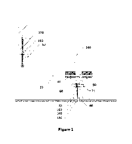
The present invention describes a ventilated facade cladding system comprising
horizontal tracks (20) mounted to a wall gradually. Hanging clips (40) are
placed on the
horizontal tracks (20) and can be slid on them. Brackets (50) are placed
between the
hanging clips (40), fixed in the space between the extension profile (21) and
the hanging
clip (40). Bracket clips (60) are attached to the bracket (50) sliding through
a clip gap
(61). Mullion profiles (70) having T-shape form, wherein vertical part
positioned in desired
depth and fixed between the bracket (50) and the bracket clip (60), wherein
tile (130) is
bonded with horizontal part.
La présente invention concerne un système de revêtement de façade ventilé comprenant des rails horizontaux (20) montés sur une paroi progressivement. Des attaches de suspension (40) sont placées sur les rails horizontaux (20) et peuvent coulisser sur celles-ci. Des supports (50) sont placés entre les pinces de suspension (40), fixés dans l'espace entre le profil d'extension (21) et l'attache de suspension (40). Des attaches de support (60) sont fixées au support (50) coulissant à travers un espace d'attache (61). Des profilés de meneau (70) présentent une forme en T, une partie verticale étant positionnée à une profondeur souhaitée et fixée entre le support (50) et l'attache de support (60), le carreau (130) étant lié à une partie horizontale.
Note: Claims are shown in the official language in which they were submitted.
Note: Descriptions are shown in the official language in which they were submitted.
2024-08-01:As part of the Next Generation Patents (NGP) transition, the Canadian Patents Database (CPD) now contains a more detailed Event History, which replicates the Event Log of our new back-office solution.
Please note that "Inactive:" events refers to events no longer in use in our new back-office solution.
For a clearer understanding of the status of the application/patent presented on this page, the site Disclaimer , as well as the definitions for Patent , Event History , Maintenance Fee and Payment History should be consulted.
| Description | Date |
|---|---|
| Maintenance Fee Payment Determined Compliant | 2024-10-10 |
| Maintenance Request Received | 2024-07-26 |
| Letter Sent | 2024-03-13 |
| Request for Examination Received | 2024-03-12 |
| All Requirements for Examination Determined Compliant | 2024-03-12 |
| Request for Examination Requirements Determined Compliant | 2024-03-12 |
| Inactive: Cover page published | 2024-03-06 |
| Inactive: IPC assigned | 2024-03-05 |
| Inactive: First IPC assigned | 2024-03-05 |
| Inactive: IPC assigned | 2024-03-05 |
| Inactive: IPC assigned | 2024-03-05 |
| Inactive: IPC assigned | 2024-03-05 |
| Application Published (Open to Public Inspection) | 2024-01-26 |
| Inactive: Applicant deleted | 2024-01-22 |
| Inactive: Applicant deleted | 2024-01-22 |
| Application Received - PCT | 2023-12-27 |
| National Entry Requirements Determined Compliant | 2023-12-27 |
| Small Entity Declaration Determined Compliant | 2023-12-27 |
| Letter sent | 2023-12-27 |
There is no abandonment history.
The last payment was received on 2024-07-26
Note : If the full payment has not been received on or before the date indicated, a further fee may be required which may be one of the following
Please refer to the CIPO Patent Fees web page to see all current fee amounts.
| Fee Type | Anniversary Year | Due Date | Paid Date |
|---|---|---|---|
| Basic national fee - small | 2023-12-27 | ||
| Request for examination - small | 2026-07-27 | 2024-03-12 | |
| MF (application, 2nd anniv.) - small | 02 | 2024-07-26 | 2024-07-26 |
Note: Records showing the ownership history in alphabetical order.
| Current Owners on Record |
|---|
| BKUP MIMARLIK ANONIM SIRKETI |
| Past Owners on Record |
|---|
| SERKAN SABRI BAYRAM |

