Note: Descriptions are shown in the official language in which they were submitted.
1
WO 2023/204510
PCT/KR2023/004866
Description
Title of Invention: ACCESSORY FOR AEROSOL GENERATING
DEVICE AND AEROSOL GENERATING SYSTEM INCLUDING
THE SAME
Technical Field
[1] The disclosure relates to an accessory for an aerosol generating
device, for removing
an aerosol generating article remaining within an accommodation space of an
aerosol
generating device and an aerosol generating system including the same,
Background Art
[2] Recently, the demand for alternative methods for overcoming the
shortcomings of
general cigarettes has increased. For example, there is an increasing demand
for a
system for generating aerosols by heating a cigarette or an aerosol generating
material
by using an aerosol generating device, rather than by burning cigarettes.
[31 Recently, aerosol generating devices capable of generating
aerosol by heating aerosol
generating articles have been provided as a way to replace a method of
supplying
aerosol by burning cigarettes. For example, aerosol generating devices may
refer to
devices capable of generating aerosol by heating liquid or solid aerosol
generating
materials via heaters at a certain temperature.
[4] The convenience of user's smoking may be improved, such as
smoking without ad-
ditional items, such as lighters, and smoking as much as the users want, by
using
aerosol generating devices. Therefore, recently, research on aerosol
generating devices
has been gradually increased.
Disclosure of Invention
Technical Problem
[51 An aerosol generating device may generate aerosol by heating
an aerosol generating
article inserted into an accommodation space, and a user may smoke by inhaling
the
generated aerosol.
[6] The user may continue smoking by replacing the aerosol
generating article inserted
into the accommodation space with a new aerosol generating article when use of
the
aerosol generating article is completed, and in the process of replacing the
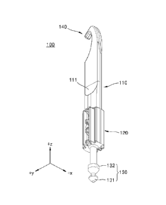
aerosol
generating article, a portion of the used aerosol generating article may
remain within
the accommodation space.
[71 For example, the portion of the aerosol generating article
may be broken in the
process of removing, from the accommodation space, the aerosol generating
article
heated at a high temperature within the aerosol generating device, and the
broken
CA 03224605 2023- 12-29
WO 2023/204510
PCT/KR2023/004866
portion of the aerosol generating article may remain within the accommodation
space.
[81 When the aerosol generating article remains within the
accommodation space of the
aerosol generating device, a new aerosol generating article may not be
inserted into the
accommodation space, and thus, the aerosol generating device may not be used.
Therefore, there is a need for a method of easily removing an aerosol
generating article
remaining within an accommodation space.
[91 The disclosure may enable a user to easily remove an aerosol
generating article
remaining in an accommodation space by providing an accessory for an aerosol
generating device, capable of removing the aerosol generating article
remaining within
the accommodation space of an aerosol generating device.
[10] The technical problems of the present disclosure are not
limited to the above-
described description, and other technical problems may be clearly understood
by one
of ordinary skill in the art from the embodiments to be described hereinafter.
Solution to Problem
1111 According to an aspect of the disclosure, an accessory for
an aerosol generating
device includes a body, a guide unit arranged to surround at least a portion
of an outer
circumferential surface of the body, and a first remover arranged on one side
of the
body, and removing an aerosol generating article remaining in an accommodation
space of the aerosol generating device, wherein the first remover is arranged
to
surround at least one region of one side of the body, and includes a first end
portion
inserted into the aerosol generating article remaining in the accommodation
space and
a second end portion arranged in one region of the body spaced apart from the
first end
portion and supporting at least a portion of the aerosol generating article.
[12] According to another aspect of the disclosure, an aerosol generating
system includes
an aerosol generating device including an accommodation space having an
aerosol
generating article accommodated therein, and a heater to heat the aerosol
generating
article accommodated in the accommodation space, and an accessory for an
aerosol
generating device, removing an aerosol generating article remaining in the
accom-
modation space, wherein the accessory for an aerosol generating device
includes a
body, a guide unit arranged to surround at least a portion of an outer
circumferential
surface of the body, and a first remover arranged to surround at least one
region of one
side of the body, and includes a first end portion inserted into the aerosol
generating
article remaining in the accommodation space and a second end portion arranged
in
one region of the body spaced apart from the first end portion and supporting
at least a
portion of the aerosol generating article.
Advantageous Effects of Invention
[13] In various embodiments, an accessory for an aerosol generating device
may ef-
CA 03224605 2023- 12-29
3
WO 2023/204510
PCT/KR2023/004866
fectively remove an aerosol generating article remaining in an accommodation
space
of an aerosol generating device.
[14] Effects of the present disclosure are not limited to the above
effects, and effects that
are not mentioned could be clearly understood by one of ordinary skill in the
art from
the present specification and the attached drawings.
Brief Description of Drawings
[15] FIG. 1 is a perspective view of an accessory for an aerosol generating
device,
according to an embodiment.
[16] FIG. 2 is a view illustrating a process of removing an aerosol
generating article
remaining in an accommodation space via a first remover of an accessory for an
aerosol generating device in an aerosol generating system, according to an em-
bodiment.
[17] FIG. 3 is an enlarged view illustrating the first remover of the
accessory for an
aerosol generating device illustrated in FIG. 2.
[181 FIG. 4 is a front view illustrating an accessory for an
aerosol generating device,
which is inserted into an accommodation space of an aerosol generating device
in an
aerosol generating system, according to an embodiment.
[19] FIG. 5 is a front view illustrating an accessory for an aerosol
generating device,
which is inserted into an accommodation space of an aerosol generating device
in an
aerosol generating system, according to an embodiment.
[20] FIG. 6 is a view illustrating a process of removing a remaining
aerosol generating
article via a second remover of an accessory for an aerosol generating device
in an
aerosol generating system, according to an embodiment.
[21] FIG. 7 is a perspective view of an accessory for an aerosol generating
device,
according to an embodiment.
[22] FIG. 8 is a view illustrating a process of removing an aerosol
generating article
remaining in an accommodation space of an aerosol generating device via a
first
remover of the accessory for an aerosol generating device illustrated in FIG.
7.
[231 FIG. 9 is a perspective view of an accessory for an aerosol
generating device,
according to an embodiment.
[24] FIG. 10 is a view illustrating a process of removing an aerosol
generating article
remaining in an accommodation space of an aerosol generating device via a
first
remover of the accessory for an aerosol generating device illustrated in FIG.
9.
[25] FIG. 11 is a block diagram of an aerosol generating device according
to an em-
bodiment.
Mode for the Invention
[26] Regarding the terms in the various embodiments, the general terms
which are
CA 03224605 2023- 12-29
4
WO 2023/204510
PCT/KR2023/004866
currently and widely used are selected in consideration of functions of
structural
elements in the various embodiments of the present disclosure. However,
meanings of
the terms can be changed according to intention, a judicial precedence, the
appearance
of a new technology, and the like. In addition, in certain cases, terms which
can be ar-
bitrarily selected by the applicant in particular cases. In such a case, the
meaning of the
terms will be described in detail at the corresponding portion in the
description of the
present disclosure. Therefore, the terms used in the various embodiments of
the present
disclosure should be defined based on the meanings of the terms and the
descriptions
provided herein.
[27] In addition, unless explicitly described to the contrary, the word
"comprise" and
variations such as "comprises" or "comprising" will be understood to imply the
inclusion of stated elements but not the exclusion of any other elements. In
addition,
the terms "-er", "-or", and "module" described in the specification mean units
for
processing at least one function and operation and can be implemented by
hardware
components or software components and combinations thereof.
[28] As used herein, when an expression such as "at least any one" precedes
arranged
elements, it modifies all elements rather than each arranged element. For
example, the
expression "at least any one of a, b, and c" should be construed to include a,
b, c, or a
and b, a and c, b and c, or a, b, and c.
[29] In an embodiment, an aerosol generating device may be a device that
generates
aerosols by electrically heating a cigarette accommodated in an interior space
thereof.
[30] The aerosol generating device may include a heater. In an embodiment,
the heater
may be an electro-resistive heater. For example, the heater may include an
electrically
conductive track, and the heater may be heated when currents flow through the
elec-
trically conductive track.
[31] The heater may include a tube-shaped heating element, a plate-shaped
heating
element, a needle-shaped heating element, or a rod-shaped heating element, and
may
heat the inside or outside of a cigarette according to the shape of a heating
element.
[32] A cigarette may include a tobacco rod and a filter rod. The tobacco
rod may be
formed of sheets, strands, and tiny bits cut from a tobacco sheet. Also, the
tobacco rod
may be surrounded by a heat conductive material. For example, the heat
conductive
material may be, but is not limited to, a metal foil such as aluminum foil.
[33] The filter rod may include a cellulose acetate filter. The filter rod
may include at least
one segment. For example, the filter rod may include a first segment
configured to cool
aerosols, and a second segment configured to filter a certain component in
aerosols.
[34] In another embodiment, the aerosol generating device may be a device
that generates
aerosols by using a cartridge containing an aerosol generating material.
[35] The aerosol generating device may include a cartridge that contains an
aerosol
CA 03224605 2023- 12-29
5
WO 2023/204510
PCT/KR2023/004866
generating material, and a main body that supports the cartridge. The
cartridge may be
detachably coupled to the main body, but is not limited thereto. The cartridge
may be
integrally formed or assembled with the main body, and may also be fixed to
the main
body so as not to be detached from the main body by a user. The cartridge may
be
mounted on the main body while accommodating an aerosol generating material
therein. However, the present disclosure is not limited thereto. An aerosol
generating
material may also be injected into the cartridge while the cartridge is
coupled to the
main body.
[36] The cartridge may contain an aerosol generating material in any one of
various states,
such as a liquid state, a solid state, a gaseous state, a gel state, or the
like. The aerosol
generating material may include a liquid composition. For example, the liquid
com-
position may be a liquid including a tobacco-containing material having a
volatile
tobacco flavor component, or a liquid including a non-tobacco material.
[37] The cartridge may be operated by an electrical signal or a wireless
signal transmitted
from the main body to perform a function of generating aerosols by converting
the
phase of an aerosol generating material inside the cartridge into a gaseous
phase. The
aerosols may refer to a gas in which vaporized particles generated from an
aerosol
generating material are mixed with air.
[381 In another embodiment, the aerosol generating device may
generate aerosols by
heating a liquid composition, and generated aerosols may be delivered to a
user
through a cigarette. That is, the aerosols generated from the liquid
composition may
move along an airflow passage of the aerosol generating device, and the
airflow
passage may be configured to allow aerosols to be delivered to a user by
passing
through a cigarette.
[39] In another embodiment, the aerosol generating device may be a device
that generates
aerosols from an aerosol generating material by using an ultrasonic vibration
method.
At this time, the ultrasonic vibration method may mean a method of generating
aerosols by converting an aerosol generating material into aerosols with
ultrasonic
vibration generated by a vibrator.
[40] The aerosol generating device may include a vibrator, and generate a
short-period
vibration through the vibrator to convert an aerosol generating material into
aerosols.
The vibration generated by the vibrator may be ultrasonic vibration, and the
frequency
band of the ultrasonic vibration may be in a frequency band of about 100 kHz
to about
3.5 MHz, but is not limited thereto.
[41] The aerosol generating device may further include a wick that absorbs
an aerosol
generating material. For example, the wick may be arranged to surround at
least one
area of the vibrator, or may be arranged to contact at least one area of the
vibrator.
[42] As a voltage (for example, an alternating voltage) is applied to the
vibrator, heat and/
CA 03224605 2023- 12-29
6
WO 2023/204510
PCT/KR2023/004866
or ultrasonic vibrations may be generated from the vibrator, and the heat
and/or ul-
trasonic vibrations generated from the vibrator may be transmitted to the
aerosol
generating material absorbed in the wick. The aerosol generating material
absorbed in
the wick may be converted into a gaseous phase by heat and/or ultrasonic
vibrations
transmitted from the vibrator, and as a result, aerosols may be generated.
[43] For example, the viscosity of the aerosol generating material absorbed
in the wick
may be lowered by the heat generated by the vibrator, and as the aerosol
generating
material having a lowered viscosity is granulated by the ultrasonic vibrations
generated
from the vibrator, aerosols may be generated, but is not limited thereto.
[44] In another embodiment, the aerosol generating device is a device that
generates
aerosols by heating an aerosol generating article accommodated in the aerosol
generating device in an induction heating method.
[45] The aerosol generating device may include a susceptor and a coil. In
an embodiment_
the coil may apply a magnetic field to the susceptor. As power is supplied to
the coil
from the aerosol generating device, a magnetic field may be formed inside the
coil. In
an embodiment, the susceptor may be a magnetic body that generates heat by an
external magnetic field. As the susceptor is positioned inside the coil and a
magnetic
field is applied to the susceptor, the susceptor generates heat to heat an
aerosol
generating article. In addition, optionally, the susceptor may be positioned
within the
aerosol generating article.
[46] In another embodiment, the aerosol generating device may further
include a cradle.
[47] The aerosol generating device may configure a system together with a
separate
cradle. For example, the cradle may charge a battery of the aerosol generating
device.
Alternatively, the heater may be heated when the cradle and the aerosol
generating
device are coupled to each other.
[48] Hereinafter, the present disclosure will now be described more fully
with reference to
the accompanying drawings, in which exemplary embodiments of the present
disclosure are shown such that one of ordinary skill in the art may easily
work the
present disclosure. The present disclosure may be implemented in a form that
can be
implemented in the aerosol generating devices of the various embodiments
described
above or may be implemented in various different forms, and is not limited to
the em-
bodiments described herein.
[49] Hereinafter, embodiments of the present disclosure will be described
in detail with
reference to the drawings.
[50] FIG. 1 is a perspective view of an accessory for an aerosol generating
device,
according to an embodiment.
[51] Referring to FIG. 1, an accessory 100 for an aerosol generating
device, according to
an embodiment, may include a body 110, a guide unit 120, a first remover 130,
and a
CA 03224605 2023- 12-29
7
WO 2023/204510
PCT/KR2023/004866
second remover 140. The components of the accessory 100 for an aerosol
generating
device are not limited thereto, and according to embodiments, other components
may
be further included, in addition to the components described above, or at
least one
(e.g., the guide unit 120 and/or the second remover 140) of the components
described
above may be omitted.
[52] The body 110 may extend in a longitudinal direction thereof, and may
form the
overall appearance of the accessory 100 for an aerosol generating device. In
the
disclosure, "the longitudinal direction of the body" may refer to a +z
direction or a -z
direction in FIG. 1, and the corresponding expression may be used in the same
sense
below.
[53] According to an embodiment, a grip groove 111 may be formed in at
least one region
of the body 110, and a user may grip the accessory 100 for an aerosol
generating
device via the grip groove 111. For example, the grip groove 111 may be formed
in a
streamlined shape so that the user may easily grip the accessory 100 for an
aerosol
generating device, but the shape of the grip groove 111 is not limited
thereto.
[54] The guide unit 120 may guide movement of the accessory 100 for an
aerosol
generating device when the accessory 100 for an aerosol generating device is
inserted
into an accommodation space of the aerosol generating device. For example, the
guide
unit 120 may guide movement of the accessory 100 for an aerosol generating
device so
that the accessory 100 for an aerosol generating device moves in a
longitudinal
direction of the accommodation space.
[55] According to an embodiment, the guide unit 120 may be formed to
protrude from an
outer circumferential surface of the body 110 while arranged to surround at
least a
portion of the outer circumferential surface of the body 110 to guide the
movement of
the accessory 100 for an aerosol generating device, but the shape of the guide
unit 120
is not limited to the embodiment described above.
[56] The first remover 130 may be arranged on one side of the body 110, and
may operate
to remove an aerosol generating article (or a cigarette) remaining within the
accom-
modation space of the aerosol generating device. For example, in a process of
replacing the aerosol generating article inserted into the accommodation space
of the
aerosol generating device with a new aerosol generating article, a portion of
the
inserted aerosol generating article may be broken and remain within the accom-
modation space.
[57] The first remover 130 may be arranged on one side of the body 110
facing the -z
direction to remove the aerosol generating article remaining within the
accommodation
space when the accessory 100 for an aerosol generating device is inserted into
the ac-
commodation space.
[58] According to an embodiment, the first remover 130 may include a first
end portion
CA 03224605 2023- 12-29
8
WO 2023/204510
PCT/KR2023/004866
131 and a second end portion 132 for removing the aerosol generating article
remaining within the accommodation space.
[59] The first end portion 131 may pass through the aerosol generating
article remaining
within the accommodation space and be inserted into the aerosol generating
article
when the first remover 130 of the accessory 100 for an aerosol generating
device is
inserted into the accommodation space.
[60] The second end portion 132 may be arranged in one region of the body
110 spaced
apart from the first end portion 131 by a predefined distance, and may support
at least
a portion of the aerosol generating article located between the first end
portion 131 and
the second end portion 132 when the first remover 130 is inserted into the
aerosol
generating article.
[61] In other words, the accessory 100 for an aerosol generating device,
according to an
embodiment, may he inserted into the aerosol generating article via the first
end
portion 131, and then may support, via the second end portion 132, the aerosol
generating article located between the first end portion 131 and the second
end portion
132. As a result, when the accessory 100 for an aerosol generating device is
removed
from the accommodation space, the aerosol generating article remaining within
the ac-
commodation space may be supported by the first end portion 131 and the second
end
portion 132 of the first remover 130 to be removed from the accommodation
space
together with the accessory 100 for an aerosol generating device.
[62] The second remover 140 may be arranged on the other side located in
the opposite
direction to the one side of the body 110, and may operate to remove the
aerosol
generating article remaining within the accommodation space of the aerosol
generating
device. For example, the second remover 140 may be arranged on the other side
of the
body 110 facing the +z direction, and thus may remove the aerosol generating
article
remaining within the accommodation space when the accessory 100 for an aerosol
generating device is inserted into the accommodation space.
[63] According to an embodiment, at least one region of the second remover
140 may be
formed in a hook shape, and may be hooked on at least a portion of the aerosol
generating article remaining within the accommodation space when the second
remover 140 of the accessory 100 for an aerosol generating device is inserted
into the
accommodation space of the aerosol generating device.
[64] Accordingly, when the accessory 100 for an aerosol generating device
is removed
from the accommodation space, the aerosol generating article remaining within
the ac-
commodation space may be removed from the accommodation space together with
the
accessory 100 for an aerosol generating device while hooked on the second
remover
140.
[65] Hereinafter, a process of removing an aerosol generating article
remaining in an ac-
CA 03224605 2023- 12-29
9
WO 2023/204510
PCT/KR2023/004866
commodation space of an aerosol generating device via an accessory 100 for an
aerosol generating device will be described in detail with reference to FIGS.
2 to 6.
[66] FIG. 2 is a view illustrating a process of removing an aerosol
generating article
remaining in an accommodation space via a first remover of an accessory for an
aerosol generating device in an aerosol generating system, according to an em-
bodiment.
[67] Referring to FIG. 2, an aerosol generating system 1000 according to an
embodiment
may include an aerosol generating device 10 and an accessory 100 for an
aerosol
generating device, for removing an aerosol generating article 20 within an
accom-
modation space 10i of the aerosol generating device 10. At least one of
components of
the accessory 100 for an aerosol generating device may be the same as or
similar to at
least one of the components of the accessory 100 for an aerosol generating
device il-
lustrated in FIG. 1, and the same description thereof will be omitted below.
[68] The aerosol generating device 10 may include the accommodation space
10i for ac-
commodating at least a portion of the aerosol generating article 20 and a
heater 12 for
heating the aerosol generating article 20 accommodated or inserted in the
accom-
modation space 10i.
[69] The accommodation space 10i may be formed in a shape corresponding to
an outer
circumferential surface of the aerosol generating article 20 to accommodate at
least a
portion of the aerosol generating article 20. For example, the accommodation
space 10i
may be formed in a cylindrical or elliptical column shape corresponding to a
shape of
the outer circumferential surface of the aerosol generating article 20, but
the shape of
the accommodation space 10i is not limited thereto.
[70] A heater 12 may heat the aerosol generating article 20 accommodated or
inserted in
the accommodation space 10i by generating heat as power is supplied from a
battery
(not shown). When the aerosol generating article 20 is heated by the heater
12, aerosol
may be generated inside the accommodation space 10i, and a user may contact
the
aerosol generating article 20 with the mouth and inhale the generated aerosol.
[71] According to an embodiment, the heater 12 may include an induction
heater. For
example, the heater 12 may include a coil (or an electrically conductive coil)
for
generating an alternating magnetic field as power is supplied, and a susceptor
for
generating heat by the alternating magnetic field generated by the coil. The
susceptor
may be arranged to surround at least a portion of the outer circumferential
surface of
the aerosol generating article 20 accommodated or inserted in the
accommodation
space 10i to heat the inserted aerosol generating article 20.
[72] According to an embodiment, the heater 12 may include an electro-
resistive heater.
For example, the heater 12 may include a film heater arranged to surround at
least a
portion of the outer circumferential surface of the aerosol generating article
20 inserted
CA 03224605 2023- 12-29
10
WO 2023/204510
PCT/KR2023/004866
into the accommodation space 10i. The film heater may include an electrically
conductive track, and the film heater may generate heat as a current flows
through the
electrically conductive track to heat the aerosol generating article 20
inserted into the
accommodation space 10i.
[73] According to an embodiment, the heater 12 may include at least one of
a needle-type
heater, a rod-type heater, and a tube-type heater capable of heating the
inside of the
aerosol generating article 20 inserted into the accommodation space 10i. For
example,
the heater 12 may be inserted into at least one region of the aerosol
generating article
20 to heat the inside of the aerosol generating article 20.
[74] However, the heater 12 of the disclosure is not limited to the
embodiments described
above, and the heater 12 may include other types of heaters that may heat the
aerosol
generating article 20 to a predefined temperature, in addition to the types of
the em-
bodiments described above. In the disclosure, the predefined temperature may
refer to
a temperature at which an aerosol generating material included in the aerosol
generating article 20 may be heated to generate aerosol. The predefined
temperature
may be a temperature preset in the aerosol generating device 10, but the
corresponding
temperature may be changed by a type of aerosol generating device 10 and/or by
an
operation of the user.
1-751 The aerosol generating article 20, which is fully used, needs to
be replaced with a
new aerosol generating article to continue smoking, and when the aerosol
generating
article 20 is heated at a high temperature during use of the aerosol
generating device
10, a portion of the aerosol generating article 20 may be broken during a
removal
process thereof.
[76] The aerosol generating article 20 remaining within the accommodation
space 10i
may not be easily removed by the hands of the user alone, and thus, the broken
portion
of the aerosol generating article 20 may remain within the accommodation space
10i.
When a portion of the aerosol generating article 20 remains in the
accommodation
space 10i, a new aerosol generating article may not be inserted into the
accommodation
space 10i, and thus, a method of removing the aerosol generating article 20
remaining
within the accommodation space 10i is needed for the user to continue smoking.
[77] The aerosol generating system 1000 according to an embodiment may
provide the
accessory 100 for an aerosol generating device, capable of removing the
aerosol
generating article 20 remaining in the accommodation space 10i, and as a
result, the
user may easily and efficiently remove the aerosol generating article 20
remaining
within the accommodation space 10i.
[78] When inserted into the accommodation space 10i, a first remover 130 of
the
accessory 100 for an aerosol generating device may pass through at least a
portion of
the aerosol generating article 20 remaining within the accommodation space 10i
and be
CA 03224605 2023- 12-29
11
WO 2023/204510
PCT/KR2023/004866
inserted into the aerosol generating article 20.
[79] According to an embodiment, the first remover 130 may include a first
end portion
131 arranged on one side of the body 110 and a second end portion 132 arranged
in
one region of the body 110 spaced apart from the first end portion 131 by a
predefined
distance.
[80] When the first remover 130 of the accessory 100 for an aerosol
generating device is
inserted into the accommodation space 10i, the first end portion 131 may
operate to
pass through at least one region of the aerosol generating article 20
remaining in the
accommodation space 10i.
[81] The second end portion 132 may be arranged in one region of the body
110 spaced
apart from the first end portion 131 by the predefined distance, and may
operate to
support the aerosol generating article 20 pressurized between the first end
portion 131
and the second end portion 132 when the first remover 130 is inserted into the
aerosol
generating article 20 together with the first end portion 131.
[82] In other words, the first remover 130 may pass through, via the first
end portion 131,
at least one region of the aerosol generating article 20 remaining within the
accom-
modation space 10i, and then may support, via the first end portion 131 and
the second
end portion 132, the aerosol generating article 20 accommodated between the
first end
portion 131 and the second end portion 132.
[83] Accordingly, when the first remover 130 is removed from the
accommodation space
10i, the aerosol generating article 20 supported by the first end portion 131
and the
second end portion 132 may also be removed from the accommodation space 10i
together with the first remover 130.
[84] A guide unit 120 of the accessory 100 for an aerosol generating device
may guide the
accessory 100 for an aerosol generating device to move in a longitudinal
direction of
the accommodation space 10i (e.g., in the +z direction or the -z direction in
FIG. 2)
when the accessory 100 for an aerosol generating device is inserted into the
accom-
modation space 10i.
[85] For example, when the accessory 100 for an aerosol generating device
is inserted into
the accommodation space 10i in a direction forming a certain angle with the
lon-
gitudinal direction of the accommodation space 10i, the inside of the
accommodation
space 10i may be damaged by the accessory 100 for an aerosol generating
device, or
conversely, the accessory 100 for an aerosol generating device may be damaged.
[86] The accessory 100 for an aerosol generating device, according to an
embodiment,
may prevent damage to the accommodation space 10i or the accessory 100 for an
aerosol generating device, which may occur in an insertion process, by
guiding, via the
guide unit 120, the accessory 100 for an aerosol generating device to move
only in the
longitudinal direction of the accommodation space 10i regardless of an
insertion
CA 03224605 2023- 12-29
1")
WO 2023/204510
PCT/KR2023/004866
direction of the accessory 100 for an aerosol generating device.
[87] Hereinafter, a process of inserting the first remover 130 into the
aerosol generating
article 20 remaining in the accommodation space 10i to support the aerosol
generating
article 20 will be described with reference to FIG. 3.
[88] FIG. 3 is an enlarged view illustrating a first remover of an
accessory for an aerosol
generating device, as illustrated in FIG. 2. Here, FIG. 3 illustrates that a
first remover
130 is inserted into an aerosol generating article 20 remaining in an
accommodation
space 10i.
[89] Referring to FIG. 3, an accessory 100 for an aerosol generating device
(e.g., the
accessory 100 for an aerosol generating device of FIG. 1 or 2), according to
an em-
bodiment, may include a body 110 (e.g., the body 110 of FIG. 2) and the first
remover
130 (e.g., the first remover 130 of FIG. 1) arranged on one side of the body
110 to
remove the aerosol generating article 20.
[90] The first remover 130 may include a first end portion 131 and a second
end portion
132, and may pass through the aerosol generating article 20 remaining in the
accom-
modation space (e.g., the accommodation space 10i of FIG.2) of an aerosol
generating
device (e.g., the aerosol generating device 10 of FIG. 2) and may be inserted
into the
aerosol generating article 20.
[911 The first end portion 131 may be located at an end of one
side of the body 110, and
may pass through the aerosol generating article 20 remaining within the accom-
modation space and be inserted into the aerosol generating article 20 when the
first
remover 130 is inserted into the accommodation space.
[92] The first end portion 131 may include a first inclined surface 131i
forming a first
angle 0, with a longitudinal direction L of the body 110 to effectively pass
through the
aerosol generating article 20 remaining within the accommodation space 10i.
[93] In addition, the second end portion 132 may be spaced apart from the
first end
portion 131, and may include a second inclined surface 132i forming a second
angle 02
with the longitudinal direction L of the body 110 to support aerosol
generating article
accommodated in a space (a region A in FIG. 3) between the first end portion
131 and
the second end portion 132 when the first remover 130 is inserted into the
aerosol
generating article 20.
[94] [Table 11
AI 5 100 200 300 400 500 55 60 70'
02
30 5% 37% 51% 72% 90% 87% 0
0 0
400 3% 36% 54% 73% 92% 90% 0
0 0
50 2% 40% 57% 76% 93% 91% 0
0 0
CA 03224605 2023- 12-29
13
WO 2023/204510
PCT/KR2023/004866
[951
[96] Table 1 shows a ratio of a volume of the aerosol generating article 20
accommodated
in the space A to a volume of the space A between the first end portion 131
and the
second end portion 132, according to sizes of the first angle 01 and the
second angle 02.
[97] Referring to Table 1, when the first angle 01 becomes less than 10 in
a condition in
which the second angle 02 is about 30 to about 50 , the aerosol generating
article 20
may little be accommodated in the space A between the first end portion 131
and the
second end portion 132. In contrast, when the first angle 01 is greater than
50% the first
end portion 131 may not pass through the aerosol generating article 20, and
thus, the
aerosol generating article 20 may not be accommodated in the space A between
the
first end portion 131 and the second end portion 132.
[98] An amount of aerosol generating article 20, which is larger than or
equal to a
predefined amount, needs to be accommodated in the space A between the first
end
portion 131 and the second end portion 132, so that the aerosol generating
article 20
remaining in the accommodation space 10i is removed together when the
accessory
100 for an aerosol generating device is removed from the accommodation space.
[99] In the accessory 100 for an aerosol generating device, according to an
embodiment,
the first angle 01 may be about 10 to about 50% and the second angle 02 may
be about
30 to about 40 , so that a predefined amount of aerosol generating article 20
may be
accommodated in the space A between the first end portion 131 and the second
end
portion 132. For example, the first angle 01 may be about 46 to about 48 ,
and the
second angle 02 may be about 42 to about 44 , but is not limited thereto.
[100] According to an embodiment, the second end portion 132 may be
arranged in one
region of the body 110 spaced apart from the first end portion 131 by a
predefined
distance d, so that a sufficient amount of the aerosol generating article 20
is ac-
commodated in the space A between the first end portion 131 and the second end
portion 132 when the first remover 130 is inserted into the aerosol generating
article
20.
[101] The space A between the first end portion 131 and the second end
portion 132 is
great, and thus, the first end portion 131 and the second end portion 132 may
more
strongly support the aerosol generating article 20 when a large amount of
aerosol
generating article 20 is accommodated in the space A.
[102] In addition, as the first end portion 131 and the second end portion
132 strongly
support the aerosol generating article 20, the aerosol generating article 20
may not be
separated from the first remover 130 and may be removed from the accommodation
space 10i together with the first remover 130 when the first remover 130 is
removed
from the accommodation space 10i.
[103] In the accessory 100 for an aerosol generating device, according to
an embodiment,
CA 03224605 2023- 12-29
14
WO 2023/204510
PCT/KR2023/004866
the second end portion 132 may be spaced apart from the first end portion 131
by the
predefined distance d, and thus, a sufficient space may be formed between the
first end
portion 131 and the second end portion 132. For example, the second end
portion 132
may be spaced apart from the first end portion 131 by a distance of about 1 mm
to
about 1.6 mm, and as a result, a sufficient space may be formed between the
first end
portion 131 and the second end portion 132.
[104] In summary, the accessory 100 for an aerosol generating device,
according to an em-
bodiment, may enable a predefined amount of aerosol generating article to be
ac-
commodated in the space A between the first end portion 131 and the second end
portion 132, via the first end portion 131 having a first inclined surface
131i and the
second end portion 132 spaced apart from the first end portion 131 by the
predefined
distance d and having a second inclined surface 132i.
[105] Accordingly, when the first remover 130 of the accessory 100 for an
aerosol
generating device, according to an embodiment, is removed from the
accommodation
space 10i, at least a portion of the aerosol generating article 20 remaining
within the
accommodation space 10i may be removed from the accommodation space 10i
together with the first remover 130 while accommodated in the first remover
130.
[106] In other words, a user may effectively remove the aerosol generating
article 20
remaining in the accommodation space 10i, which may not be removed by the
hands of
the user, by inserting the first remover 130 of the accessory 100 for an
aerosol
generating device into the accommodation space 10i and then removing the first
remover 130 from the accommodation space 10i.
[107] FIG. 4 is a front view illustrating an accessory for an aerosol
generating device,
which is inserted into an accommodation space of an aerosol generating device
in an
aerosol generating system, according to an embodiment.
[108] Referring to FIG. 4, an aerosol generating system 1000 according to
an embodiment
may include an aerosol generating device 10 including an accommodation space
10i
and an accessory 100 for an aerosol generating device, for removing an aerosol
generating article remaining in the accommodation space 10i.
[109] The accessory 100 for an aerosol generating device may include a
guide unit 120 for
guiding movement of the accessory 100 for an aerosol generating device when
inserted
into the accommodation space 10i.
[110] The guide unit 120 may be arranged to surround an outer
circumferential surface of
the accessory 100 for an aerosol generating device, and may guide the
accessory 100
for an aerosol generating device to move in a longitudinal direction of the
accom-
modation space 10i regardless of a direction in which the accessory 100 for an
aerosol
generating device is inserted into the accommodation space 10i.
[111] The accommodation space 10i of the aerosol generating device 10 may
have a guide
CA 03224605 2023- 12-29
15
WO 2023/204510
PCT/KR2023/004866
groove 11 formed therein in a shape corresponding to an outer circumferential
surface
of the guide unit 120. The guide groove 11 may operate to prevent the guide
unit 120
from deviating from the accommodation space 101 when the accessory 100 for an
aerosol generating device is inserted into the accommodation space 10i.
[112] According to an embodiment, a diameter DI of the guide unit 120 of
the accessory
100 for an aerosol generating device may be less than a diameter D2 of the
accom-
modation space 10i. In the disclosure, the diameter DI of the guide unit may
refer to a
diameter of a virtual circle connecting an outermost portion of the guide unit
120, and
the diameter D2 of the accommodation space 10i may refer a diameter of an
inner
surface of the accommodation space 10i. Here, the corresponding expressions
may be
used in the same sense hereinafter.
[113] For example, the diameter DI of the guide unit 120 may be about 7 mm
to about 8
mm, and a distance between the outermost portion of the guide unit 120 and the
inner
surface of the accommodation space 101 may be about 0.1 mm to about 0.2 mm
while
the accessory 100 for an aerosol generating device is inserted in the center
of the ac-
commodation space 10i. However, the diameter DI of the guide unit 120 and/or
the
diameter D2 of the accommodation space 10i are not limited to the embodiment
described above.
[114] According to an embodiment, the guide unit 120 may include at least
one rib 121
protruding from a body (e.g., the body 110 of FIG. 2) of the accessory 100 for
an
aerosol generating device.
[115] The at least one rib 121 may protrude from an outer circumferential
surface of the
body toward the inner surface of the accommodation space 10i, and may guide
the
accessory 100 for an aerosol generating device to move in a longitudinal
direction of
the accommodation space 10i when the accessory 100 for an aerosol generating
device
is inserted into the accommodation space 10i.
[1161 For example, the at least one rib 121 may be radially
arranged on the basis of a lon-
gitudinal direction of the accessory 100 for an aerosol generating device, but
the ar-
rangement structure of the at least one rib 121 is not limited thereto.
[117] The accessory 100 for an aerosol generating device, according to an
embodiment,
may guide, via the guide unit 120, a movement direction of the accessory 100
for an
aerosol generating device within the accommodation space 10i, so that a first
remover
(the first remover 130 of FIG. 1) and/or a second remover (the second remover
140 of
FIG. 1) may be inserted, in a predefined direction, into the aerosol
generating article
remaining within the accommodation space 10i.
[118] FIG. 5 is a front view illustrating an accessory for an aerosol
generating device,
which is inserted into an accommodation space of an aerosol generating device
in an
aerosol generating system, according to an embodiment.
CA 03224605 2023- 12-29
16
WO 2023/204510
PCT/KR2023/004866
1_1191 Referring to FIG. 5, an aerosol generating system 1000
according to an embodiment
may include an aerosol generating device 10 including an accommodation space
10i
and an accessory 100 for an aerosol generating device, for removing an aerosol
generating article remaining in the accommodation space 10i.
[120] The aerosol generating system 1000 according to an embodiment may be
a system in
which only the shape of the guide unit 120 is changed in the aerosol
generating system
1000 of FIG. 4, and the same description thereof will be omitted below.
[121] A guide unit 120 may include at least one rib 121 for guiding
movement of the
accessory 100 for an aerosol generating device when the accessory 100 for an
aerosol
generating device is inserted into the accommodation space 10i.
[122] The at least one rib 121 may protrude from an outer circumferential
surface of a body
toward an inner surface of the accommodation space 10i, and may guide the
accessory
100 for an aerosol generating device to move in a longitudinal direction of
the accom-
modation space 10i when the accessory 100 for an aerosol generating device is
inserted
into the accommodation space 10i.
[123] According to an embodiment, the at least one rib 121 may be arranged
in a "+" shape
on the basis of the body when viewed from the top of the aerosol generating
system
1000 (e.g., in the +z direction in FIG. 2).
11241 In addition, a guide groove 11 of the accommodation space
10i may have formed
therein a recess groove 11h for accommodating the at least one rib 121
arranged in the
"+" shape. For example, the recess groove 11h may be formed in a shape corre-
sponding to the at least one rib 121 to accommodate the at least one rib 121.
[125] As the at least one rib 121 of the guide unit 120 is accommodated in
the recess
groove 11h when the accessory 100 for an aerosol generating device is inserted
into the
accommodation space 10i, the accessory 100 for an aerosol generating device
may
move in a longitudinal direction of the accommodation space 10i without
deviating
from the accommodation space 10i.
[126] FIG. 6 is a view illustrating a process of removing a remaining
aerosol generating
article via a second remover of an accessory for an aerosol generating device
in an
aerosol generating system, according to an embodiment.
[127] Referring to FIG. 6, an aerosol generating system 1000 according to
an embodiment
may include an aerosol generating device 10 and an accessory 100 for an
aerosol
generating device, for removing an aerosol generating article 20 remaining
within an
accommodation space 10i of the aerosol generating device 10. At least one of
components of the aerosol generating system 1000 may be the same as or similar
to at
least one of the components of the aerosol generating system 1000 illustrated
in FIG. 2,
and the same description thereof will be omitted below.
[128] The aerosol generating system 1000 may provide the accessory 100 for
an aerosol
CA 03224605 2023- 12-29
17
WO 2023/204510
PCT/KR2023/004866
generating device, capable of removing the aerosol generating article 20
remaining in
the accommodation space 10i, and as a result, a user may easily and
efficiently remove
the aerosol generating article 20 within the accommodation space 10i, which
may not
be removed by the hands of the user.
[129] According to an embodiment, the accessory 100 for an aerosol
generating device
may include a body 110 and a second remover 140 arranged on the other side of
the
body 110 (e.g., on one side in the -z direction in FIG. 1).
[130] The second remover 140 may operate to remove the aerosol generating
article 20
remaining within the accommodation space 10i of the aerosol generating device
10.
For example, the second remover 140 may be formed in a hook shape to be hooked
on
at least a portion of the aerosol generating article 20, but the shape of the
second
remover 140 is not limited thereto, and the second remover 140 may have any
shape
that may be hooked on the aerosol generating article 20.
[131] Accordingly, when the accessory 100 for an aerosol generating device
is removed
from the accommodation space 10i, the aerosol generating article 20 remaining
within
the accommodation space 101 may be removed from the accommodation space 101
together with the accessory 100 for an aerosol generating device while hooked
on the
second remover 140.
11321 In particular, when only an amount of aerosol generating
article, in which a first
remover may not be inserted, remains in the accommodation space 10i, the user
may
effectively remove, via the second remover 140 of the accessory 100 for an
aerosol
generating device, the aerosol generating article 20 remaining in the
accommodation
space 10i.
[133] FIG. 7 is a perspective view of an accessory for an aerosol
generating device,
according to an embodiment.
[134] Referring to FIG. 7, an accessory 100 for an aerosol generating
device, according to
an embodiment, may include a body 110, a guide unit 120, a first remover 130,
a
second remover 140, and at least one protrusion 150.
[135] The accessory 100 for an aerosol generating device, according to an
embodiment,
may be an accessory in which the at least one protrusion 150 is added to the
accessory
100 for an aerosol generating device illustrated in FIG. 1, and the same
description
thereof will be omitted below.
[136] The at least one protrusion 150 may extend from one region of the
guide unit 120
toward the first remover 130, and may support an aerosol generating article
remaining
in an accommodation space of an aerosol generating device, together with the
first
remover 130.
[137] The accessory 100 for an aerosol generating device, according to an
embodiment,
may prevent the aerosol generating article remaining in the accommodation
space from
CA 03224605 2023- 12-29
18
WO 2023/204510
PCT/KR2023/004866
deviating from the accessory 100 for an aerosol generating device, via the at
least one
protrusion 150 capable of supporting the aerosol generating article together
with the
first remover 130.
[138] Hereinafter, a process of removing an aerosol generating article in
an accom-
modation space via the first remover 130 and the at least one protrusion 150
of the
accessory 100 for an aerosol generating device, according to an embodiment,
will be
described in detail with reference to FIG. 8.
[139] FIG. 8 is a view illustrating a process of removing an aerosol
generating article
remaining in an accommodation space of an aerosol generating device, via a
first
remover of an accessory for an aerosol generating device as illustrated in
FIG. 7.
[140] Referring to FIG. 8, an accessory 100 for an aerosol generating
device, according to
an embodiment, may include a body 110, a guide unit 120, a first remover 130,
and at
least one protrusion 150.
[141] The first remover 130 and the at least one protrusion 150 may pass
through at least a
portion of an aerosol generating article 20 remaining in an accommodation
space 10i
of an aerosol generating device (e.g., the aerosol generating device 10 of
FIG. 2) and
be inserted into the aerosol generating article 20 when the accessory 100 for
an aerosol
generating device is inserted in the accommodation space 10i.
11421 When the accessory 100 for an aerosol generating device is
inserted into the accom-
modation space 10i, a first end portion 131 and a second end portion 132 of
the first
remover 130 may support at least a portion of the aerosol generating article
20 ac-
commodated in a space (the region A of FIG. 3) between the first end portion
131 and
the second end portion 132.
[143] In addition, the at least one protrusion 150 may pressurize the
aerosol generating
article 20 remaining in the accommodation space 10i in a direction toward the
body
110 (in a direction indicated by arrows in FIG. 8) when the accessory 100 for
an
aerosol generating device is inserted into the accommodation space 10i, so
that at least
a portion of the aerosol generating article 20 may be accommodated between the
body
110 and the at least one protrusion 150. The body 110 and the at least one
protrusion
150 may support at least a portion of the aerosol generating article 20
accommodated
between the body 110 and the at least one protrusion 150.
[144] In other words, the accessory 100 for an aerosol generating device,
according to an
embodiment, may more strongly support the aerosol generating article 20
remaining in
the accommodation space 10i, via the at least one protrusion 150 supporting
the
aerosol generating article 20 together with the first remover 130.
[145] Accordingly, the accessory 100 for an aerosol generating device,
according to an em-
bodiment, may enable the aerosol generating article 20 to be removed from the
accom-
modation space 10i together with the accessory 100 for an aerosol generating
device
CA 03224605 2023- 12-29
19
WO 2023/204510
PCT/KR2023/004866
without deviating from the accessory 100 for an aerosol generating device when
the
accessory 100 for an aerosol generating device is removed from the
accommodation
space 10i.
[146] FIG. 9 is a perspective view of an accessory for an aerosol
generating device,
according to an embodiment.
[147] Referring to FIG. 9, an accessory 100 for an aerosol generating
device, according to
an embodiment, may include a body 110, a guide unit 120, a first remover 130,
a
second remover 140, at least one protrusion 150, and a connector 160.
[148] The accessory 100 for an aerosol generating device, according to an
embodiment,
may be an accessory in which the connector 160 is added to the accessory 100
for an
aerosol generating device illustrated in FIG. 7, and the same description
thereof will be
omitted below.
[149] The connector 160 may arranged to connect the body 110 to the at
least one
protrusion 150, so that the body 110 and the at least one protrusion 150 may
strongly
support an aerosol generating article. For example, when one end of the
connector 160
is connected to the body 110 and the other end thereof is connected to the at
least one
protrusion 150, the body 110 and the at least one protrusion 150 may be
connected to
each other via the connector 160.
[150] In addition, the connector 160 may prevent the at least one
protrusion 150 from being
damaged by the aerosol generating article when the at least one protrusion 150
is
inserted into the aerosol generating article remaining in an accommodation
space.
[151] For example, when the at least one protrusion 150 is inserted into
the aerosol
generating article remaining in the accommodation space, stress (e.g., bending
stress)
may be applied to one end of the at least one protrusion 150 by the aerosol
generating
article, and thus, the at least one protrusion 150 may be bent or broken.
[152] In addition, the accessory 100 for an aerosol generating device,
according to an em-
bodiment, may prevent the at least one protrusion 150 from being bent when the
accessory 100 for an aerosol generating device is inserted into the
accommodation
space, by connecting the body 110 to the at least one protrusion 150 via the
connector
160.
[153] Hereinafter, a process of removing an aerosol generating article
remaining in an ac-
commodation space of an aerosol generating device via the accessory 100 for an
aerosol generating device, according to an embodiment, will be described in
detail with
reference to FIG. 10.
[154] FIG. 10 is a view illustrating a process of removing an aerosol
generating article
remaining in an accommodation space of an aerosol generating device via a
first
remover of an accessory for an aerosol generating device as illustrated in
FIG. 9.
[155] Referring to FIG. 10, an accessory 100 for an aerosol generating
device, according to
CA 03224605 2023- 12-29
20
WO 2023/204510
PCT/KR2023/004866
an embodiment, may include a body 110, a guide unit 120, a first remover 130,
at least
one protrusion 150, and a connector 160.
[156] The first remover 130 and the at least one protrusion 150 may pass
through at least a
portion of an aerosol generating article 20 remaining in an accommodation
space 10i
of an aerosol generating device (e.g., the aerosol generating device 10 of
FIG. 2) and
be inserted into the aerosol generating article 20 when the accessory 100 for
an aerosol
generating device is inserted in the accommodation space 10i.
[157] Bending stress may be applied to the at least one protrusion 150 when
the at least one
protrusion 150 passes through the aerosol generating article 20 remaining in
the ac-
commodation space 10i, and thus, the at least one protrusion 150 may be bent
or
damaged.
[1581 The accessory 100 for an aerosol generating device, according to
an embodiment,
may prevent, via the connector 160 connecting the body 110 to the at least one
protrusion 150, the at least one protrusion 150 from being bent by the bending
stress
applied to the at least one protrusion 150.
[159] In addition, the connector 160 may pressurize the aerosol generating
article 20
remaining in the accommodation space 10i into a space between the body 110 and
the
at least one protrusion 150 when the accessory 100 for an aerosol generating
device is
inserted into the accommodation space 10i, so that at least a portion of the
aerosol
generating article 20 may be accommodated between the body 110 and the at
least one
protrusion 150.
[160] Accordingly, a larger amount of aerosol generating article 20 may be
accommodated
in a space between the body 110 and the at least one protrusion 150, and thus,
the body
110 and the at least one protrusion 150 may more strongly support the aerosol
generating article 20.
[161] In other words, via the connector 160, the accessory 100 for an
aerosol generating
device, according to an embodiment, may prevent the at least one protrusion
150 from
being bent when using the accessory 100 for an aerosol generating device, and
may
prevent the aerosol generating article 20 accommodated in the accommodation
space
10i from deviating from the accessory 100 for an aerosol generating device.
[162] FIG. 11 is a block diagram of an aerosol generating device according
to an em-
bodiment. Here, an aerosol generating device 1100 of FIG. 11 may be
substantially the
same as or similar to the aerosol generating device 10 of the aerosol
generating system
1000 illustrated FIG. 2.
[163] The aerosol generating device 1100 may include a controller 1110, a
sensing unit
1120, an output unit 1130, a battery 1140, a heater 1150, a user input unit
1160, a
memory 1170, and a communication unit 1180. However, the internal structure of
the
aerosol generating device 1100 is not limited to those illustrated in FIG. 11.
In other
CA 03224605 2023- 12-29
21
WO 2023/204510
PCT/KR2023/004866
words, according to the design of the aerosol generating device 1100, it will
be un-
derstood by one of ordinary skill in the art that some of the components shown
in FIG.
11 may be omitted or new components may be added.
[164] The sensing unit 1120 may sense a state of the aerosol generating
device 1100 and a
state around the aerosol generating device 1100, and transmit sensed
information to the
controller 1110. Based on the sensed information, the controller 1110 may
control the
aerosol generating device 1100 to perform various functions, such as
controlling an
operation of the heater 1150, limiting smoking, determining whether an aerosol
generating article (e.g., a cigarette, a cartridge, or the like) is inserted,
displaying a no-
tification, or the like.
[165] The sensing unit 1120 may include at least one of a temperature
sensor 1122, an
insertion detection sensor, and a puff sensor 1126, but is not limited
thereto.
[166] The temperature sensor 1122 may sense a temperature at which the
heater 1150 (or
an aerosol generating material) is heated. The aerosol generating device 1100
may
include a separate temperature sensor for sensing the temperature of the
heater 1150, or
the heater 1150 may serve as a temperature sensor. Alternatively, the
temperature
sensor 1122 may also be arranged around the battery 1140 to monitor the
temperature
of the battery 1140.
[167] The insertion detection sensor 1124 may sense insertion and/or
removal of an aerosol
generating article. For example, the insertion detection sensor 1124 may
include at
least one of a film sensor, a pressure sensor, an optical sensor, a resistive
sensor, a ca-
pacitive sensor, an inductive sensor, and an infrared sensor, and may sense a
signal
change according to the insertion and/or removal of an aerosol generating
article.
[168] The puff sensor 1126 may sense a user's puff on the basis of various
physical
changes in an airflow passage or an airflow channel. For example, the puff
sensor 1126
may sense a user's puff on the basis of any one of a temperature change, a
flow change,
a voltage change, and a pressure change.
[169] The sensing unit 1120 may include, in addition to the temperature
sensor 1122, the
insertion detection sensor 1124, and the puff sensor 1126 described above, at
least one
of a temperature/humidity sensor, a barometric pressure sensor, a magnetic
sensor, an
acceleration sensor, a gyroscope sensor, a location sensor (e.g., a global
positioning
system (GPS)), a proximity sensor, and a red-green-blue (RGB) sensor
(illuminance
sensor). Because a function of each of sensors may be intuitively inferred by
one of
ordinary skill in the art from the name of the sensor, a detailed description
thereof may
be omitted.
[170] The output unit 1130 may output information on a state of the aerosol
generating
device 1100 and provide the information to a user. The output unit 1130 may
include at
least one of a display unit 1132, a haptic unit 1134, and a sound output unit
1136, but
CA 03224605 2023- 12-29
WO 2023/204510
PCT/KR2023/004866
is not limited thereto. When the display unit 1132 and a touch pad form a
layered
structure to form a touch screen, the display unit 1132 may also be used as an
input
device in addition to an output device.
[171] The display unit 1132 may visually provide information about the
aerosol generating
device 1100 to the user. For example, information about the aerosol generating
device
1100 may mean various pieces of information, such as a charging/discharging
state of
the battery 1140 of the aerosol generating device 1100, a preheating state of
the heater
1150, an insertion/removal state of an aerosol generating article, or a state
in which the
use of the aerosol generating device 1100 is restricted (e.g., sensing of an
abnormal
object), or the like, and the display unit 1132 may output the information to
the
outside. The display unit 1132 may be, for example, a liquid crystal display
panel
(LCD), an organic light-emitting diode (OLED) display panel, or the like. In
addition,
the display unit 1132 may be in the form of a light-emitting diode (LED) light-
emitting
device.
[172] The haptic unit 1134 may tactilely provide information about the
aerosol generating
device 1100 to the user by converting an electrical signal into a mechanical
stimulus or
an electrical stimulus. For example, the haptic unit 1134 may include a motor,
a piezo-
electric element, or an electrical stimulation device.
[1731 The sound output unit 1136 may audibly provide information
about the aerosol
generating device 1100 to the user. For example, the sound output unit 1136
may
convert an electrical signal into a sound signal and output the same to the
outside.
[174] The battery 1140 may supply power used to operate the aerosol
generating device
1100. The battery 1140 may supply power such that the heater 1150 may be
heated. In
addition, the battery 1140 may supply power required for operations of other
components (e.g., the sensing unit 1120, the output unit 1130, the user input
unit 1160,
the memory 1170, and the communication unit 1180) in the aerosol generating
device
1100. The battery 1140 may be a rechargeable battery or a disposable battery.
For
example, the battery 1140 may be a lithium polymer (LiPoly) battery, but is
not limited
thereto.
[175] The heater 1150 may receive power from the battery 1140 to heat an
aerosol
generating material. Although not illustrated in FIG. 11, the aerosol
generating device
1100 may further include a power conversion circuit (e.g., a direct current
(DC)/DC
converter) that converts power of the battery 1140 and supplies the same to
the heater
1150. In addition, when the aerosol generating device 1100 generates aerosols
in an
induction heating method, the aerosol generating device 1100 may further
include a
DC/alternating current (AC) that converts DC power of the battery 1140 into AC
power.
[176] The controller 1110, the sensing unit 1120, the output unit 1130, the
user input unit
CA 03224605 2023- 12-29
23
WO 2023/204510
PCT/KR2023/004866
1160, the memory 1170, and the communication unit 1180 may each receive power
from the battery 1140 to perform a function. Although not illustrated in FIG.
11, the
aerosol generating device 1100 may further include a power conversion circuit
that
converts power of the battery 1140 to supply the power to respective
components, for
example, a low dropout (LDO) circuit, or a voltage regulator circuit.
[177] In an embodiment, the heater 1150 may be formed of any suitable
electrically
resistive material. For example, the suitable electrically resistive material
may be a
metal or a metal alloy including titanium, zirconium, tantalum, platinum,
nickel,
cobalt, chromium, hafnium, niobium, molybdenum, tungsten, tin, gallium,
manganese,
iron, copper, stainless steel, nichrome, or the like, but is not limited
thereto. In
addition, the heater 1150 may be implemented by a metal wire, a metal plate on
which
an electrically conductive track is arranged, a ceramic heating element, or
the like, but
is not limited thereto.
[178] In another embodiment, the heater 1150 may be a heater of an
induction heating type.
For example, the heater 1150 may include a susceptor that heats an aerosol
generating
material by generating heat through a magnetic field applied by a coil.
[179] The user input unit 1160 may receive information input from the user
or may output
information to the user. For example, the user input unit 1160 may include a
key pad, a
dome switch, a touch pad (a contact capacitive method, a pressure resistance
film
method, an infrared sensing method, a surface ultrasonic conduction method, an
integral tension measurement method, a piezo effect method, or the like), a
jog wheel,
a jog switch, or the like, but is not limited thereto. In addition, although
not illustrated
in FIG. 11, the aerosol generating device 1100 may further include a
connection
interface, such as a universal serial bus (USB) interface, and may connect to
other
external devices through the connection interface, such as the USB interface,
to
transmit and receive information, or to charge the battery 1140.
[180] The memory 1170 is a hardware component that stores various types of
data
processed in the aerosol generating device 1100, and may store data processed
and data
to be processed by the controller 1110. The memory 1170 may include at least
one
type of storage medium from among a flash memory type, a hard disk type, a
multimedia card micro type memory, a card-type memory (for example, secure
digital
(SD) or extreme digital (XD) memory, etc.), random access memory (RAM), static
random access memory (SRAM), read-only memory (ROM), electrically erasable pro-
grammable read-only memory (EEPROM), programmable read-only memory
(PROM), a magnetic memory, a magnetic disk, and an optical disk. The memory
1170
may store an operation time of the aerosol generating device 1100, the maximum
number of puffs, the current number of puffs, at least one temperature
profile, data on a
user's smoking pattern, and the like.
CA 03224605 2023- 12-29
24
WO 2023/204510
PCT/KR2023/004866
[1811 The communication unit 1180 may include at least one
component for commu-
nication with another electronic device. For example, the communication unit
1180
may include a short-range wireless communication unit 1182 and a wireless
commu-
nication unit 1184.
[182] The short-range wireless communication unit 1182 may include a
Bluetooth commu-
nication unit, a Bluetooth Low Energy (BLE) communication unit, a near field
com-
munication unit, a wireless LAN (WLAN) (Wi-Fi) communication unit, a Zigbee
com-
munication unit, an infrared data association (IrDA) communication unit, a Wi-
Fi
Direct (WFD) communication unit, an ultra-wideband (UWB) communication unit,
an
Ant+ communication unit, or the like, but is not limited thereto.
[183] The wireless communication unit 1184 may include a cellular network
commu-
nication unit, an Internet communication unit, a computer network (e.g., local
area
network (LAN) or wide area network (WAN)) communication unit, or the like, but
is
not limited thereto. The wireless communication unit 1184 may also identify
and au-
thenticate the aerosol generating device 1100 within a communication network
by
using subscriber information (e.g., International Mobile Subscriber Identifier
(IMSI)).
[184] The controller 1110 may control general operations of the aerosol
generating device
1100. In an embodiment, the controller 1110 may include at least one
processor. The
processor may be implemented as an array of a plurality of logic gates or may
be im-
plemented as a combination of a general-purpose microprocessor and a memory in
which a program executable by the microprocessor is stored. It will be
understood by
one of ordinary skill in the art that the processor may be implemented in
other forms of
hardware.
[185] The controller 1110 may control the temperature of the heater 1150 by
controlling
supply of power of the battery 1140 to the heater 1150. For example, the
controller
1110 may control power supply by controlling switching of a switching element
between the battery 1140 and the heater 1150. In another example, a direct
heating
circuit may also control power supply to the heater 1150 according to a
control
command of the controller 1110.
[186] The controller 1110 may analyze a result sensed by the sensing unit
1120 and control
subsequent processes to be performed. For example, the controller 1110 may
control
power supplied to the heater 1150 to start or end an operation of the heater
1150 on the
basis of a result sensed by the sensing unit 1120. As another example, the
controller
1110 may control, based on a result sensed by the sensing unit 1120, an amount
of
power supplied to the heater 1150 and the time the power is supplied, such
that the
heater 1150 may be heated to a certain temperature or maintained at an
appropriate
temperature.
[187] The controller 1110 may control the output unit 1130 on the basis of
a result sensed
CA 03224605 2023- 12-29
25
WO 2023/204510
PCT/KR2023/004866
by the sensing unit 1120. For example, when the number of puffs counted
through the
puff sensor 1126 reaches a preset number, the controller 1110 may notify the
user that
the aerosol generating device 1100 will soon be terminated through at least
one of the
display unit 1132, the haptic unit 1134, and the sound output unit 1136.
[188] One embodiment may also be implemented in the form of a computer-
readable
recording medium including instructions executable by a computer, such as a
program
module executable by the computer. The computer-readable recording medium may
be
any available medium that may be accessed by a computer and includes both
volatile
and nonvolatile media, and removable and non-removable media. In addition, the
computer-readable recording medium may include both a computer storage medium
and a communication medium. The computer storage medium includes all of
volatile
and nonvolatile media, and removable and non-removable media implemented by
any
method or technology for storage of information such as computer-readable in-
structions, data structures, program modules, or other data. The communication
medium typically includes computer-readable instructions, data structures,
other data
in modulated data signals such as program modules, or other transmission
mechanisms, and includes any information transfer media.
[189] The descriptions of the above-described embodiments are merely
examples, and it
will be understood by one of ordinary skill in the art that various changes
and
equivalents thereof may be made. Therefore, the scope of the disclosure should
be
defined by the appended claims, and all differences within the scope
equivalent to
those described in the claims will be construed as being included in the scope
of
protection defined by the claims.
CA 03224605 2023- 12-29