Note: Descriptions are shown in the official language in which they were submitted.
AEROSOL SOURCE FOR A VAPOUR PROVISION SYSTEM
Technical Field
The present disclosure relates to an aerosol source for an electronic vapour
provision
system such as an e-cigarette.
Background
Many electronic vapour provision systems, such as e-cigarettes and other
electronic
nicotine delivery systems that deliver nicotine via vaporised liquids, and
hybrid devices which
additionally include a portion of tobacco or other flavour element through
which vapour
generated from a liquid is passed, are formed from two main components or
sections,
namely a cartomiser and a control unit (battery section). The cartomiser
generally includes a
reservoir of liquid and an atomiser for vaporising the liquid. These parts may
collectively be
designated as an aerosol source. The atomiser may be implemented as an
electrical
(resistive) heater, such as a wire formed into a coil or other shape, and a
wicking element in
proximity to the heater which transports liquid from the reservoir to the
heater. The control
unit generally includes a battery for supplying power to the atomiser.
Electrical power from
the battery is delivered to the heater, which heats up to vaporise a small
amount of liquid
delivered by the wicking element from the reservoir. The vaporised liquid is
then inhaled by
the user.
The reservoir has an at least one opening by which liquid can leave the
reservoir to
flow along the wicking element. Leakage may occur at this opening. Also,
sometimes the
wicking element may absorb more liquid than the heater is able to vaporise,
for example in
the event of environmental pressure changes or physical shocks. This gives an
excess of
free liquid in the wicking element, which can result in leakage. Liquid may
drip from the base
of the atomiser, for example. Accordingly, approaches for reducing liquid
leaks are of
interest.
Summary
According to a first aspect of some embodiments described herein, there is
provided
an aerosol source for a vapour provision system comprising: a vapour
generating element; a
reservoir for holding source liquid, the reservoir being bounded by a wall
having an opening
therein; and a liquid transport element for delivering liquid from the
reservoir to the vapour
generating element, the liquid transport element having at least one end part
inserted into
the opening, the end part having a flared portion arranged in contact with the
wall of the
reservoir to provide a seal for the opening.
According to a second aspect of some embodiments described herein, there is
provided a vaporiser for a vapour provision system comprising: a vapour
generating element
for generating vapour from a liquid; and a liquid transport element for
delivering liquid from a
1
9034147
Date Recue/Date Received 2023-12-22
reservoir to the vapour generating element, the liquid transport element
having at least one
end part configured for insertion into an opening in a wall of the reservoir,
the end part
having a flared portion configured to be arranged in contact with the wall of
the reservoir to
provide a seal for the opening.
According to a third aspect of some embodiments described herein, there is
provided
a liquid transport element for a vapour provision system, the liquid transport
element
configured for delivering liquid from a reservoir to a vapour generating
element, and
comprising: at least one end part configured for insertion into an opening in
a wall of a
reservoir, the end part having a flared portion configured to be arranged in
contact with the
wall of the reservoir to provide a seal for the opening.
According to a fourth aspect of some embodiments described herein, there is
provided a cartomiser for a vapour provision system, comprising an aerosol
source
according to the first aspect, a vaporiser according to the second aspect or a
liquid transport
element according to the third aspect.
According to a fifth aspect of some embodiments described herein, there is
provided
a vapour provision system comprising an aerosol source according to the first
aspect, a
vaporiser according to the second aspect, a liquid transport element according
to the third
aspect, or a cartomiser according to the fourth aspect.
According to a sixth aspect of some embodiments described herein, there is
provided
an aerosol source for a vapour provision system comprising: a vapour
generating element; a
reservoir for holding source liquid, the reservoir being bounded by a wall
having an opening
therein; a liquid transport element for delivering liquid from the reservoir
to the vapour
generating element, the liquid transport element having at least one end part
inserted into
the opening; and a plugging element penetrating the end part of the liquid
transport element
.. along an axis substantially parallel to a bore of the opening so as to
press the end part
against a surface of the wall of the reservoir that forms the bore, to provide
a seal for the
opening.
Furthermore, the approach described herein is not restricted to specific
embodiments
such as set out below, but includes and contemplates any appropriate
combinations of
.. features presented herein. For example, an aerosol source or a vapour
provision system
including an aerosol source may be provided in accordance with approaches
described
herein which includes any one or more of the various features described below
as
appropriate.
Brief Description of the Drawings
Various embodiments of the invention will now be described in detail by way of
example only with reference to the following drawings in which:
2
9034147
Date Recue/Date Received 2023-12-22
Figure 1 shows a cross-section through an example e-cigarette comprising a
cartomiser and a control unit in which examples may be implemented;
Figure 2 shows a cross-sectional side view of a vapour-generating assembly
including a reservoir, wick and heater;
Figure 3 shows a cross-sectional side view of a vapour-generating assembly or
aerosol source configured according to an example of the disclosure;
Figure 3A shows an end view of a liquid transport element comprised in the
Figure 3
example;
Figure 4 shows a cross-sectional side view of an aerosol source configured
according to a further example of the disclosure;
Figure 4A shows an end view of a liquid transport element comprised in the
Figure 4
example; and
Figures 5 to 10 show cross-sectional side views of further aerosol sources
configured
according to additional examples of the disclosure.
Detailed Description
Aspects and features of certain examples and embodiments are discussed /
described herein. Some aspects and features of certain examples and
embodiments may be
implemented conventionally and these are not discussed / described in detail
in the interests
of brevity. It will thus be appreciated that aspects and features of apparatus
and methods
discussed herein which are not described in detail may be implemented in
accordance with
any conventional techniques for implementing such aspects and features.
As described above, the present disclosure relates to (but is not limited to)
electronic
aerosol or vapour provision systems, such as e-cigarettes. Throughout the
following
description the terms "e-cigarette" and "electronic cigarette" may sometimes
be used;
however, it will be appreciated these terms may be used interchangeably with
aerosol
(vapour) provision system or device. The disclosure is also applicable to
hybrid devices and
systems configured to deliver nicotine or other substances by vaporising
liquid and passing
the vapour through a solid substrate such as tobacco. The various terms noted
above should
be understood to include such devices. Similarly, "aerosol" may be used
interchangeably
with "vapour".
As used herein, the term "component" is used to refer to a part, section,
unit, module,
assembly or similar of an electronic cigarette that incorporates several
smaller parts or
elements, often within an exterior housing or wall. An electronic cigarette
may be formed or
built from one or more such components, and the components may be removably
connectable to one another, or may be permanently joined together during
manufacture to
define the whole electronic cigarette.
3
9034147
Date Recue/Date Received 2023-12-22
Figure 1 is a highly schematic diagram (not to scale) of an example
aerosol/vapour
provision system such as an e-cigarette 10. The e-cigarette 10 has a generally
cylindrical
shape, extending along a longitudinal axis indicated by a dashed line, and
comprises two
main components, namely a control or power component or section 20 and a
cartridge
assembly or section 30 (sometimes referred to as a cartomiser or clearomiser)
that operates
as a vapour-generating component.
The cartridge assembly 30 includes a reservoir 3 containing a source liquid
comprising a liquid formulation from which an aerosol is to be generated, for
example
containing nicotine. As an example, the source liquid may comprise around 1 to
3% nicotine
and 50% glycerol, with the remainder comprising roughly equal measures of
water and
propylene glycol, and possibly also comprising other components, such as
flavourings.
Nicotine-free source liquid may also be used, such as to deliver flavouring. A
solid substrate
(not illustrated) such as a portion of tobacco or other flavour element
through which vapour
generated from the liquid is passed, may also be included. The reservoir 3 has
the form of a
storage tank, being a container or receptacle in which source liquid can be
stored such that
the liquid is free to move and flow within the confines of the tank.
Alternatively, the reservoir
3 may contain a quantity of absorbent material such as cotton wadding, glass
fibre or porous
ceramic which holds the source liquid within a porous structure. The reservoir
3 may be
sealed after filling during manufacture so as to be disposable after the
source liquid is
consumed, or may have an inlet port or other opening through which new source
liquid can
be added. The cartridge assembly 30 also comprises an electrical heating
element or heater
4 located externally of the reservoir tank 3 for generating the aerosol by
vaporisation of the
source liquid by heating. A liquid transfer arrangement (liquid transport
element) such as a
wick or other porous element 6 may be provided to deliver source liquid from
the reservoir 3
to the heater 4. The wick 6 has one or more parts located inside the reservoir
3, or otherwise
in fluid communication with the liquid in the reservoir 3, so as to be able to
absorb source
liquid and transfer it by wicking or capillary action to other parts of the
wick 6 that are in
contact with the heater 4. This liquid is thereby heated and vaporised, to be
replaced by new
source liquid transferred to the heater 4 by the wick 6. The wick may be
thought of as a
bridge, path or conduit between the reservoir 3 and the heater 4 that delivers
or transfers
liquid from the reservoir to the heater. Terms including conduit, liquid
conduit, liquid transfer
path, liquid delivery path, liquid transfer mechanism or element, and liquid
delivery
mechanism or element may all be used interchangeably herein to refer to a wick
or
corresponding component or structure.
A heater and wick (or similar) combination is sometimes referred to as an
atomiser or
vaporiser, or atomiser assembly or vaporiser assembly, and the reservoir with
its source
liquid plus the atomiser may be collectively referred to as an aerosol source.
Other
4
9034147
Date Recue/Date Received 2023-12-22
terminology may include a liquid delivery assembly, a liquid transfer
assembly, or simply
assembly, where in the present context these terms may be used interchangeably
to refer to
a vapour-generating element (vapour generator) and a wicking or similar
component or
structure (liquid transport element) that delivers or transfers liquid from a
reservoir to the
vapour generator. Various designs are possible, in which the parts may be
differently
arranged compared with the highly schematic representation of Figure 1. For
example, the
wick 6 may be an entirely separate element from the heater 4, or the heater 4
may be
configured to be porous and able to perform at least part of the wicking
function directly (a
metallic mesh, for example). Other means for vapour generation may be used in
place of a
heater, such a vibrating vaporiser based on the piezoelectric effect, for
example. In an
electrical or electronic device, the vapour generator may be an electrical
heating element
that operates by ohmic (Joule) heating or by inductive heating. Also, the
device may be a
non-electrical device, that operates by pump-action, for example. In general,
therefore, an
atomiser can be considered to be a vapour-generating or vaporising element
able to
generate vapour from source liquid delivered to it, and a liquid transport
element able to
deliver or transport liquid from a reservoir or similar liquid store to the
vapour generator by a
wicking action / capillary force. Embodiments of the disclosure are applicable
to all and any
such assembly configurations. Regardless of the implementation, the parts will
be configured
to form a liquid flow path by which the source liquid is able to travel from
the interior of the
reservoir 3 to the vicinity and surface of the heater 4 (or other vapour
generator) for
vaporisation. This is the intended fluid path, whereby liquid is delivered to
the heater and
should be successfully vaporised and thereby prevented from forming a leak by
which liquid
may escape into other locations inside or outside the electronic cigarette.
This operation is
based on a delivery of source liquid at an expected rate such that the vapour
generator can
handle the incoming liquid. However, in the event of leakage such as may be
caused by
excess pressure inside the reservoir, or even under normal pressure conditions
when the
vapour generator is not operating, too much liquid may accumulate in or at the
wicking
element, or liquid may escape from reservoir via the opening through which the
wicking
element receives the liquid. Any such liquid may then drip away to escape as
free liquid in a
chamber housing the atomiser.
Returning to Figure 1, the cartridge assembly 30 also includes a mouthpiece 35
having an opening or air outlet through which a user may inhale the aerosol
generated by
the heater 4.
The power component 20 includes a cell or battery 5 (referred to herein after
as a
battery, and which may be re-chargeable) to provide power for electrical
components of the
e-cigarette 10, in particular the heater 4. Additionally, there is a printed
circuit board 28
and/or other electronics or circuitry for generally controlling the e-
cigarette. The control
5
9034147
Date Recue/Date Received 2023-12-22
electronics/circuitry connect the heater 4 to the battery 5 when vapour is
required, for
example in response to a signal from an air pressure sensor or air flow sensor
(not shown)
that detects an inhalation on the system 10 during which air enters through
one or more air
inlets 26 in the wall of the power component 20. When the heating element 4
receives power
from the battery 5, the heating element 4 vaporises source liquid delivered
from the reservoir
3 by the wick 6 to generate the aerosol, and this is then inhaled by a user
through the
opening in the mouthpiece 35. The aerosol is carried from the aerosol source
to the
mouthpiece 35 along an air channel (not shown) that connects the air inlet 26
to the aerosol
source to the air outlet when a user inhales on the mouthpiece 35. An air flow
path through
the electronic cigarette is hence defined, between the air inlet(s) (which may
or may not be
in the power component) to the atomiser and on to the air outlet at the
mouthpiece. In use,
the air flow direction along this air flow path is from the air inlet to the
air outlet, so that the
atomiser can be described as lying downstream of the air inlet and upstream of
the air outlet.
In this particular example, the power section 20 and the cartridge assembly 30
are
separate parts detachable from one another by separation in a direction
parallel to the
longitudinal axis, as indicated by the solid arrows in Figure 1. The
components 20, 30 are
joined together when the device 10 is in use by cooperating engagement
elements 21, 31
(for example, a screw or bayonet fitting) which provide mechanical and
electrical connectivity
between the power section 20 and the cartridge assembly 30. This is merely an
example
arrangement, however, and the various components may be differently
distributed between
the power section 20 and the cartridge assembly section 30, and other
components and
elements may be included. The two sections may connect together end-to-end in
a
longitudinal configuration as in Figure 1, or in a different configuration
such as a parallel,
side-by-side arrangement. The system may or may not be generally cylindrical
and/or have a
generally longitudinal shape. Either or both sections or components may be
intended to be
disposed of and replaced when exhausted (the reservoir is empty or the battery
is flat, for
example), or be intended for multiple uses enabled by actions such as
refilling the reservoir
and recharging the battery. Alternatively, the e-cigarette 10 may be a unitary
device
(disposable or refillable/rechargeable) that cannot be separated into two
parts, in which case
all components are comprised within a single body or housing. Embodiments and
examples
of the present disclosure are applicable to any of these configurations and
other
configurations of which the skilled person will be aware.
The example device in Figure 1 is presented in a highly schematic format.
Figure 2
shows a more detailed representation of an aerosol source indicating example
positions of a
tank, a heater and a wick.
Figure 2 shows a cross-sectional side view of an example aerosol source. A
reservoir
tank 3 has an outer wall 32 and an inner wall 34, each of which is generally
tubular. The
6
9034147
Date Recue/Date Received 2023-12-22
inner wall 34 is centrally disposed within the outer wall 32 to define an
annular space
between the two walls; this is the interior volume of the tank 3 intended to
hold source liquid.
The tank is closed at its lower end (in the orientation depicted) by a bottom
wall 33 and at its
top end by an upper wall 36. The central space encompassed by the inner wall
34 is a
.. passage or channel 37 which at its lower end receives air drawn into the
electronic cigarette
(such as via air intakes 26 shown in Figure 1), and at its upper end delivers
aerosol for
inhalation (such as through the mouthpiece 35 in Figure 1). It also defines a
chamber
housing the atomiser.
Disposed within the airflow channel 37 is the atomiser 40 comprising a heater
4 and
a wick 6. The wick, an elongate porous element that in this example is rod-
shaped and may
be formed from multiple fibres, is arranged across the airflow passage (shown
as closer to
the lower end of the tank 3, but it may be positioned higher) so that its ends
pass through
apertures or openings in the inner wall 34 and reach into the interior volume
of the tank 3 to
absorb source liquid therein. The heater 4 is an electrically powered heating
element in the
form of a wire coil wrapped around the wick 6. Connecting leads 4a, 4b join
the heater 4 to a
circuit (not shown) for the provision of electrical power from a battery. The
aerosol source
will be disposed within the housing of a cartridge assembly section of an
electronic cigarette,
with a mouthpiece arranged at its top end and a controller and battery
arranged at its lower
end or at its side (possibly in a separable component). Note that the outer
wall 32 of the tank
3 may or may not also be a wall of the cartridge assembly housing. If these
walls are shared,
the cartridge assembly may be intended to be disposable when the source liquid
has been
consumed, to be replaced by a new cartridge assembly connectable to an
existing
battery/power section, or may be configured so that the reservoir tank 3 can
be refilled with
source liquid. If the tank wall and the housing wall are different, the tank 3
or the whole
aerosol source may be replaceable within the housing when the source liquid is
consumed,
or may be removable from the housing for the purpose of refilling. These are
merely
example arrangements and are not intended to be limiting.
In use, when the aerosol source within its assembly housing is joined to a
battery
section (separably or permanently depending on the e-cigarette design), and a
user inhales
through the mouthpiece, air drawn into the device through an inlet or inlets
enters the airflow
channel 37. The heater 4 is activated to produce heat; this causes source
liquid brought to
the heater 4 by the wick 6 to be heated to vaporisation. The vapour is carried
by the flowing
air further along the airflow channel 37 to the mouthpiece of the device to be
inhaled by the
user. The arrows A indicate the airflow and its direction along the air flow
path through the
device.
It will be appreciated that such an arrangement is potentially vulnerable to
leaks.
Leakage of the liquid directly from the reservoir 3 through the apertures by
which the wick 6
7
9034147
Date Recue/Date Received 2023-12-22
enters the tank interior may occur. Also, if the wick absorbs more liquid than
can be removed
by the vaporisation action, this liquid may drip from the wick 6. In such
ways, free liquid may
arrive into the airflow channel 37, where it might be inhaled by the user
together with the
vapour, thereby spoiling the vaping experience, or might travel downwards to
leak altogether
out of the electronic cigarette, soiling the user or his possessions, or to
contaminate other
parts of the electronic cigarette such as the battery or the control
electronics.
To address this, the present disclosure proposes that an end part of the wick
(wicking
element or liquid transport element) associated with an opening in the
reservoir by being
inserted into the opening or extending through it, is provided with a flared
portion that is
placed in contact with a surface of the wall at or near the opening. The
contact provides a
degree of sealing for the opening to reduce leakage, and may be located inside
the
reservoir, against the inner surface of the reservoir wall, or inside the
opening, against the
part of the reservoir wall that forms the side or sides of the opening and
hence defines the
bore of the opening. The flared portion may extend around the perimeter of the
end of the
wick, for example giving a trumpet or bell shape with a hollow centre. The
flared portion can
thereby be placed in contact with the reservoir wall around the full perimeter
of the opening,
to maximise the sealing effect.
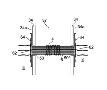
Figure 3 shows a cross-sectional side view of a first example aerosol source
configured in accordance with the present disclosure. Similarly to the Figure
2 aerosol
source, an annular reservoir 3 is provided, with two openings 50 in the inner
annular wall 34
arranged on opposite sides of the air flow channel 37. A wick or liquid
transport element 6 is
positioned across the channel 37 and has an associated vapour generating
element 4 in the
form of a heating coil wrapped around the liquid transport element 6. Leads
providing the
electrical supply for the heating coil are not depicted for simplicity. The
liquid transport
element 6, formed of porous material, has an elongate rod-like shape with the
heating coil
around its central part, between two end parts 62. Each end part 62 is
inserted into a
corresponding opening 50 in the reservoir wall so as to be exposed to liquid
held in the
reservoir 3. Liquid is absorbed by the end parts 62 and carried by wicking or
capillary action
through pores in the porous material of the wick to the heating coil 4 for
vaporisation.
Each end part 62 is provided with a flared portion 64, such that the wick ends
terminate in a flared shape, where the flared portion extends outwardly from
the sides of the
wick, reaching outwardly from the longitudinal axis of the elongate wick
around a hollow
space. In this example, the flared portion is arranged at right angles to the
wick axis, so the
hollow space is no longer bounded by wick material. The flared portion 64 is
located inside
the reservoir 3, and the right angle arises because the flared portion 64 is
in contact with the
inner surface 34a of the reservoir wall 34, over a region peripheral to the
opening 50. The
wick end is perpendicular to the wall 34 as it passes through the opening 50,
and the wall 34
8
9034147
Date Recue/Date Received 2023-12-22
is flat, so a right angle is required to form the contact between the flared
portion 64 and the
wall 34. Other configurations of wall, other angles of entry of the wick 6
into the reservoir 3,
and other relative positions of the wall 34 and the wick 6, will require other
angles (which
may be greater or less than a right angle) to achieve the contact. It is
likely that the angle will
be relatively large however, and in this example and similar examples, the
flared portion 64
can be considered as forming a flange around the end 62 of the wick 6.
Contact between the flared portion 64 and the inner surface 34a of the
reservoir wall
34 provides a sealing effect to inhibit leakage of liquid through the opening
50. Material of
the flared portion 64 extends across any gaps between the wick and the side
wall of the
opening 50, thereby at least partially blocking any fluid flow path that might
otherwise exist.
Some capillary sealing effect may arise from the contact between the flared
portion and the
inner surface 34a, owing to the wet environment inside the reservoir 3.
The flared portion 64 may be held in place against the inner wall surface 34a
by the
pressure of liquid in the reservoir 3, if the reservoir is a store of free
liquid, or by the
presence of any absorbent material placed inside the reservoir to hold the
liquid.
Alternatively, the flared portion 64 might be bonded to the inner surface 34a,
such as by
adhesive, by welding if the wall material and the wick material are suitable,
or by mechanical
means such as a clamp.
The wick 6 may be formed from fibres laid roughly parallel so as to extend
along the
length of the wick, and held in a bundle (such as being secured by the
windings of the
heating coil 4, or by other fastenings) or twisted or spun into a thread, yarn
or rope structure,
comprising one or more plies. In such a case, the flared portion 64 may be
formed on the
wick 6 by unravelling or untwisting the fibres (if necessary) over a short
distance at an end of
the length of material, and splaying the fibres out so they are separated from
their
neighbours and extend sideways from the length of the wick. The fibres can be
bent or
folded back until the appropriate angle required for contact with the inner
wall surface 34a of
the reservoir is attained. This process of forming the flared portion might be
performed after
the wick end is inserted into the opening in the reservoir wall, for example.
Other walls of the
reservoir may be added afterwards to complete the enclosing of the reservoir
volume, to
allow better access to the interior of the reservoir for this purpose.
Figure 3A shows an end view of a wick 6 with a flared end 64 formed in this
way. The
separated fibres (which may be individual, or collected in small groups) splay
out around the
end 62 of the wick, forming the shape of a flower or a sun with rays. The end
62 can absorb
liquid from the reservoir 3, and other liquid may be absorbed by the fibres of
flared portion 64
and carried to the end 62 by wicking. In this example, the flared portion 64
extends fully
around the wick 6, providing a sealing effect around the whole perimeter of
the opening 50.
9
9034147
Date Recue/Date Received 2023-12-22
In other examples, the flared portion 64 may be less extensive and extend over
a part or
parts of the opening's peripheral area only.
Figure 4 shows a cross-sectional side view of a further example aerosol source
configured in accordance with the present disclosure. This example is a
modified version of
that shown in Figure 3, so the description of like parts will not be repeated.
This example
differs from that of Figure 3 in that it additionally includes a compression
member 66
provided inside the reservoir 3 and positioned to press the flared portion 64
against the inner
wall surface 34a, thereby improving the contact between the two components and
enhancing
the sealing effect. The compression member 66 (shown slightly spaced apart
from the flared
portion 64 for clarity) exerts a compressive force against the flared portion
64 in the direction
of the arrows, being the longitudinal axial direction of the wick 6. A
compression member 66
may be used alone to keep the flared portion 64 in contact with the inner wall
surface, or
might be used together with any of the various contact arrangements noted
above for Figure
3.
Figure 4 shows the compression member 66 spaced outwardly from the edge of the
opening 50 so as not to impede access of liquid to the end part 62 of wick 6.
A closer
position, including at the opening's edge, might be used if preferred.
Figure 4A shows an end view of the flared portion 64 of the wick 6, comprising
splayed fibres as in Figure 3A, held by the compression member 66 pressed
against the
flared end 64. In this example, the compression member has the form of a ring
or short tube,
with a diameter greater than that of the opening so as to press the flared end
64 against the
inner surface 34a in a peripheral position at a distance from the edge of the
opening 62. The
ring shape provides a continuous line of contact between the flared portion 64
and the inner
surface 34a, providing a seal all around the opening 62. If the compression
member 66
comprises a tube of significant length, as in Figure 4, it may have apertures
provided in the
tube wall to allow freer movement of liquid within the reservoir and towards
the opening 50.
Alternatively, the tube might be formed from a mesh material with many pores
through which
liquid can flow. Otherwise, the compression member might comprise a number of
discrete
members that aid the contact at a number of locations over the area of the
flared portion.
The compression member or members may be held in place by being mounted on or
secured to any wall of the reservoir, for example.
The flared portion of the liquid transport element may be arranged in contact
with the
reservoir wall in a variety of ways to provide a sealing effect; the
arrangement is not limited
to the configuration of Figures 3 and 4. For example, the flared portion may
contact the
reservoir wall inside the opening. The opening in the reservoir wall is in
effect a hole through
the reservoir wall. The hole may be defined as a bore, where the bore itself
has a side wall
or walls that are also a surface of the reservoir wall.
9034147
Date Recue/Date Received 2023-12-22
Figure 5 shows a cross-sectional side view of an example aerosol source
configured
with the flared portion of the wick in contact with the wall of the bore or
opening. Aside from
differences in the association between the wick 6 and the wall 34 of the
reservoir 3, the
aerosol source is configured as in the previous examples so the description
will not be
repeated here.
In this example, the flared portion 64 at the end part 62 of the wick 6 is
located inside
the bore of the opening 50, rather than inside the main part of the reservoir
3 as in the
previous examples. A ring-shaped member (ring) 68 is also included; this has a
central hole
and an outer shape which need not be circular, but preferably matches, or is
similar to, the
.. shape and size of the opening 50 in the plane of the wall 34 so that the
ring 68 can be
closely fitted inside the bore of the opening 50. The wick 6 passes through
the central hole of
the ring 68 and is positioned so that the end part 62 is encompassed by the
ring 68. The
flared portion 64 of the wick 6 curves outwardly and back, towards the central
part of the
wick 6 where the heating coil 4 is accommodated, and over the ring 68 in its
position around
.. the wick end 62. The ring 68 is thus on an outer surface of the flared
portion 64. Thus, when
the wick 6 and the ring 68 are together inserted into the opening 50, the area
of the opening
is substantially filled, and the flared portion 64 is located between the
outer edge of the ring
68 and the surface of the wall that forms the bore of the opening 50. The end
surface of the
wick 6, being the surface of the end part 62 which is surrounded by the flared
portion 64 as it
.. extends outwardly, is substantially flush with the inner surface 34a of the
reservoir wall 34
(although it may be somewhat ahead or behind of this position depending on the
thickness
of the ring 68 and the position of the ring 68 relative to the depth of the
bore of the opening
50). The flared portion 64 is thus in contact with the wall of the reservoir 3
as it defines the
surface of the bore, around the filling of the opening by the wick end part
62, the ring 68 and
.. the flared portion 64 as it wraps over the ring 68, and a sealing effect is
provided to inhibit
fluid from being able to leave the reservoir 3 other than by absorption in the
end part 62 of
the wick 6. The flared portion 64 is compressed between the surface of the
wall defining the
bore and the ring 68, with the reservoir wall providing a compressive force
along a radial
direction of the wick, as shown by the arrows in the Figure. The ring 68 may
be made from a
.. rigid inflexible material, such as a rigid plastic or ceramic material, or
a non-corrosive metal,
for a maximum compressive effect, and shaped and sized so that its outer width
and
circumference matches that of the opening 50, and its inner width and
circumference
matches that of the wick 6. The wall 34 may be clamped onto, against or around
the ring 68
to enhance the seal. There is no requirement for the ring 68 to compress the
wick 6 at the
.. end part 62, such as could occur if the central hole of the ring is smaller
than the cross-
sectional size of the wick, because the end part 62 fills the opening 50 to
block the leakage
path. Compression of this sort may be included, however. Alternatively, the
ring 68 may be
11
9034147
Date Recue/Date Received 2023-12-22
formed from a resilient flexible material, such as rubber or a resilient
plastics material with
elastomeric properties, which may aid in its insertion into the opening 50.
Its shape can be
distorted or compressed during insertion, and it will then resume its required
shape after
insertion to maintain the contact between the flared portion 64 and the bore
wall. A
conventional 0-ring might be convenient for use as a ring, for example.
Figure 6 shows a cross-sectional view of a further example aerosol source, in
which
a ring is used in a different arrangement to that shown in Figure 5. Again, a
ring 68 is
provided which has a central hole and an outer size and shape which at least
approximately
matches that of the opening 50, and the ring 68 is disposed inside the opening
50, coaxially
therewith as before. In this case, however, the wick 6 is not inserted through
the central
opening of the ring 68. Instead, the ring 68 is inserted inside the flared
portion 64, holding it
open. The ring therefore rests against an inner surface of the flared portion
64. The flared
portion 64 faces forward towards the reservoir interior, and is not curved
back towards the
heating coil as in the Figure 5 arrangement. When the ring 68 and the wick 6
are inserted
into the opening 50, the flared portion is again pressed between the outside
of the ring 68
and the surface of the wall that defines the bore of the opening 50, providing
a sealing effect
as before since the area of the opening is filled by the flared portion 68,
the ring 68 and the
end part 62 of the wick 6. If the ring 68 is appropriately sized, and made
from a rigid or a
resilient material, it will exert a compressive force radially outwards with
respect to the wick 6
(shown by the arrows) to hold the flared portion 68 in close contact with the
bore wall. If the
ring 68 is rigid, the wall 34 may be clamped around it, as noted above for
Figure 5. The end
surface of the end part 62 of the wick 6 is aligned more closely with the
outer surface 34b of
the reservoir wall 34 (the surface bounding the air flow passage 37) than with
the inner
surface 34a, so the arrangement differs from the Figure 5 example in which the
end surface
of the wick is close to the inner surface 34a. Again, the exact position will
depend on the
thickness of the ring 68 and the positon of the ring 68 relative to the depth
of the bore of the
opening 50 and its position within the flared portion. The end surface of the
end part 62 is
exposed for absorption of the liquid from the reservoir, but the position of
this surface
requires the liquid to flow at least partly along the bore of the opening 50
to reach the wick
material. The liquid flows through the central opening in the ring 68 to reach
the end surface
of the end part 62.
Figure 7 shows a cross-sectional view of a further example aerosol source
having a
wick with a flared portion contacting the reservoir wall for sealing. As in
previous examples,
the end part 62 of a wick 6 is inserted into an opening 50 in the wall 34 of a
reservoir 3.
Contact is provided between a flared portion 34 of the end part 62 and the
inner surface of
the wall 34 defining the bore of the opening 50. The cross-section of the wick
6 thus fills the
opening 50, providing a seal and inhibiting leakage. The contact is achieved
by a plugging
12
9034147
Date Recue/Date Received 2023-12-22
element or plug 70 which is inserted into the end surface of the end portion
62 of the wick 6
so that the plug 70 penetrates the wick sufficiently so as to be also inside
the bore of the
opening 50. The plug 70 is aligned substantially parallel to the longitudinal
axis of the wick 6
in this example, and also parallel to the axis of the bore of the opening. The
penetration by
the plug 70 pushes the surrounding material of the wick 6 radially outwards
(to form the
flared portion if this has not already been formed by moulding or splaying of
fibres) and
against the surface of the bore wall. The wall 34 therefore provides a
compressive force,
shown by the arrows, radially inwardly with respect to the wick 6, around the
circumference
of the opening 50, to give the desired sealing effect. In this example, the
wick 6 is inserted
into the opening 50 but does not extend into the interior of the reservoir 3,
but in other
arrangements the wick 3 may reach into the reservoir somewhat. Also, the plug
70 reaches
into the wick 6 up to the plane of the outer surface 34b of the reservoir wall
34 in this
example.
Furthermore, the plug 70 in the Figure 7 example has the form of a tube or
pipe
(perhaps formed from a rigid or near-rigid material to provide the required
compression and
allow easy insertion into the wick 6). Liquid from the reservoir 3 can enter
the interior space
of the tube and flow along it to reach the material of the end part 62 of the
wick, so that liquid
is delivered directly into the core of the wick material for efficient
absorption and transport to
the heating coil 4. This can also help to compensate for any reduced
absorption at the end
surface of the flared portion 64 surrounding the tube 70, which is exposed to
the liquid in the
reservoir but may also be compressed such that its porosity is reduced.
Figure 8 shows a further example aerosol source in cross-section and similar
to the
Figure 7 example, but in which the plug 70 has the form of a solid rod rather
than a hollow
tube. There is hence no liquid penetration directly into the core of the wick,
but if the porosity
offered by the surrounding flared portion 64 is adequate for a required level
of absorption to
supply the heating element, this may be suitable. A solid plug may be
preferred if its non-
hollow structure makes insertion into the wick easier.
The Figure 7 and Figure 8 examples show openings 50 in the reservoir wall 34
which
have a non-uniform bore size. The side walls defining the bore are sloped or
curved so that
the bore is narrower at the outer surface 34b of the wall 34 than at the inner
surface 34a. In
other words, the bore of the opening tapers inwardly in the direction of the
liquid flow from
the reservoir 3 to the heating element 4. This may give a better match to the
shape of the
outer surface of the flared portion 64 as it is pushed outwardly by the plug
70, thereby
improving the contact and hence giving an enhanced seal. However, the bore
need not be
shaped in this way.
Similarly, the plug (whether hollow or solid) may have sloped sides to form a
tapered,
conical or frusto-conical profile such that the plug has a smaller width at
the end which is
13
9034147
Date Recue/Date Received 2023-12-22
inserted into the wick compared to the end at the reservoir interior. The
sloped sides may be
straight or curved. Such a shape may facilitate insertion of the plug into the
wick material,
Also, it can complement any sloped sides walls of the bore as described above,
to improve
the contact and enhance the seal.
Figure 9 shows a part of a cross-sectional view similar to the Figure 8
example, in
which the plug has a frusto-conical shape.
Figure 10 shows a related example aerosol source in cross-sectional view. As
with
the Figure 7 and 8 examples, a plugging element is inserted into the end of
the wick as it
extends into or through the opening in the reservoir wall. However, in this
case, the wick 6
has a cross-sectional size in the transverse (radial) direction which is
approximately the
same as the cross-sectional area of the opening, so the insertion of the
plugging element
does not cause the material at the end part of the wick to flare outwards
(i.e. to extend
further in the radial direction that the material in the central part of the
wick), because it is
constrained by the wall of the bore of the opening 70. Rather, the material is
compressed
against the bore wall only. This ensures contact between the wick 6 and bore
wall surface to
provide the desired sealing effect. The arrangement might be considered to
lack a flared
portion at the wick end, however, owing to the lack of outward extension of
the wick material.
The plug does create a hollow within the wick end, though, so the overall
shape and
functionality is similar to a more clearly flared arrangement.
As shown at the two ends of the wick 6 in Figure 10, the plug 70 may comprise
a
tube or a solid rod as in the Figure 7 and Figure 8 examples. A tube might be
preferred as
enabling better absorption of liquid into the wick by exposing a larger amount
of wick
material to the liquid, since the straight sided end portions of the wick
offer a smaller end
surface of wick material to the reservoir interior compared to the Figures 7
and 8 examples
where the wick material has space to move sideways when the plug 70 is
inserted.
The various examples herein are not intended to be limiting, and other
configurations of a flared-end wick in contact with the area at, in or around
a reservoir
opening to provide a seal can be contemplated.
For example, the reservoir need not be an annular shape surrounding a central
airflow passage as in the Figures 3 to 10 examples, with two diametrically
opposed openings
receiving opposite ends of the same wick. Rather, the reservoir may be any
convenient
shape or size, and may include a different number of openings for receiving
one or more
ends of one or more wicks. On a related point, the wick need not have two
liquid-receiving
ends as in the illustrated examples, but may have a single-ended shape with
one end
associated with a reservoir opening and another portion associated with the
vapour
generating element. For a wick with more than one end, one or more ends may be
provided
with a flared portion for sealing contact as described herein, and two ends
may use the
14
9034147
Date Recue/Date Received 2023-12-22
same or different arrangements to effect the contact. A wick with two ends may
be linear as
in the illustrated examples, but may be bent or curved such as forming a U-
shape.
The illustrated examples include a vapour provision element in the form of a
resistive
wire heating coil, but any configuration of vapour provision element may be
used, including
other shapes of resistive wire, other configurations of resistive metal such
as embedded
heater or a deposited metal layer or trace, electrical heating elements
configured for
inductive heating, and vapour generating elements that operate without heat,
such as
vibrating perforated plates and membranes.
A variety of porous materials may be used for a wick or liquid transport
element
according to the present disclosure. The material should have an appropriate
porosity to
provide the required wicking rate (liquid delivery rate) for the source liquid
or liquids with
which it is envisaged to be used. In some cases a degree of compressibility
will enhance the
sealing effect where the contact is effected with the aid of a pressing or
pushing component
(such as the compression members, rings and plugs described above). In these
cases the
material may therefore be compliant, soft, flexible and/or non-rigid. The wick
may be formed
from fibres, which are bundled, or twisted or spun into one or more threads,
yarns or ropes,
which may then themselves be bundled. Also, fibres can be formed into woven
and non-
woven fabric that can be rolled, twisted or otherwise formed into a wick
shape. The fibre may
comprise natural materials such as cotton, wool, cellulose or linen, or
artificial materials such
as various polymers and plastics. Ceramics and glass fibres may also be used.
For a fibre-
based wick, the flared portion may be form by unravelling and/or splaying the
fibres as
described with regard to Figures 3 and 3A. Alternatively, the wick may
comprise a foamed or
sponge material (include natural and man-made sponges and foamed ceramics, for
example). If the material is sufficiently pliable, the flared portion may form
during installation
of the wick, such as insertion of a plug into the wick end as in the Figures
7, 8 and 9
examples. Otherwise, the flared portion may be specifically formed integrally
with the shape
of the rest of the wick by a moulding, machining or other shaping process. The
flared portion
may be pliable so as to be bent or folded into a required position, such as
being wrapped
over a ring in the Figure 5 example, or the flared portion may be formed to
already have its
required final "in use" shape.
In conclusion, in order to address various issues and advance the art, this
disclosure
shows by way of illustration various embodiments in which the claimed
invention(s) may be
practiced. The advantages and features of the disclosure are of a
representative sample of
embodiments only, and are not exhaustive and/or exclusive. They are presented
only to
assist in understanding and to teach the claimed invention(s). It is to be
understood that
advantages, embodiments, examples, functions, features, structures, and/or
other aspects of
the disclosure are not to be considered limitations on the disclosure as
defined by the claims
9034147
Date Recue/Date Received 2023-12-22
or limitations on equivalents to the claims, and that other embodiments may be
utilised and
modifications may be made without departing from the scope of the claims.
Various
embodiments may suitably comprise, consist of, or consist essentially of,
various
combinations of the disclosed elements, components, features, parts, steps,
means, etc.
other than those specifically described herein. The disclosure may include
other inventions
not presently claimed, but which may be claimed in future.
16
9034147
Date Recue/Date Received 2023-12-22