Note: Descriptions are shown in the official language in which they were submitted.
WO 2023/002420
PCT/IB2022/056729
- 1 -
A Wave Generating Installation and Method
FIELD OF INVENTION
This invention relates broadly to artificial wave generation and specifically
to a
wave generating installation and method (e.g., for use in water sports or
recreation).
BACKGROUND OF INVENTION
The Applicant is aware of an existing installation by Wave Gardens (a Spanish
company) which has experimented with artificial waves using a rotating
platform
(generally referred to as a carousel) with at least one ramp or vane to act as
a wave
former. The installation is placed in a large body of water (like a lake or
pool) and the
carousel rotates, driving the wave former through the water. As the wave
former slews
through the water, it creates a wave (with a snowplough-like effect).
A drawback of this installation is that it would create significant turbulence
and
currents surrounding the carousel in the direction in which the carousel
rotates,
eventually causing the surrounding water to start rotating too, like a large
whirlpool. As
the water rotates, the relative speed between the wave former and the water
decreases
(and approaches zero as the whirlpool speed approaches the carousel speed)
which
decreases the wave creation action. This could perhaps be countered by
providing
large pumps or water jets to counteract the whirlpool effect, but this would
increase
cost and complexity of the installation.
CA 03226502 2024- 1-22
WO 2023/002420
PCT/IB2022/056729
- 2 -
The Applicant desires a wave generating installation which overcomes or
ameliorates this drawback.
SUMMARY OF INVENTION
Accordingly, the invention provides a wave generating installation configured
to
generate a wave in water, the installation including:
a carousel configured to rotate about an upright axis of rotation;
at least one wave former fixed relative to the carousel and therefore
configured to rotate with the carousel, wherein the wave former is configured
to
lo form an incoming stream of water into a standing wave;
a water outlet spaced away from the wave former, the water outlet being
configured to direct a stream of water over part of the carousel towards the
wave
former; and
at least one water pump connected via a water conduit to the water outlet,
thereby to produce the stream of water,
wherein the installation is configured to direct the stream of water over the
rotating carousel towards the wave former, thereby to generate the wave which
is a standing wave relative to the carousel but which rotates with the
carousel.
The term "standing wave" in the context of this specification may include a
hydraulic jump wave (as is more conventional) and/or may include sheet-flow of
water
over a formation to create a mound with a wave-like appearance (even though it
might
not conform to a conventional definition of "wave" or "standing wave").
The water outlet may be configured to rotate with the carousel, such that the
stream of water remains directed at the wave former while the carousel
rotates.
CA 03226502 2024- 1-22
WO 2023/002420
PCT/IB2022/056729
- 3 -
The wave former may be provided at a periphery of the carousel. The water
outlet may be provided at a centre of the carousel inwardly of the wave former
and is
configured to direct the stream of water outwardly towards the wave former.
Water flow may be directed from the carousel centre outwards, or may be
directed backwards relative to the carousel direction of rotation, or may be
directed
from the carousel perimeter inwards, towards the wave former.
The water outlet may be elongate and may be provided on the carousel between
a centre and a periphery thereof. The wave former may also be provided on the
carousel between a centre and a periphery thereof, the water outlet being
configured
to direct the stream of water circumferentially towards the wave former.
The installation may include plural water outlets and plural wave formers
spaced
circumferentially apart. The water outlets may be configured to direct
respective water
streams to the wave formers. The plural water outlets and plural wave formers
may
be equiangularly spaced apart.
The water outlet may be configured to create sheet flow of water over a water
flow zone of the carousel arranged between the water outlet and the wave
former.
Water flow may provide adequate energy to counteract wave stall and to off-set
the whirlpool effect in the pool, and the water flow may be blended with pool
water
crossing the wave former, or water crossing over the wave former may be
substantially
composed of water from the nozzle.
The carousel may define at least one raised zone rotationally adjacent to the
water flow zone, the water flow zone being in the form of a trough being
depressed or
lowered compared to the adjacent raised zone. The raised zone may be a water
displacement zone and may be considered as a "travelling reef".
CA 03226502 2024- 1-22
WO 2023/002420
PCT/IB2022/056729
- 4 -
The water outlet may emit water around most or all of a rotational area of the
carousel, but the stream of water directed towards the wave former may include
more
water than water emissions not directed to the wave former, e.g., more water
per unit
area. The water not directed towards the wave former may be considered spill
water
and may also counter-act the whirlpool effect.
The stream of water may have a positive flow rate and a raised pressure head
upon being emitted from the water outlet. Raised pressure head may imply
pressurised or pumped. The carousel may be configured to energise the stream
of
water additionally by downward gravitational flow and/or by Coriolis effect,
but pumped
flow may create the raised water level and energy potential for gravity flow.
The wave generating installation may include a hub at a centre of the
carousel.
The hub may be integrated with or fixed to the carousel, the hub thereby being
configured to rotate with the carousel. The carousel may be displaceable
relative to
the hub and the hub may be fixed, the carousel thus being configured to rotate
around
the hub. The hub may accommodate the water outlet. Alternatively, the hub may
be
void of any carousel structure and may therefore be an inner part of the pool
surrounded by the ring-shaped carousel.
The water outlet may be on or in the carousel.
The carousel may be circular or annular (or approximately so, like oval). The
carousel may be of rigid and/or flexible material. The carousel may include
bladder
structures. The carousel may include an underlying support structure over
which a
skin or membrane is supported.
The wave generating installation may include a pool housing a body of water.
The carousel may be provided in the pool. The stream of water may be drawn
from
CA 03226502 2024- 1-22
WO 2023/002420
PCT/IB2022/056729
- 5 -
the body of water and tail water may return to the body of water, in a
circular and
repeating loop. The carousel may be partially or fully immersed in the body of
water.
The wave generating installation may include at least one hyperbaric seal
provided between the carousel and the body of water. One or more air chambers
may
be provided beneath the carousel, separated from the body of water by the
hyperbaric
seal. The air chambers may be pressurised, e.g., to atmospheric pressure
relative to
the water depth at which the seal is located.
The pump (independent of the carousel or integrated within the carousel) may
include vanes (or similar structures like scoops or fins) attached to the
carousel, such
that rotation of the carousel in or on the body of water causes a pumping
action. The
vanes may be separate from the wave former. The vanes may be attached to a
side
or underside of the carousel. The vanes may be considered rotary vanes because
they rotate with the carousel. The installation may include complemental
static vanes.
The static vanes may be mounted to the pool or other support structure, e.g.,
adjacent
to or opposed to the rotary vanes.
This may resemble a Jonval turbine
(httbs://en.wiKipedia,oralwiKi/Jonval turbine) operated either normally or in
reverse.
This pumping action may be derived from the rotation of the carousel but be
separate from the wave making action. In other words, different structures may
be
responsible for wave making (the wave former) and pumping (the vanes).
However,
both structures may derive motive power from the same source, that is,
rotation of the
carousel.
The water conduit may be, or may include, spiral scroll water supply
structures
provided beneath or in the carousel. The water supply structures may conduct
water
from the vanes, where it is pumped, to the water outlet, where it is emitted.
CA 03226502 2024- 1-22
WO 2023/002420
PCT/IB2022/056729
- 6 -
The installation may include a motor configured to rotate the carousel. The
installation may include associated parts, like bearings, axles, or gearboxes,
etc. to
couple the motor to the carousel. The motor may be an electric motor.
The pump may be a standalone device, like an electrically powered pump. The
pump may be an axial flow or centrifugal pump. The water conduit may then be a
pipe
or duct between the pump and the water outlet.
The wave former may continuously channel head flow water lifting and shaping
it
into the wave. The wave may be orientated towards, or away from, or radially
of an
inside of the carousel, resulting in inward (concave) or outward (convex) wave
shapes.
The wave former for centre head-flow discharge versions may be orientated at
an
acute angle, relative to a carousel direction of rotation. The wave former may
be fixed
or deformable, hard or soft.
The water outlet may be configured to direct the stream of water in a
direction
which, at least partially, opposes a direction of rotation of the carousel.
This may
counter a whirlpool effect.
The generated wave may be used for water sports or recreation, like surfing,
boarding, paddling, swimming, playing, etc.
Centrifugal force above 20% may be undesirable for surfing, so an 8 m radius
carousel should have an outer velocity below 4 m/s (4.7 rpm), where a 50 metre
radius
carousel may have an outer velocity up to 10 m/s (1,9rpm). It follows that
velocity may
be a limitation to wave size and therefore bigger carousels may have bigger
waves
due to their tolerable speed range. Water flow volumes may be determined by a
flow-
rate where the velocity of water flow may be higher than the carousel
perimeter
velocity. Each wave former may easily manage a flow rate of 10 cubic metres
per
second.
CA 03226502 2024- 1-22
WO 2023/002420
PCT/IB2022/056729
- 7 -
The invention extends to a method of generating a wave in water, the method
including:
rotating a carousel about an upright axis of rotation;
providing at least one wave former fixed relative to the carousel and
therefore configured to rotate with the carousel;
pumping, with at least one water pump via a water conduit, water to the
water outlet, thereby to produce the stream of water;
directing the stream of water from the water outlet, which is spaced away
from the wave former, over part of the carousel towards the wave former; and
forming, by the wave former, the stream of water into a standing wave
relative to the carousel but which rotates with the carousel.
BRIEF DESCRIPTION OF DRAWINGS
The invention will now be further described, by way of example, with reference
to
the accompanying diagrammatic drawings.
In the drawings:
FIG. 1
shows a schematic plan view of a first embodiment of a wave generating
installation, in accordance with the invention;
FIG. 2
shows a schematic cross-sectional view of the wave generating
installation of FIG. 1;
FIG. 3
shows a schematic plan view of the wave generating installation of FIG.
1 including a pool;
FIG. 4 shows a
schematic cross-sectional view of the wave generating
installation of FIG. 3;
FIG. 5
shows a schematic plan view of a second embodiment of a wave
generating installation, in accordance with the invention;
CA 03226502 2024- 1-22
WO 2023/002420
PCT/IB2022/056729
- 8 -
FIG. 6 shows a schematic plan view of a third embodiment of a
wave generating
installation, developed from that of FIG. 5;
FIG. 7 shows a schematic cross-sectional view of another
embodiment of a
wave generating installation, developed from that of FIG. 2;
FIG. 8 shows a schematic cross-sectional view of another embodiment of a
wave generating installation, developed from that of FIG. 2;
FIG. 9 shows a schematic plan view of another embodiment of a
wave
generating installation, in accordance with the invention;
FIGS 10-12 show schematic cross-sectional views of further embodiments of wave
generating installations, in accordance with the invention;
FIG. 13 shows a schematic cross-sectional view of another
embodiment of a
wave generating installation, in accordance with the invention;
FIG. 14 shows a schematic plan view of part of the installation
of FIG. 13; and
FIG. 15 shows a schematic plan view of another embodiment of a
wave
generating installation, in accordance with the invention.
DETAILED DESCRIPTION OF EXAMPLE EMBODIMENT
The following description of an example embodiment of the invention is
provided
as an enabling teaching of the invention. Those skilled in the relevant art
will recognise
that changes can be made to the example embodiment described, while still
attaining
the beneficial results of the present invention. It will also be apparent that
some of the
desired benefits of the present invention can be attained by selecting some of
the
features of the example embodiment without utilising other features.
Accordingly,
those skilled in the art will recognise that modifications and adaptations to
the example
embodiment are possible and can even be desirable in certain circumstances and
are
a part of the present invention. Thus, the following description of the
example
embodiment is provided as illustrative of the principles of the present
invention and not
a limitation thereof.
CA 03226502 2024- 1-22
WO 2023/002420
PCT/IB2022/056729
- 9 -
FIG. 1 illustrates a basic wave generating installation 100 in accordance with
the
invention. The installation has a circular carousel 102 with a central hub 104
and a
peripherally extending outer edge 106. The carousel 102 is mounted to rotate
about a
central upright axis and may be driven by a motor or other drive means (not
illustrated).
The carousel 102 is provided in a body of water (see, e.g., FIG. 3).
A water outlet 110 is provided at, or underneath, the hub 104. The water
outlet
110 is not specifically illustrated in FIG. 1 (but see description and FIGS
below). The
water outlet 110 is configured to emit a stream of water 112 over part of the
carousel
110 designated as a water flow zone 114. The presence of the water outlet 110
is an
important part of this embodiment and may serve as one of the features to
distinguish
this embodiment inventively from prior art installations. The stream of water
112 over
the water flow zone 114 may be smooth or coherent flow, like sheet flow, or
even
laminar flow.
The carousel 102 has a wave former 120 which, in this embodiment is elongate
and extends tangentially along the outer edge of the carousel 102. The wave
former
120 is in the form of a ramp or curved fin. The water outlet 110 is configured
to direct
the stream of water 112 towards the wave former 120 which, in turn, redirects
flow to
convert the stream of water 112 into a wave (or wave-like formation). It will
thus be
noted that it is the action of the stream of water 112 interacting with the
wave former
120 that creates the wave, and not (or at least, not primarily) the action of
the carousel
102 rotating in a larger body of water ¨ as is the case with prior art
installations ¨ which
creates the wave.
It may be noted that the water outlet 110 is not radially aligned with the
wave
former 120 but is rotationally offset. This compensates for the rotation of
the carousel
102 which may cause the stream of water 112 to curve at it radiates outwardly
¨ as
noted in the FIG. 1 having curved lines illustrating the stream of water 112.
This may
be due to inertia of the stream of water 112 on the rotating carousel 102
(e.g., the
Coriolis effect).
CA 03226502 2024- 1-22
WO 2023/002420
PCT/IB2022/056729
- 10 -
Depending on the configuration of the water source 110 and/or the hub 104,
there
may be spill water 113 emitted from the water source 110 and/or the hub 104
not
directed towards the wave former 120. This may be the case, for example, when
the
hub 104 includes a 360' circular nozzle configured to discharge water 360'
around
and the water source 110 is, or includes, a rotating aperture to direct the
water towards
the wave former 120 and occludes but does not entirely block it in the
remaining arc.
Tail water 122 from the wave is directed or dissipated outwardly from the
outer
edge 106 of the carousel 102 and returns to the body of water. As this tail
water 122
is dissipative, it does not contribute significantly to any whirlpool effect
within the body
of water. Further, as the wave generating action is as a result of the stream
of water
112 interacting with the wave former 120 and not as a result of the wave
former
slewing/ploughing through the body of water, the wave creation action does
also not
contribute significantly towards any whirlpool effect.
The carousel 102 itself may be streamlined for gliding through surrounding
water
and not itself displacing significant water through rotation. The wave former
120 may
displace the water (specifically, the stream of water 112) which may be offset
the
incoming water sourced by the water outlet 110.
FIG. 2 shows a cross-sectional view of the installation 100. As mentioned
above,
the water outlet 110 may not always be radially aligned with the wave former
120 ¨ this
FIG shows them as being aligned for the sake of illustration, but this could
be an offset
sectional view.
It is more clearly illustrated that the stream of water 112 is emitted from
the water
source 110 and directed over the water flow zone 114 of the carousel 102
towards the
wave former 120. The wave former 120, in turn, converts the stream of water
112 into
a wave 124. The characteristics of the wave 124 (e.g., large, barrel, curl,
etc.) may
largely be dictated by the shape of the wave former 120 but also by the
characteristics
CA 03226502 2024- 1-22
WO 2023/002420
PC T/IB2022/056729
- 11 -
of the stream of water 112. The wave 124 dissipates as the tail water 122
returns to
the body of water.
The wave 124 is a standing wave relative to the carousel 102. In other words,
with the carousel 102 as a point of reference, the wave 124 will be somewhat
static in
its overall shape. As the carousel 102 rotates in use, the wave 124 can
therefore be
described as a standing wave rotating with a periphery of the carousel 102.
This may
be beneficial in that it has the benefits of a standing wave (e.g., being able
to support
a surfboard or wave board in a reliable way) while still having the effect of
moving
through the water.
FIG. 3 illustrates the carousel 102 in a body of water 130 provided by a pool
132,
lake, or similar structure (whether artificial or natural). If the size of the
pool 132 needs
to be minimised, it can be configured to be round or oval and somewhat larger,
but not
significantly so, than the carousel 102 (as in FIG. 3). However, various
different
creative embodiments are practicable (see below).
FIG. 4 shows a more complete illustration of the wave generating installation
100.
A water pump 140 is provided which, in this embodiment, is underneath (at a
lower
level than) the carousel 102; the pump 140 is either in the body of water 130
in the
pool 132 or in fluidic communication therewith. Although various pump
embodiments
may be practicable, this pump 140 is an electrically powered axial flow pump.
A water
conduit in the form of a large capacity pipe or duct 142 is provided to direct
pumped
water from the pump 140 towards the hub 104.
The pipe 142 leads into a cavity 143 beneath the hub 104 which is largely
hollow.
The hub 104 defines a traveling aperture 144 which rotates together with the
carousel
102 thereby to maintain a fixed angular alignment relative to the carousel 102
(and
hence relative to the wave former 120. The aperture 144 serves as the water
outlet
110 for directing the stream of water 112 towards the wave former 120.
Alternatively,
a fixed-in-place hub island with its outer edge as a uniform annular upper-lip
to nozzle
CA 03226502 2024- 1-22
WO 2023/002420
PCT/IB2022/056729
- 12 -
while the lower lip/floor is the moving carousel surface, having bathymetry
with shallow
regions either side of a deeper opening which defines the main water flow
nozzle.
In this embodiment, the hub 104 actually provides a 3600 water discharge. A
more substantial volume of water is channelled through the aperture 144
serving as
the water outlet 110, but spill water 113 is channelled out of a narrow gap
146 between
the hub 104 and the carousel 102 in other areas not aligned with the wave
former 120.
This spill water 113 may have a lower head or a lower volume per unit width
compared
to the stream of water 112, thus not requiring significantly more pumping
capacity.
The installation 100 may include a mechanical motor (not illustrated) to
rotate the
carousel 102 at a desired speed. The output of the motor and/or the pump 140
may
be customisable to control operational characteristics, e.g., wave generating
characteristics, of the installation 100.
While the carousel 102 may be configured to be supported on top of the body of
water 130, in this example, it is not, instead having its underside sealed off
from the
body of water 130. More specifically, an annular contactless hypobaric seal
assembly
149 is provided around, e.g., depending downwardly from, the periphery of the
carousel 102 to interact with a complemental upstanding formation 149 (like a
fin or
wall) provided in the pool 132 in which the carousel 102 is located. This may
have
various advantages including lowering a rotational drag of the carousel 102,
reducing
any whirlpooling effect in the body of water 130, etc. With such a
configuration, the
carousel 102 may be a relatively thin or light structure which need not
necessarily even
have a bottom wall.
FIG. 5 illustrates another embodiment of a wave generating installation 200 in
accordance with the invention. The same or similar numerals to those in other
FIGS
may refer to the same or similar parts. This installation 200 employs the same
principle
as the previous installation 100, but has a different implementation.
CA 03226502 2024- 1-22
WO 2023/002420
PCT/IB2022/056729
- 13 -
More specifically, a water outlet 210 and wave former 220 extend somewhat
radially (or obliquely) and are circumferentially aligned and spaced apart.
The water
outlet 210 is elongate and arcuate and configured to emit a stream of water
212 in a
generally circumferential direction, across a water flow zone 214, opposite to
a
direction of rotation 208 of the carousel 202. The water outlet 210 may be in
the form
of an elongate slot or nozzle, outputting the stream of water 212 generally as
a sheet
which is maintained across the water flow zone 214. The direction of the
stream of
water 212 may oppose the direction of rotation 208, which may enhance wave
generating characteristics or reduce whirlpooling in the body of water 130,
etc.
The wave former 220 is orientated somewhere between radial and
circumferential and can be characterised as oblique or rearwardly swept. Its
angle
relative to a radius may be varied to influence characteristics of a wave
which it
produces. Tail water 222 again runs off from behind the wave former 220.
FIG. 6 illustrates a developed version 201 of the wave generating installation
200
which has three equiangularly spaced sets of water outlets 210 and wave
formers 220.
The installation 201 with plural sets of water outlets 210 and wave formers
220 may
be beneficial in being able to produce more waves (three times as many, in
this
example) for the same carousel footprint.
Applying this logic to the installation 100 of FIGS 1-4, there could be plural
water
outlets 110 directed respectively towards plural wave formers 120 (not
illustrated). In
fact, plural water outlet-wave former combinations may even be desired
because, if
rotationally symmetrical, this may provide better centricity of the carousel
102 for
smoother rotation or lower rotational energy input.
FIGS 7-8 show different wave former configurations. In FIG. 7, a wave
generating installation 230 lacks the hub 104 present in the earlier
installation 100.
This lack of a hub may provide for a water outlet 231 providing a stream of
water 232
having different characteristics. For example, the water outlet 231 may be
provided
CA 03226502 2024- 1-22
WO 2023/002420
PCT/IB2022/056729
- 14 -
from a raised head or pressurised source of water to swell onto the water flow
zone
114 of the carousel 102, instead of being jetted or jettisoned via a nozzle.
This may
allow the stream of water 232 to be deeper and/or slower which may provide a
wave
234 with different characteristics.
In FIG. 8, an installation 240 is still hubless, but also has a wave former
242
having reduced height compared to the wave former 120 of previous
installations 100,
230. A wave 244 may be formed by a hydraulic jump having more open water flow.
The wave former 242 may work with largely stationary water in the body of
water 130
behind providing a wave-forming bathymetry. The wave 244 may have different
characteristics (e.g., height, curl, barrel) from the other waves 124, 234
being formed
by a slightly different hydraulic jump interaction.
FIG. 9 illustrates a wave generating installation 250 with the wave formers
120 of
the installation 100 of FIG. 1, but having three such wave formers 120 spaced
1200
apart around the carousel 102. Notably, however, there are more distinct water
zones
254, 256. A water flow zone 254 arranged between the water outlet 110 and the
wave
former 120 is deeper, like a trough. However, water displacement zones 256 are
circumferentially spaced between the respective water flow zones 254 and are
shallower, that is, raised relative to the water flow zones 254.
Conceptually, the water displacement zones 256 may be considered reef zones
or travelling reefs, in use. The water displacing zones 256 are configured to
displace
water flow by having only a very shallow/thin flow over these zones 256 and a
relatively
low flow volume compared to the deeper, adjacent water flow zones 254. The
water
displacement zones 256, together with the wave formers 120, may also
substantially
bar pool water 130 from flowing into the advancing water flow zones 254. The
water
displacing zones 256 may be back-swept in plan view to deflect unwanted water
away
from the water flow zones 254, and an inside boundary 258 may work as weir
containment at leading and trailing boundaries of openings of the water
outlets 110
where deeper water flows out into the water flow zones 254.
CA 03226502 2024- 1-22
WO 2023/002420
PCT/IB2022/056729
- 15 -
FIGS 10-12 show various installations 250, 260, 270 with carousel
configurations
providing hyperbaric chambers which may allow for hyperbaric or barometric
seals. In
FIG. 10, a carousel 252 is configured to have a hollow cavity 254 underneath.
The
cavity 254 is pressurised above atmospheric pressure in proportion to the
water depth
within the seal. An outer air trap water seal (or hyperbaric seal) 256 is
provided around
a periphery of the carousel 252. The pressurised, hollow cavity 254 displaces
pool
water 130, thereby creating a dry space optionally within which to house
mechanical
and structural components of the carousel 252 such as but not limited to drive
train
and slewing carriage.
The cavity 254 also reduces water drag during rotation of the carousel 252 and
reduces load on the carousel undercarriage. To overcome excessive lift, the
seal 256
and the cavity 254 create a water level at a depth where consequent air
pressure is
balanced against the overall weight of the carousel 252 in live loads such as
possible
suction caused by water flow.
FIG. 11 illustrates an installation 260 with an annular carousel 262 having a
differently shaped cavity 264 and an inner pool or water area 268. A pair of
seals 256,
266, namely the outer seal 256 and an inner seal 266 may be provided. In FIG.
12,
the installation 270 also has an annular carousel 272 but it has an overhang
and
therefore a much smaller cavity 274 but operates on the same principle.
The installation 250, 260, 270 of FIGS 10-12 may provide that the carousel
252,
262, 272 remains as neutrally buoyant as possible, and may take advantage of
the
lifting force provided by the compressed air where this is structurally and
mechanically
beneficial. Features of the cavity 254, 264, 274 may include means for access
such as
hatch access from directly above via vertical air lock, or underpass access
below the
pool via air lock. Access may alternatively require that air pressure is
released prior to
entering from above or below. The hyperbaric system may include a labyrinth
contactless seal or may have slewing seals similar to those found on bearing
races.
CA 03226502 2024- 1-22
WO 2023/002420
PCT/IB2022/056729
- 16 -
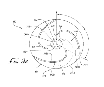
FIG. 13 illustrates a more developed version of a wave generating installation
300 in accordance with the invention. While having a separate electrically
powered
water pump is an option, this installation 300 employs carousel rotation to
create
pumping action, as will become apparent.
The installation 300 has a generally circular or annular carousel 302 (similar
in
shape to those of previous embodiments). More specifically, the carousel 302
comprises a bladder-like outer membrane tensile structure on a marine grade
GMS
carousel wheel supporting frame.
A hub assembly 304 supports the carousel 302 and permits it to rotate about an
upright axis of rotation. Drive means (not illustrated) to rotate the carousel
302 may
include a pin-wheel gear to mounted to outer compression ring or inner tension
ring
hub. The hub assembly 304 is mounted to a concrete support structure 336. The
hub
assembly 304 comprises a slewing hub with a bearing and seal system.
The carousel 302 is accommodated in a body of water 130 and a small central
pool 358 is provided above the hub assembly 304. A wave former 320 is provided
at
a periphery of the carousel 302. The wave former 320 is in the form of a mound
presenting a concave surface to a stream of water 312 thereby to create a wave
324.
Tail water 322 runs off from the wave 324 to return to the body of water 130.
As with previous embodiments, a water outlet 310 in the form of a discharge
nozzle emits the stream of water 312 as sheet flow over a water flow zone 314
of the
carousel 302. This water flow zone 314 is depressed relative to an opposite
water
displacing zone 315 above which spill water 313 is permitted to stream. The
water
displacing zone 315 is raised and may be embodied by a soft foam or water-
filled
membrane bladder having a back-swept spiral plan form.
A water level 332 of the body of water 130 is configured to overflow into
weirs
330. The weirs 330 may cover a majority (more than 50%) of a perimeter of the
pool.
CA 03226502 2024- 1-22
WO 2023/002420
PC T/IB2022/056729
- 17 -
The weirs 330 may be covered with protective grates. Surrounding the pool may
be
paving, a deck 360, or the like, for cosmetic or recreational purposes. A
recirculating
pump 334 may be integrated with the weir 330 to drop the weir water level
lower than
the pool water allowing small waves in the pool to collapse into the weir, to
permit the
pool water surface to remain relatively calm.
Important to this embodiment, and referring now also to FIG. 14, the carousel
302
has a plurality of vanes 344 arranged at a periphery thereof. The presence of
the
vanes 344 permit the carousel 302 to act also as a water pump (e.g., similar
to a Jonval
turbine in reverse). Water pumped from the vanes 344 is channelled via
conduits in
the form of inward spiral scroll water supply structures 346 which may be
rigid or
flexible membrane bladder structures. These water supply structures 346 feed
the
pumped water to the water outlet 310 which emits the water as the stream of
water
312 across the water flow zone 314.
The installation 300 may include one or more co-axial corresponding stator
vane
arrays which may be fixed to a stator vane support structure 348, and
additionally or
alternatively may have one or more counter-rotating co-axial impeller arrays
mounted
on the carousel 302 or on the ground structure. Said vane arrays may be
orientated
for axial or for radial pumping and are located co-axially anywhere on, or
within, or in
proximity to, the carousel 302.
The carousel 302 includes a rail and bearing assembly 342 to help support and
guide its rotation as well as an air trap water seal 340. This provides a
substantially
dry space 354 beneath the carousel 302 for mechanical equipment and
maintenance
access, maintained by air pressure and partitioned by coffer dam walls.
Accordingly,
the installation 300 may be considered a hyperbaric carousel (like those in
FIGS 10-
12). A cistern 356 may collect and hold pool water when air pressure is lost
causing
water to drain through the air seal 342.
CA 03226502 2024- 1-22
WO 2023/002420
PCT/IB2022/056729
- 18 -
The installation 300 may have rigid, hollow structures 345 to carry the wave
formers 320 and to form a diverging component of contactless venturi seal,
combined
with diffuser vanes.
FIG. 15 illustrates a further wave generating installation 370 in accordance
with
the invention. The installation 370 comprises a rotary carousel 372 having a
bladder-
like outer membrane tensile structure, bicycle wheel type supporting frame,
and means
to force rotation which may include a pin-wheel gear to the outer compression
ring or
inner tension ring hub. Wave formers 390 are at a periphery of the carousel
372.
The carousel 382 may have the same vane and water conduit structure 344, 346
(in FIG. 14) as that of the installation 300.
Water flow zones 384 having sheet flow water are ahead of traveling wave
formers 390 and water displacement zones 385 in the form of "travelling reefs"
are
provided in between. The water displacement zones 385 may be soft foam or
water-
filled membrane bladders having a back-swept spiral plan form and being raised
to
form a blockage to water-flow which funnels head-water towards the water flow
zone
384 and may direct pool water away from water flow zone 384.
The installation 370 has a weir perimeter rim-flow water discharge 380 which
may
be to a majority (more than 50%) of the pool perimeter. A stairwell 387
connects an
airlock with a pool deck 388 and surrounding area. A moat structure 389
substantially
blocks water passage and lazy-river from forming in ring-shaped pools.
The Applicant believes that the invention as exemplified provides an
installation
which can create usable artificial waves. Advantages include:
A standing wave (or pseudo-standing wave) is provided, but this wave
moves with the carousel.
CA 03226502 2024- 1-22
WO 2023/002420
PCT/IB2022/056729
- 19 -
The wave former does not create a wave by ploughing through the pool
water. This reduces whirlpooling.
The water outlet provides the water for the wave, meaning the wave-
generating water supply can be separately controlled.
Characteristics (length, inclination, curvature, height, etc.) of the wave
former can be configured which will not impact on other aspects (e.g.,
carousel
rotation) of the installation.
In one embodiment, the pumping action for the water outlet and can be
provided by the rotation of the carousel by adding a vane assembly.
Various hyperbaric carousel configurations are available, for reduced drag
and lower whirlpooling.
CA 03226502 2024- 1-22