Note: Descriptions are shown in the official language in which they were submitted.
WO 2023/009190
PCT/US2022/025996
1
LOW REFLECTANCE REMOVABLE LENS STACK
CROSS-REFERENCE TO RELATED APPLICATIONS
[0001] Not Applicable
STATEMENT RE: FEDERALLY SPONSORED RESEARCH/DEVELOPMENT
[0002] Not Applicable
BACKGROUND
[0003] In various environments where one uses protective eyewear such as
goggles,
visors, and face shields, it is important to maintain visibility as debris
accumulates on
the eyewear. For example, participants in off-road sports like motocross
racing need
to maintain visibility of the course as mud, bugs, and other debris accumulate
on their
goggles or helmet visor. Similarly, in an operating room environment, splatter
can
impair the view of surgeons or other operating personnel during a procedure.
In
response to these needs, tearoff films are commonly employed, either
individually or
in laminated stacks, which are applied to the goggle lens, visor, or face
shield. As
debris accumulates on the outermost tearoff film or the outermost tearoff film
becomes damaged, the wearer simply tears it off to reveal the next pristine
film
underneath.
[0004] In order to ensure visual acuity through such stacked lenses, it is
desirable to
minimize internal reflection. One promising technology for reducing reflection
is so-
called moth-eye (ME) coatings, which simulate the anti-reflective properties
of a
moth's eye by providing a pattern of microscopic bumps that effectively
eliminate the
index of refraction interface between the lens and the air. Unfortunately, in
the case of
a stack of lenses, the adhesives used between the layers have a tendency to
fill in
around the bumps of the ME coating, drastically increasing the peel strength
of each
layer (making it 650 to 1,070 grams/inch, for example) and thus making the
stack
unusable as the layers cannot easily be torn off and the force to remove a
layer may be
greater than the tensile strength of the lens material.
CA 03227005 2024- 1-25
WO 2023/009190
PCT/US2022/025996
2
BRIEF SUMMARY
[0005] The present disclosure contemplates various devices and methods for
overcoming the drawbacks accompanying the related art. One aspect of the
embodiments of the present disclosure is a removable lens stack. The removable
lens
stack may comprise a base layer including a substrate having a first side and
a second
side opposite the first side, the base layer further including a moth eye
coating on the
first side of the substrate. The removable lens stack may further comprise one
or more
removable lens layers, each removable lens layer including a substrate having
a first
side and a second side opposite the first side, a moth eye coating on the
first side of
the substrate, and a fluoropolymer coating on the second side of the
substrate. The one
or more removable lens layers may be stacked on top of the base layer such
that the
second side of the substrate of each removable lens layer faces the first side
of the
substrate of an immediately preceding layer from among the base layer and the
one or
more removable lens layers. Each of the fluoropolymer coatings may be molded
to fit
the moth eye coating of the immediately preceding layer.
[0006] In each of the one or more removable lens layers and the base layer,
the
moth eye coating may comprise a polymer.
[0007] In each of the one or more removable lens layers and the base layer,
the
moth eye coating may define a pattern of bumps with half-wave pitch.
[0008] In each of the one or more removable lens layers and the base layer,
the
moth eye coating may define a pattern of bumps with half-wave height.
[0009] In each of the one or more removable lens layers and the base layer,
the
moth eye coating may define a pattern of cones.
[0010] The base layer may further include a moth eye coating on the second
side of
the substrate.
[0011] In each of the one or more removable lens layers and the base layer,
the
substrate may comprise polyethylene terephthalate (PET).
[0012] The removable lens stack may comprise, in each of the one or more
removable lens layers and the base layer, an adhesion treatment between the
substrate
and the moth eye coating. The adhesion treatment may comprise a pressure
sensitive
adhesive.
CA 03227005 2024- 1-25
WO 2023/009190
PCT/US2022/025996
3
[0013] The removable lens stack may comprise, in each of the one or more
removable lens layers, an adhesion treatment between the substrate and the
fluoropolymer coating. The adhesion treatment may comprise a pressure
sensitive
adhesive.
[0014] A peel strength of each of the one or more removable lens layers may be
less
than 100 grams per inch. A peel strength of each of the one or more removable
lens
layers may be between 15 and 50 grams per inch and may, more particularly, be
between 15 and 30 grams per inch.
[0015] A visible light transmission (VLT) of the removable lens stack may be
greater than 95% and may, more particularly, be greater than 98%.
[0016] Another aspect of the embodiments of the present disclosure is a method
of
manufacturing a removable lens stack. The method may comprise providing a base
layer including a substrate having a first side and a second side opposite the
first side,
the base layer further including a moth eye coating on the first side of the
substrate.
The method may further comprise stacking one or more removable lens layers on
top
of the base layer, each removable lens layer including a substrate having a
first side
and a second side opposite the first side, a moth eye coating on the first
side of the
substrate, and a fluoropolymer coating on the second side of the substrate.
The one or
more removable lens layers may be stacked on top of the base layer such that
the
second side of the substrate of each removable lens layer faces the first side
of the
substrate of an immediately preceding layer from among the base layer and the
one or
more removable lens layers. The method may further comprise laminating the
stacked
one or more removable lens layers to the base layer, each of the fluoropolymer
coatings being molded to fit the moth eye coating of the immediately preceding
layer.
[0017] The laminating may comprise laminating the stacked one or more
removable
lens layers to the base layer under pressure at a temperature less than 40 'C.
[0018] The method may comprise, in each of the one or more removable lens
layers, applying a corona treatment between the substrate and the moth eye
coating.
[0019] The method may comprise, in each of the one or more removable lens
layers, applying a corona treatment between the substrate and the
fluoropolymer
coating.
CA 03227005 2024- 1-25
WO 2023/009190
PCT/US2022/025996
4
BRIEF DESCRIPTION OF THE DRAWINGS
[0020] These and other features and advantages of the various embodiments
disclosed herein will be better understood with respect to the following
description
and drawings. in which like numbers refer to like parts throughout, and in
which:
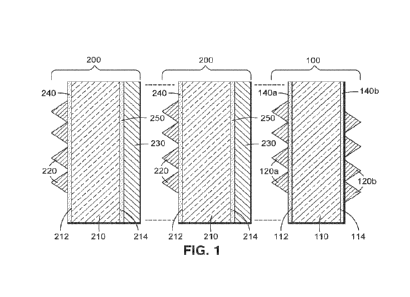
[0021] Figure 1 is a cross-sectional view of a base layer and two removable
lens
layers of a removable lens stack according to an embodiment of the present
disclosure; and
[0022] Figure 2 is a cross-sectional view of the removable lens stack.
DETAILED DESCRIPTION
[0023] The present disclosure encompasses various embodiments of removable
lens
stacks and manufacturing methods thereof. The detailed description set forth
below in
connection with the appended drawings is intended as a description of several
currently contemplated embodiments and is not intended to represent the only
form in
which the disclosed invention may be developed or utilized. The description
sets forth
the functions and features in connection with the illustrated embodiments. It
is to be
understood, however, that the same or equivalent functions may be accomplished
by
different embodiments that are also intended to be encompassed within the
scope of
the present disclosure. It is further understood that the use of relational
terms such as
first and second and the like are used solely to distinguish one from another
entity
without necessarily requiring or implying any actual such relationship or
order
between such entities.
[0024] Figure 1 is a cross-sectional view of a base layer 100 and two
removable
lens layers 200, which may be stacked together to form a removable lens stack
10 as
shown in cross-section in Figure 2. The base layer 100 of the removable lens
stack 10
may be affixed to a surface such as a goggle lens or visor or a transparent
window of a
surgical helmet, hood, or gown, for example, or alternatively may be attached
at a
perimeter thereof to a frame such that the removable lens stack 10 itself
serves as the
lens, visor, face shield, etc. (i.e. without being affixed to a surface). In
the example of
Figures 1 and 2, two removable lens layers 200 are shown, which are stacked on
the
base layer 100 to form the removable lens stack 10. However, it is
contemplated that
there may be more than two removable lens layers 200 or that there may be only
a
CA 03227005 2024- 1-25
WO 2023/009190
PCT/US2022/025996
single removable lens layer 200. As shown, each of the removable lens layers
200
may comprise a substrate 210 and a moth eye coating 220 on a first side 212
thereof.
The base layer 100 may likewise comprise a substrate 110 and a moth eye
coating
120a on a first side 112 thereof, as well as an optional moth eye coating 120b
on a
5 second side 114 opposite the first side 112. Owing to the moth eye
coatings 120a,
120b, 220, the removable lens stack 10 may have very low reflectance and,
accordingly, may exhibit a visible light transmission (VLT) of greater than
95% or in
some cases greater than 98% (e.g. >99% with reflections sub 1%).
[0025] Unlike conventional removable lenses, each removable lens layer 200 may
additionally comprise a fluoropolymer coating 230 on a second side 214 of the
substrate 210 opposite the first side 212. As such, when the removable lens
layer(s)
200 are stacked on top of the base layer 100 with the second side 214 of each
substrate 210 facing the first side 112, 212 of the immediately preceding
substrate
110, 210 (which may be the substrate 210 of an immediately preceding removable
lens layer 200 or the substrate 110 of the base layer 100 as the case may be),
the
fluoropolymer coating(s) 230 may abut the moth eye coatings 120a, 220. Upon
laminating the stacked removable lens layer(s) 200 to the base layer 100, each
fluoropolymer coating 230 may thus be molded to fit the moth eye coating 120a,
220
of the immediately preceding layer 100, 200. The resulting mechanical
interlocking of
the moth eye coatings 120a, 220 with the molded female patterns corresponding
thereto formed in the adjacent fluoropolymer coatings 230 may function
similarly to a
zipper to fix the adjacent layers together. Owing to this mechanical
interlocking, the
use of an acrylic or other tacky adhesive on the moth eye coating 120a, 220
may be
entirely avoided, preventing the increased peel strength associated with such
conventional adhesives collecting around the bumps of the moth eye coating
120a,
220. Thus, the removable lens layer(s) 200 may advantageously have a much
lower
peel strength, which may be less than 100 grams per inch and may, for example,
be
between 15 and 50 grams per inch or more particularly between 15 and 30 grams
per
inch (e.g. 25 grams per inch), making it possible for the wearer to remove
each layer
200 as desired with a reasonable amount of pulling force. (It is noted that
the use of a
tacky adhesive to affix the base layer 100 to a surface may not present a
problem
since the base layer 100 need not be removable and thus an increased peel
strength
CA 03227005 2024- 1-25
WO 2023/009190
PCT/US2022/025996
6
caused by buildup of adhesive around the bumps of the optional moth eye
coating
120b may be acceptable.)
[0026] The substrate 110, 210 of each layer 100, 200 may comprise a
transparent
polymer such as polyethylene terephthalate (PET) and may be 1 to 10 mil thick,
for
example, around 2 mil thick for the substrate 210 of each removable lens layer
200
with the substrate 110 of the base layer 100 being the same thickness or
typically
thicker (e.g. 7 mil). The moth eye coating 220 of each of the removable lens
layers
200, as well as the moth eye coating(s) 120a, 120b of the base layer 100, may
comprise a polymer and may typically be made of a hard polymer such as glassy
carbon having a Mohs hardness of 7, for example. The moth eye coating 120a,
120b,
220 may define a pattern of nano sized micro-projections or bumps (e.g.
transparent
cones) on the surface of the substrate 110, 210 with dimensions on the order
of the
wavelength of light (e.g. visible light), such as half-wave pitch and/or half-
wave
height, to produce the antireflective effect. For example, the pitch and/or
height of the
bumps may be 200-375 nm. Various shapes are possible for the bumps of the moth
eye coating 120a, 120b, 220, including rounded or rectangular raised surfaces
instead
of cones, for example.
[0027] The moth eye coating 120a, 120b, 220 may be refractive index matched
(e.g.
to within 0.2) with the substrates 110, 210 and with the fluoropolymer
coating(s) 230,
as well as with any adhesives that may be used (as described below), such that
the
entire removable lens stack 10 may have a consistent index of refraction (e.g.
within
0.2). However, because the refractive index interface between the air and the
removable lens stack 10 may be effectively eliminated by the outermost moth
eye
coating 220 (as the interface appears like a gradient rather than a sudden
change in
material from the perspective of incident light), it is not necessary to index
match the
removable lens stack 10 to air (n = 1). Therefore, it is contemplated that a
wide
variety of materials may be used for the substrates 110, 210 and other
components of
the removable lens stack 10.
[0028] In general, when building a conventional removable lens stack, a
removable
bonding material is used to wet each pair of adjacent surfaces together. The
term
"wetting," in this context, may refer to when two surfaces come in such close
contact
with each other that the contact displaces all of the air in between the two
surfaces,
CA 03227005 2024- 1-25
WO 2023/009190
PCT/US2022/025996
7
allowing for good bonding. Whereas simply laying one lens on top of another
lens
does not disperse the air trapped between the lenses, an acrylic removable
adhesive
may be used to wet the surfaces together and promote bonding. By matching the
refractive index of the adhesive with the refractive index(es) of the lenses
(e.g. to
within 0.2), visible light may stay at a constant speed at the interfaces,
minimizing
reflections. An example of such a system may be found in U.S. Patent No.
9,295,297,
entitled "Adhesive Mountable Stack of Removable Layers," the entire contents
of
which is expressly incorporated by reference herein. However, because adhesive
is
tacky to the touch, issues arise when bonding two surfaces together where one
or both
surfaces have a moth eye coating. In particular, as described above, the
adhesive fills
in around the micro-projections of the moth eye coating, drastically
increasing the
peel strength beyond what is functionally suitable for a removable lens stack.
[0029] Therefore, in order to wet the surfaces of the substrates 110, 210
together
and achieve the preferred peel strength in the disclosed removable lens stack
10, the
fluoropolymer coating(s) 230 may be provided on the second side 214 of each
substrate 210. The fluoropolymer coating 230 may be an index-matched (e.g. to
within 0.2) soft fluoropolymer such as fluorinated ethylene-propylene
copolymer
(FEP), perfluoroalkoxy alkane (PFA), or tetrafluoroethylene perfluoro(methyl
vinyl
ether) (MFA) that is not tacky to the touch but is moldable under laminating
pressure
to produce a debossed (female) pattern corresponding to the bumps of the
abutting
moth eye coating 120a, 220.
[0030] In some cases, an adhesion treatment 140a, 240 may be provided between
the substrate 110 and moth eye coating 120a of the base layer 100 and/or
between the
substrate 210 and moth eye coating 220 of each removable lens layer 200.
Likewise,
if the substrate 110 of the base layer 100 further includes a moth eye coating
120b on
the second side 114 thereof, an adhesion treatment 140b may be provided
between the
substrate 110 and the moth eye coating 120b. In each removable lens layer 200,
an
adhesion treatment 250 may similarly be provided between the substrate 210 and
the
fluoropolymer coating 230. The adhesion treatments 140a, 140b, 240, 250 may
comprise a pressure sensitive adhesive such as a silicone adhesive (e.g. a
polydimethyl/methylvinyl siloxane polymer and resin dispersed in
toluene/isopropyl
alcohol such as an adhesive sold under the name DOWSILTM 7655 Adhesive or
CA 03227005 2024- 1-25
WO 2023/009190
PCT/US2022/025996
8
DOWSILTM 7656 Adhesive by the Dow Chemical Company). The adhesive may be
index matched (e.g. to within 0.2) with the substrates 110, 210 and other
elements of
the removable lens stack 10 as noted above.
[0031] The base layer 100 and one or more removable lens layers 200 may be
manufactured by coating each substrate 110, 210 with the moth eye coating(s)
120a,
120b, 220 and fluoropolymer coating 230, which may in some cases be adhered to
the
substrates 110, 210 by adhesion treatments 140a, 140b, 240, 250 as described
above.
In order to improve adhesion, it is also contemplated that a corona treatment
may be
applied between the substrate 110, 210 and the moth eye coating 120a, 120b,
220,
and/or between the substrate 210 and the fluoropolymer coating 220. This may
ensure
that the fluoropolymer coating 220 remains with the outermost removable lens
layer
200 as it is pulled off the removable lens stack 10, for example. The corona
treatment
may be applied instead of or in addition to the above-described adhesion
treatments
140a, 140b, 240, 250. The removable lens layer(s) 200 may then be stacked on
top of
the base layer 100 such that the second side 214 of the substrate 210 of each
removable lens layer 200 faces the first side 112. 212 of the substrate 110,
210 of an
immediately preceding layer from among the base layer 100 and the one or more
removable lens layers 200 (as the case may be). In the illustrated example
shown in
Figures 1 and 2, a first removable lens layer 200 (shown in the center of each
figure)
is stacked on the base layer 100 and a second removable lens layer 200 (shown
in the
left-hand side of each figure) is stacked on the first removable lens layer
200.
Additional removable lens layers 200 may similarly be provided and added to
the
stack.
[0032] The removable lens layer(s) 200 may then be laminated to the base layer
100
under pressure with or without heat, for example, under pressure at a
temperature less
than 40 'C. It should be noted that the base layer 100 and removable lens
layer(s) 200
may be laminated together in a single lamination process or in multiple
lamination
processes, for example, with each removable lens layer 200 added to the stack
in a
separate lamination process (or with multiple removable lens layers 200 being
laminated together before being laminated to the base layer 100). As a result
of the
lamination, each fluoropolymer coating 230 may be molded to fit the moth eye
coating 120a, 220 of the immediately preceding layer. In particular, the hard
bumps of
CA 03227005 2024- 1-25
WO 2023/009190
PCT/US2022/025996
9
the moth eye coating 120a, 220 may press into the soft fluoropolymer coating
230 to
produce the corresponding debossed (female) pattern in the fluoropolymer
coating
230. In this way, the above-described mechanical interlocking between the
layers 100,
200 may be achieved to produce the desired peel strength (e.g. 25 grams per
inch)
without the use of tacky adhesives between the layers 100, 200 that might
otherwise
fill in between the bumps and increase the peel strength too much. At the same
time,
the air between the layers 100, 200 may be expelled during the laminating
process,
allowing for wetting of the opposing layers 100, 200 (and slight adhesion as a
result),
while the refractive index interface may be effectively eliminated due to the
index
gradient created by the architecture of the moth eye coatings 120a, 220. The
resulting
visible light transmission (VLT) of the removable lens stack 10 may be greater
than
95% (e.g. 96% with 4% reflection), as opposed to 92% with 8% reflection that
might
be found in an uncoated lens. In some cases, the VLT may be greater than 98%
(e.g.
>99%), especially when the moth eye coating 120b is provided so that there are
moth
eye coatings 120a, 120b, 220 on both sides of the stack 10.
[00331 When the removable lens stack 10 is incorporated into eyewear and being
worn, the wearer may easily peel off the outermost removable lens layer 200 to
reveal
an unblemished removable lens layer 200 (or the base layer 100) underneath. In
the
case of a removable lens stack 10 having multiple removable lens layers 200,
the
pulling force used to remove the outermost removable lens layer 200 may
generally
involve an initial outward force (perpendicular to the stack 10) as the wearer
lifts the
outermost removable lens layer 200 off the stack 10 on one side to separate it
from the
other removable lens layers 200 (e.g. by grasping an easily accessible tab on
one side
of the stack 10), followed by a continuous sideways force (with a component
parallel
to the stack 10) as the wearer peels the outermost removable lens layer 200
off. It is
contemplated that the continuous sideways force that is responsible for the
majority of
the separation of the removable lens layers 200 may have more of a tendency to
lift
off the outermost removable lens layer 200 than to separate subsequent layers
200
underneath. Therefore, the wearer can readily peel off one layer 200 at a time
without
accidentally tearing off additional layers 200 of the removable lens stack 10.
[0034] The above description is given by way of example, and not limitation.
Given
the above disclosure, one skilled in the art could devise variations that are
within the
CA 03227005 2024- 1-25
WO 2023/009190
PCT/US2022/025996
scope and spirit of the invention disclosed herein. Further, the various
features of the
embodiments disclosed herein can be used alone, or in varying combinations
with
each other and arc not intended to be limited to the specific combination
described
herein. Thus, the scope of the claims is not to be limited by the illustrated
5 embodiments.
CA 03227005 2024- 1-25