Note: Descriptions are shown in the official language in which they were submitted.
WO 2023/018619
PCT/US2022/039579
SIMULTANEOUS MULTI-POLARIZATION RECEIVING WITH
CROSS-POLARIZATION INTERFERENCE CANCELLATION
CROSS-REFERENCE TO RELATED APPLICATIONS
[0001] This application claims priority to U.S. Non-Provisional Application
No.
17/557,832, filed December 21, 2021, entitled "SIMULTANEOUS MULTI-
POLARIZATION RECEIVING WITH CROSS-POLARIZATION INTERFERENCE
CANCELLATION-, which claims priority to U.S. Provisional Patent Application
No.
63/231,103, filed on August 9, 2021, entitled -Cancellation Of Cross-Pole
Interference," the
disclosure of which is hereby incorporated by reference in its entirety for
all purposes.
FIELD
[0002] Embodiments relate generally to radiofrequency receivers; and, more
particularly, to
cancelation of cross-polarization interference during simultaneous receipt of
radiofrequency
signals in multiple orthogonal polarizations.
BACKGROUND
[0003] In radiofrequency communication networks, signals are typically
transmitted by
transmitters and received by receivers according to particular polarization
orientations
(referred to herein as "polarization" for simplicity). For example, a
satellite communication
signal can be transmitted and received using vertical polarization, horizontal
polarization,
right-hand circular polarization, left-hand circular polarization, etc. Even
though a particular
signal may be transmitted in a single polarization, receipt of the signal may
be impacted by
interference both in the same polarization and in one or more other
polarizations.
Interference received in polarizations other than the polarization of the
signal can be referred
to as cross-polarization interference.
[0004] Some radiofrequency communication networks simultaneously communicate
one or
more signals over a single frequency channel in multiple (e.g., two)
polarizations, such as to
maximize spectral efficiency. In theory, the multiple polarizations are
precisely orthogonal,
so that the simultaneous communications do not mutually interfere. However, in
real-world
applications, the multiple communications tend not to be precisely orthogonal,
and each
communication becomes a source of cross-polarization interference to the other
or others.
For example, signals are simultaneously transmitted in vertical polarization
over a first
1
CA 03228271 2024- 2-7
WO 2023/018619
PCT/US2022/039579
channel and in horizontal polarization over a second channel. The signals
received over the
first channel will tend to include both the vertically polarized signal and
horizontally
polarized interference from the second channel, and the signal received over
the second
channel will tend to include both the horizontally polarized signal and
vertically polarized
interference from the second channel. The cross-polarization interference can
tend to
degrade the receiver performance, such as by increasing symbol error rate and
degrading
signal-to-noise ratio (SNR).
SUMMARY
[0005] Embodiments described herein provide cancelation of cross-polarization
interference during simultaneous receipt of radiofrequency signals in multiple
orthogonal
polarizations. For example, a radiofrequency receiver simultaneously receives
an X-signal in
a first polarization and a Y-signal in a second polarization over a same
frequency channel.
Even though the polarizations are nominally orthogonal, each signal
contributes some cross-
polarization interference to the other. Each signal is received and
demodulated by a
corresponding demodulator to generate corresponding X-symbol and Y-symbol
decision
signals, both referenced to a common clock domain. An X-channel adaptive
canceler
generates an X-output signal by using one or more Y-symbol decision signals
adaptively to
cancel the cross-polarization interference produced by the Y-signal, and a Y-
channel adaptive
canceler generates a Y-output signal by using one or more X-symbol decision
signals
adaptively to cancel the cross-polarization interference produced by the X-
signal. The
resulting X-output signal and Y-output signal can be further decoded and
output by the
receiver to downstream systems and/or components.
[0006] According to one set of embodiments, a system is provided for
cancelation of cross-
polarization interference in a radiofrequency receiver that simultaneously
receives an X-
signal in a first polarization and a Y-signal in a second polarization over a
same frequency
channel. The first polarization is nominally orthogonal to the second
polarization. The
system includes: an X-demodulator to receive an X-input signal and to generate
one or more
X-symbol decision signals at an X-symbol decision output based on the X-input
signal, the
X-input signal being the X-signal with Y-cross-polarization interference
contributed by
interference from the Y-signal; a Y-demodulator to receive a Y-input signal
and to generate
one or more Y-symbol decision signals at a Y-symbol decision output based on
the Y-input
signal, the Y-input signal being the Y-signal with X-cross-polarization
interference
contributed by interference from the X-signal; an X-channel adaptive canceler
(X-CAC)
2
CA 03228271 2024- 2-7
WO 2023/018619
PCT/US2022/039579
coupled with the X-demodulator and the Y-demodulator, and configured to apply
the Y-
symbol decision output to an X-feedback control loop to adaptively cancel
contributions of
the Y-cross-polarization interference from the X-symbol decision output to
generate an X-
output signal; and a Y-channel adaptive canceler (Y-CAC) coupled with the X-
demodulator
and the Y-demodulator, and configured to apply the X-symbol decision output to
a Y-
feedback control loop to adaptively cancel contributions of the X-cross-
polarization
interference from the Y-symbol decision output to generate a Y-output signal.
[0007] According to another set of embodiments, a method is provided for
cancelation of
cross-polarization interference in a radiofrequency receiver that
simultaneously receives an
X-signal in a first polarization and a Y-signal in a second polarization over
a same frequency
channel. The first polarization is nominally orthogonal to the second
polarization. The
method includes: receiving an X-input signal as the X-signal with Y-cross-
polarization
interference contributed by interference from the Y-signal; receiving a Y-
input signal as the
Y-signal with X-cross-polarization interference contributed by interference
from the X-
signal; generating one or more X-symbol decision signals at an X-symbol
decision output
based on the X-input signal; generating one or more Y-symbol decision signals
at a Y-symbol
decision output based on the Y-input signal; generating an X-output signal by
applying the Y-
symbol decision output to an X-feedback control loop to adaptively cancel
contributions of
the Y-cross-polarization interference from the X-symbol decision output; and
generating a Y-
output signal by applying the X-symbol decision output to a Y-feedback control
loop to
adaptively cancel contributions of the X-cross-polarization interference from
the Y-symbol
decision output.
[0008] This summary is not intended to identify key or essential features of
the claimed
subject matter, nor is it intended to be used in isolation to determine the
scope of the claimed
subject matter. The subject matter should be understood by reference to
appropriate portions
of the entire specification of this patent, any or all drawings, and each
claim.
[0009] The foregoing, together with other features and embodiments, will
become more
apparent upon referring to the following specification, claims, and
accompanying drawings.
BRIEF DESCRIPTION OF THE DRAWINGS
[0010] The present disclosure is described in conjunction with the appended
figures:
100111 FIG. 1 shows a simplified block diagram of a radiofrequency receiver;
3
CA 03228271 2024- 2-7
WO 2023/018619
PCT/US2022/039579
[0012] FIG. 2 shows another high-level block diagram of a partial
radiofrequency receiver,
according to various embodiments described herein;
[0013] FIG. 3 shows a block diagram of an illustrative implementation of a
partial
radiofrequency receiver, according to various embodiments described herein;
[0014] FIG. 4 shows a block diagram of an implementation of an illustrative
multi-tap
canceler for cancelation of cross-polarization interference, according to
various embodiments
described herein;
[0015] FIG. 5 shows a block diagram of an illustrative implementation of a
partial
radiofrequency receiver to handle frequency offsets between the X-signal and
the Y-signal,
according to various embodiments described herein; and
[0016] FIG. 6 shows a flow diagram of an illustrative method for cancelation
of cross-
polarization interference in a radiofrequency receiver, according to various
embodiments
described herein.
[0017] In the appended figures, similar components and/or features may have
the same
reference label. Further, various components of the same type may be
distinguished by
following the reference label by a second label (e.g., a lower-case letter)
that distinguishes
among the similar components. If only the first reference label is used in the
specification,
the description is applicable to any one of the similar components having the
same first
reference label irrespective of the second reference label.
DETAILED DESCRIPTION
[0018] Embodiments of the disclosed technology will become clearer when
reviewed in
connection with the description of the figures herein below. In the following
description,
numerous specific details are set forth to provide a thorough understanding of
the present
invention. However, one having ordinary skill in the art should recognize that
the invention
may be practiced without these specific details. In some instances, circuits,
structures, and
techniques have not been shown in detail to avoid obscuring the present
invention.
[0019] Some radiofrequency communication networks simultaneously communicate
signals over a single frequency channel in multiple (e.g., two) polarizations,
such as to
maximize spectral efficiency. In theory, the multiple polarizations are
precisely orthogonal,
so that the simultaneous communications do not mutually interfere. However, in
real-world
applications, the multiple communications tend not to be precisely orthogonal,
such that each
4
CA 03228271 2024- 2-7
WO 2023/018619
PCT/US2022/039579
communication becomes a source of cross-polarization interference to the other
or others. In
effect, the receiver simultaneously receives the signals via two receive paths
that are mutually
interfering. Such mutual interference due to cross-polarization can tend to
degrade the
receiver performance, such as by increasing symbol error rate and degrading
signal-to-noise
ratio (SNR).
[0020] Embodiments described herein include techniques for canceling (e.g.,
substantially
eliminating) such cross-polarization interference in receivers that
simultaneously receive
signals over a same frequency channel in multiple polarizations. For example,
two receive
paths (X and Y) correspond to two nominally orthogonal polarizations. For
example, a X-
channel received signal corresponds a first (e.g., vertically) polarized
transmission of the
signal, and a Y-channel received signal corresponds a second (e.g.,
horizontally) polarized
transmission of the signal. Each channel's signal has a respective signal
characteristics (e.g.,
delay offset, amplitude, frequency offset, etc.); and each channel is affected
by cross-
polarized interference contributions from the other channel that also have
respective signal
characteristics. Each of an X-demodulator and a Y-demodulator receives a
respective one of
the X-channel signal and the Y-channel signal and generates X-channel symbol
decision
signals and Y-channel symbol decision signals, respectively, based on
estimates of their
respective received signal and cross-polarization interference
characteristics. An X-channel
adaptive canceler (X-CAC) uses the Y-channel symbol decision signals to cancel
cross-
polarization interference from the Y-channel, and a Y-channel adaptive
canceler (Y-CAC)
uses the X-channel symbol decision signals to cancel cross-polarization
interference from the
X-channel. The interference-canceled signals output by the X-CAC and the Y-CAC
can be
decoded into a digital output signal for output by the receiver (e.g., to a
media receiver and/or
playback device).
[0021] FIG. 1 shows a simplified block diagram of a radiofrequency receiver
100. In a
modern radiofrequency communication network, data streams (e.g., streams of
digital bits)
may be encoded into analog signals according to some defined protocol or
protocols, and the
analog signals may be communicated wirelessly over one or more carrier
frequencies (i.e.,
one or more frequency channels) at one or more polarizations. A receiving
antenna (not
shown) tuned to a particular carrier frequency and oriented to a particular
polarization can
receive analog signals transmitted over that carrier frequency and in that
polarization.
[0022] As noted above, embodiments described herein operate in context of
simultaneous
receipt of signals at multiple (e.g., two) nominally orthogonal polarizations.
The term
5
CA 03228271 2024- 2-7
WO 2023/018619
PCT/US2022/039579
"nominal" (or "nominally", or the like) refers to the designed intent of the
condition with the
recognition that a real-world implementation will likely (or even certainly)
fail to precisely
meet the condition. For example, a communication system can be designed to
transmit a first
signal in a nominally vertical polarization orientation and a second signal in
a nominally
horizontal polarization orientation, such that the signals are nominally
orthogonally polarized
and do not interfere. Anyone of skill in the art will recognize, however, that
it may be
impractical or impossible to produce and/or maintain perfect orthogonality,
and the two
signals will tend to interfere by cross-polarization interference. As such,
reference herein to a
first polarization that is nominally orthogonal to a second polarization," or
the like, conveys
that the two polarizations are intended by design to be orthogonal with the
recognition that
perfect orthogonality will not be attainable and some cross-polarization
interference will
occur.
[0023] In this context, at least two analog signals will be received over the
radiofrequency
channel in different polarizations. As illustrated, the radiofrequency
receiver 100 receives the
transmitted analog signals as multiple input signals 105 and generates one or
more output
signals 155 for use by other components. For example, in a satellite
television network, a
digital bit stream representing digital television content can be encoded onto
multiple,
nominally orthogonal analog transmissions and received over the radiofrequency
channel by
the radiofrequency receiver 100 as the input signals 105. The radiofrequency
receiver 100
can process the received input signals 105 to recover and decode the digital
bit stream, which
it can then send as the output signal(s) 155 to a digital television, or other
digital media
storage or playback appliance.
[0024] As illustrated, the received input signals 105 can be received at the
input to a
demodulator 110. The demodulator 110 can include a demodulator clock 115,
amplitude/phase/frequency (APF) recovery blocks 120, symbol timing recovery
blocks 125,
and matched filter blocks 130. As described below, the matched filter blocks
130 can be
implemented as part of the symbol timing recovery blocks 125. Some embodiments
of the
demodulator 110 can include additional components, such as additional analog-
to-digital
converters (ADCs), filters, amplifiers, controllers, etc. As illustrated, the
input signals 105
can initially be passed to the APF recovery blocks 120, which can estimate the
amplitude,
phase, and/or frequency of the input signals 105 and can normalize the input
signals 105,
accordingly. For example, subsequent blocks of the radiofrequency receiver 100
may be
designed to operate at (e.g., to expect) a particular amplitude, phase, and/or
frequency.
6
CA 03228271 2024- 2-7
WO 2023/018619
PCT/US2022/039579
[0025] The normalized input signals 105 can be passed to the symbol timing
recovery
blocks 125 and the matched filter blocks 130. The symbol timing recovery
blocks 125 can
sample the normalized input signals 105 to estimate a stream of symbols (e.g.,
bits) encoded
by the input signals 105. The matched filter blocks 130 can attempt to
correlate a template
signal to the estimated symbol stream of the normalized input signals 105
(e.g., by computing
a convolution of the normalized input signals 105 with a time-reversed
conjugate of the
template signal) in a manner that seeks to maximize signal-to-noise ratio
(SNR). While the
illustrated configuration shows the symbol timing recovery blocks 125 as a
separate block
prior to the matched filter blocks 130, features of those blocks can be
performed in any
suitable manner. For example, as described below, the matched filter blocks
130 can be
implemented as part of the symbol timing recovery blocks 125.
[0026] Embodiments of the demodulator clock 115 can effectively establish a
receiver
clock domain. For example, symbols are encoded in the input signals 105 at a
particular
symbol rate, and the receiver clock domain can have a frequency that is some
integer multiple
of the symbol rate. The APF recovery blocks 120, symbol timing recovery blocks
125, and
matched filter blocks 130 can be coupled with the demodulator clock 115, so
that recovery of
the symbol stream from the input signals 105 is synchronized with the receiver
clock domain.
In some conventional radiofrequency receivers, similar techniques can be used
to estimate a
symbol stream from a single input signal received at a single polarization.
Such conventional
implementations may not tend to experience appreciable amounts of cross-
polarization
interference, such that a recovered symbol stream can be passed directly to a
decoder for
generation of an output signal. In the contexts described herein, however,
each of the input
signals 105 is afflicted with cross-polarization interference from others of
the input signals
105, which can impact the reliability of symbol estimation.
[0027] As such, the output of the demodulator 110 (i.e., one or more signals
representing
an estimated symbol stream derived from each of the input signals 105) is
passed to a cross-
polarization (x-pol) canceler 140. As described herein, embodiments of the x-
pol canceler
140 can use feedback loops to cancel contributions of cross-polarization
interference from the
demodulator 110 output signals, thereby producing recovered estimated symbol
streams that
are cross-polarization-canceled. The outputs from the x-pol canceler 140
(i.e., the cross-
polarization-canceled recovered estimated symbol streams) can be passed to one
or more
decoder blocks 150 for generation of the output signal(s) 155. For example, as
noted above,
content can be encoded as a digital bit stream, and the digital bit stream can
be encoded onto
7
CA 03228271 2024- 2-7
WO 2023/018619
PCT/US2022/039579
the transmitted radiofrequency signals that are ultimately received as the
input signals 105.
Part of encoding the signals for transmission typically involves adding
additional symbols
(e.g., bits) in accordance with one or more data and/or communication protocol
definitions.
For example, the digital data may be packetized with additional overhead, such
as into data
packets that each include a preamble, post-amble, mid-amble, etc.; and/or with
additional
data to support modulation and/or encoding schemes that help tailor the
robustness of the
communication to packet loss, and/or other concerns. For these and other
reasons, generation
of the output signal 155 by the decoder blocks 150 can involve stripping off
protocol-defined
overhead, and/or otherwise decoding (e.g., and possibly re-encoding) the
symbol stream
according to protocol definitions, to generate suitable output signal(s) 155
for use by
downstream components.
100281 While FIG. 1 shows the demodulator 110 and the x-pol canceler 140 each
as a
single box, each is implemented to support multiple receive paths for the
multiple input
signals 105. FIG. 2 shows another high-level block diagram of a partial
radiofrequency
receiver 200, according to various embodiments described herein. The partial
radiofrequency
receiver 200 can be a partial implementation of the radiofrequency receiver
100 of FIG. 1
(e.g., without the decoder blocks 150). For example, as illustrated in FIG. 2,
the demodulator
110 of FIG. 1 can be implemented as an X-demodulator 210-1 and a Y-demodulator
210-2,
and the x-pol canceler 140 of FIG. 1 can be implemented as an X-channel
adaptive canceler
and a Y-channel adaptive canceler.
100291 The illustrated implementation specifically shows the X-channel
adaptive canceler
implemented as an X-channel least mean squares (LMS) canceler (X-LMSC) 220-1,
and the
Y-channel adaptive canceler implemented as a Y-channel LMS canceler (Y-LMSC)
220-2.
Such implementations generally suggest that each LMSC 220 includes one or more
control
loops to adaptively cancel cross-polarization interference, and that each
control loop
generally generates an error (corresponding to the cross-polarization
interference), integrates
and attenuates the error, and generates a feedback signal based on the error
to cancel the
cross-polarization interference. In some such implementations, each control
loop can
implement such features as a first-order control loop. Even though various
embodiments are
illustrated and described herein with specific reference to LMS-based
cancelers (i.e., X-
LMSCs and Y-LMSCs) with first-order control loops, etc., it will be
appreciated that other
types of adaptive control can be used to implement the cross-polarization
noise cancelation.
For example, the X-channel and Y-channel adaptive cancelers can be implemented
using
8
CA 03228271 2024- 2-7
WO 2023/018619
PCT/US2022/039579
non-LMS-based adaptive control techniques and/or using higher-order (e.g.,
second-order)
control loops, or in any other suitable manner.
[0030] To avoid over-complicating the figures and descriptions, embodiments
are
discussed in context of simultaneously receiving two input signals 205 over a
same frequency
channel. Each of the input signals 205 is simultaneously communicated in a
respective one
of two nominally orthogonal polarization orientations. Techniques described
herein can be
extended to contexts where more than two input signals are simultaneously
received. As
illustrated, the first input signal can be referred to as the -X-input" signal
205-1, and the
second input signal can be referred to as the "Y-input" signal 205-2. Though
the input
signals 205 are nominally orthogonal, each includes cross-polarization
interference from the
other. For the sake of convention, the description herein refers to an "X-
signal" as a first
encoded data signal as it traverses the radiofrequency channel in a first of
the nominally
orthogonal polarizations, and a "Y-signal" as a second encoded data signal as
it traverses the
radiofrequency channel in the second of the nominally orthogonal
polarizations. The
received X-input signal 205-1 includes the X-signal and cross-polarization
interference
contributed by interference from the Y-signal, and the received Y-input signal
205-2 includes
the Y-signal and cross-polarization interference contributed by interference
from the X-
signal.
[0031] The X-input signal 205-1 is received by the X-demodulator 210-1, and
the Y-input
signal 205-2 is received by the Y-demodulator 210-2. The X-demodulator 210-1
and the Y-
demodulator 210-2 can be referenced to a same demodulator clock domain. For
example, the
X-demodulator 210-1 and the Y-demodulator 210-2 can be coupled to, and clocked
according
to, a same demodulator clock 115, such as described with reference to FIG. 1.
Each
demodulator 210 can generate one or more decision signals 215 (also referred
to herein as
"symbol decision signals"), such as a soft decision signal, a hard decision
signal, a known
decision signal, etc. In particular, the X-demodulator 210-1 generates and
outputs one or
more X-decision signals 215-1 (or "X-symbol decision signals") based on the X-
input signal
205-1, and the Y-demodulator 210-2 generates and outputs one or more Y-
decision signals
215-2 (or -Y-symbol decision signals") based on the Y-input signal 205-2.
[0032] The X-decision signals 215-1 and the Y-decision signals 215-2 can be
used by the
LMSCs 220 to cancel cross-polarization interference from the X-decision
signals 215-1 and
the Y-decision signals 215-2, respectively. As noted above, the X-input signal
205-1
includes cross-polarization interference contributions from the Y-signal ("Y-
cross-
9
CA 03228271 2024- 2-7
WO 2023/018619
PCT/US2022/039579
polarization interference"). As such, the X-decision signals 215-1 (i.e.,
representing the
estimated symbol stream as recovered from the X-input signal 205-1) also
include Y-cross-
polarization interference contributions. The X-LMSC 220-1 is coupled with both
the X-
demodulator 210-1 and the Y-demodulator 210-2. The X-LMSC 220-1 applies one or
more
of the Y-decision signals 215-2 (received from the Y-demodulator 210-2) to an
X-feedback
control loop to adaptively cancel contributions of the Y-cross-polarization
interference from
the X-decision signals 215-1 (received from the X-demodulator 210-1) to
generate an X-
output signal 225-1. Similarly, the Y-input signal 205-2 includes cross-
polarization
interference contributions from the X-signal ("X-cross-polarization
interference"), and thus
the Y-decision signals 215-2 (i.e., representing the estimated symbol stream
as recovered
from the Y-input signal 205-2) also includes X-cross-polarization interference
contributions.
The Y-LMSC 220-2 is coupled with both the X-demodulator 210-1 and the Y-
demodulator
210-2. The Y-LMSC 220-2 applies one or more of the X-decision signals 215-1
(received
from the X-demodulator 210-1) to a Y-feedback control loop to adaptively
cancel
contributions of the X-cross-polarization interference from the Y-decision
signals 215-2
(received from the Y-demodulator 210-2) to generate a Y-output signal 225-2.
[0033] As described herein, each of the X-control loop of the X-LMSC 220-1 and
the Y-
control loop of the Y-LMSC 220-2 can be implemented as a least mean squares
(LMS) first-
order control loop. For example, such a loop can generally use negative
feedback to
adaptively converge on a set of component parameters that optimizes
cancelation of
interference from the cross-polarization interference. The converged-upon
parameters can be
dynamically updated with any changes in characteristics of the interference.
In some
embodiments, the decision signals 215 are oversampled so that there are
multiple samples for
each estimated recovered symbol, each having its own corresponding sample
timing. In
some such embodiments, the each LMSC 220 can implement its respective control
loop as
multiple control loops that each seeks to cancel interference with respect to
the sample timing
of a respective one of the multiple samples. Some embodiments described herein
include
additional features, such as to handle frequency offsets between the X-signal
and the Y-
signal.
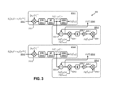
[0034] FIG. 3 shows a block diagram of an illustrative implementation of a
partial
radiofrequency receiver 300, according to various embodiments described
herein. The partial
radiofrequency receiver 300 can be an implementation of the partial
radiofrequency receiver
200 of FIG. 2. The X-input signal 205-1 is represented as: Di [Ai (X+ al Y)
e'011. As
CA 03228271 2024- 2-7
WO 2023/018619
PCT/US2022/039579
described above, the X-input signal 205-1 includes the X-signal (X) plus cross-
polarization
interference contributions represented as energy from the Y-signal (Y)
attenuated by a
complex coefficient (a1). The X-input signal 205-1 is also received at some
amplitude (Ai),
phase (4n), and delay (Di). Similarly, the Y-input signal 205-2 is represented
by D2 IA2 (Y +
a2 X) e'21, including the Y plus cross-polarization interference contributions
represented as
energy from X attenuated by a complex coefficient (a2). The Y-input signal 205-
2 is also
received at some amplitude (A2), phase (02), and delay (D2). Even though the
signals are
received nominally simultaneously, there can be a mismatch in the delays of
the X-input
signal 205-1 and the Y-input signal 205-2 due to various factors. For example,
slight
differences in cable length between respective receive antennas and the
respective
demodulators 210 can manifest differences between Di and D2.
100351 Each demodulator 220 includes a normalizer 312, a symbol timing
recovery (STR)
block 314, a matched filter (MF) block 316, and a hard/known decision (H/KD)
block 318.
The normalizer 312 can be an implementation of the APF recovery block 120 of
FIG. 1, the
symbol timing recovery (STR) block 314 can be an implementation of the symbol
timing
recovery block 140 of FIG. 1, and the matched filter (MF) block 316 can be an
implementation of the matched filter block 130 of FIG. 1. As illustrated, the
normalizer 312
can be implemented as a multiplier that generates a normalized input signal
based on a
complex product of the input signal 205 and the inverse of signal
characteristics estimated
from the input signal 205. For example, the normalizer 312-1 in the X-
demodulator 210-1
estimates and inverts the amplitude and phase of the X-input signal 205-1 as
[Ai e A11-1, such
that performing the complex product effectively normalizes (e.g., cancels) out
the amplitude
and phase characteristics from the X-input signal 205-1. Similarly, the
normalizer 312-2 in
the Y-demodulator 210-2 estimates and inverts the amplitude and complex phase
of the Y-
input signal 205-2 as [A2 e A21-1, such that performing the complex product
effectively
normalizes (e.g., cancels) out the amplitude and phase characteristics from
the Y-input signal
205-2.
[0036] In each demodulator 210, the STR block 314 can seek to estimate a
recovered
symbol stream from the normalized input signal 205. For example, a delay-
locked loop can
attempt to lock onto peaks, or other features of the input signals 205, to
identify symbol
timing and symbol boundaries. Though shown as two separate blocks, the STR
blocks 314
and the MF blocks 316 work together to generate a "soft decision" (SD) output.
In some
implementations, the MF blocks 316 are implemented within the STR blocks 314.
The input
11
CA 03228271 2024- 2-7
WO 2023/018619
PCT/US2022/039579
to the STR block 314 is the amplitude- and phase-corrected output from the
normalizer 312,
which includes an encoded stream of symbols. The STR block 314 seeks to
recover the
symbol timing, such as by estimating a sampling location (e.g., sample period)
until an
optimal periodic sample location is achieved. The MF block 316 can then
perform template
matching, or the like, based on the estimated symbol timing to generate an
output that
corresponds to a recovered complex sample value. The estimate of the recovered
complex
sample value can be considered as the SD output. In some implementations, the
STR block
314 and the MF block 316 are part of a feedback loop. The STR block includes a
symbol
timing interpolator coupled with an input to the MF block 316, and the SD
output from the
MF block 316 is fed back, via a timing error detector and a loop filter, to
the symbol timing
interpolator. In this way, the symbol timing interpolator can dynamically
update its estimate
of the symbol timing based on the feedback.
100371 As noted above, the demodulator clock 115 can define a demodulator
clock domain
(referred to as Do), and the symbol timing recovery by the STR block 314 tends
to
synchronize the symbol timing of the recovered symbol stream (i.e., of the SD
output) to Do.
In effect, the STR block 314 tends to add a variable delay to the normalized
input signal 205
(Di ¨Do for the X-input signal 205-1, and D2 ¨Do for the Y-input signal 205-
2), so that
subsequent processing of the signals in both the X and Y processing paths can
be referenced
to Do. As such, the SD output in the X-demodulator 210-1 can effectively be
considered as
including the X-signal and the interference contribution from the Y-signal
(i.e., aiY), all
referenced to the Do domain, and the SD output in the Y-demodulator 210-2 can
effectively
be considered as including the Y-signal and the interference contribution from
the X-signal
(i.e., a2X), all referenced to the Do domain. This can be seen in FIG. 3 as
the signals at the
outputs of MF block 316-1 and 316-2:
Do [X+ ai = Do [XsT21, and
Do IY + a2X] = Do MD], respectively.
100381 The mutual shift to the same Do assumes that the two demodulators 210
are
referenced to the same clock domain, such as by being coupled with the same
demodulator
clock 115. Still, the type of delay shifting provided by the STR blocks 314
may only be able
to account for slight mismatches between the delays of the input signals 205.
In some
implementations, the STR blocks 314 may be able to tolerate up to
approximately a half-
symbol delay adjustment. For example, if the X-input signal 205-1 and the Y-
input signal
12
CA 03228271 2024- 2-7
WO 2023/018619
PCT/US2022/039579
205-2 are 500 Mega-sample per second (Msps) signals, each symbol is allotted 2
nanoseconds (ns) of symbol time, and such an implementations of the STR blocks
314 would
handle up to approximately 1 ns of mismatch between Di and D2.
[0039] As described with reference to FIG. 2, the output of each demodulator
210 can be
one or more decision signals 215. One such decision signal 215 can be the SD
signals
described above. For example, the signals received as input signals 205 were
initially
transmitted from digital transmitters. In either of the transmitted signals,
any particular
symbol (s) can be considered from a set of symbols (S) in the signal (i.e.,
the symbol can
correspond to an integer value from 0 to S¨ 1). The symbol can be mapped to a
complex
value by a mapping function: M(s) = z = x jy. At the receiver, after
adjusting amplitude and
phase by the normalizer 312, and after recovering symbol timing and performing
matched
filtering by the STR block 314 and the MF block 316, a complex value is
recovered in the SD
output as zsD = 2 z, which is an estimate of the recovered symbol. Certain
features
described herein use this SD output directly as one of the decision signals
215.
[0040] In some embodiments, each demodulator 210 includes one or more other
types of
decision blocks to generate additional and/or different decision signals 215,
such as H/KD
blocks 318. In some implementations, the H/KD blocks 318 use one or more hard
decision
decoding techniques to generate a hard decision (HD) signal. Embodiments of
the H/KD
blocks 318 can generate the HD signal by performing an inverse operation on
the SD output
to attempt to map each recovered complex value back to a corresponding symbol
transmitted
by the transmitter. For example, from each recovered complex value, 2, the
H/KD blocks
318 can generate a guess as to the corresponding transmitted symbol, S. The
guessed symbol,
S, can be used to reapply the mapping described above to obtain ZEID = M().
Thus, the SD
output can include a stream of samples, each representing a raw complex output
value from
the MF block 316 and the HD output can include a stream of estimated recovered
symbol
values obtained by de-mapping SD output samples to a symbol constellation
point and then
remapping (e.g., based on picking the symbol with the closest Euclidean
distance to the SD
output sample). The HD signals for the X-demodulator 210-1 and the Y-
demodulator 210-2
are represented as: Do [ytm] and Do WHD], respectively.
[0041] In addition to (or as an alternative to) soft decision signals and hard
decision signals,
some embodiments generate one or more other types of decision signals 215,
referred to
herein as a "known" decision signal (i.e., Do I õknown] and Do [Known"). One
type of known
decision signal is based on a set of previously known symbols at deterministic
symbol
13
CA 03228271 2024- 2-7
WO 2023/018619
PCT/US2022/039579
locations. For example, as described above, data is encoded onto the X-signal
and the Y-
signal based on one or more protocols, such that a portion of the encoded data
stream can
include certain types of protocol-defined preamble symbols, header symbols,
and/or other
overhead symbols that follow protocol-defined patterns (e.g., sequences). In
some
embodiments, the H/KD blocks 318 can generate the known decision signal based
completely
on prior knowledge of must be transmitted by the transmitter in particular
time locations
(e.g., as defined by protocols, etc.), regardless of what is received at the
demodulators 210.
For example, input signals 205, SD output, etc. can be ignored when generating
the known
decision signals, and the generated known decision signals have symbol values
only in
known locations. In other embodiments, the H/KD blocks 318 can exploit prior
knowledge
of transmitted symbols in certain time locations to verify symbol recovery by
the H/KD
blocks 318, and/or to confidently recover symbols in those known time
locations. For
example, in locations of the recovered symbol stream that correspond to such
sequences of
known symbols, the H/KD blocks 318 can be highly confident of the "correct"
value of
estimated recovered symbols.
[0042] Another type of known decision signal is generated to include estimated
recovered
symbols only where the estimate exceeds a predetermined threshold confidence
level. For
example, as described above, some soft decision techniques are based on
Euclidean distance
from constellation points. Some embodiments of the H/KD blocks 318 can
generate a known
decision signal to include estimated recovered symbol information only where
the Euclidean
distance to ideal constellation points is below a relatively low threshold
distance. In other
embodiments, the H/KD blocks 318 do not generate the known decision signal as
a separate
signal; rather, the H/KD blocks 318 can represent the known decision signals
as indications
of which portions of the HD signal represent high-confidence estimated
recovered symbols
(e.g., based on protocol definition, Euclidean distance, etc.).
[0043] As described below, the various types of decision signals 215 can be
used by control
loops of the LMSCs 220. In general, the SD and HD signals tend to have a
relatively high
symbol density, but relatively low confidence as to the values of the
estimated recovered
symbols; while the known decision signal can have an appreciably smaller
symbol density,
but an appreciably high confidence as to the values of the estimated recovered
symbols. As
such, use of the known decision signals in the LMSC 220 control loops may
yield slower, but
more confident conversion for interference cancelation.
14
CA 03228271 2024- 2-7
WO 2023/018619
PCT/US2022/039579
[0044] One or more of the decision signals 215 from each of the demodulators
210 is sent
to both of the LMSCs 220. Using these decision signals 215, the LMSCs 220 seek
to cancel
the portion of each of the input signals 205 that is con-elated with the other
of the input
signals 205 to generate a respective one of the X-output signal 225-1 and the
Y-output signal
225-2. For example, as described above, an output of the X-demodulator 210-1
(i.e., one or
more of the decision signals 215) can essentially be the X-signal and the Y-
cross polarization
interference, received as the X-input signal 205-1, but after being at least
normalized with
respect to amplitude and phase from normalizer 312-1, delayed to the Do clock
reference
frame by STR block 314-1, and with improved SNR from MF block 316-1. One or
more of
the Y-decision signals 215-2 from the Y-demodulator 210-2 can then be used by
the X-
LMSC 220-1 to isolate and cancel the portions of the X-demodulator 210-1
output that
correlate to the Y-cross-polarization interference, thereby leaving only (or
substantially only)
the X-signal information in the N-output signal 225-1.
[0045] As illustrated, the SD output signal from each demodulator 210 is
provided as the
input to its corresponding LMSC 220. Each LMSC 220 has a control loop (e.g., a
first-order
control loop) that includes a subtracter 322, a first multiplier 324, an
integration-attenuation
path having an integrator 326 and an attenuator 328, and a second multiplier
329. For
example, in the X-LMSC 220-1, an X-subtracter 322-1 generates the X-output
signal 225-1
based on a difference between the X-soft decision signal, Do [.isp], and an X-
feedback signal
generated at the output of the control loop. Each control loop effectively
uses negative
feedback to dynamically converge on cancellation of the cross-polarization
interference.
[0046] A first X-multiplier 324-1 is coupled with the output of X-subtracter
322-1 to
generate a first X-multiplier output signal based on a product of the X-output
signal 255-1
and a conjugate of one of the Y-decision signals 215-2. In some
implementations, the
conjugate of the Y-hard decision signal (one possible output of H/KD block 318-
2, Do WHD])
is used by first multiplier 324-1. In other implementations, the conjugate of
the Y-known
decision signal (another possible output of H/KD block 318-2, Do [fbiown1) is
used by first
multiplier 324-1. As described above, the Y-known decision signal can be
generated to
include only known symbols based on protocol definitions and/or other highly
deterministic
portions of the received signal, or the Y-known decision signal can be
generated otherwise to
include only symbols that can be estimated with at least a predetermined
threshold level of
confidence. In some implementations, the Y soft decision signal (the output of
MF block
316-2, Do [isD1) can be used by first X-multiplier 324-1.
CA 03228271 2024- 2-7
WO 2023/018619
PCT/US2022/039579
[0047] In an X-integration-attenuation path, an X-integrator 326-1 and an X-
attenuator
328-1 are coupled with the output of first X-multiplier 324-1 to generate a
second X-
multiplier output signal by integrating and attenuating the first X-multiplier
output signal
(based on an attenuation factor, k). Though k is constant, the output of the X-
attenuator 328-
1 varies dynamically, as described below. For example, the second X-multiplier
output
signal can begin at a value appreciably less than 1 (e.g., 104, or less), and
can adaptively
converge substantially to an optimal value (e.g., to an estimate of ai) for
canceling the cross-
polarization interference contribution. A second X-multiplier 329-1 is coupled
with the
output of the X-integration-attenuation path to generate the X-feedback signal
based on a
product of the second X-multiplier output signal and one of the Y-symbol
decision signals
215-2. In the illustrated implementation, the Y-soft decision signal is used
by the second X-
multiplier 329-1 to generate the X-feedback signal. In other implementations,
the Y-hard
decision signal can be used by the second X-multiplier 329-1 to generate the X-
feedback
signal. As illustrated, the output of the second X-multiplier 329-1 is coupled
in feedback
with an input of the X-subtracter 322-1.
[0048] As described above, the Y-signal contributes cross-polarization
interference to the
X-input signal 205-1 at a magnitude represented by ai. In effect, over
multiple iterations of
the control loop, the X-integration-attenuation path settles to a value that
corresponds to an
estimate of ai. As such, the X-feedback signal generated at the output of the
control loop by
the second X-multiplier 329-1 is an estimate of aiY, which is the Y-cross-
polarization
interference contribution on the X-input signal 205-1. By feeding this back
and subtracting
this out, the Y-cross-polarization interference contribution can effectively
be removed from
the X-input signal 205-1.
[0049] The Y-LMSC 220-2 can include the same components and can operate in the
same
manner. A Y-subtracter 322-2 generates the Y-output signal 225-2 based on a
difference
between the Y-soft decision signal, Do fsrd, and a Y-feedback signal generated
at the output
of the control loop. A first Y-multiplier 324-2 is coupled with the output of
Y-subtracter
322-2 to generate a first Y-multiplier output signal based on a product of the
Y-output signal
255-2 and a conjugate of one of the X-decision signals 215-1 (e.g., a
conjugate of the X-hard
decision signal, the X-known decision signal, the X-soft decision signal,
etc.). In a Y-
integrati on-attenuation path, a Y-integrator 326-2 and a Y-attenuator 328-2
are coupled with
the output of first Y-multiplier 324-2 to generate a second Y-multiplier
output signal by
integrating and attenuating the first Y-multiplier output signal. A second Y-
multiplier 329-2
16
CA 03228271 2024- 2-7
WO 2023/018619
PCT/US2022/039579
is coupled with the output of the Y-integration-attenuation path to generate
the Y-feedback
signal based on a product of the second Y-multiplier output signal and one of
the X-symbol
decision signals 215-1 (e.g., the X-soft decision signal, or the X-hard
decision signal). The
output of the second Y-multiplier 329-2 is coupled in feedback with an input
of the Y-
subtracter 322-2. The X-signal contributes cross-polarization interference to
the Y-input
signal 205-2 at a magnitude represented by a2, and the Y-integration-
attenuation path is
configured adaptively to settle to a value that con-esponds to an estimate of
0,2. As such, the
Y-feedback signal generated at the output of the control loop by the second X-
multiplier 329-
1 is an estimate of a2X (the X-cross-polarization interference contribution on
the Y-input
signal 205-2), and feeding this back and subtracting this out can effectively
remove the Y-
cross-polarization interference contribution from the X-input signal 205-1.
[0050] FIG. 4 shows a block diagram of an implementation of an illustrative
multi-tap
LMSC 400 for cancelation of cross-polarization interference, according to
various
embodiments described herein. Such a multi-tap approach can tend to handle
more delay
mismatch between the X-signal and the Y-signal than can a single-tap approach.
The multi-
tap LMSC 400 approach can operate on multiple samples in parallel (i.e.,
concurrently) by
associating each of multiple taps 410 to a respective sample time. Each input
signal 205 is
encoded at a particular symbol data rate, such that each symbol has a defined
symbol time,
symbol boundary, etc., and each decision signal 215 output by the demodulators
210 can be
generated at the same symbol rate, or some multiple thereof In some
implementations, each
of the taps 410 is assigned in integer symbol time increments, so that each
tap is effectively
operating on a version of the signal that is delayed by a corresponding
integer number of
symbol times. In other implementations, one or more the decision signals 215
output by the
demodulators 210 are oversampled with respect to the symbol rate of the input
signals 205 by
generating samples (i.e., an estimated symbol recovery sample) at a sample
rate that is a
multiple of the symbol rate. For example, the sample rate of the decision
signals 215 can be
4x, 10x, 16x, or any other suitable rate, such that each symbol time
corresponds to 4 sample
times (i.e., 4 samples, each having a corresponding sample time), 10 sample
times, 16 sample
times, or any other suitable number of sample times, respectively. In such
cases, each tap
410 can be assigned to a respective sample time, which can be a fraction of a
symbol time.
[0051] In general, the multi-tap LMSC 400 includes a "tap" 410 for each of at
least some of
the sample times, such that the multi-tap LMSC 400 can be implemented with M
taps 410, M
is a positive integer. For example, when M = 1, the multi-tap LMSC 400
devolves to a
17
CA 03228271 2024- 2-7
WO 2023/018619
PCT/US2022/039579
single-tap LMSC, such as the one illustrated in FIG. 3. To avoid
overcomplicating the figure,
only two taps are shown. Each tap 410 can be implemented in substantially the
same manner,
and any suitable number of taps 410 can be used. Further, to avoid
overcomplicating the
figure, FIG. 4 shows signals corresponding only to an implementation of the
multi-tap LMSC
400 as a Y-LMSC, and the following description similarly refers to the
illustrated
implementation as a Y-LMSC. It will be appreciated that the same approach can
be used to
implement an X-LMSC by replacing all 'Vs with 'Y's in FIG. 4, and replacing
all 'Y's with
'X's in FIG. 4. For example, in some embodiments of FIG. 3, each of the X-LMSC
220-1
and the Y-LMSC 220-2 is implemented as a single-tap LMSC in the manner
illustrated. In
other embodiments, each of the X-LMSC 220-1 and the Y-LMSC 220-2 of FIG. 3 is
illustrated to represent only a single representative tap 410 of respective
multi-tap LMSC 400
implementations.
100521 As illustrated in FIG. 4, the input to the multi-tap LMSC 400 is
similar to the input
to the LMSCs 220 described in FIGS. 2 and 3, except for an explicit
representation of the
multiple sample times (m) for the signal. Using M taps 410, the multi-tap LMSC
400 can
handle delays of up to M/2 sample times between the X signal and the Y signal.
As noted
above, the SD outputs from both demodulators 210 are aligned to a common
demodulator
clock domain, Do. However, that alignment may not account for delays of one or
more
symbols (e.g., or one or more samples) between the X-signal and the Y-signal.
Such inter-
signal delay will manifest as a corresponding delay in each SD output signal
between the
symbol-related information and the cross-polarization interference. For
example, as
illustrated at the input to the multi-tap LMSC 400, at any time index, n, the
Y-channel SD
output signal (Do MD]) includes symbol information from the Y-signal (Yn) and
cross-
polarization interference contributions from the X-signal. The cross-
polarization interference
contributions from the X-signal can include aggregate contributions from one
or more of M
total sample times (Xn-in), each having a respective magnitude of am. If the
amount of delay
between the Y-signal and the X-signal (i.e., D2¨ Di) corresponds to an integer
number of
sample times, it can be seen that there may be only a single non-zero am at
the output of the
MF blocks 216 of the demodulators 210. However, if the delay is not an integer
number of
symbol times, there can tend to be more than one non-zero am, and the sum of
those non-zero
interference contributions can effectively add to produce an overall
interference contribution.
A delay block 415 is added at the input to the multi-tap LMSC 400 to
effectively shift the
input to the multi-tap LMSC 400 (i.e., the SD output signal from the Y-
demodulator 210-2, in
the illustrated case), so that the M taps 410 of the multi-tap LMSC 400
correspond to a
18
CA 03228271 2024- 2-7
WO 2023/018619
PCT/US2022/039579
symmetric set of delays (e.g., from the X-signal to the Y-signal) between m =
¨M/2 torn =
-PM/2.
[0053] Similar to the LMSCs 220-2 described with reference to FIG. 3, the
multi-tap
LMSC 400 includes a subtracter 322 to generate the output signal 225 (e.g.,
the Y-output
signal 225-2) based on a difference between the input signal represented above
(e.g.,
corresponding to the soft decision signal), and a feedback signal. It can be
seen that the Y-
output signal 225-2 at the output of the multi-tap LMSC 400 is delayed by M/2
samples
corresponding to the delay imposed by the delay block 415 at the input to the
multi-tap
LMSC 400. Unlike in FIG. 3, where only a single feedback signal is illustrated
in each
LMSC 220 as being fed back from a single control loop, the feedback signal in
the multi-tap
LMSC 400 is an aggregate of respective feedback signals generated by each of
taps 410 of
the multi-tap LMSC 400. As illustrated, the multi-tap LMSC 400 includes an
aggregation
node 420 that receives the respective feedback signals from the multiple taps
410, and
outputs an aggregated feedback signal based on a sum of the received
respective feedback
signals. Thus, the output signal 255 is generated by the subtracter 322 based
on a difference
between the input signal and the aggregated feedback signal.
[0054] Each tap 410 includes a respective control loop that can be implemented
in
substantially the same manner as the control loops of the LMSCs 220 of FIG. 3.
A first Y-
multiplier 324-2 is coupled with the output of Y-subtracter 322-2 to generate
a first Y-
multiplier output signal based on a product of the Y-output signal 255-2 and a
conjugate of
one of the X-decision signals 215-1. As noted above, the X-decision signal 215-
1 for which
the conjugate is used by the first Y-multiplier 324-2 can be the X-hard
decision signal, the X-
known decision signal, the X-soft decision signal, etc. In a Y-integration-
attenuation path, a
Y-integrator 326-2 and a Y-attenuator 328-2 are coupled with the output of
first Y-multiplier
324-2 to generate a second Y-multiplier output signal by integrating and
attenuating the first
Y-multiplier output signal. A second Y-multiplier 329-2 is coupled with the
output of the Y-
integration-attenuation path to generate the Y-feedback signal based on a
product of the
second Y-multiplier output signal and a same or different one of the X-symbol
decision
signals 215-1 (e.g., the X-soft decision signal, or the X-hard decision
signal).
[0055] As noted above, each tap 410 is associated with a corresponding one of
the M
sample times. As such, as illustrated, any X-decision signal 215-1 used by an
mth tap 410 is
actually one of M sampled versions of that X-decision signal 215-1
corresponding to the mth
sample time, as denoted by a superscript on the illustrated signal. Similarly,
the Y-
19
CA 03228271 2024- 2-7
WO 2023/018619
PCT/US2022/039579
integration-attenuation path in each mth tap 410 is configured adaptively to
converge to an
estimate of a magnitude of cross-polarization interference contribution coming
from X-signal
samples in the corresponding sample time. Thus, the output of the second Y-
multiplier 329-2
(i.e., the respective feedback signal generated by each tap 410) represents
the portion of the
cross-polarization interference contribution at the respective sample time
attenuated by the
respective attenuation factor for that sample time. That respective feedback
signal can then
be fed back to the aggregation node 420 for aggregation with the other partial
interference
contributions from the other sample times.
100561 FIG. 5 shows a block diagram of an illustrative implementation of a
partial
radiofrequency receiver 500 to handle frequency offsets between the X-signal
and the Y-
signal, according to various embodiments described herein. The partial
radiofrequency
receiver 500 can be an implementation of the partial radiofrequency receiver
200 of FIG. 2,
or the partial radiofrequency receiver 300 of FIG. 3. Further, the partial
radiofrequency
receiver 500 illustrated in FIG. 5 can be implemented with multi-tap LMSCs,
such as in
accordance with implementations described with reference to FIG. 4. The
various
components shown in FIG. 5 can be implemented in a substantially identical
manner to the
corresponding components of FIG. 3, except that the signal inputs and output
are adapted to
handle frequency offsets between the X-signal and the Y-signal, which can
manifest as a
time-varying phase. The input signals 205 are represented as:
Di [Al Ve-t#2, rajyÃ0162])1, and
D2 [A 4.276'1 2 + DI" [a Xij 4'4 ill
[0057] For example, as described above, the X-input signal 205-1 includes the
X-signal
with the addition of cross-polarization interference contributions from the Y-
signal at a
magnitude represented by ai, all with an amplitude (Ai) and a delay (Di).
Additionally, The
X-signal contribution has a particular associated phase (01), and the Y-cross-
polarization
interference contribution has a potentially different associated phase (02)
respective to 01.
Similarly, the Y-input signal 205-2 includes the Y-signal with the addition of
cross-
polarization interference contributions from the X-signal at a magnitude
represented by a2, all
with an amplitude (A2) and a delay (D2). Additionally, The Y-signal
contribution has a
particular associated phase (03), and the X-cross-polarization interference
contribution has a
potentially different associated phase (04) respective to 03. In general, 4n
and 4)3 are time
CA 03228271 2024- 2-7
WO 2023/018619
PCT/US2022/039579
varying, while the 02 represents a constant phase offset relative to 03, and
4)4represents a
constant phase offset relative to 01.
[0058] In each demodulator 210, generated decision signals 215 retain the time
varying
phase offsets between each respective signal and its respective cross-
polarization interference
contributions. For example, in the X-soft decision signal output by the X-
demodulator 210-1,
the Y-cross-polarization interference contribution is indicated as retaining
an associated
phase offset of the time-varying difference between 02 and 01. Thus, each LMSC
220 is
configured to cancel the cross-polarization interference contributions, even
in presence of
such a time varying offset, by using non-correlated decision signals 215 that
also include the
time-varying phase offsets. As noted above, 01 is the phase of the X-signal as
received by the
receiver, and 4)3 is the phase of the Y-signal as received by the receiver. As
such, the
difference between 4)1 and 4)3 is the phase difference between the
demodulators 210 after
normalization of the respective input signals 205. For example, the first X-
multiplier 322-1
and the second X-multiplier 329-1 in the X-LMSC 220-1 can each generate their
outputs
based on the same or different Y-decision signals 215-2; but the variable
phase offset
between the Y-signal and the X-signal (i.e., 03 ¨ 01) is applied to whichever
of the Y-decision
signals 215-2 is used. Similarly, the first Y-multiplier 322-2 and the second
Y-multiplier
329-2 in the Y-LMSC 220-2 can each generate their outputs based on the same or
different
X-decision signals 215-1; but the variable phase offset between the X-signal
and the Y-signal
(i.e., 4)] ¨4)3) is applied to whichever of the X-decision signals 215-1 is
used. As such, the
feedback signal generated by each LMSC 220 accounts for the time-varying phase
offset,
thereby properly canceling the time-varying interference contributions.
[0059] FIG. 6 shows a flow diagram of an illustrative method 600 for
cancelation of cross-
polarization interference in a radiofrequency receiver, according to various
embodiments
described herein. Embodiments of the method 600 can be implemented using any
of the
systems described above, and/or any other suitable system. As described
herein,
embodiments assume that the radiofrequency receiver is simultaneously
receiving an X-
signal in a first polarization and a Y-signal in a second polarization over a
same frequency
channel, and that the first polarization is nominally orthogonal to the second
polarization.
For example, the X-signal and the Y-signal are effectively simultaneous two
instances of a
same communication that are transmitted in different polarizations for
increased spectral
efficiency. Embodiments of the method 600 begin at stages 604a and 604b by
receiving an
X-input signal as the X-signal with Y-cross-polarization interference
contributed by
21
CA 03228271 2024- 2-7
WO 2023/018619
PCT/US2022/039579
interference from the Y-signal, and receiving a Y-input signal as the Y-signal
with X-cross-
polarization interference contributed by interference from the X-signal,
respectively.
[0060] At stage 608a, embodiments can generate one or more X-symbol decision
signals at
an X-symbol decision output based on the X-input signal. Similarly, at stage
608b,
embodiments can generate one or more Y-symbol decision signals at a Y-symbol
decision
output based on the Y-input signal. In some embodiments, the X-input signal is
received
with an X-input delay, and the Y-input signal is received with a Y-input
delay. In such
embodiments, the generating the one or more X-symbol decision signals at stage
608a can
include synchronizing the one or more X-symbol decision signals to a
demodulator clock
domain, and the generating the one or more Y-symbol decision signals at stage
608b can
include synchronizing the one or more Y-symbol decision signals to the
demodulator clock
domain.
[0061] At stage 612a, embodiments can generate an X-output signal by applying
the Y-
symbol decision output to an X-feedback control loop to adaptively cancel
contributions of
the Y-cross-polarization interference from the X-symbol decision output.
Similarly, at stage
612b, embodiments can generate a Y-output signal by applying the X-symbol
decision output
to a Y-feedback control loop to adaptively cancel contributions of the X-cross-
polarization
interference from the Y-symbol decision output. In some embodiments,
generating the X-
output signal at stage 612a includes (in a loop-wise fashion, adaptively):
generating the X-
output signal based on a difference between one of the one or more X-symbol
decision
signals and an X-feedback signal; generating a first X-multiplier output
signal based on a
product of the X-output signal and a conjugate of a first of the one or more Y-
symbol
decision signals; generating a second X-multiplier output signal by
integrating and
attenuating the first X-multiplier output signal; and generating the X-
feedback signal based
on a product of the second X-multiplier output signal and a second of the one
or more Y-
symbol decision signals. Similarly, in such embodiments, generating the Y-
output signal at
stage 612b can include (in a loop-wise fashion, adaptively): generating the Y-
output signal
based on a difference between one of the one or more Y-symbol decision signals
and a Y-
feedback signal; generating a first Y-multiplier output signal based on a
product of the Y-
output signal and a conjugate of a first of the one or more X-symbol decision
signals;
generating a second Y-multiplier output signal by integrating and attenuating
the first Y-
multiplier output signal; and generating the Y-feedback signal based on a
product of the
22
CA 03228271 2024- 2-7
WO 2023/018619
PCT/US2022/039579
second Y-multiplier output signal and a second of the one or more X-symbol
decision
signals.
[0062] As described herein, the first of the one or more X-symbol decision
signals can be
any of an X-soft decision output signal generated based on applying symbol
timing recovery
to the X-input signal, an X-hard decision output signal generated based on the
X-soft decision
output signal, an X-known decision output signal generated based on recovery
of a protocol-
defined symbol set from the X-input signal, an X-known decision output signal
generated
based on a subset of symbols recovered from the X-input signal with at least a
predetermined
threshold confidence level, and/or another suitable X-symbol decision signal.
Similarly, the
first of the one or more Y-symbol decision signals can be any of an Y-soft
decision output
signal generated based on applying symbol timing recovery to the Y-input
signal, an Y-hard
decision output signal generated based on the Y-soft decision output signal,
an Y-known
decision output signal generated based on recovery of a protocol-defined
symbol set from the
Y-input signal, an Y-known decision output signal generated based on a subset
of symbols
recovered from the Y-input signal with at least a predetermined threshold
confidence level,
and/or another suitable Y-symbol decision signal. The second of the one or
more X-symbol
decision signals can be the same as, or different from, the first of the one
or more X-symbol
decision signals. For example, the second of the X-soft decision output signal
or the X-hard
decision output signal. Similarly, the second of the one or more Y-symbol
decision signals
can be the same as, or different from, the first of the one or more Y-symbol
decision signals.
For example, the second of the Y-soft decision output signal or the Y-hard
decision output
signal.
[0063] In some such embodiments, the X-signal is received in stage 604a at a
first phase,
and the Y-signal is received in stage 604b at a second phase; generating the
first X-multiplier
output signal is based on the product of the X-output signal and the conjugate
of the first of
the one or more Y-symbol decision signals with a first applied phase offset
corresponding to
a difference between the second phase and the first phase; and generating the
first Y-
multiplier output signal based on the product of the Y-output signal and the
conjugate of the
first of the one or more X-symbol decision signals with a second applied phase
offset
corresponding to a difference between the first phase and the second phase. In
some such
embodiments, the X-input signal and the Y-input signal both encode a stream of
symbols at a
symbol rate, one or more of the X-symbol decision signals and Y-symbol
decision signals are
generated to include X-decision samples of the symbols at a sample rate. In
some
23
CA 03228271 2024- 2-7
WO 2023/018619
PCT/US2022/039579
implementations, the sample rate corresponds to the symbol rate, such that
there is one
sample per symbol. In other implementations, the sample rate is a multiple of
the symbol
rate, or the like, such that there are multiple samples per symbol. In such
embodiments,
generating the X-output signal at stage 612a can include: receiving the X-
feedback signal as
M X-feedback signals (M being a positive integer greater than 1); generating
an aggregated
X-feedback signal based on a sum of the M X-feedback signals; generating the X-
output
signal based on a difference between one of the one or more X-symbol decision
signals and
the aggregated X-feedback signal; and generating each mth X-feedback signal of
the M X-
feedback signals. Each mth X-feedback signal can be generated by: generating
an mth first
X-multiplier output signal based on a product of the X-output signal and a
conjugate of a
mth-delayed version of a first of the one or more Y-symbol decision signals
corresponding to
an mth sampling location of the Y-decision samples (e.g., delayed by m samples
relative to
the other versions); generating an mth second X-multiplier output signal by
integrating and
attenuating the respective mth X-multiplier output signal; and generating the
mth X-feedback
signal based on a product of the mth second X-multiplier output signal and a
mth-delayed
version of a second of the one or more Y-symbol decision signals corresponding
to the mth
sampling location of the Y-decision samples. Similarly, in such embodiments,
generating the
Y-output signal at stage 612b can include: receiving the Y-feedback signal as
M Y-feedback
signals; generating an aggregated Y-feedback signal based on a sum of the M Y-
feedback
signals; generating the Y-output signal based on a difference between one of
the one or more
Y-symbol decision signals and the aggregated Y-feedback signal; and generating
each mth Y-
feedback signal of the M Y-feedback signals. Each mth Y-feedback signal can be
generated
by: generating an mth first Y-multiplier output signal based on a product of
the Y-output
signal and a conjugate of a mth-delayed version of a first of the one or more
X-symbol
decision signals corresponding to an mth sampling location of the X-decision
samples;
generating an mth second Y-multiplier output signal by integrating and
attenuating the
respective mth Y-multiplier output signal; and generating the mth Y-feedback
signal based on
a product of the mth second Y-multiplier output signal and a mth-delayed
version of a second
of the one or more X-symbol decision signals corresponding to the mth sampling
location of
the X-decision samples.
[0064] The methods, systems, and devices discussed above are examples. Various
configurations may omit, substitute, or add various procedures or components
as appropriate.
For instance, in alternative configurations, the methods may be performed in
an order
different from that described, and/or various stages may be added, omitted,
and/or combined.
24
CA 03228271 2024- 2-7
WO 2023/018619
PCT/US2022/039579
Also, features described with respect to certain configurations may be
combined in various
other configurations. Different aspects and elements of the configurations may
be combined
in a similar manner. Also, technology evolves and, thus, many of the elements
are examples
and do not limit the scope of the disclosure or claims.
[0065] Specific details are given in the description to provide a thorough
understanding of
example configurations (including implementations). However, configurations
may be
practiced without these specific details. For example, well-known circuits,
processes,
algorithms, structures, and techniques have been shown without unnecessary
detail in order to
avoid obscuring the configurations. This description provides example
configurations only,
and does not limit the scope, applicability, or configurations of the claims.
Rather, the
preceding description of the configurations will provide those skilled in the
art with an
enabling description for implementing described techniques. Various changes
may be made
in the function and arrangement of elements without departing from the spirit
or scope of the
disclosure.
[0066] Also, configurations may be described as a process which is depicted as
a flow
diagram or block diagram. Although each may describe the operations as a
sequential
process, many of the operations can be performed in parallel or concurrently.
In addition, the
order of the operations may be rearranged. A process may have additional steps
not included
in the figure. Furthermore, examples of the methods may be implemented by
hardware,
software, firmware, middleware, microcode, hardware description languages, or
any
combination thereof When implemented in software, firmware, middleware, or
microcode,
the program code or code segments to perform the necessary tasks may be stored
in a non-
transitory computer-readable medium such as a storage medium. Processors may
perform the
described tasks.
100671 Having described several example configurations, various modifications,
alternative
constructions, and equivalents may be used without departing from the spirit
of the
disclosure. For example, the above elements may be components of a larger
system, wherein
other rules may take precedence over or otherwise modify the application of
the invention.
Also, a number of steps may be undertaken before, during, or after the above
elements are
considered.
CA 03228271 2024- 2-7