Note: Descriptions are shown in the official language in which they were submitted.
CA 03228283 2024-02-05
WO 2023/031062 1 PCT/EP2022/073856
DRUG DELIVERY SYSTEM
Technical field
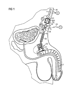
[01] The present invention relates generally to the infusion of a
substance, in particular drugs, into
a patient's body, in particular into a patient's blood circulation system or
in order to stimulate of penis
erection, by means of an at least partly implantable drug delivery system.
Back2round
[02] Intestinally implantable drug delivery systems using one or more
implantable infusion needles
are known, e.g., from WO 2010/040548 Al which is particularly designed for the
stimulation of penis
erection. According to the teaching of WO 2010/040548 Al as well as according
to the invention
which will be described hereinafter, the infusion needle is movably arranged
in a housing so that it can
be advanced in order to penetrate with a tip end thereof the housing's outer
wall. Arranging the
infusion needle in the housing prevents any fibrosis from growing into the
infusion needle. However,
frequent piercing of the same body part may cause irritation, eventually
making further piercing
difficult or even impossible. Therefore, a plurality of infusion needles or a
single laterally displaceable
infusion needle is provided so as to penetrate the housing's outer wall at
different penetration sites.
This allows for variation of the injection sites and penetration of different
injection sites at different
times, thereby giving the human tissue time to recover from the piercing by
the infusion needle. A
drive unit is provided for advancing and retracting as well as for laterally
displacing the infusion
needle or needles accordingly. A part of the drive unit may be provided for
implantation remote from
the injection area and may comprise a pull wire to cause movement of the
infusion needle upon
pulling the remote end of the wire. More specifically, pulling the wire may
cause the tip end of the
infusion needle or needles to displace laterally from a first to a second
penetration site. A single
pulling wire may be sufficient to cause movement of the infusion needle in one
direction, whereas a
spring element urges the infusion needle back to a starting position, or two
pulling wires may be
provided to move the infusion needle back and forth. A further pulling wire
may be arranged to
advance or retract the infusion needle and, again, a spring element may be
provided to urge the
infusion needle back to a starting position. The system may further comprise
one or more electric
motors inside and/or outside the housing for driving the drive unit or parts
of the drive unit, such as the
wire or wires, and may further comprise at least one reservoir adapted for
implantation inside the
patient's body and being in fluid connection with the infusion needle or
needles so as to supply to the
infusion needle the substance to be injected. Also, a pump, which is also
adapted for implantation
inside the patient's body, may be provided to advance the substance from the
reservoir to the infusion
needle or needles.
[03] As set out above, in WO 2010/040548 Al as well as according to the
disclosure, the drive unit
is configured to advance and retract the infusion needle or needles. In WO
2010/040548 Al, this is
CA 03228283 2024-02-05
WO 2023/031062 2 PCT/EP2022/073856
generally achieved by mounting the infusion needle in a slidable manner and
urge it back into a rest
position by means of a return spring. However, there is no specific disclosure
in WO 2010/040548 Al
of how the drive unit needs to be configured in order to achieve this. As
further set out above, in WO
2010/040548 Al as well as according to the disclosure, the drive unit is
configured to laterally
displace the tip ends of an infusion needle to different penetration sites or
to actuate different ones of a
plurality of infusion needles. In WO 2010/040548 Al, this is generally
achieved by mounting the
infusion needle or needles on a movable carriage, such as a turntable and/or a
slide. However, again,
there is no specific disclosure in WO 2010/040548 Al of how the drive unit
needs to be configured in
order to achieve this.
[04] It is therefore an object of the present disclosure to provide an
improved drive unit for moving
the infusion needle or needles, such as movement thereof in the advancing or
retracting direction, in
the lateral displacement direction or in both the advancing or retracting
direction and the lateral
displacement direction.
[05] As also set out above, in WO 2010/040548 Al as well as according to the
disclosure, there
may be provided more than one infusion needle. In WO 2010/040548 Al a valve is
used to distribute
the substance to be injected to individual ones of the plurality of infusion
needles. This requires
actuation of the valve and, therefore, increases the complexity of operating
the system.
[06] It is therefore another object of the present disclosure to facilitate
the manner of supplying the
substance to be injected to individual infusion needles where the system
comprises a plurality of
infusion needles.
Summary
[07] Accordingly, the at least partly implantable system for injecting a
substance into a patient's
body according to the present disclosure comprises:
- a housing adapted for implantation inside the patient's body, the housing
having an outer wall
with a penetration area,
- at least one infusion needle disposed in the housing, and
- a drive unit arranged for advancing and retracting the infusion needle or
needles in opposite
advancing and retracting directions so that a tip end thereof penetrates, upon
advancement, said
penetration area so as to allow for injecting the substance through the
penetration area via the needle
or needles.
[08] In this context, penetration of the penetration area by the tip end upon
advancement of the
infusion needle does not necessarily mean that, prior to such advancement, the
tip end resides inside
CA 03228283 2024-02-05
3
WO 2023/031062 PCT/EP2022/073856
the housing spaced apart from the internal side the housing's outer wall.
Rather, the infusion needle
may even extend with its tip end into the outer wall prior to its advancement
and, upon advancement,
penetrate the wall so as to extend from the external side of the wall. This is
at least an option in those
embodiments where the infusion needle is not displaced laterally between
successive injection cycles.
[09] Also, while the penetration area may preferably be formed from a membrane
which may be
made of a material that can be easily penetrated by the infusion needle, in
particular of an elastomeric
polymer material, such as silicone, in some instances the penetration area may
simply be a hole in the
wall through which the needle can be advanced from inside of the housing or
casing to the outside
thereof, i.e. only the hole needs to be penetrated, rather than a membrane
closing such hole.
[010] According to a first aspect of the present disclosure, the system may
further comprise a needle
cooperating member arranged to cooperate with the at least one infusion needle
upon the advancing or
retracting of the at least one infusion needle and a cross guide to which the
needle cooperating member
is coupled so as to be movable into different positions in a displacement
direction which is different to
the advancing and retracting directions. Thus, advancing or retracting the
infusion needle may involve
prior lateral displacement of the needle cooperating member along the cross
guide to different
injection site positions.
[011] Preferably, the cross guide is fixedly held between two opposing fixing
points in order to
provide a structure which is sufficiently stiff to ensure proper alignment of
the needle cooperating
member relative to the injection sites independent of the needle cooperating
member's position on, or
relative to, the cross guide. To this end, the cross guide may comprise a
shaft on which the needle
cooperating member is slidably mounted.
[012] The cross guide preferably extends in a displacement direction that is
perpendicular to the
advancing and retracting directions of the needle or needles, but may
alternatively extend in a
direction that is inclined relative to the advancing and retracting directions
of the needle or needles if
the space where the housing is to be implanted in the patient's body so
requires.
[013] Preferably, the system comprises a translating frame arranged to move in
the advancing and
retracting directions of the needle or needles, wherein the cross guide is
fixed to the translating frame
so as to move together with the translating frame. This way, once the needle
cooperating member has
been brought in a desired position relative to the cross guide, it may be
moved in the advancing and
retracting directions of the needle or needles so as to advance or retract the
needle or needles.
Preferably the arrangement is such that a single needle is advanced or
retracted upon movement of the
translating frame.
CA 03228283 2024-02-05
4
WO 2023/031062 PCT/EP2022/073856
[014] Where the at least one infusion needle comprises an array of infusion
needles, the needle
cooperating member is preferably arranged to cooperate with a respective one
infusion needle of the
array of infusion needles at a time.
[015] More specifically, the needle cooperating member may be arranged for
acting on the array of
infusion needles so as to advance or retract, depending on its position
relative to the cross guide, the
respective one infusion needle. To this end, the needle cooperating member may
be separate from the
array of infusion needles. That is, in a rest position, the needle cooperating
member may be
disengaged from the infusion needles and, upon movement of the translating
frame, it may engage the
respective one of the infusion needles. In one embodiment, the infusion
needles of the array of
infusion needles may be mounted in a mounting block so as to be slidable in
the advancing and
retracting directions, wherein the needle cooperating member is preferably
arranged to advance the
respective one infusion needle by pushing it in the advancing direction.
[016] In a particular embodiment, the needle cooperating member may comprise a
needle driver part
and a positioning part, wherein the needle driver part and the positioning
part are arranged to
disengage from each other when the translating frame moves in the advancing
direction. In this case, a
secondary cross guide member may be arranged in parallel to the cross guide,
wherein the positioning
part is movably, preferably slidably, mounted on the main secondary cross
guide member and the
needle driver part is movably, preferably slidably, mounted on the (main)
cross guide.
[017] Preferably, the arrangement is such that, when the positioning part and
the needle driver part
are engaged, the positioning part may be moved along the secondary cross guide
member in the
displacement direction, thereby moving the needle driver part along the main
cross guide also in the
displacement direction into a desired position, and, when the needle driver
part has been positioned,
the aforementioned translating frame may be moved in the advancing or
retracting direction so that the
needle driver part and the positioning part disengage from each other and so
that the needle driver part
may cooperate with the respective one infusion needle of the array of infusion
needles.
[018] A displacement cable, which will be described in further detail
hereinafter, may be provided
for pulling the needle cooperating member along the cross guide in the
displacement direction and
may be connected to the positioning part of the needle cooperating member.
[019] Where the at least one infusion needle comprises only a single infusion
needle, the single
infusion needle may be attached to the needle cooperating member so as to be
movable in the
displacement direction together with the needle cooperating member. The single
infusion needle may
be welded or potted to the needle cooperating member so as to securely hold
the infusion needle in
place.
CA 03228283 2024-02-05
WO 2023/031062 PCT/EP2022/073856
[020] The single infusion needle may have a curved section by which it is
attached to the needle
cooperating member. This may facilitate mounting of the infusion needle at a
correct position of the
needle cooperating member when the system is being assembled. More
specifically, the curved section
may be fixedly held in a correspondingly curved recess of the needle
cooperating member. The curved
recess provides a counter-force to forces acting on the needle when the needle
is advanced to pierce
with its front end through the penetration area in the wall of the housing.
[021] Also, a needle-reinforcing tube may be placed around the single infusion
needle to help
minimize any deflection of the infusion needle when penetrating the
penetration area of the housing's
wall.
[022] Finally, a tubing for supplying the substance to be injected through the
single infusion needle
may be connected to an end of the single infusion needle and looped inside the
housing to allow the
tubing a required range of motion.
[023] At least one motor may be provided, such as a first motor for advancing
and/or retracting the
needle or needles in opposite advancing and retracting directions and a second
motor for displacing the
needle or needles or the needle cooperating member in a different lateral
displacement direction.
Alternatively, two motors may be provided for, in cooperation, advancing
and/or retracting the needle
or needles in the opposite advancing and retracting directions and for
displacing the needle or needles
or the needle cooperating member in the different lateral displacement
direction.
[024] The motor or motors may be arranged within the housing in which the
needle or needles are
arranged. However, depending on the space that is available for implanting the
housing within the
patient's body, it may be desirable to keep the housing small. In that case,
one or more pull cables may
be provided to extend from one or more motors, which are remotely arranged
inside or even outside
the patient's body, into the housing in order to transfer kinetic energy into
the housing for moving the
needles or needles that are arranged in the housing. Also, one or more cables
or belts may be provided
inside the housing to transmit energy between components that are arranged
inside the housing.
[025] In all embodiments where a motor or cable is arranged to advance the
infusion needle or
needles in the advancing direction and, e.g., resilient means, such as a
spring element, are provided for
urging the needle or needles back into a rest position, the arrangement may
likewise be opposite such
that the motor or cable is arranged to retract the infusion needle or needles
into the rest position and,
e.g., resilient means, such as a spring element, are provided for advancing
the needle or needles into an
operating position.
[026] In all embodiments where a cable is employed, the cable is preferably a
Bowden cable so that
it can transmit pulling forces while being bendable. This is particularly
advantageous in situations
CA 03228283 2024-02-05
WO 2023/031062 6 PCT/EP2022/073856
where a part of the drive unit is remote from the housing and where the cable
extends into the housing
from a remotely arranged motor.
[027] While a cable is typically understood as comprising a coated set of
wires, a cable in the sense
of the present disclosure may comprise one or more wires, uncoated or
preferably coated, such as a
single uncoated wire, a single coated wire, a set of uncoated wires, a set of
coated wires, or a coated
set of wires. The wires are preferably made of metal, but may alternatively be
made or comprise one
or more polymer wires.
[028] As mentioned before, the system may comprise a displacement cable or a
displacement belt for
pulling the needle cooperating member along the cross guide in the
displacement direction.
[029] In a first embodiment, a tensioning spring may be arranged to provide a
counter-force
counteracting the pulling force of the displacement cable that may be acting
on the needle cooperating
member. The tensioning spring thus helps to hold the needle positioning member
in position relative to
the cross guide. Preferably, the counter-force provided by the tensioning
spring is strong enough to
move the needle cooperating member in a direction opposite the displacement
direction when there is
no pulling force of the displacement cable acting on the needle cooperating
member. That is, when,
after a certain number of injections, the needle cooperating member has been
displaced step by step
relative to the cross guide so that it has reached a final position, the
pulling force of the displacement
cable may be released so that the counter-force of the tensioning spring
causes the needle cooperating
member to return to a starting position.
[030] It is advantageous when the tensioning spring is designed as a constant-
force tensioning
spring. This way, the pulling force required to move the needle cooperating
member along the cross
guide, and thus the power provided by an associated motor, is constant
independent of the position of
the needle cooperating member relative to the cross guide. For instance, the
tensioning spring may
comprise a metal band which winds on itself when it is not tensioned. One end
of the metal band may
be attached to a reel and the other end may be connected to the needle
cooperating member. Then,
when the needle cooperating member is pulled step by step along the cross
guide with the aid of the
displacement cable, the tensioning spring creates a constant counter-force.
When the pulling force of
the displacement cable is released, the tensioning spring winds automatically
back onto the reel,
thereby pulling the needle cooperating member back into its starting position.
Preferably, the
tensioning spring provides a tensioning force of between 0.5 N and 2 N,
preferably between 0.8 N and
1.2 N, most preferably about 1 N.
[031] In a second embodiment, the displacement cable or displacement belt may
be arranged for
pulling the needle cooperating member along the cross guide in opposite first
and second displacement
directions. A tensioning spring as described above is not required in this
case because the needle
CA 03228283 2024-02-05
7
WO 2023/031062 PCT/EP2022/073856
cooperating member may be returned to its starting position by means of the
displacement cable. In
this case, a first wheel and a second wheel may be provided, the first wheel
having a first axis of
rotation and the second wheel having a second axis of rotation in parallel to
and spaced apart from the
first axis, wherein the displacement cable or displacement belt winds around
the first and second
wheels.
[032] Preferably, the displacement cable or displacement belt is endless. For
instance, it may be
provided in the form of a loop extending from the first wheel to the second
wheel, winding around the
second wheel by 180 or preferably ¨ in order to prevent sliding of the cable
or belt ¨ by 180 and a
number of additional complete revolutions, extending back from the second
wheel to the first wheel,
and winding around the first wheel by 180 or ¨ again ¨ preferably by 180 and
a number of additional
complete revolutions. Then, the needle cooperating member moves in the first
and second
displacement direction depending on the direction of rotation of the first and
second wheels.
[033] A tensioning element may be provided to create a tensioning force on the
displacement cable
or displacement belt in a direction transverse to a longitudinal axis of the
displacement cable or
displacement belt so as to reduce any slack in the displacement cable or
displacement belt.
[034] A motor may be arranged inside or even outside the housing to provide
power for rotating the
first or second wheel. However, as mentioned, when the space for implantation
is limited and,
therefore, the housing must be kept small so that a motor cannot be fitted
into the housing, it may be
preferable to arrange a drive cable to rotate the first or second wheel, the
drive cable accordingly
extending out of the housing to a remote motor. In this context, the drive
cable may connect to one of
the first and second wheels and wind on and off the first or second wheel or
around the first or second
wheel.
[035] Alternatively, at least one of the first and second wheels may be
mounted on a drive shaft so as
to rotate by rotation of the drive shaft and the drive cable may connect to
the drive shaft in order to
drive the drive shaft. In this case, a third wheel may be mounted on the drive
shaft and the drive cable
may wind on and off the third wheel or around the third wheel.
[036] In the case where the drive cable is arranged to wind on and off the
first or second wheel or on
and off the third wheel, the drive cable may be attached to the respective
wheel with one end of the
drive cable so that the drive cable unwinds and a section of the drive cable
moves out of the housing
when the cable is being pulled in a first direction, wherein a tensioning
spring is arranged so as to pull
the drive cable into an opposite second direction back into the housing onto
the respective wheel. In
the alternative case where the drive cable is arranged to wind around the
first or second wheel or
around the third wheel, the drive cable may be arranged so that, when the
drive cable is being pulled,
CA 03228283 2024-02-05
WO 2023/031062 8 PCT/EP2022/073856
one section of the drive cable moves into the housing while another section of
the drive cable moves
out of the housing.
[037] In all embodiments, a first alignment structure may be arranged on the
needle cooperating
member and a second alignment structure may be arranged stationary so that the
first and second
alignment structures engage with each other and define different rest
positions for the needle
cooperating member when the needle cooperating member is moved along the cross
guide into
different positions. This arrangement supports exact positioning of the needle
cooperating member.
[038] In a preferred embodiment, the first alignment structure may be a leaf
spring and the second
alignment structure may comprise a plurality of stationary detents or
protrusions arranged to cooperate
with the leaf spring or, alternatively, the first alignment structure may
comprise the plurality of detents
or protrusions and the second alignment structure comprises one or more
stationary leaf springs
arranged to cooperate with the detents or protrusions. Thus, when the needle
cooperating member is
moved relative to the cross guide in the displacement direction from one
position to the next position,
the leaf spring is urged backwards to disengage from the detents or
protrusions and then snaps forward
again in order to reengage with one or more neighboring detents or
protrusions.
[039] According to a second aspect of the present disclosure, the system
comprises at least one linear
bearing, preferably two parallel linear bearings, and a translating frame
arranged to move along the
linear bearing or bearings in the advancing and retracting directions of the
at least one infusion needle
so as to advance or retract or both advance and retract the infusion needle or
needles by respective
movement of the translating frame. Most preferably, the cross guide described
above to which the
needle cooperating member is coupled may be fixed to the translating frame so
that it can be moved
together with the translating frame in the needle advancing and retracting
directions. Providing two
parallel linear bearings increases the stability and accuracy of the system.
The two linear bearings
preferably take the form of two parallel shafts to which the translating frame
is slidably mounted.
[040] Further at least one return spring may be arranged to urge the
translating frame into a rest
position. For instance, the at least one return spring may comprise a coil
spring arranged around one
linear bearing or, more preferably, two coil springs arranged around
respective ones of two parallel
linear bearings.
[041] The drive unit may comprise an advancement cable which is arranged so
that pulling the
advancement cable causes the advancing or retracting of the at least one
infusion needle. For example,
the advancement cable may be arranged to move the translating frame along the
at least one linear
bearing in the advancing and retracting directions, thereby advancing and/or
retracting the infusion
needle or needles. The advancement cable may be guided through the wall of the
housing towards a
CA 03228283 2024-02-05
9
WO 2023/031062 PCT/EP2022/073856
motor which is arranged remote from the housing at a location outside the
patient or more preferably
at a location somewhere inside the patient.
[042] According to a third aspect of the present disclosure, the advancement
cable may form part of
a block-and-tackle setup. This reduces the amount of power that is needed to
advance the needle or
needles through the penetration area in the wall of the housing. Accordingly,
the motor for driving the
advancement cable may be relatively small.
[043] In the case that the advancement cable is arranged to move the above-
mentioned translating
frame along the above-mentioned linear bearing or bearings in the advancing
and retracting directions,
the block-and-tackle setup may comprise at least one first pulley, preferably
two first pulleys, fixed to
the translating frame so as to move together with the translating frame and at
least one second pulley,
preferably two second pulleys, fixed to the housing so as to be stationary. In
addition, one end of the
advancement cable is either fixed to the housing or to the translating frame.
Thus, when the
advancement cable is fixed with one of its ends to the housing and the
advancement cable is being
pulled so as to move the translating frame, it winds along the first pulley
which moves along with the
translating frame, thereby dividing the pulling force necessary for moving the
translating frame by 2.
By providing two first and two second pulleys, the pulling force may be
further divided in half once
again.
[044] According to a fourth aspect of the present disclosure, the drive unit
may comprise a combined
advancement and displacement cable which is arranged so that pulling the
advancement and
displacement cable allows for causing both the advancing or retracting of the
at least one infusion
needle and the displacement of the at least one infusion needle in a
displacement direction which is
different to the advancing and retracting directions. For example, a first
actuator may be attached to a
first end of the advancement and displacement cable and a second actuator may
be attached to a
second end of the advancement and displacement cable, wherein the first
actuator is arranged so as to
allow pulling and moving the advancement and displacement cable in a first
pulling direction and the
second actuator is arranged so as to allow pulling and moving the advancement
and displacement
cable in a second pulling direction opposite to the first pulling direction.
[045] The arrangement may be such that simultaneous actuation of the first and
second actuators so
as to move the advancement and displacement cable in opposite first and second
pulling directions
causes the advancing or retracting of the at least one infusion needle.
[046] In this case, when the advancement and displacement cable is arranged to
move the above-
mentioned translating frame along the above-mentioned linear bearing or
bearings in the advancing
and retracting directions, movement of the advancement and displacement cable
in opposite first and
second pulling directions may cause the translating frame to move along the
linear bearing or bearings.
CA 03228283 2024-02-05
WO 2023/031062 10 PCT/EP2022/073856
This may be achieved, for example, by means of at least two first pulleys
fixed to the housing so as to
be stationary, wherein the advancement and displacement cable is guided over
one of the two first
pulleys fixed to the housing, further to the translating frame and further
over the other one of the two
first pulleys fixed to the housing. Thus, when the opposite ends of the
advancement and displacement
cable are pulled in opposite first and second pulling directions over the same
distance, the translating
frame is pulled along the linear bearing or bearings in a direction towards
the two first pulleys, such as
in the advancing direction of the infusion needle or needles. While the
aforementioned block-and-
tackle setup may likewise be provided for the advancement and displacement
cable, this is not so
important in this case, because here two motors instead of only one motor may
be used, one at each
end of the advancement and displacement cable, so that twice the amount of
power is available. Again,
the aforementioned return spring may be arranged to urge the translating frame
towards a rest position
so that, when the pulling force on the advancement and displacement cable is
reduced, the return
spring will cause automatic movement of the translating frame back into the
rest position.
[047] The arrangement may further be such that actuation of any one of the
first and second
actuators so as to move the advancement and displacement cable in the first or
second pulling
direction, while the respective other one of the first and second actuators is
not caused to move the
advancement and displacement cable, causes the displacement of the at least
one infusion needle in the
displacement direction.
[048] In this case, when the system comprises the above-mentioned needle
cooperating member to
which the at least one infusion needle is attached and the above-mentioned
cross guide to which the
needle cooperating member is coupled, the advancement and displacement cable
may be connected to
the needle cooperating member so as to pull and move the needle cooperating
member along the cross
guide into different positions in the displacement direction. This may be
achieved, for example, by
means of at least two second pulleys fixed to the translating frame on opposed
sides of the needle
cooperating member, wherein the advancement and displacement cable is guided
over the two second
pulleys. Thus, when the advancement and displacement cable is pulled in the
one or in the other
pulling direction, the needle cooperating member is accordingly pulled along
the cross guide towards a
respective one of the two second pulleys, namely in a displacement direction
of the infusion needle or
needles.
[049] In one embodiment, the advancement and displacement cable may comprise
two separate cable
sections, each cable section having one end thereof connected to the needle
cooperating member.
However, the advancement and displacement cable may alternatively be
continuous with a central
portion thereof being fixedly connected to the needle cooperating member.
CA 03228283 2024-02-05
WO 2023/031062 11 PCT/EP2022/073856
[050] As becomes clear from the foregoing, in this fourth aspect, two motors
may be arranged for, in
cooperation, advancing or retracting the at least one infusion needle in the
advancing or retracting
direction and, individually, displacing the needle cooperating member in
respectively opposite
displacement directions.
[051] In particular, also in this fourth aspect, the at least one infusion
needle may comprise only a
single infusion needle attached to the needle cooperating member so as to be
movable in the
displacement direction together with the needle cooperating member. Again, the
single infusion needle
may be welded or potted to the needle cooperating member and may have a curved
section by which it
is attached to the needle cooperating member, wherein the curved section may
be fixedly held in a
correspondingly curved recess of the needle cooperating member. Also, a needle-
reinforcing tube may
be placed around the single infusion needle to help minimize any deflection of
the infusion needle
when penetrating the penetration area of the housing's wall, and a tubing for
supplying the substance
to be injected through the single infusion needle may be connected to an end
of the single infusion
needle and looped inside the housing to allow the tubing a required range of
motion.
[052] According to a fifth aspect of the present disclosure, the at least one
infusion needle may have
a tubular needle body with a tip end, an injection port arranged at the tip
end so as to allow for
injecting the substance via the at least one infusion needle, a feeding port
arranged distant from the tip
end so as to allow for receiving the substance to be injected and a needle
lumen inside the tubular
needle body connecting the injection port with the feeding port, wherein the
feeding port is a side port
which is arranged on a side of the tubular needle body. Thus, according to
this aspect, the substance to
be injected is fed sideways into the needle body. This way, the supply lumen
is not in conflict with the
rear end of the needle, which end may be used and specifically adapted for
moving the infusion needle
in the advancing or retracting direction. While this aspect is certainly
applicable in cases where only a
single infusion needle is present so that only a single supply lumen is
required, this aspect may
advantageously be employed also in a system which comprises a plurality of
infusion needles. In
general, in cases where a plurality of needles is provided, the infusion
needles may be spaced apart
from each other by a distance of between 1 mm and 2 mm, preferably by a
distance of 1.5 mm.
[053] In either case, the system may comprise an internal reservoir inside the
housing which is
arranged for holding the substance to be injected, wherein, when the infusion
needle is in an advanced
position in which it penetrates the penetration area, the feeding port is
positioned inside the internal
reservoir and the injection port is positioned outside the housing.
Accordingly, in this position the
substance, such as an infusion liquid, may enter the infusion needle through
the feeding port arranged
on the side of the tubular needle body and, when an appropriate pressure is
applied on the substance in
the internal reservoir, the substance will flow from the internal reservoir
through the feeding port,
needle lumen and injection port into the patient. In the case of a plurality
of infusion needles, they may
CA 03228283 2024-02-05
WO 2023/031062 12 PCT/EP2022/073856
be arranged so that each of the infusion needles may be advanced individually
into a position in which
it penetrates the penetration area with its respective feeding port positioned
inside the internal
reservoir and its respective injection port positioned outside the housing.
[054] Preferably, the penetration area may comprise a septum and the internal
reservoir may be
arranged within the septum such that, when the infusion needle is in a
retracted position, the feeding
port is outside the internal reservoir and inside the septum. This way, the
feeding port is hermetically
closed by the material of the septum when the infusion needle is not in use
and retracted.
Alternatively, the dimension of the internal reservoir inside the septum may
be such that the feeding
port is positioned inside the internal reservoir when the infusion needle is
in the retracted position.
This may be advantageous in order to ensure that the needle lumen is filled
with substance from the
internal reservoir before the infusion needle is moved from its retracted
position to its advanced
position. Again, in the case of a plurality of infusion needles, each of the
infusion needles is arranged
in this way, preferably in a side-by-side arrangement.
[055] Further preferably, also the injection port at the tip end of the
infusion needle or needles may
be arranged inside the septum when the infusion needle is in the retracted
position. This way, the
injection port is safely protected. In this retracted position, the injection
port may be arranged inside
the septum and outside the internal reservoir. This way, again, also the
injection port is hermetically
closed by the material of the septum when the infusion needle is not in use
and retracted. Furthermore,
such arrangement increases the stability of the infusion needle and gives some
guidance to the needle
movement. Alternatively, the injection port may be arranged inside the septum
and inside the internal
reservoir when the infusion needle is in the retracted position. Again, this
may be advantageous in
order to ensure that the needle lumen is already filled with substance from
the internal reservoir before
the infusion needle is moved from its retracted position to its advanced
position.
[056] As regards a supply lumen for supplying the substance to be injected to
the internal reservoir,
in the cases where the system comprises the above-mentioned one or more linear
bearings and
translating frame arranged to move along the linear bearings in the advancing
and retracting directions
so as to advance and/or retract the infusion needle by respective movement of
the translating frame,
the supply lumen may be arranged so as to run along an inner lumen of the
linear bearing. This way
the overall size of the housing may be kept small. The inner lumen preferably
connects directly to the
aforementioned internal reservoir.
[057] Preferably, also the injection port of the infusion needle is designed
as a side port arranged on
a side of the tubular needle body. Thus, the infusion needle may be closed at
its tip end and the
laterally arranged injection port is used for delivery of the drug into the
particular body part.
Therefore, the infusion needle will not cut out any material but will simply
divide it during
CA 03228283 2024-02-05
WO 2023/031062 13
PCT/EP2022/073856
penetration. Thus, when the infusion needle penetrates any material, such as
fibrosis and/or the
septum, which may be in the form of a self-sealing penetration membrane, there
will be no material
entering and blocking the drug delivery passageway.
[058] In all embodiments, the maximum size of the housing is 30 mm x 40 mm x 6
mm.
Communication
[059] According to a further aspect of the present disclosure, security of the
system against
fraudulent third-party intervention may be increased. This is particularly
important in the context of
wireless communication, which can easily be intercepted and then misused by
third parties.
Accordingly, the system is preferably configured such that at least one of:
- wireless communication from or to, or both from and to, a controller of
the system is encrypted,
- data transmitted by a controller via wireless communication is signed,
and
- authentication of a user of the system involves input of authentication
data of the patient.
[060] Preferably, the encrypted wireless communication includes encryption
with a public key and
decryption with a private key, such as the well-known RSA encryption. Other
encryption methods
may likewise be implemented. Preferably, the security level is further
increased in that the private key
may be a combined key derived by combining at least a first key and a second
key.
[061] Similarly, as regards the signing of the data transmitted wirelessly by
a controller, such as by
the aforementioned external controller or remote controller to the internal
controller, the signing may
involve a private key, whereas subsequent verification of the signed data may
involve a corresponding
public key.
[062] Preferably, data communication involves both an encryption and a
signature. The RSA
encryption technology allows for both, encrypting the data and adding a
digital signature to the data.
For the encryption/decryption process, the sender uses a public key of the
recipient for encrypting the
data and the recipient uses his private key for subsequently decrypting the
data, whereas for the
signing/authentication process, the sender uses his private key to sign the
(encrypted) data and the
recipient uses the sender's public key to authenticate the signature.
[063] As regards the authentication of a user which involves input of
authentication data of the
patient, the system may comprise a verification unit which is configured to
obtain the authentication
data of the patient. For instance, the verification unit may comprise at least
one of a fingerprint reader,
a retina scanner, a camera, a graphical user interface for inputting a code,
and a microphone. Only
CA 03228283 2024-02-05
WO 2023/031062 14 PCT/EP2022/073856
after a positive verification by the verification unit will certain functions
of the system be enabled. For
instance, the positive verification may enable the controller to process
certain data or may open a
communication channel between two controllers of the system, such as a
wireless communication
channel.
[064] Alternatively or in addition, the system may comprise a sensation
generator for generating a
sensation which is detectable by a sense of the patient. In this course, the
patient may input into the
system authentication data which relate to what the patient has sensed. Then,
the authentication of the
user may involve a verification by the verification unit that the
authentication data input by the user
matches data from the sensation generator which relate to the sensation
generated by the sensation
generator. Again, only after a positive verification by the verification unit
will certain functions of the
system be enabled. For instance, the positive verification may enable the
controller to process certain
data or may open a communication channel between two controllers of the
system, such as a wireless
communication channel.
[065] In this context, the sensation generator may be configured to generate
as the sensation
detectable by the sense of the patient at least one of:
- a vibration, which may include e.g. a fixed-frequency mechanical
vibration,
- a sound, which may include e.g. a superposition of fixed-frequency
mechanical vibrations,
- a photonic signal, which may include e.g. a non-visible light pulse, such
as an infrared pulse,
- a light signal, which may include e.g. a visual light pulse,
- an electrical signal, which may include e.g. an electrical current pulse,
and
- a heat signal, which may include e.g. a thermal pulse.
General Communication Housing
[066] Further, an external device configured for the communication with the
implantable medical
device when implanted in a patient is provided, the external device
comprising: a display device and a
housing unit configured to mechanically and disconnectably connect to the
display device, wherein the
housing comprises a first communication unit for receiving communication from
the display device
and a second communication unit for wirelessly transmitting communication to
the implantable
medical device.
[067] According to one embodiment, the external device comprises a handheld
electronic device.
CA 03228283 2024-02-05
WO 2023/031062 15 PCT/EP2022/073856
[068] According to one embodiment, the external device is configured for
communicating with the
implantable medical device for changing the operational state of an
implantable medical device. The
advantage of the embodiment is that the operational state of the implantable
medical device can be
changed remotely.
[069] According to one embodiment, the first communication unit is a wireless
communication unit
for wireless communication with the display device. The advantage of the
embodiment is that the
display device can be communicated without the need of electric wires.
[070] According to one embodiment, the first communication unit is configured
to communicate
wirelessly with the display device using a first communication frequency and
the second
communication unit is configured to communicate wirelessly with the
implantable medical device
using a second communication frequency, wherein the first and second
communication frequencies are
different. The advantage of the embodiment is that the likelihood of
interferences is reduced.
[071] According to one embodiment, the second communication unit is configured
to communicate
wirelessly with the implantable medical device using electromagnetic waves at
a frequency below 100
kHz.
[072] According to one embodiment, the second communication unit is configured
to communicate
wirelessly with the implantable medical device using electromagnetic waves at
a frequency below 40
kHz. The advantage of the embodiment is that titanium, which is commonly used
for medical devices,
is transparent for electromagnetic waves below 40 kHz.
[073] According to one embodiment, the first communication unit is configured
to communicate
wirelessly with the display device using electromagnetic waves at a frequency
above 100 kHz. The
advantage of the embodiment is that the frequency spectrum below 100 kHz
remains noise free for the
communication with the medical implantable device.
[074] According to one embodiment, the first communication unit is configured
to communicate
wirelessly with the display device using a first communication protocol and
the second
communication unit is configured to communicate wirelessly with the
implantable medical device
using a second communication protocol, wherein the first and second
communication protocols are
different. The advantage of the embodiment is that the protocol can be
independently chosen for the
communication of the first and second communication units, depending on which
protocol suits the
needs of the communication units better.
[075] According to one embodiment, the housing unit comprises a first antenna
configured for
wireless communication with the display device and a second antenna configured
for wireless
CA 03228283 2024-02-05
WO 2023/031062 16 PCT/EP2022/073856
communication with the implantable medical device. The advantage of the
embodiment is that the
antenna can be independently chosen for the communication of the first and
second communication
units, depending on which antenna suits the needs of the communication units
better.
[076] According to one embodiment, the first communication unit is a wire-
based communication
unit for wire-based communication with the display device. The advantage of
the embodiment is that
the communication of the first communication unit is reliable and secure.
[077] According to one embodiment, the display device comprises a first
communication unit for
communication with the housing unit and a second communication unit for
wireless communication
with a second external device. The advantage of the embodiment is that
communication with an
additional external device becomes possible, thereby introducing redundancy
and reliability.
[078] According to one embodiment, the second communication unit of the
display device is
configured for communicating with the second external device over the
internet. The advantage of the
embodiment is that the display device can communicate with devices far away.
[079] According to one embodiment, the first communication unit of the display
device is a wireless
communication unit for wireless communication with the housing unit. The
advantage of the
embodiment is that the communication unit can be connected to the housing unit
without the use of
wires.
[080] According to one embodiment, the first communication unit of the display
device is configured
to communicate wirelessly with the housing unit using a first communication
frequency and the
second communication unit of the display device is configured to communicate
wirelessly with the
second external device using a second communication frequency, wherein the
first and second
communication frequencies are different. The advantage of the embodiment is
that the likelihood of
interferences is reduced and the signal to interference and noise ratio is
increased.
[081] According to one embodiment, the first communication unit of the display
device is configured
to communicate wirelessly with the housing unit using a first communication
protocol and the second
communication unit of the display device is configured to communicate
wirelessly with the second
external device using a second communication protocol, wherein the first and
second communication
protocols are different. The advantage of the embodiment is that the protocol
can be independently
chosen for the communication of the first and second communication units,
depending on which
protocol suits the needs of the communication units better.
[082] According to one embodiment, the display device comprises a first
antenna configured for
wireless communication with the housing and a second antenna configured for
wireless
CA 03228283 2024-02-05
WO 2023/031062 17 PCT/EP2022/073856
communication with the second external device. The advantage of the embodiment
is that the antenna
can be independently chosen for the communication of the first and second
communication units,
depending on which antenna suits the needs of the communication units better.
[083] According to one embodiment, the first communication unit is a wire-
based communication
unit for wire-based communication with the housing unit. The advantage of the
embodiment is that the
communication of the first communication unit is reliable and secure.
[084] According to one embodiment, the display device is configured to display
a user interface to
the patient. The advantage of the embodiment is that the patient can use his
familiar display device to
communicate with the housing unit.
[085] According to one embodiment, the housing unit is configured to transmit
information
pertaining to the display of the user interface to the display device. The
advantage of the embodiment
is that the patient can receive information using his familiar display device.
[086] According to one embodiment, the display device is configured to receive
from the patient
input pertaining to communication to or from the implantable medical device
and transmit signals
based on the received input to the housing unit. The advantage of the
embodiment is that the patient
can use his familiar display device to communicate with the housing unit.
[087] According to one embodiment, the display device comprises a touch screen
configured to
display the user interface and receive the input from the patient. The
advantage of the embodiment is
that the patient can use a familiar way of handling the information.
[088] According to one embodiment, the housing unit is configured to display a
user interface to the
patient. The advantage of the embodiment is that the housing unit can receive
user input.
[089] According to one embodiment, the first communication unit of the housing
unit is configured
to receive communication from the implantable medical device pertaining to
input from the patient
and wirelessly transmit signals based on the received input to the implantable
medical device, using
the second communication unit. The advantage of the embodiment is that the
housing unit acts as an
extra node in the communication between the display device and the medical
implantable device,
thereby enabling it to monitor the communication.
[090] According to one embodiment, the second communication unit of the
housing unit is
configured for wireless communication with the implantable medical device
using a standard network
protocol. The advantage of the embodiment is that the implementation of the
communication units is
cheap and the protocols are reliable.
CA 03228283 2024-02-05
WO 2023/031062 18 PCT/EP2022/073856
[091] According to one embodiment, the standard network protocol is one of the
list of: Radio
Frequency type protocol, RFID-type protocol, WLAN-type protocol, Bluetooth-
type protocol, BLE-
type protocol, NFC-type protocol, 3G/4G/5G-type protocol, and GSM-type
protocol.
[092] According to one embodiment, the second communication unit of the
housing unit comprises a
Bluetooth transceiver.
[093] According to one embodiment, the second communication unit of the
housing unit is
configured for wireless communication with the implantable medical device
using a proprietary
network protocol. The advantage of the embodiment is that the housing unit is
compatible with
implantable medical devices that use proprietary network protocols.
[094] According to one embodiment, the second communication unit of the
housing unit comprises a
UWB transceiver. The advantage is that high data rates can be communicated via
the second
communication unit.
[095] According to one embodiment, the first communication unit of the housing
unit is configured
for wireless communication with the display device using a standard network
protocol. The advantage
of the embodiment is that the implementation of the communication units is
cheap and the protocols
are reliable.
[096] According to one embodiment, the standard network protocol is an NFC-
type protocol. The
advantage of the embodiment is that the distance between the communicating
devices is limited,
thereby protecting against eavesdropping attacks.
[097] According to one embodiment, the first communication unit of the housing
unit is configured
for wireless communication with the display device using a proprietary network
protocol. The
advantage of the embodiment is that the housing unit is compatible with
implantable medical devices
that use proprietary network protocols.
[098] According to one embodiment, a communication range of the first
communication unit of the
housing unit is less than a communication range of the second communication
unit of the housing unit.
The advantage of the embodiment is that energy is saved by selecting the first
communication unit
when its range suffices.
[099] According to one embodiment, a communication range of the first
communication unit of the
display device is less than a communication range of the second communication
unit of the display
device. The advantage of the embodiment is that energy is saved by selecting
the first communication
unit when its range suffices.
CA 03228283 2024-02-05
WO 2023/031062 19 PCT/EP2022/073856
[0100] According to one embodiment, at least one of the housing unit and the
display device is
configured to allow communication between the housing unit and the display
device on the basis of a
distance between the housing unit and the display device. The advantage of the
embodiment is that the
distance is used as a safety and authorization factor.
[0101] According to one embodiment, at least one of the housing unit and the
display device is
configured to allow communication between the housing unit and the display
device on the basis of
the housing unit being mechanically connected to the display device. The
advantage of the
embodiment is that the safety against a man-in-the-middle attacks is
increased.
[0102] According to one embodiment, the housing unit is configured to allow
communication
between the housing unit and the implantable medical device on the basis of a
distance between the
housing unit and the implantable medical device. The advantage of the
embodiment is that the distance
is used as a safety and authorization factor.
[0103] According to one embodiment, the housing unit further comprises an
encryption unit
configured to encrypt communication received from the display device. The
advantage of the
embodiment is that the encrypted communication is protected against unwanted
third party access.
[0104] According to one embodiment, the housing unit is further adapted to
transmit the encrypted
communication to the implantable medical device using the second communication
unit. The
advantage of the embodiment is that the encrypted communication is protected
against unwanted third
party access.
[0105] According to one embodiment, the second communication unit of the
display device is
configured to be disabled to enable at least one of: communication between the
display device and the
housing unit, and communication between the housing unit and the implantable
medical device.
[0106] The display device in any of the embodiments described herein may be a
wearable device or a
handset. The advantage of the embodiment is that the device is mobile and can
be used where needed.
[0107] According to one embodiment, the housing unit comprises a case for the
wearable device or
handset. The advantage of the embodiment is that the wearable device or
handset can be protected
from mechanical damage.
[0108] Further, a housing unit configured for communication with the
implantable medical device
when implanted in a patient is provided, the housing unit being configured to
mechanically connect to
a display device and comprising a first communication unit for communication
with the display device
and a second communication unit for wireless communication with the
implantable medical device.
CA 03228283 2024-02-05
WO 2023/031062 20 PCT/EP2022/073856
[0109] According to one embodiment, the display device is a wearable device or
a handset and the
housing unit comprises a case for the wearable device or handset.
[0110] According to one embodiment, the first communication unit is a wireless
communication unit
for wireless communication with the display device.
[0111] According to one embodiment, the first communication unit is configured
to communicate
wirelessly with the display device using a first communication frequency and
the second
communication unit is configured to communicate wirelessly with the
implantable medical device
using a second communication frequency, wherein the first and second
communication frequencies are
different.
[0112] According to one embodiment, the housing unit is configured to transmit
information
pertaining to the display of a user interface to the display device.
[0113] According to one embodiment, the housing unit is configured to receive
patient input from the
display device.
[0114] According to one embodiment, the housing unit is configured to display
a user interface to the
patient.
[0115] According to one embodiment, the housing unit is configured to allow
communication
between the housing unit and the display device on the basis of a distance
between the housing unit
and the display device.
[0116] According to one embodiment, the housing unit is configured to allow
communication
between the housing unit and the display device on the basis of the housing
unit being mechanically
connected to the display device.
[0117] According to one embodiment, the housing unit is configured to allow
communication
between the housing unit and the implantable medical device on the basis of a
distance between the
housing unit and the implantable medical device.
[0118] According to one embodiment, the housing unit further comprises an
encryption unit
configured to encrypt communication received from the display device.
[0119] According to one embodiment, the housing unit is further adapted to
transmit the encrypted
communication to the implantable medical device using the second communication
unit.
CA 03228283 2024-02-05
WO 2023/031062 21 PCT/EP2022/073856
[0120] According to one embodiment, the minimum bounding box of the housing
unit and the display
device, when the housing is mechanically connected to the display device, is
no more than 10 %
wider, 10 % longer or 100 % higher than the minimum bounding box of the
display device.
[0121] According to one embodiment, the housing unit comprises one or more
switches configured to
be used by the patient when the housing is not mechanically connected to the
display device.
[0122] According to one embodiment, the switches are at least partly covered
by the display device,
when the display device is mechanically connected to the housing unit.
[0123] According to one embodiment, at least a part of the housing bends in
order to mechanically
connect to the display device.
[0124] According to one embodiment, at least a part of the housing is
configured to clasp the display
device.
[0125] According to one embodiment, the housing is configured to cover at
least one side of the
display device when it is mechanically connected to the display device.
[0126] According to one embodiment, the housing is configured to be
mechanically connected to the
display device by a device which is mechanically connected to the housing and
the display device.
General Security Module
[0127] Further, an implantable controller for the implantable medical device
is provided. The
implantable controller comprises a wireless transceiver for communicating
wirelessly with an external
device, a security module, and a central unit configured to be in
communication with the wireless
transceiver, the security module and the implantable medical device. The
wireless transceiver is
configured to receive communication from the external device including at
least one instruction to the
implantable medical device and transmit the received communication to the
central unit. The central
unit is configured to send secure communication to the security module derived
from the
communication received from the external device, and the security module is
configured to decrypt at
least a portion of the secure communication and/or verify the authenticity of
the secure
communication. The security module is configured to transmit a response
communication to the
central unit and the central unit is configured to communicate the at least
one instruction to the
implantable medical device, the at least one instruction being based on the
response communication or
on a combination of the response communication and the communication received
from the external
device.
CA 03228283 2024-02-05
WO 2023/031062 22 PCT/EP2022/073856
[0128] According to one embodiment, the security module comprises a set of
rules for accepting
communication from the central unit.
[0129] According to one embodiment, the wireless transceiver is configured to
be placed in an off-
mode, in which no wireless communication can be transmitted or received by the
wireless transceiver,
and wherein the set of rules comprises a rule stipulating that communication
from the central unit is
only accepted when the wireless transceiver is placed in the off-mode.
[0130] According to one embodiment, the set of rules comprises a rule
stipulating that communication
from the central unit is only accepted when the wireless transceiver has been
placed in the off-mode
for a specific time period.
[0131] According to one embodiment, the central unit is configured to verify a
digital signature of the
received communication from the external device.
[0132] According to one embodiment, the set of rules comprises a rule
stipulating that communication
from the central unit is only accepted when the digital signature of the
received communication has
been verified by the central unit.
[0133] According to one embodiment, the central unit is configured to verify
the size of the received
communication from the external device.
[0134] According to one embodiment, the set of rules comprises a rule
stipulating that communication
from the central unit is only accepted when the size of the received
communication has been verified
by the central unit.
[0135] The wireless transceiver of any of the preceding embodiments may be
configured to receive a
message from the external device being encrypted with at least a first and
second layer of encryption
and the central unit may be configured to decrypt a first layer of decryption
and transmit at least a
portion of the message comprising the second layer of encryption to the
security model. The security
module may be configured to decrypt the second layer of encryption and
transmit a response
communication to the central unit based on the portion of the message
decrypted by the security
module.
[0136] According to one embodiment, the central unit may be configured to
decrypt a portion of the
message comprising a digital signature such that the digital signature can be
verified by the central
unit.
CA 03228283 2024-02-05
WO 2023/031062 23 PCT/EP2022/073856
[0137] According to one embodiment, the central unit is configured to decrypt
a portion of the
message comprising message size information such that the message size can be
verified by the central
unit.
[0138] According to one embodiment, the central unit is configured to decrypt
a first and second
portion of the message, and the first portion comprises a checksum for
verifying the authenticity of the
second portion.
[0139] According to one embodiment, the response communication transmitted
from the security
module comprises a checksum, and the central unit may be configured to verify
the authenticity of at
least a portion of the message decrypted by the central unit using the
received checksum.
[0140] According to one embodiment, the set of rules comprises a rule related
to the rate of data
transfer between the central unit and the security module.
[0141] The security module in any of the embodiments herein may be configured
to decrypt a portion
of the message comprising a digital signature, encrypted with the second layer
of encryption, such that
the digital signature can be verified by the security module.
[0142] The central unit may be configured such that it is only capable of
decrypting a portion of the
communication received from the external device when the wireless transceiver
is placed in the off-
mode.
[0143] According to one embodiment, the central unit is only capable of
communicating the at least
one instruction to the implantable medical device when the wireless
transceiver is placed in the off-
mode.
[0144] According to one embodiment, the implantable controller is configured
to receive, using the
wireless transceiver, a message from the external device comprising a first
non-encrypted portion and
a second encrypted portion, decrypt the encrypted portion, and use the
decrypted portion to verify the
authenticity of the non-encrypted portion.
[0145] According to one embodiment, the central unit is configured to transmit
the encrypted portion
to the security module, receive a response communication from the security
module based on
information contained in the encrypted portion being decrypted by the security
module, and use the
response communication to verify the authenticity of the non-encrypted
portion.
[0146] According to one embodiment, the non-encrypted portion comprises at
least a portion of the at
least one instruction to the implantable medical device.
CA 03228283 2024-02-05
WO 2023/031062 24 PCT/EP2022/073856
[0147] The implantable controller may be configured to receive, using the
wireless transceiver, a
message from the external device comprising information related to at least
one of a physiological
parameter of the patient and a physical parameter of the implanted medical
device and use the received
information to verify the authenticity of the message.
[0148] The physiological parameter of the patient may comprise at least one
of: a temperature, a heart
rate and a saturation value.
[0149] The physical or functional parameter of the implanted medical device
may comprise at least
one of: a current setting or value of the implanted medical device, a prior
instruction sent to the
implanted medical device and an ID of the implanted medical device.
[0150] According to one embodiment, the portion of the message comprising the
information is
encrypted, and the central unit is configured to transmit the encrypted
portion to the security module
and receive a response communication from the security module based on the
information having been
decrypted by the security module.
[0151] According to one embodiment, the security module comprises a hardware
security module
comprising at least one hardware-based key. The hardware-based key may
correspond to a hardware-
based key in the external device, which may be a hardware-based key on a key-
card connectable to the
external device.
[0152] According to one embodiment, the security module comprises a software
security module
comprising at least one software-based key. The software-based key may
correspond to a software-
based key in the external device. The software-based key may correspond to a
software-based key on a
key-card connectable to the external device. The security module may in any of
the embodiments
comprise a combination of a software-based key and a hardware-based key.
[0153] In any of the preceding embodiments, the implantable controller may
comprise at least one
crypto-processor.
[0154] The wireless transceiver may in any of the embodiments be configured to
receive
communication from a handheld external device.
[0155] According to one embodiment, the at least one instruction to the
implantable medical device
may comprise an instruction for changing an operational state of the
implantable medical device.
[0156] The wireless transceiver may be configured to communicate wirelessly
with the external
device using electromagnetic waves at a frequency below 100 kHz or at a
frequency below 40 kHz.
CA 03228283 2024-02-05
WO 2023/031062 25 PCT/EP2022/073856
[0157] According to one embodiment, the wireless transceiver is configured to
communicate
wirelessly with the external device using a first communication protocol, and
the central unit is
configured to communicate with the security module using a second different
communication
protocol.
[0158] In any of the embodiments , the wireless transceiver may be configured
to communicate
wirelessly with the external device using a standard network protocol. The
standard network protocol
may be selected from a list comprising RFID-type protocols, WLAN-type
protocols, Bluetooth type
protocols, BLE-type protocols, NFC-type protocols, 3G/4G/5G-type protocols,
and GSM-type
protocols.
[0159] The wireless transceiver may in some embodiments be configured to
communicate wirelessly
with the external device using a proprietary network protocol.
[0160] According to one embodiment, the wireless transceiver comprises a UWB
transceiver.
[0161] According to one embodiment, the security module and/or the central
unit and/or the wireless
transceiver are comprised in the controller.
[0162] The external unit in any of the embodiments herein may be a wearable
device or a handset.
The advantage of the embodiment is that the device is mobile and can be used
where needed.
[0163] Further, the implantable medical device may comprise a receiving unit.
The implantable
medical device comprises at least one coil configured for receiving
transcutaneously transferred
energy, a measurement unit configured to measure a parameter related to the
energy received by the
coil, a variable impedance electrically connected to the coil, a switch placed
between the variable
impedance and the coil for switching off the electrical connection between the
variable impedance and
the coil. The implantable medical device further comprises a controller
configured to control at least
one of the variable impedance for varying the impedance and thereby tune the
coil based on the
measured parameter, and the switch for switching off the electrical connection
between the variable
impedance and the coil in response to when the measured parameter exceeds a
threshold value.
[0164] According to one embodiment, the controller is configured to vary the
variable impedance in
response to when the measured parameter exceeds a threshold value.
[0165] According to one embodiment, the measurement unit is configured to
measure a parameter
related to the energy received by the coil over a time period.
[0166] According to one embodiment, the measurement unit is configured to
measure a parameter
related to a change in energy received by the coil.
CA 03228283 2024-02-05
WO 2023/031062 26 PCT/EP2022/073856
[0167] According to one embodiment, the first switch is placed at a first end
portion of the coil, and
the implantable medical device further comprises a second switch placed at a
second end portion of
the coil such that the coil can be completely disconnected from other portions
of the implantable
medical device.
[0168] According to one embodiment, the receiving unit is configured to
receive transcutaneously
transferred energy in pulses according to a pulse pattern, and the measurement
unit is configured to
measure a parameter related to the pulse pattern.
[0169] According to one embodiment, the controller is configured to control
the variable impedance
in response to when the pulse pattern deviates from a predefined pulse
pattern.
[0170] According to one embodiment, the controller is configured to control
the switch for switching
off the electrical connection between the variable impedance and the coil in
response to the pulse
pattern deviating from a predefined pulse pattern.
[0171] According to one embodiment, the measurement unit is configured to
measure a temperature
in the implantable medical device or in the body of the patient, and the
controller is configured to
control the first and second switch in response to the measured temperature.
[0172] According to one embodiment, the variable impedance comprises a
resistor and a capacitor, a
resistor and an inductor and/or an inductor and a capacitor.
[0173] The variable impedance may comprise a digitally tuned capacitor. The
variable impedance
may comprise a digital potentiometer. The variable impedance may comprise a
variable inductor.
[0174] According to one embodiment, the variation of the impedance is
configured to lower the active
power that is received by the receiving unit.
[0175] According to one embodiment, the variable impedance is placed in series
with the coil.
[0176] According to one embodiment, the variable impedance is placed parallel
to the coil.
[0177] According to one embodiment, the implantable medical device further
comprises an energy
storage unit connected to the receiving unit. The energy storage unit is
configured to store energy
received by the receiving unit.
Surface Coating
[0178] A further aspect of the present disclosure relates to the mitigation of
fibrin creation caused by
contact between a medical implant, such as the above-discussed implantable
system, and the tissue or
CA 03228283 2024-02-05
WO 2023/031062 27 PCT/EP2022/073856
flowing blood of a patient. As is well known, the body tends to react to a
medical implant, partly
because the implant is a foreign object, and partly because the implant
interacts mechanically with
tissue of the body and/or blood flowing within the body. Implantation of
medical devices and/or
biomaterial in the tissue of a patient may trigger the body's foreign body
reaction leading to the
formation of foreign body giant cells and the development of a fibrous capsule
enveloping the implant.
The formation of a dense fibrous capsule that isolates the implant from the
host is the common
underlying cause of implant failure. Implantation of medical devices and/or
biomaterial in a blood
flow may also cause the formation of fibrous capsules due to the attraction of
certain cells within the
blood stream. Implants may, due to the fibrin formation, cause blood clotting
leading to complications
for the patient. Implants in contact with flowing blood and/or placed in the
body may also lead to
bacterial infection. One common way of counteracting the creation of blood
clots is by using blood
thinners of different sorts. One commonly used blood thinner is called
heparin. However, heparin has
certain side effects that are undesirable.
[0179] In general, fibrin is an insoluble protein that is partly produced in
response to bleeding and is
the major component of blood clots. Fibrin is formed by fibrinogen, a soluble
protein that is produced
by the liver and found in blood plasma. When tissue damage results in
bleeding, fibrinogen is
converted at the wound into fibrin by the action of thrombin, a clotting
enzyme. The fibrin then forms,
together with platelets, a hemostatic plug or clot over a wound site. The
process of forming fibrin
from fibrinogen starts with the attraction of platelets. Platelets have
thrombin receptors on their
surfaces that bind serum thrombin molecules. These molecules can in turn
convert soluble fibrinogen
into fibrin. The fibrin then forms long strands of tough and insoluble protein
bound to the platelets.
The strands of fibrin are then cross-linked so that it hardens and contracts.
This is enabled by Factor
XIII which is a zymogen found in the blood of humans. Fibrin may also be
created due to the foreign
body reaction. When a foreign body is detected in the body, the immune system
will become attracted
to the foreign material and attempt to degrade it. If this degradation fails,
an envelope of fibroblasts
may be created to form a physical barrier to isolate the body from the foreign
body. This may further
evolve into a fibrin sheath. In case the foreign body is an implant, this may
hinder the function of the
implant.
[0180] Thus, implants can, when implanted in the body, be in contact with
flowing blood. This may
cause platelet adhesion on the surface of the implants. The platelets may then
cause the fibrinogen in
the blood to convert into fibrin creating a sheath on and/or around the
implant. This may prevent the
implant from working properly and may also create blood clots that are
perilous for the patient.
However, implants not in contact with flowing blood can still malfunction due
to fibrin creation. Here
the foreign body reaction may be the underlying factor for the malfunction.
Further, the implantation
of a foreign body into the human body may cause an inflammatory response. The
response generally
CA 03228283 2024-02-05
WO 2023/031062 28 PCT/EP2022/073856
persists until the foreign body has been encapsulated in a relatively dense
layer of fibrotic connective
tissue which protects the human body from the foreign body. The process may
start with the implant
immediately and spontaneously acquiring a layer of host proteins. The blood
protein-modified surface
enables cells to attach to the surface, enabling monocytes and macrophages to
interact on the surface
of the implant. The macrophages secrete proteins that modulate fibrosis and in
turn develop the
fibrosis capsule around the foreign body, i.e., the implant. In practice, a
fibrosis capsule may be
formed of a dense layer of excess fibrous connective tissue. The inelastic
properties of the fibrotic
capsule may lead to hardening, tightness, deformity, and distortion of the
implant, which in severe
cases may result in revision surgery.
[0181] Implants may also cause infections of different sorts. Bacterial
colonization that leads to
implant-associated infections are a known issue for many types of implants.
For example, the
commensal skin bacteria, Staphylococci, and the Staphylococcus aureus tend to
colonize foreign
bodies such as implants and may cause infections. A problem with the
Staphylococci is that it may
also produce a biofilm around the implant encapsulating the bacterial niche
from the outside
environment. This makes it harder for the host defense systems to take care of
the bacteria. There are
other examples of bacteria and processes that creates bacteria causing
infection due to implants.
[0182] Thus, according to this further aspect of the present disclosure, in
order to mitigate fibrin
creation caused by contact between components of the above-discussed
implantable system, and the
tissue or flowing blood of a patient, the implantable components of the system
may comprise a
specific coating arranged on the respective outer surface of the component.
The coating may comprise
at least one layer of a biomaterial. The biomaterial is preferably fibrin-
based. The coating may
comprise at least one drug or substance with antithrombotic and/or
antibacterial and/or antiplatelet
characteristics. The drug or substance may be encapsulated in a porous
material.
[0183] There may be provided a second coating arranged on the first coating.
The second coating may
be a different biomaterial than said first coating. In particular, the first
coating may comprise a layer of
perfluorocarbon chemically attached to the surface and the second coating may
comprise a liquid
perfluorocarbon layer.
[0184] Further preferably, the surface may comprise a metal, such as at least
one of titanium, cobalt,
nickel, copper, zinc, zirconium, molybdenum, tin or lead.
[0185] Finally, the surface may comprise a micro pattern, wherein the micro
pattern may be etched
into the surface prior to insertion into the body. The layer of a biomaterial
may be coated on the micro
pattern.
CA 03228283 2024-02-05
WO 2023/031062 29 PCT/EP2022/073856
[0186] A further aspect of the present disclosure relates to the manner of
securely injecting drugs into
a vessel of the patient, in particular into a blood vessel, for instance into
an artery or a vein, using a
system according to any one of the embodiments disclosed herein, i.e.
involving an injection needle
which is advanced into and retracted from the vessel.
[0187] According to a first sub-aspect of this further aspect, the infusion
needle may comprise an
injection port on a side surface thereof, said injection port being spaced
apart from the tip end of the at
least one infusion needle by less than 2 mm, preferably less than 1 mm, more
preferably between 0.5
and 1 mm. This is particularly helpful in situations where the vessel to be
pierced has a small diameter.
Namely, due to the injection port being a side port and being arranged very
close to the tip end of the
infusion needle, the infusion needle needs to be advanced into the vessel only
over a very short
distance in order for placing the injection port inside the vessel, thereby
preventing that the tip end of
the infusion needle extends through and out of the vessel wall on the opposite
side of the vessel. The
above-mentioned spacing relates to the distance between the tip end of the
infusion needle and the end
of the injection port closest to the tip end. In this context, the injection
port preferably has an extension
of not more than 0.5 mm in a longitudinal direction of the infusion needle,
more preferably not more
than 0.3 mm, even more preferably not more than 0.2 mm.
[0188] Further preferably, the injection port may have an extension in a
direction transverse to the
longitudinal direction of the infusion needle which is greater than an
extension of the injection port in
the longitudinal direction of the infusion needle. This way, the cross-
sectional area of the injection
port can be kept large while reducing the longitudianl extension of the
injection port, thereby ensuring
that, upon advancement of the infusion needle into the vessel, the injection
port is fully contained in
the lumen of the vessel due to the injection port's short longitudinal
extension.
[0189] Accordingly, the at least partly implantable system for injecting a
substance into a patient's
body may comprise:
- a housing adapted for implantation inside the patient's body, the housing
having an outer wall
with a penetration area,
- at least one infusion needle disposed in the housing, and
- a drive unit arranged for advancing and retracting the at least one
infusion needle in opposite
advancing and retracting directions so that a tip end of the at least one
infusion needle penetrates, upon
advancement of the at least one infusion needle, said penetration area so as
to allow for injecting the
substance through said penetration area via the at least one infusion needle,
CA 03228283 2024-02-05
WO 2023/031062 30 PCT/EP2022/073856
wherein the infusion needle is designed as stated above, i.e. being provided
with an injection
port on a side surface of the at least one infusion needle, said injection
port being spaced apart from
the tip end of the at least one infusion needle by less than 2 mm preferably
less than 1 mm, more
preferably between 0.5 and 1 mm, and preferably having an extension of not
more than 0.5 mm in a
longitudinal direction of the infusion needle, more preferably not more than
0.3 mm, even more
preferably not more than 0.2 mm, and further preferably having an extension in
a direction transverse
to a longitudinal direction of the infusion needle which is greater than an
extension of the injection
port in the longitudinal direction of the infusion needle.
[0190] According to a second sub-aspect of this further aspect, the
injection needle may be
arranged so that it enters, upon advancement, into the vessel in an inclined
manner, i.e. non-vertically.
This can be achieved by arranging the infusion needle such that it does not
extend from the housing
vertically, when advanced, but extends at an inclined angle relative to an
outer surface of the housing.
To this end, the outer wall of the housing of the implantable system may have
an outer surface which
extends in a first direction and which is configured so that a longitudinal
vessel, such as a vein or an
artery, is placeable adjacent said outer surface in such a manner that a
central axis of the longitudinal
vessel extends in parallel to said first direction. Then, when the advancing
and retraction directions of
the at least one infusion needle are arranged in a plane defined by said first
direction of the outer
surface of the housing's outer wall and said central axis of the longitudinal
vessel and at an inclination
angle relative to said first direction, the infusion needle enters, upon
advancement, the vessel at such
an inclination angle. In other words, the infusion needle is arranged inside
the housing angularly with
respect to the housing's outer wall, more specifically with respect to the
outer surface of the housing's
outer wall. The inclination angle is smaller than 90 and preferably in a
range of 10 and 80 , more
preferably in a range of 20 to 40 .
[0191] It is further preferred to provide a holder that is configured to
hold, when the at least
one infusion needle is advanced, the longitudinal vessel in position relative
to the housing such that
the central axis of the vessel extends in parallel to said first direction of
the outer surface of the
housing's outer wall. The holder ensures, on the one hand, that the vessel is
correctly positioned and,
on the other hand, that the vessel cannot move away, when it is being pierced
by the infusion needle.
[0192] Preferably, the holder is configured to enclose a section of the
longitudinal vessel either
partly or preferably about its entire circumference, namely in manner so that
the vessel cannot escape
from the holder. In this regard, the holder may comprise a movable lid
configured to open and close
the holder for placing and holding said section of the longitudinal vessel
inside the holder.
[0193] Accordingly, the at least partly implantable system for injecting a
substance into a
patient's body may comprise:
CA 03228283 2024-02-05
WO 2023/031062 31 PCT/EP2022/073856
- a housing adapted for implantation inside the patient's body, the housing
having an outer wall
with a penetration area,
- at least one infusion needle disposed in the housing, and
- a drive unit arranged for advancing and retracting the at least one
infusion needle in opposite
advancing and retracting directions so that a tip end of the at least one
infusion needle penetrates, upon
advancement of the at least one infusion needle, said penetration area so as
to allow for injecting the
substance through said penetration area via the at least one infusion needle,
- wherein the outer wall of the housing has an outer surface extending in a
first direction and
configured so that a longitudinal vessel is placeable adjacent said outer
surface such that a central axis
of the vessel extends in parallel to the first direction, and wherein the
advancing and retraction
directions of the at least one infusion needle are arranged in a plane defined
by said first direction and
said longitudinal axis of the vessel and at an inclination angle relative to
said first direction, said
inclination angle being in a range of 10 and 80 , more preferably in a range
of 20 to 40 , wherein the
system may further comprise the above-mentioned holder.
[0194] An even further aspect of the present disclosure relates to a
problem which may arise
when an infusion needle has an injection port on a side surface thereof. In
this case, when the infusion
needle passes through a diaphragm which separates the interior of the housing
from the exterior, the
injection needle creates a hole in the diaphragm and the injection port on the
side surface of the
infusion needle moves along the material from which the diaphragm is made,
such as silicon material
or any other polymeric material. This may cause some scratching and,
consequently, abrasion of the
diaphragm material and transport thereof into the patient's body.
[0195] According to a first sub-aspect of this even further aspect, the
system may be
configured such that, when the at least one infusion needle is in a retracted
position, the tip end of the
infusion needle is arranged in a tube, wherein an inner surface of the tube
and an outer surface of the
infusion needle are liquid-tightly sealed against each other. This results in
a sealing of the injection
port, namely in a manner such that fluid ingress, such as blood ingress,
through the tube and further
into the injection port is securely prevented. Preferably, an inner diameter
of the inner surface of the
tube and an outer diameter of the outer surface of the at least one infusion
needle match each other so
as to liquid-tightly seal against each other in order to prevent fluid ingress
through the tube and into
the injection port. That is, the sealing surfaces are constituted by these two
surfaces. Preferably, the
injection port is arranged in this sealing section of the infusion needle. In
a preferred embodiment, one
or preferably both of the inner surface of the tube and the outer surface of
the infusion needle ¨
preferably comprising the section where the injection port is arranged ¨ is
made of ceramic material.
Ceramics can be manufactured with high precision so as to provide mutually
opposing sliding surfaces
CA 03228283 2024-02-05
WO 2023/031062 32 PCT/EP2022/073856
with small tolerances, thereby allowing to produce a liquid-tight fit between
said inner and outer
surfaces. Then, when the infusion needle and its injection port are advanced
from the tube so as to
extend from the housing, the needle does not need to pinch a hole into the
housing's wall in order to
penetrate it. Rather, the hole is already provided in the wall by the tube
within which the tip end of the
infusion needle resides. This reduces the risk that material is scraped off of
the wall by means of an
edge of the injection port's opening when the infusion needle is being
advanced. While the tube has
one end which is open to the exterior of the housing at the time when the
infusion needle is in its
retracted position, there is no danger that any kind of body fluid or fibrosis
can get into the needle or
block the needle, because of the inner surface of the tube and outer surface
of the infusion needle
being liquid-tightly sealed against each other or liquid tightly sealing
against each other. Rather, when
the needle is advanced to extend out of the tube, any fibrosis inside the tube
will be pushed out and
any fibrosis in front of the tube will be penetrated by means of the infusion
needle.
[0196] Accordingly, the at least partly implantable system for injecting a
substance into a
patient's body may comprise:
- a housing adapted for implantation inside the patient's body, the housing
having an outer wall
with a penetration area,
- at least one infusion needle disposed in the housing, and
- a drive unit arranged for advancing and retracting the at least one
infusion needle in opposite
advancing and retracting directions so that a tip end of the at least one
infusion needle penetrates, upon
advancement of the at least one infusion needle, said penetration area so as
to allow for injecting the
substance through said penetration area via the at least one infusion needle,
- wherein an injection port is provided on a side surface of the at least
one infusion needle and
wherein, when the at least one infusion needle is in a retracted position, the
tip end of the infusion
needle is arranged in a tube, wherein an inner surface of the tube and an
outer surface of the at least
one infusion needle are liquid-tightly sealed against each other so as to
prevent fluid ingress, e.g.
blood ingress, through the tube and into the injection port, wherein
preferably an inner diameter of the
inner surface of the tube and an outer diameter of the outer surface of the at
least one infusion needle
match each other so as to liquid-tightly seal against each other in order to
prevent fluid ingress through
the tube and further into the injection port, wherein more preferably one or
both of the inner surface of
the tube and the outer surface of the at least one infusion needle, preferably
including a section of the
infusion needle comprising the injection port, is made of ceramic material.
[0197] According to a second sub-aspect of this even further aspect, the
penetration area of the
housing's outer wall to be penetrated by the infusion needle my be made at
least partly of an elastic
CA 03228283 2024-02-05
33
WO 2023/031062 PCT/EP2022/073856
material in which a passage is pre-configured for the at least one infusion
needle to pass through, said
passage being normally closed by resilient forces that are generated by the
elasticity of the elastic
material, such as silicone or any ther elastic polymeric material. Thus,
external forces are not required
to keep the passage closed against ingress of body fluids or ingrowth of
fibrosis. Then, when the
infusion needle and its injection port are advanced through said pre-
configured passage, the needle
does not need to pinch a hole into the housing's wall in order to penetrate
it. Rather, the passage is
already provided in the wall and needs only to be opened. For instance, the
passage may automatially
open by the tip end of the infusion needle diving into the passage, thereby
expanding it to open. This
reduces the risk that material is scraped off of the wall by means of an edge
of the injection port's
opening when the infusion needle is being advanced.
[0198] In a preferred embodiment, the passage has a widened entrance
section facing towards
the housing. Thus, in the entrance section the passage is normally open for
the at least one infusion
needle to enter into the passage when it is being advanced. This facilitates
the insertion of the infusion
needle into and further through the passage.
[0199] In other embodiments, the tip end of the infusion needle may reside
inside the passage
when the infusion needle is in its retracted position. This avoids the need to
properly feed the infusion
needle into the passage when it is being advanced. This is, however, only an
option for those
embodiments where the tip end of the infusion needle is moved forward and
backward but not laterally
between successive infusions.
[0200] Preferably, the passage is configured as a slit having a lengthwise
extension through the
wall and a widthwise extension. Such slit may be compressed by acting upon
opposite sides of the
elastic material in opposite directions of the slit's widthwise extension so
that the slit opens up,
thereby opening the passage for the at least one infusion needle when the
infusion needle is being
advanced. In one embodiment, a compressor is operatively connected with the
infusion needle and is
arranged to compress the slit along its widthwise extension when the needle is
beeing advanced.
[0201] Accordingly, the at least partly implantable system for injecting a
substance into a
patient's body may comprise:
- a housing adapted for implantation inside the patient's body, the housing
having an outer wall
with a penetration area,
- at least one infusion needle disposed in the housing, and
- a drive unit arranged for advancing and retracting the at least one
infusion needle in opposite
advancing and retracting directions so that a tip end of the at least one
infusion needle penetrates, upon
CA 03228283 2024-02-05
34
WO 2023/031062 PCT/EP2022/073856
advancement of the at least one infusion needle, said penetration area so as
to allow for injecting the
substance through said penetration area via the at least one infusion needle,
wherein said penetration area is at least partly made of an elastic material
in which a passage is pre-
configured for the at least one infusion needle to pass through, said passage
being normally closed by
resilient forces that are generated by the elasticity of the elastic material,
wherein preferably the
passage has a widened entrance section where the passage is normally open for
the at least one
infusion needle to enter into the passage and/or the passage opens
automatically for the at least one
infusion needle to pass through when the infusion needle is being advanced,
the passage preferably
being configured as a slit having a lengthwise extension and a widthwise
extension, wherein a
compressor may be provided to act upon opposite sides of the elastic material
in opposite directions of
the slit's widthwise extension so as to open the passage for the at least one
infusion needle when the
infusion needle is being advanced.
[0202] According to a third sub-aspect of this even further aspect, there
may be provided an
infusion needle, the injection port of which being again provided on a side
surface thereof and, here,
having a rounded or beveled edge at a transition between the injection port
and the side surface. In
other words, the edge surrounding the injection port on the outer surface of
the injection needle may
be rounded or beveled. This way, a sharpness of the edge is reduced, thereby
reducing the risk that
material is scraped off by means of an edge of the injection port's opening
when the infusion needle is
being advanced. Prefereably, the rounded or beveled edge is provided at least
on opposite sides of the
injection port, wherein a hypothetical connecting line between said opposite
sides of the injection port
extends along the advancing and retracting directions of the infusion needle.
These are the areas of the
injection port where scraping off of material by means of the injection port's
outer edge occurs most.
[0203] Accordingly, an at least partly implantable system for injecting a
substance into a patient's
body may comprise:
- a housing adapted for implantation inside the patient's body, the housing
having an outer wall
with a penetration area,
- at least one infusion needle disposed in the housing, and
- a drive unit arranged for advancing and retracting the at least one
infusion needle in opposite
advancing and retracting directions so that a tip end of the at least one
infusion needle penetrates, upon
advancement of the at least one infusion needle, said penetration area so as
to allow for injecting the
substance through said penetration area via the at least one infusion needle,
CA 03228283 2024-02-05
WO 2023/031062 PCT/EP2022/073856
wherein an injection port is provided on a side surface of the at least one
infusion needle, said
injection port having a rounded or beveled edge at a transition between the
injection port and the side
surface, wherein preferably the rounded or beveled edge is provided at least
on opposite sides of the
injection port, wherein a hypothetical connecting line between said opposite
sides of the injection port
extends along the advancing and retracting directions of the infusion needle.
POP RIVET
[0204] A further aspect of the present disclosure relates to an implantable
energized medical
device, which may advantageously be combined with the disclosed implantable
drug delivery system
and which is configured to be held in position by a tissue portion of a
patient, the medical device
comprising: a first portion configured to be placed on a first side of the
tissue portion, the first portion
having a first cross-sectional area in a first plane and comprising a first
surface configured to face a
first tissue surface of the first side of the tissue portion, a second portion
configured to be placed on a
second side of the tissue portion, the second side opposing the first side,
the second portion having a
second cross-sectional area in a second plane and comprising a second surface
configured to engage a
second tissue surface of the second side of the tissue portion, and a
connecting portion configured to
be placed through a hole in the tissue portion extending between the first and
second sides of the tissue
portion, the connecting portion having a third cross-sectional area in a third
plane and being
configured to connect the first portion to the second portion, wherein: the
first, second, and third
planes are parallel to each other, the third cross-sectional area is smaller
than the first and second
cross-sectional areas, such that the first portion and second portion are
prevented from travelling
through the hole in the tissue portion in a direction perpendicular to the
first, second and third planes,
the connecting portion and second portion are configured to form a connecting
interface between the
connecting portion and the second portion, and the second portion extends
along a first direction being
parallel to the second plane, wherein the second portion has a lengthwise
cross-sectional area along the
first direction, wherein a second lengthwise cross-sectional area is smaller
than a first lengthwise
cross-sectional area and wherein the first lengthwise cross-sectional area is
located closer to said
connecting interface with regard to the first direction.
[0205] In some embodiments, the second portion has a first end and a second
end opposing the
first end along the first direction, wherein the second portion has a length
between the first and second
end, and wherein the second portion has an intermediate region and a distal
region, wherein the
intermediate region is defined by the connecting interface between the
connecting portion and the
second portion, and the distal region extends from the connecting interface
between the connecting
portion and the second portion to the second end.
CA 03228283 2024-02-05
WO 2023/031062 36
PCT/EP2022/073856
[0206] In some embodiments, the lengthwise cross-sectional area of the
second portion decreases
continuously from an end of the intermediate region towards the second end.
[0207] In some embodiments, the lengthwise cross-sectional area of the
second portion decreases
linearly from an end of the intermediate region towards the second end.
[0208] In some embodiments, the lengthwise cross-sectional area of the
second portion decreases
stepwise from an end of the intermediate region towards the second end.
[0209] In some embodiments, the distal region of the second portion is
conically shaped.
[0210] In some embodiments, the second portion has rotational symmetry
along the first direction.
[0211] In some embodiments, the second surface of the second portion is
substantially
perpendicular to a central extension of the connecting portion.
[0212] In some embodiments, the second surface of the second portion is
substantially parallel to
the second plane.
[0213] In some embodiments, the second surface of the second portion is
substantially flat and
configured to form a contact area to the second tissue surface, and wherein
the second portion further
comprises a lower surface facing away from the first portion configured to
taper towards the second
end.
[0214] In some embodiments, the second portion has a proximal region,
wherein the proximal
region extends from the first end to the connecting interface between the
connecting portion and the
second portion.
[0215] In some embodiments, the lengthwise cross-sectional area of the
second portion decreases
continuously from an end of the intermediate region towards the first end.
[0216] In some embodiments, the lengthwise cross-sectional area of the
second portion decreases
linearly from an end of the intermediate region towards the first end.
[0217] In some embodiments, the lengthwise cross-sectional area of the
second portion decreases
stepwise from an end of the intermediate region towards the first end.
[0218] In some embodiments, the proximal region of the second portion is
conically shaped.
[0219] In some embodiments, the first and second ends comprise an
elliptical point respectively.
CA 03228283 2024-02-05
37
WO 2023/031062 PCT/EP2022/073856
[0220] In some embodiments, the first and second ends comprise a
hemispherical end cap
respectively.
[0221] In some embodiments, the second portion has at least one circular
cross-section along the
length between the first and second end.
[0222] In some embodiments, the second portion has at least one oval cross-
section along the
length between the first and second end.
[0223] In some embodiments, the second portion has at least one elliptical
cross-section along the
length between the first and second end.
[0224] In some embodiments, the second portion has said length in a
direction being different to a
central extension of the connecting portion.
[0225] In some embodiments, the connecting interface between the connecting
portion and the
second portion is eccentric with respect to the second portion.
[0226] In some embodiments, the connecting interface between the connecting
portion and the
second portion is eccentric, with respect to the second portion, in the first
direction, but not in a second
direction being perpendicular to the first direction.
[0227] In some embodiments, the connecting interface between the connecting
portion and the
second portion is eccentric, with respect to the second portion, in the first
direction and in a second
direction being perpendicular to the first direction.
[0228] In some embodiments, the second direction is parallel to the second
plane.
[0229] In some embodiments, the proximal region and the distal region
comprises the second
surface configured to engage the second surface of the second side of the
tissue portion.
[0230] In some embodiments, the second portion is tapered from the first
end to the second end.
[0231] In some embodiments, the second portion is tapered from the
intermediate region of the
second portion to each of the first end and second end.
[0232] In some embodiments, the first portion has a maximum dimension being
in the range of 10
to 40 mm, such as in the range of 10 to 30 mm, such as in the range of 15 to
25 mm.
[0233] In some embodiments, the first portion has a diameter being in the
range of 10 to 40 mm,
such as in the range of 10 to 30 mm, such as in the range of 15 to 25 mm.
CA 03228283 2024-02-05
WO 2023/031062 38 PCT/EP2022/073856
[0234] In some embodiments, the connecting portion has a maximum dimension
in the third plane
in the range of 2 to 20 mm, such as in the range of 2 to 15 mm, such as in the
range of 5 to 10 mm.
[0235] In some embodiments, the second portion has a maximum dimension
being in the range of
30 to 90 mm, such as in the range of 30 to 70 mm, such as in the range of 35
to 60 mm.
[0236] In some embodiments, the first portion has one or more of a
spherical shape, an ellipsoidal
shape, a polyhedral shape, an elongated shape, and a flat disk shape.
[0237] In some embodiments, the connecting portion has one of an oval cross-
section, an
elongated cross-section, and a circular cross-section, in a plane parallel to
the third plane.
[0238] In some embodiments, the distal region is configured to be directed
downwards in a
standing patient.
[0239] In some embodiments, the first portion has a first height, and the
second portion has a
second height, both heights being in a direction perpendicular to the first
and second planes, wherein
the first height is smaller than the second height.
[0240] In some embodiments, the first height is less than 2/3 of the second
height, such as less
than 1/2 of the second height, such as less than 1/3 of the second height.
[0241] In some embodiments, the second end of the second portion comprises
connections for
connecting to an implant being located in a caudal direction from a location
of the implantable
energized medical device in the patient.
[0242] In some embodiments, the first end of the second portion comprises
connections for
connecting to an implant being located in a cranial direction from a location
of the implantable
energized medical device in the patient.
[0243] In some embodiments, the connecting portion further comprises a
fourth cross-sectional
area in a fourth plane, wherein the fourth plane is parallel to the first,
second and third planes, and
wherein the third cross-sectional area is smaller than the fourth cross-
sectional area.
[0244] In some embodiments, the connecting portion comprises a protruding
element comprising
the fourth cross-sectional area.
[0245] In some embodiments, the first surface is configured to engage the
first tissue surface of the
first side of the tissue portion.
CA 03228283 2024-02-05
39
WO 2023/031062 PCT/EP2022/073856
[0246] In some embodiments, the first portion comprises a first wireless
energy receiver
configured to receive energy transmitted wirelessly from an external wireless
energy transmitter.
[0247] In some embodiments, the first portion comprises an internal
wireless energy transmitter.
[0248] In some embodiments, the second portion comprises a second wireless
energy receiver.
[0249] In some embodiments, the first portion comprises a first energy
storage unit.
[0250] In some embodiments, the second portion comprises a second energy
storage unit.
[0251] In some embodiments, at least one of the first and second energy
storage unit is a solid-
state battery.
[0252] In some embodiments, the solid-state battery is a thionyl-chloride
battery.
[0253] In some embodiments, the first wireless energy receiver is
configured to receive energy
transmitted wirelessly by the external wireless energy transmitter, and store
the received energy in the
first energy storage unit, the internal wireless energy transmitter is
configured to wirelessly transmit
energy stored in the first energy storage unit to the second wireless energy
receiver, and the second
wireless energy receiver is configured to receive energy transmitted
wirelessly by the internal wireless
energy transmitter and store the received energy in the second energy storage
unit.
[0254] In some embodiments, the first portion comprises a first controller
comprising at least one
processing unit.
[0255] In some embodiments, the second portion comprises a second
controller comprising at least
one processing unit.
[0256] In some embodiments, at least one of the first and second controller
is connected to a
wireless transceiver for communicating wirelessly with an external device.
[0257] In some embodiments, the first controller is connected to a first
wireless communication
receiver in the first portion for receiving wireless communication from an
external device, the first
controller is connected to a first wireless communication transmitter in the
first portion for
transmitting wireless communication to a second wireless communication
receiver in the second
portion.
[0258] In some embodiments, the second controller is connected to the
second wireless
communication receiver for receiving wireless communication from the first
portion.
CA 03228283 2024-02-05
WO 2023/031062 40
PCT/EP2022/073856
[0259] In some embodiments, the first wireless energy receiver comprises a
first coil and the
internal wireless energy transmitter comprises a second coil.
[0260] In some embodiments, the first portion comprises a combined coil,
wherein the combined
coil is configured to receive energy wirelessly from an external wireless
energy transmitter, and
transmit energy wirelessly to the second wireless receiver of the second
portion.
[0261] In some embodiments, at least one of the coils are embedded in a
ceramic material.
[0262] In some embodiments, the implantable energized medical device
further comprises a
housing configured to enclose at least the first portion, and wherein a first
portion of the housing is
made from titanium and a second portion of the housing is made from a ceramic
material.
[0263] In some embodiments, the portion of the housing made from a ceramic
material comprises
at least one coil embedded in the ceramic material.
[0264] In some embodiments, the implantable energized medical device
further comprises a
housing configured to enclose at least the second portion, and wherein a first
portion of the housing is
made from titanium and a second portion of the housing is made from a ceramic
material.
[0265] In some embodiments, the portion of the housing made from a ceramic
material comprises
at least one coil embedded in the ceramic material.
[0266] In some embodiments, the second portion comprises at least a portion
of an operation
device for operating an implantable body engaging portion.
[0267] In some embodiments, the second portion comprises at least one
electrical motor.
[0268] In some embodiments, the second portion comprises a transmission
configured to reduce
the velocity and increase the force of the movement generated by the
electrical motor.
[0269] In some embodiments, the transmission is configured to transfer a
week force with a high
velocity into a stronger force with lower velocity.
[0270] In some embodiments, the transmission is configured to transfer a
rotating force into a
linear force.
[0271] In some embodiments, the transmission comprises a gear system.
[0272] In some embodiments, the second portion comprises a magnetic
coupling for transferring
mechanical work from the electrical motor through one of: a barrier separating
a first chamber of the
CA 03228283 2024-02-05
WO 2023/031062 41 PCT/EP2022/073856
second portion from a second chamber of the second portion, a housing
enclosing at least the second
portion.
[0273] In some embodiments, the second portion comprises at least one
hydraulic pump.
[0274] In some embodiments, the hydraulic pump comprises a pump comprising
at least one
compressible hydraulic reservoir.
[0275] In some embodiments, the implantable energized medical device
further comprises a
capacitor connected to at least one of the first and second energy storage
unit and connected to the
electrical motor, wherein the capacitor is configured to: be charged by at
least one of the first and
second energy storage units, and provide the electrical motor with electrical
power.
[0276] In some embodiments, at least one of the first and second portion
comprises a sensation
generator adapted to generate a sensation detectable by a sense of the
patient.
[0277] In some embodiments, the second portion comprises a force
transferring element
configured to mechanically transfer force from the second portion to an
implanted body engaging
portion.
[0278] In some embodiments, the second portion comprises a force
transferring element
configured to hydraulically transfer force from the second portion to an
implanted body engaging
portion.
[0279] In some embodiments, the second portion comprises at least one lead
for transferring
electrical energy and/or information from the second portion to an implanted
body engaging portion.
[0280] In some embodiments, the first portion comprises an injection port
for injecting fluid into
the first portion.
[0281] In some embodiments, the connecting portion comprises a conduit for
transferring a fluid
from the first portion to the second portion.
[0282] In some embodiments, the conduit is arranged to extend through the
hollow portion of the
connecting portion.
[0283] In some embodiments, the second portion comprises a first and a
second chamber separated
from each other, wherein the first chamber comprises a first liquid and the
second chamber comprises
a second liquid, and wherein the second liquid is a hydraulic liquid
configured to transfer force to an
implantable element configured to exert force on the body portion of the
patient.
CA 03228283 2024-02-05
WO 2023/031062 42 PCT/EP2022/073856
[0284] In some embodiments, a wall portion of the first chamber is
resilient to allow an expansion
of the first chamber.
[0285] In some embodiments, the second portion comprises a first hydraulic
system in fluid
connection with a first hydraulically operable implantable element configured
to exert force on the
body portion of the patient, and a second hydraulic system in fluid connection
with a second
hydraulically operable implantable element configured to exert force on the
body portion of the
patient, wherein the first and second hydraulically operable implantable
elements are adjustable
independently from each other.
[0286] In some embodiments, the first hydraulic system comprises a first
hydraulic pump and the
second hydraulic systems comprises a second hydraulic pump.
[0287] In some embodiments, each of the first and second hydraulic systems
comprises a reservoir
for holding hydraulic fluid.
[0288] In some embodiments, the implantable energized medical device
further comprises a first
pressure sensor configured to sense a pressure in the first hydraulic system,
and a second pressure
sensor configured to sense a pressure in the second hydraulic system.
[0289] In some embodiments, the first surface is configured to engage the
first tissue surface of the
first side of the tissue portion.
[0290] In some embodiments, the first, second and third planes are parallel
to a major extension
plane of the tissue.
[0291] In some embodiments, the fourth plane is parallel to a major
extension plane of the tissue.
[0292] A further aspect of the present disclosure relates to an implantable
energized medical device,
which may advantageously be combined with the disclosed implantable drug
delivery system and
which is configured to be held in position by a tissue portion of a patient,
the medical device
comprising: a first portion configured to be placed on a first side of the
tissue portion, the first portion
having a first cross-sectional area in a first plane and comprising a first
surface configured to face a
first tissue surface of the first side of the tissue portion, a second portion
configured to be placed on a
second side of the tissue portion, the second side opposing the first side,
the second portion having a
second cross-sectional area in a second plane and comprising a second surface
configured to engage a
second tissue surface of the second side of the tissue portion, and a
connecting portion configured to
be placed through a hole in the tissue portion extending between the first and
second sides of the tissue
portion, the connecting portion having a third cross-sectional area in a third
plane and a third surface
configured to engage the first tissue surface of the first side of the tissue
portion, wherein the
CA 03228283 2024-02-05
43
WO 2023/031062 PCT/EP2022/073856
connecting portion is configured to connect the first portion to the second
portion, wherein: the first,
second, and third planes are parallel to each other, the third cross-sectional
area is smaller than the
second cross-sectional area, such that the first portion, second portion and
connecting portion are
prevented from travelling through the hole in the tissue portion in a
direction perpendicular to the first,
second and third planes, the first portion is configured to receive
electromagnetic waves at a frequency
above a frequency level, and/or to transmit electromagnetic waves at a
frequency below the frequency
level, wherein the second portion is configured to receive and/or transmit
electromagnetic waves at a
frequency below the frequency level, and wherein the frequency level is 100
kHz.
[0293] In some embodiments, wherein the first portion is configured to
transmit electromagnetic
waves at the frequency below the frequency level to the second portion.
[0294] In some embodiments, the first portion is configured to transmit
electromagnetic waves at the
frequency above the frequency level to an external device.
[0295] In some embodiments, the frequency level is 40 kHz or 20 kHz.
[0296] In some embodiments, the electromagnetic waves comprise wireless energy
and/or wireless
communication.
[0297] In some embodiments, the first portion comprises a first wireless
energy receiver for receiving
energy transmitted wirelessly by an external wireless energy transmitter above
the frequency level,
and an internal wireless energy transmitter configured to transmit energy
wirelessly to the second
portion below the frequency level, and the second portion comprises a second
wireless energy receiver
configured to receive energy transmitted wirelessly by the internal wireless
energy transmitter below
the frequency level.
[0298] In some embodiments, the first portion comprises a first controller
comprising at least one
processing unit.
[0299] In some embodiments, the second portion comprises a second controller
comprising at least
one processing unit.
[0300] In some embodiments, the first controller is connected to a first
wireless communication
receiver in the first portion for receiving wireless communication from an
external device above the
frequency level, the first controller is connected to a first wireless
communication transmitter in the
first portion for transmitting wireless communication to a second wireless
communication receiver in
the second portion below the frequency level.
CA 03228283 2024-02-05
44
WO 2023/031062 PCT/EP2022/073856
[0301] In some embodiments, the second controller is connected to the second
wireless
communication receiver for receiving wireless communication from the first
portion below the
frequency level.
[0302] In some embodiments, the first portion comprises an outer casing made
from a polymer
material.
[0303] In some embodiments, the outer casing forms a complete enclosure, such
that electromagnetic
waves received and transmitted by the first portion must travel through the
casing.
[0304] In some embodiments, the second portion comprises an outer casing made
from titanium.
[0305] In some embodiments, the outer casing forms a complete enclosure, such
that electromagnetic
waves received and transmitted by the second portion must travel through the
casing.
[0306] A further aspect of the present disclosure relates to an implantable
energized medical device,
which may advantageously be combined with the disclosed implantable drug
delivery system and
which is configured to be held in position by a tissue portion of a patient,
the medical device
comprising: a first portion configured to be placed on a first side of the
tissue portion, the first portion
having a first cross-sectional area in a first plane and comprising a first
surface configured to face a
first tissue surface of the first side of the tissue portion, a second portion
configured to be placed on a
second side of the tissue portion, the second side opposing the first side,
the second portion having a
second cross-sectional area in a second plane and comprising a second surface
configured to engage a
second tissue surface of the second side of the tissue portion, and a
connecting portion configured to
be placed through a hole in the tissue portion extending between the first and
second sides of the tissue
portion, the connecting portion having a third cross-sectional area in a third
plane and a third surface
configured to engage the first tissue surface of the first side of the tissue
portion, wherein the
connecting portion is configured to connect the first portion to the second
portion, wherein: the first,
second, and third planes are parallel to each other, the third cross-sectional
area is smaller than the
second cross-sectional area, such that the first portion, second portion and
connecting portion are
prevented from travelling through the hole in the tissue portion in a
direction perpendicular to the first,
second and third planes, the first portion is configured to receive and/or
transmit electromagnetic
waves at a frequency below the frequency level, and wherein the frequency
level is 100 kHz.
[0307] In some embodiments, the second portion is configured to receive and/or
transmit
electromagnetic waves at a frequency below the frequency level.
[0308] In some embodiments, the first portion is configured to transmit
electromagnetic waves at the
frequency below the frequency level to the second portion.
CA 03228283 2024-02-05
WO 2023/031062 PCT/EP2022/073856
[0309] In some embodiments, the first portion is configured to transmit
electromagnetic waves at the
frequency below the frequency level to an external device.
[0310] In some embodiments, the frequency level is 40 kHz or 20 kHz.
[0311] In some embodiments, the electromagnetic waves comprise wireless energy
and/or wireless
communication.
[0312] In some embodiments, the first portion comprises a first wireless
energy receiver for receiving
energy transmitted wirelessly by an external wireless energy transmitter below
the frequency level,
and an internal wireless energy transmitter configured to transmit energy
wirelessly to the second
portion below the frequency level, and the second portion comprises a second
wireless energy receiver
configured to receive energy transmitted wirelessly by the internal wireless
energy transmitter below
the frequency level.
[0313] In some embodiments, the first portion comprises a first controller
comprising at least one
processing unit.
[0314] In some embodiments, the second portion comprises a second controller
comprising at least
one processing unit.
[0315] In some embodiments, the first controller is connected to a first
wireless communication
receiver in the first portion for receiving wireless communication from an
external device below the
frequency level, the first controller is connected to a first wireless
communication transmitter in the
first portion for transmitting wireless communication to a second wireless
communication receiver in
the second portion below the frequency level.
[0316] In some embodiments, the second controller is connected to the second
wireless
communication receiver for receiving wireless communication from the first
portion below the
frequency level.
[0317] In some embodiments, the first portion comprises an outer casing made
from a polymer
material.
[0318] In some embodiments, the first portion comprises an outer casing made
from titanium.
[0319] In some embodiments, the outer casing forms a complete enclosure, such
that electromagnetic
waves received and transmitted by the first portion must travel through the
casing.
[0320] In some embodiments, the second portion comprises an outer casing made
from titanium.
CA 03228283 2024-02-05
WO 2023/031062 46 PCT/EP2022/073856
[0321] In some embodiments, the outer casing forms a complete enclosure, such
that electromagnetic
waves received and transmitted by the second portion must travel through the
casing.
[0322] A further aspect of the present disclosure relates to an implantable
energized medical device,
which may advantageously be combined with the disclosed implantable drug
delivery system and
which is configured to be held in position by a tissue portion of a patient,
the medical device
comprising: a first portion configured to be placed on a first side of the
tissue portion, the first portion
having a first cross-sectional area in a first plane and comprising a first
surface configured to face a
first tissue surface of the first side of the tissue portion, a second portion
configured to be placed on a
second side of the tissue portion, the second side opposing the first side,
the second portion having a
second cross-sectional area in a second plane and comprising a second surface
configured to engage a
second tissue surface of the second side of the tissue portion, and a
connecting portion configured to
be placed through a hole in the tissue portion extending between the first and
second sides of the tissue
portion, the connecting portion having a third cross-sectional area in a third
plane and a third surface
configured to engage the first tissue surface of the first side of the tissue
portion, wherein the
connecting portion is configured to connect the first portion to the second
portion, wherein: the first,
second, and third planes are parallel to each other, the third cross-sectional
area is smaller than the
second cross-sectional area, such that the first portion, second portion and
connecting portion are
prevented from travelling through the hole in the tissue portion in a
direction perpendicular to the first,
second and third planes, the first portion is made from a polymer material,
the second portion
comprises a casing made from titanium, wherein the casing forms a complete
enclosure.
[0323] In some embodiments, the casing of the second portion forms a complete
enclosure such that
the entirety of the outer surface of the second portion is covered by the
casing, when the second
portion is connected to the connecting portion.
[0324] In some embodiments, the first portion comprises a casing made from the
polymer material.
[0325] In some embodiments, the casing of the first portion forms a complete
enclosure such that the
entirety of the outer surface of the first portion is covered by the casing.
[0326] In some embodiments, the connecting portion comprises a connection
arranged to connect to
the first and second portion respectively and carry electrical signals and/or
energy.
[0327] In some embodiments, the connection is arranged in a core of the
connecting portion such that
it is encapsulated by outer material of the connecting portion.
[0328] In some embodiments, the connecting portion comprises a ceramic
material.
[0329] In some embodiments, the connection is encapsulated within the ceramic
material.
CA 03228283 2024-02-05
47
WO 2023/031062 PCT/EP2022/073856
[0330] In some embodiments, the first portion comprises a first connection
configured to connect to
the connection of the connecting portion.
[0331] In some embodiments, the second portion comprises a second connection
configured to
connect to the connection of the connection portion.
[0332] In some embodiments, the casing of the second portion is hermetically
sealed.
[0333] In some embodiments, the second connection is arranged such that the
hermetical seal of the
second portion is kept intact.
[0334] In some embodiments, the casing of the first portion is hermetically
sealed.
[0335] A further aspect of the present disclosure relates to an implantable
energized medical device,
which may advantageously be combined with the disclosed implantable drug
delivery system and
which is configured to be held in position by a tissue portion of a patient,
the medical device
comprising: a first portion configured to be placed on a first side of the
tissue portion, the first portion
having a first cross-sectional area in a first plane and comprising a first
surface configured to face a
first tissue surface of the first side of the tissue portion, a second portion
configured to be placed on a
second side of the tissue portion, the second side opposing the first side,
the second portion having a
second cross-sectional area in a second plane and comprising a second surface
configured to engage a
second tissue surface of the second side of the tissue portion, and a
connecting portion configured to
be placed through a hole in the tissue portion extending between the first and
second sides of the tissue
portion, the connecting portion having a third cross-sectional area in a third
plane and a third surface
configured to engage the first tissue surface of the first side of the tissue
portion, wherein the
connecting portion is configured to connect the first portion to the second
portion, wherein: the first,
second, and third planes are parallel to each other, the third cross-sectional
area is smaller than the
second cross-sectional area, such that the first portion, second portion and
connecting portion are
prevented from travelling through the hole in the tissue portion in a
direction perpendicular to the first,
second and third planes, and wherein the connecting portion is configured to
extend between the first
portion and the second portion along a central extension axis, and wherein the
second portion is
configured to extend in a length direction being divergent with the central
extension axis, and wherein
the connecting portion has a substantially constant cross-sectional area along
the central extension
axis, or wherein the connecting portion has a decreasing cross-sectional area
in a direction from the
first portion towards the second portion along the central extension axis,
and/or wherein the second
portion has a substantially constant cross-sectional area along the length
direction, or wherein the
second portion has a decreasing cross-sectional area in the length direction.
CA 03228283 2024-02-05
WO 2023/031062 48
PCT/EP2022/073856
[0336] In some embodiments, the third cross-sectional area is smaller than the
first cross-sectional
area.
[0337] In some embodiments, the connecting portion is tapered in the direction
from the first portion
towards the second portion along the central extension axis.
[0338] In some embodiments, the connecting portion has a circular or oval
cross-section along the
central extension axis with a decreasing diameter in the direction from the
first portion towards the
second portion.
[0339] In some embodiments, the second portion is tapered in the length
direction.
[0340] In some embodiments, the connecting portion has a circular or oval
cross-section in the length
direction with a decreasing diameter in the length direction.
[0341] In some embodiments, the length direction extends from an interface
between the connecting
portion and the second portion towards an end of the second portion.
[0342] In some embodiments, the length direction extends in a direction
substantially perpendicular to
the central extension axis.
Brief description of the drawin2s
[0343] The
invention is now described, by way of example, with reference to the
accompanying
drawing, in which:
Fig. 1 shows the overall system of the present disclosure implanted in a
patient's body according to a
first variation;
Fig. 2 shows the overall system of the present disclosure implanted in a
patient's body according to a
second variation;
Fig. 3 shows a first general concept how a penetration area can be penetrated
by an infusion needle at
different penetration sites;
Fig. 4 shows a second general concept how a penetration area can be penetrated
by an infusion needle
at different penetration sites;
Figs. 5 and 6 show a front view and a rear view, respectively, of a drive unit
according to a first
embodiment;
Fig. 7 shows a needle cooperating member of the drive unit according to the
first embodiment to
which an infusion needle is mounted;
CA 03228283 2024-02-05
49
WO 2023/031062 PCT/EP2022/073856
Fig. 8 shows a perspective view of the needle cooperating member of Fig. 7 and
a base;
Figs. 9 and 10 show a front view and a rear view, respectively, of a drive
unit according to a second
embodiment;
Figs. 11 and 12 show a front view and a rear view, respectively, of a drive
unit according to a third
embodiment;
Fig. 13 shows a needle cooperating member of the drive unit according to the
third embodiment
comprising two separable parts;
Fig. 14 shows an alignment structure of the drive unit according to the third
embodiment;
Fig 15 illustrates the injection of a substance into a vein using the drive
unit according to the third
embodiment;
Figs.16A, 16B, 16B' and 16C generally illustrate a system for communicating
with an implanted
medical device;
Fig. 17 shows an embodiment of a system for charging, programming and
communicating with a
controller of an implanted medical device;
Fig. 18 shows an elevated perspective view from the left of a housing unit;
Fig. 19 shows a plan view from the left of a housing unit:
Fig. 20 shows an elevated perspective view from the left of a housing unit;
Fig. 21 shows a plan view from the left of a housing unit;
Fig. 22 shows a system overview of an external device comprising a housing
unit and a display device
in wireless communication with an implanted medical device;
Fig. 21 shows an implant with an implant surface and a coating arranged on the
surface;
Fig. 24 shows an implant with an implant surface and multiple coatings
arranged on the surface;
Figs. 25A and 25B show different micro patterns on the surface of an implant;
Fig. 26 shows a flow chart of a method of implantation of the system;
Figs. 27 and 28 show an embodiment of an implantable energized medical device;
CA 03228283 2024-02-05
WO 2023/031062 50 PCT/EP2022/073856
Figs. 29A to 29D show a first portion and a connecting portion of the medical
device of Figs. 27 and
28;
Figs. 30A to 32B show variants of an element of the connecting portion of
Figs. 29A to 29C;
Fig. 33 shows a kit for assembling the medical device of Figs. 27 and 28;
Fig. 34 shows a further embodiment of an implantable energized medical device;
Fig. 35 shows a general example of an implantable energized medical device;
Fig. 36 shows a first variant of the general example of the medical device of
Fig. 35;
Fig. 37 shows a second variant of the general example of the medical device of
Fig. 35;
Figs. 38A and 38B show cross sections of the medical device of Fig. 35;
Figs. 39A to 39Q show different relative arrangements of first and second
parts of the medical device
of Fig. 35;
Figs. 40 and 41 show a third variant of the general example of the medical
device of Fig. 35;
Figs 42 and 43 show the medical device of Fig. 35 with first and second parts
thereof being differently
rotationally displaced relative to each other;
Figs. 44A to 44C illustrate a procedure of inserting the medical device of
Figs. 40 and 41;
Fig. 45 shows an even further embodiment of an implantable energized medical
device;
Figs. 46A and 46B illustrate a gear arrangement and magnetic coupling for
coupling the implantable
energized medical device to an implant;
Fig. 47A shows a perspective elevated view from the right of an embodiment of
an implantable
energized medical device for powering an implantable medical device;
Figs. 47B and 47C show lengthwise cross-sectional areas of the implantable
medical device along the
line A-A in Fig. 47A;
Figs. 48 to 50 show cross-sectional plain side views of embodiments of an
implantable energized
medical device for powering an implantable medical device;
Fig. 51A shows a perspective elevated view from the right of an embodiment of
an implantable
energized medical device for powering an implantable medical device;
CA 03228283 2024-02-05
WO 2023/031062 51 PCT/EP2022/073856
Figs. 51B and 51C show lengthwise cross-sectional areas of the implantable
medical device along the
line A-A in Fig. 51A;
Fig. 52 illustrates schematically a variant of the overall system according to
the first general aspect of
Fig. 3;
Fig 53 illustrates the principle of injecting a substance using an inclined
infusion needle;
Figs. 54A and 54B show a front portion of an infusion needle in atop view and
a cross-sectional side
view, respectively, with an injection port arranged close to the tip end of
the infusion needle;
Fig. 55 illustrates schematically the penetration area of the system with
infusion needles being
arranged in respective tubes;
Fig. 56 illustrates schematically the penetration area of the system with pre-
configured passages
having a widened entrance section for the infusion needle to enter;
Fig. 57 illustrates schematically the penetration area of the system with pre-
configured passages into
which the infusion needles extend with their respective tip ends; and
Fig. 58 illustrates schematically the penetration area of the system with pre-
configured passages
having a widthwise extension and a compressor for opening these passages.
Detailed description
[0344] In the following, a detailed description of embodiments of the
invention will be given with
reference to the accompanying drawings. It will be appreciated that the
drawings are for illustration
only and are not in any way restricting the scope of the invention. Thus, any
references to directions,
such as "up" or "down", are referring only to the directions shown in the
Figures. It should be noted
that the features having the same reference numerals have the same function, a
feature in one
embodiment may thus be exchanged for a feature from another embodiment having
the same reference
numeral unless clearly contradictory. The descriptions of the features having
the same reference
numerals are thus to be seen as complementing each other in describing the
fundamental idea of the
feature and thereby showing the feature's versatility.
Overall System
[0345] The overall system of the present disclosure will now be generally
described in relation to Fig.
1 which shows a first variation of an overall system. The overall structure
corresponds to the structure
as disclosed in Fig. 1 of WO 2010/040548 Al. Specifically shown in this
variation is a housing 12
with a single infusion needle 11 and a drive unit D. Alternatively, there may
be more than one infusion
CA 03228283 2024-02-05
WO 2023/031062 52 PCT/EP2022/073856
needle 11. The drive unit D schematically indicates by arrows that it is able
to move the needle or
needles 11 in different directions. The housing 12 is implanted with a self-
sealing penetration area 14
positioned adjacent a patient's vessel 7 which is in the form of a corpus
cavernosum here, but which
may be any other kind of vessel, in particular a blood vessel, such as a vein
or an artery. The infusion
needle or needles may have a tube-like body closed at the tip end and provided
with a laterally
arranged delivery exit port for delivery of the drug. Therefore, the needle
will not cut out any material
but will simply divide it during penetration. Thus, when the needle penetrates
any material, such as
fibrosis and/or the self-sealing penetration area 14 arranged in the housing's
wall, there will be no
material entering and blocking the drug delivery passageway.
[0346] A motor M is contained in the housing 12 for driving a part of the
drive unit D. The motor M
within the housing 12 is controlled by means of a control unit C2 constituting
an implantable part of a
control system which further comprises an external data processing device Cl
by which commands
and any other kind of data can be sent to the control unit C2. For instance,
the external data processing
device Cl may be used to initiate an injection cycle from outside the
patient's body, this being done
wirelessly as indicated by arrow 23. The implanted control unit C2 not only
controls the motor M
inside the housing 12 but also controls energy supply from an accumulator A to
the motor M inside the
housing 12.
[0347] The external data processing device Cl may likewise be used to program
the implanted control
unit C2. Also, a data transfer port for transferring data between the external
data processing device Cl
and the implanted control unit C2 may be adapted to transfer data in both
directions.
[0348] A feedback sensor F implanted inside the patient's penis is shown here
as being connected to
the motor M inside the housing 12 and may likewise be connected to the
implantable control unit C2.
The feedback sensor F can sense one or more physical parameters of the
patient, such as the drug level
inside the corpora cavernosa, the flow volume through the corpora cavernosa,
the pressure inside the
corpora cavernosa and the like. Other feedback sensors may be provided at
different locations so as to
sense process parameters of the system, such as electrical parameters,
distention, distance and the like.
[0349] The conduit 19 connecting the needle 11 with a reservoir comprising
compartments R1 and R2
and wiring 24 for transmitting electric energy from the energy source A to the
motor M inside the
housing 12 are guided through a common conduit 25.
[0350] In this variation of the overall system, the reservoir comprises a
first compartment R1 with e.g.
a saline solution included therein, and a second compartment R2 with e.g. a
drug in powder form or
freeze-dried form included therein. A pump P driven by a second motor M2 is
arranged to pump
infusion liquid from the reservoir R1 to the infusion needle 11. The infusion
liquid pumped by the
pump P will pass through a mixing chamber 26 into which drugs will be released
from the reservoir
CA 03228283 2024-02-05
53
WO 2023/031062 PCT/EP2022/073856
R2 in appropriate time coordination. The motor M2 or a different motor may
cause the drugs to be
released from the second reservoir R2. The motor M2 is also controlled by the
control unit C2. Thus,
infusion liquid pumped via the pump P from the relatively large first
reservoir R1 through the mixing
chamber 26, in which it is mixed with the drugs released from the second
reservoir R2, will reach the
infusion needle 11 which has meanwhile penetrated the self-sealing penetration
area 14 of the housing
12 and will flow into the corpus cavernosum 7.
[0351] In addition to or instead of the control unit C2, a pressure sensitive
switch for activating the
motor M inside the housing 12 and/or the motor M2 may be arranged
subcutaneously.
[0352] Although the overall system may comprise one of a great variety of
reservoir types, a
particular reservoir type will now be described. The volume of the reservoir
R1 is divided into two
sections by means of a membrane 31. One section is filled with gas whereas the
other section is filled
with the infusion liquid (saline solution). An injection port 32 allows for
refilling the reservoir R1 with
infusion liquid by means of a replenishing needle. When the reservoir R1 is in
its full state, the gas
section is at ambient pressure or over-pressurized. As infusion liquid is
drawn from the reservoir R1
by means of the pump P upon each infusion cycle, the pressure in the gas
section will decrease below
ambient pressure, i.e. to a negative relative value. Depending upon the
particular type of pump P. it
may be advantageous to provide a single acting ball valve to prevent any
backflow from the pump P to
the reservoir Rl.
[0353] There are various ways of providing the motors M and M2 with energy. In
the variation
shown, energy is supplied from outside the patient's body either for direct
use by the motors and/or for
charging the accumulator A, which may be in the form of a rechargeable battery
and/or a capacitor. An
extracorporeal primary energy source E transmits energy of a first form
through the patient's skin 10
to an energy transforming device T which transforms the energy of the first
form into energy of a
second form, such as electric energy. The electric energy is used to recharge
the accumulator A which
provides secondary energy to the motor M upon demand.
[0354] The external primary energy source E may be adapted to create an
external field, such as an
electromagnetic field, magnetic field or electrical field, or create a wave
signal, such as an
electromagnetic wave or sound wave signal. For instance, the energy
transforming device T may act as
a solar cell, but adapted to the particular type of wave signal of the primary
energy source E. The
energy transforming device T may also be adapted to transform temperature
changes into electrical
energy.
[0355] Instead of the external primary energy source E, an implantable primary
energy source E may
be used, such as a regular long-life battery instead of the accumulator A.
CA 03228283 2024-02-05
54
WO 2023/031062 PCT/EP2022/073856
[0356] The energy signal may also be used to transmit signals from the
external data processing
device Cl by appropriate modulation of the energy signal, regardless of
whether the energy is
transmitted wirelessly or by wire, the energy signal thereby serving as a
carrier wave signal for the
digital or analog control signal. More particularly, the control signal may be
a frequency-, phase-
and/or amplitude-modulated signal.
[0357] Fig. 2 shows a second variation of the entire system which basically
differs from the system of
Fig. 1 only in that the motor M inside the housing 12 is completely dispensed
with. Instead, the motor
M2 is used to drive the drive unit D. This is achieved by means of a cable 33
replacing the wiring 24
of the system shown in Fig. 1.
General Concepts
[0358] Figs. 3 and 4 show two different general concepts of how a penetration
area 14 can be
penetrated by an infusion needle 11 at different penetration sites. According
to the first concept in Fig.
3, the infusion needle 11 is housed in a housing 12 and attached to a needle
cooperating member 13
which is movable back and forth in a first direction (X direction) by means of
a first actuator 16 and
back and forth in a second direction (Y direction) by means of a second
actuator 17. The first direction
corresponds to a displacement direction of the infusion needle 11, i.e. the
direction in which the
infusion needle 11 is laterally displaced with respect to the penetration area
from one penetration site
to the next penetration site. For this purpose, the needle cooperating member
13 is mounted on a cross
guide 15 along which the needle cooperating member 13 is movable in the
displacement direction. The
second direction corresponds to the advancing and retracting direction of the
infusion needle 11, i.e.
the direction in which the infusion needle 11 is moved so as to penetrate the
penetration area 14
whenever an infusion cycle is carried out.
[0359] The second concept as shown in Fig. 4 differs from the first concept in
that, instead of a single
laterally movable infusion needle, a plurality of infusion needles 11 is
arranged side by side along the
penetration area 14, of which only two exemplary infusion needles 11 are shown
in Fig. 4. In this
concept, the infusion needle 11 is not fixedly mounted to the needle
cooperating member 13. Instead,
the needle cooperating member 13 comprises a positioning part 13A and a needle
driver part 13B. The
positioning part 13A is movable along the cross guide 15 in the displacement
direction as described
above. However, instead of laterally displacing an infusion needle 11, only
the needle driver part 13B
is moved in the displacement direction from one infusion needle 11 to the next
infusion needle 11.
Once the needle driver part 13B has been moved into a desired position
adjacent to one of the infusion
needles 11, it is advanced by means of the second actuator 17 so as to urge
the infusion needle 11 to
penetrate the penetration area 14. Thereafter, the respective infusion needle
11 may be retracted by the
force of a counteracting spring element or by the needle driver part 13B
which, at the end of the
CA 03228283 2024-02-05
WO 2023/031062 PCT/EP2022/073856
process, would need to be detached from the respective infusion needle 11 in
order to be further
laterally displaced to the next infusion needle 11.
[0360] In the following, the drive unit inside the housing 12 will be
described by reference to three
exemplary embodiments. Therein, the first and second actuators 16, 17 comprise
cables. In one
embodiment, a single cable is used for both laterally displacing as well as
advancing and/or retracting
the infusion needle 11.
The present disclosure provides different aspects. While these aspects are
sometimes explained in
respect of one or two of the three embodiments, they can likewise be realized
in one or both of the
other embodiments.
First Embodiment
[0361] A drive unit 100 according to a first embodiment is shown in Figs. 5
and 6 in a front view and
rear view, respectively. The drive unit 100 may be mounted in the housing 12
shown in Figs. 3 and 4.
The drive unit 100 comprises a base 101, two parallel linear bearings 102
protruding from opposite
ends of the base 101, a translating frame 103 which is slidably movable along
the two linear bearings
102 towards and away from the base 101, and two return springs 104, here in
the form of coil springs
arranged about a respective one of the two linear bearings 102. A needle
cooperating member 113 to
which the needle 11 is fixedly attached is mounted on a cross guide 115 along
which it is movable in a
(lateral) displacement direction. The cross guide 115, in turn, is fixedly
attached with its opposite ends
to the translating frame 103 so that movement of the translating frame 103
along the linear bearings
102 towards and away from the base 101 causes the infusion needle 11 to
advance and retract in the
advancing and retracting direction, respectively. Upon advancement of the
infusion needle 11, it
penetrates a septum 116 which is arranged adjacent to the penetration area 14
in the housing 12
mentioned above in relation to Figs. 3 and 4. Alternatively, the septum may be
arranged in the wall of
the housing and form the penetration area 14.
[0362] The base 101 is stationary with respect to the housing 12, e.g. bonded
to or press-fitted into or
mechanically held within the housing, so that within the context of the
present disclosure elements
being fixed to the base 101 and elements being fixed to the housing 12 are to
be understood
synonymously. This applies to all embodiments.
[0363] Lateral movement of the needle cooperating member 113 to which the
infusion needle 11 is
attached in opposed first and second displacement directions is realized by
means of a displacement
cable 120. The displacement cable 120 loops around a first wheel 121 and
second wheel 122 which are
respectively mounted on the first and second linear bearings 102, as shown in
Fig. 6. The opposite
ends 124 of the displacement cable 120 are crimped and fixedly held in a
pocket of the needle
CA 03228283 2024-02-05
WO 2023/031062 56 PCT/EP2022/073856
cooperating member 113, as shown in Fig. 5. Thus, by moving the displacement
cable 120 forward or
backward, the needle cooperating member 113 and infusion needle 11 are moved
in respective lateral
displacement directions. The displacement cable 120 winds around each of the
first and second wheels
121, 122 a plurality of times in order to increase friction between the
displacement cable 120 and the
first and second wheels 121, 122, thereby avoiding slippage of the
displacement cable 120. A
tensioning element 123 is fixedly held in the translating frame 103 so as to
create a tensioning force on
the displacement cable 120 in a direction transverse to the longitudinal axis
of the displacement cable
120 so as to reduce any slack in the displacement cable 120. In the embodiment
shown, the tensioning
element 123 is a leaf spring placed in a pocket on the back of the translating
frame 103 to maintain the
cable tension in the loop. Notably, instead of the displacement cable 120
being a cable, it may be
realized as a displacement belt, in particular as a toothed displacement belt
winding around toothed
first and second wheels 121, 122.
[0364] In order to set the displacement cable 120 in motion, a drive cable 125
extends from a remote
motor, which may be an electric motor, through the wall of the housing 12 into
the housing 12 (not
shown). The drive cable 125 may be looped around the first wheel 121 or the
second wheel 122 so as
to drive the one or the other wheel. However, in the preferred embodiment
shown in Figs. 5 and 6, the
drive cable 125 winds around a third wheel 126 mounted on the linear bearing
102, here on the linear
bearing 102 on which the first wheel 121 is mounted. Accordingly, the
corresponding linear bearing
102 is rotatably mounted in both the base 101 and the translating frame 103 so
that turning the wheel
126 by means of the drive cable 125 causes rotation of the linear bearing 102
and first wheel 121
fixedly mounted thereon, thereby causing movement of the displacement cable
120 as described
above.
[0365] In an embodiment not shown, the displacement cable 120 may be replaced
with the drive cable
125 in that the drive cable 125 may be fixedly connected to the needle
cooperating member 113. In
this case, the drive cable 125 would enter the housing on one side relative to
the translating frame 103,
loop around the second wheel 122, preferably a plurality of times, on the
respective other side of the
translating frame 103 and exit the housing again, e.g., on the first side
relative to the translating frame
103. In this case, the first wheel 121 can be dispensed with. Further
alternatively, the drive cable 125
being fixedly connected to the needle cooperating member 113 may enter the
housing on one side and
exit the housing on the other side, in which case both the first and second
wheels 121 and 122 can be
dispensed with.
[0366] In all embodiments where the displacement cable 120 and/or drive cable
125 winds around a
corresponding wheel 121, 122 and/or 126, it may instead wind on and off the
corresponding wheel. In
this case, the cable may be attached to the respective wheel with one end
thereof. This will be
described further below in relation to the second embodiment.
CA 03228283 2024-02-05
57
WO 2023/031062 PCT/EP2022/073856
[0367] As regards the advancement and retraction of the infusion needle 11 in
the advancing and
retracting directions, which are preferably perpendicular to the lateral
displacement directions, a
separate advancement cable 130 is provided. Similar to the drive cable 125,
the advancement cable
130 is connected to a remotely arranged motor, i.e. a second motor which may
be an electric motor,
and the advancement cable 130 extends from the second motor through the wall
of the housing 12 into
the housing 12. The basic principle is to connect the advancement cable 130 to
the translating frame
103 in such a manner that pulling the advancement cable 130 causes the
translating frame 103 to move
along the linear bearings 102 towards the base 101. According to a least
complex construction, one
end of the advancement cable 130 is fixed to the translating frame 103 from
which the advancement
cable 130 extends downwards towards the base 101 and is further guided out of
the housing 12
towards the remote second motor either directly or over a guide wheel.
[0368] However, since the pulling forces on the advancement cable 130 required
to insert and advance
the infusion needle 11 into and through the septum 116 may be relatively high,
the preferred
embodiments shown in Figs. 5 and 6 include a block-and-tackle setup of which
the advancement cable
130 forms a part. This setup reduces the amount of power needed to advance the
infusion needle 11
through the septum 116 and the penetration area in the wall of the housing 12.
Accordingly, the motor
for driving the advancement cable 130 may be relatively small.
[0369] More specifically, one or, as shown in the embodiment of Figs. 5 and 6,
preferably two pulleys
are fixed to the translating frame 103 so as to move together with the
translating frame 103 and
another one or, as in the embodiment shown in Figs. 5 and 6, preferably two
second pulleys 133 are
fixed to the base 101, i.e. fixed to the housing 12, so as to be stationary.
The end 131 of the
advancement cable 130 is crimped and grounded to the base 101. It may
alternatively by fixed to the
translating frame 103, in which case one of the first pulleys 132 could be
dispensed with (thereby
reducing the block-and-tackle effect) or a further second pulley 133 could be
provided on the base 101
(thereby further increasing the block-and-tackle effect). In the embodiment
shown, the advancement
cable 130 winds twice around one of the two second pulleys 133 so that this
pulley is realized as a
double pulley.
[0370] Fig. 7 shows the needle cooperating member 113 to which the infusion
needle 11 is mounted.
More specifically, the infusion needle 11 is curved and the curved section of
the infusion needle 11 is
placed in a correspondingly curved recess 114 of the needle cooperating member
113. This facilitates
mounting of the infusion needle 11 in a correct position on the needle
cooperating member 113 when
the system is being assembled. The curved recess 114 provides a counter-force
to forces acting on the
infusion needle 11 when the infusion needle 11 is advanced to pierce with its
front end through the
septum 116 and further through the penetration area 14 in the wall of the
housing 12. Preferably, the
infusion needle 11 is welded or potted to the needle cooperating member 113 in
the area of the recess
CA 03228283 2024-02-05
WO 2023/031062 58 PCT/EP2022/073856
114 so as to securely hold the infusion needle 11 in place. An injection port
11A at the front end of the
infusion needle 11 is designed as a side port arranged on a side of the
tubular needle body 11B. At the
opposite end of the infusion needle 11, there is provided a tubing connection
18 for connecting a drug
supply line, such as the conduit 19 shown in Fig. 1. Finally, a needle-
reinforcing tube 20 is placed
around the infusion needle 11 to strengthen the tubular needle body 11B in
order to minimize the
deflection of the infusion needle 11 when it penetrates the septum 116 and the
penetration area 14 of
the housing 12.
[0371] Fig. 8 shows a perspective view of the needle cooperating member 113
with infusion needle 11
and the base 101. As can be seen, a window 105 is provided in the base 101 to
allow the tubing 19 to
be routed to the infusion needle 11. The base 101 offers sufficient space for
the tubing 19 to be looped
inside the housing 12 so that the tubing 19 can cover the full range of motion
required when the needle
11 is laterally displaced and/or advanced and retracted.
[0372] The overall size of the drive unit 100 as shown in this first
embodiment may be 40 mm in
height, 30 mm in width, and 6 mm in depth, or smaller. This provides enough
space for 15 injection
sites assuming a space of one millimeter between the centers of adjacent
injection sites. Increasing the
width of the drive unit will increase the number of injection sites one-to-
one, i.e. an increase by one
millimeter will increase the number of injection sites by one.
Second Embodiment
[0373] A front view and a rear view of a second embodiment of a drive unit 200
is shown in Figs. 9
and 10, respectively. The structure is to a large extent identical to that of
the first embodiment
described above. Accordingly, the drive unit 200 comprises a base 201, two
parallel linear bearings
202 extending from opposite ends of the base 201, a translating frame 203
slidably mounted on the
two linear bearings 202 so as to be movable along the linear bearings 202
towards and away from the
base 201, and two return springs 204 in the form of coil springs which are
respectively mounted
around the linear bearings 202. A cross guide 215 is fixedly mounted with its
opposite ends to the
translating frame 203, and a needle cooperating member 230 is slidable along
the cross guide 215 in
opposite lateral displacement directions, the displacement directions being
different, in particular
perpendicular, to the extension direction of the linear bearings 202.
Accordingly, by moving the
translating frame 203 along the linear bearings 202 towards and away from the
base 201, the needle
cooperating member 230 is advanced and retracted in opposite advancing and
retracting directions
along with the infusion needle 11 which is fixedly attached to the needle
cooperating member 213.
[0374] The second embodiment differs from the first embodiment essentially in
that a single
advanced and displacement cable 240 is provided and arranged to perform both
advancement of the
infusion needle 11 in the advancement direction and displacement of the
infusion needle 11 in the
CA 03228283 2024-02-05
59
WO 2023/031062 PCT/EP2022/073856
displacement directions. A first actuator, such as a first electric motor (not
shown), may be attached to
a first end of the advancement and displacement cable 240 and a second
actuator, such as a second
electric motor (not shown), may be attached to a second end of the advancement
and displacement
cable 240. The first and second motors are preferably remote from the housing
and, therefore, the first
and second ends of the advancement and displacement cable 240 are guided
through the wall of the
housing 12.
[0375] The advancement and displacement cable 240 is guided over two first
pulleys 232 fixed to the
base 201 so as to be stationary and two second pulleys 233 fixed to the
translating frame 203 so as to
move with the translating frame 203 in the advancing and retracting
directions. More specifically,
since the advancement and displacement cable 240 is guided over one of the two
first pulleys 232
fixed to the base, further to the translating frame 203 and further over the
other one of the two first
pulleys 232 fixed to the housing, the translating frame is pulled along the
linear bearings 202 in a
direction towards the two first pulleys 232, i.e. in the advancing direction
of the infusion needle 11,
when the opposite ends of the advancement and displacement cable 240 are
pulled over the same
distance in opposite first and second pulling directions. The return springs
204 are arranged to urge the
translating frame 203 towards a rest position so that, when the pulling force
on the advancement and
displacement cable 240 is reduced, the return springs 204 will cause automatic
movement of the
translating frame 203 back to its rest position shown in Figs. 9 and 10.
[0376] Furthermore, since the advancement and displacement cable 240 is not
directly attached to the
translating frame 203 but is rather attached to the needle cooperating member
213 which, in turn, is
movable along the cross guide 215 attached to the translating frame 203, and
since it is furthermore
guided over the opposed two second pulleys 233 which are fixedly connected to
the needle
cooperating member 213, pulling the advancement and displacement cable 240 in
the one or the other
direction, e.g. pulling only one end of the advancement and displacement cable
240, causes the needle
cooperating member 113 to move along the cross guide 215, thereby laterally
displacing the infusion
needle 11 in the displacement direction. Thus, when lateral displacement of
the infusion needle 11 is
desired while the translating frame 203 is in its rest position, only one end
of the advancement end
displacement cable 240 should be pulled because any simultaneous pulling of
both ends of the
advancement and displacement cable 240 would also cause the infusion needle 11
to advance towards
the septum 216. Similarly, when advancement of the infusion needle 11 is
desired, both ends of the
advancement and displacement cable 240 should be pulled over the same distance
in order to avoid
that the infusion needle 11 moves laterally while being advanced. It is
important to ensure that the
return springs 204 are strong enough to prevent movement of the translating
frame 203 along the
linear bearings 202 when the advancement and displacement cable 240 is
tensioned to cause lateral
displacement of the needle cooperating member 213.
CA 03228283 2024-02-05
WO 2023/031062 60 PCT/EP2022/073856
[0377] While the advancement and displacement cable 240 may have a continuous
form with a central
portion fixed to the needle cooperating member 213, in the embodiment shown in
Figs. 9 and 10 the
advancement and displacement cable 240 comprises two separate cable sections,
each cable section
having one end thereof connected to the needle cooperating member 213.
Specifically, the respective
ends are crimped and held in a crimp pocket 214 formed in the needle
cooperating member 213.
[0378] Other than this, the second embodiment corresponds to the first
embodiment. For instance,
upon advancement of the needle cooperating member 213, the infusion needle 11
will penetrate the
septum 216 and further into the patient so that a drug may be delivered
through the injection port 11A.
Furthermore, the infusion needle 11 is a curved needle which is attached and
fixed to the needle
cooperating member 213 in the same way as described in relation to the first
embodiment. Again, a
conduit applying the drug to be infused may be attached to the tubing
connection 18 at the end of the
infusion needle 11 opposite the injection port 11A.
[0379] With the drive unit 200 having the dimensions of 41 mm in height, 32 mm
in width and 7 mm
in depth, the design of the drive unit 200 may be such that there is enough
space for 18 injection sites
with a distance of one millimeter between the centers of neighboring injection
sites. By reducing the
number of injection sites from 18 to 16, the width can be further reduced to
30 mm.
Third Embodiment
[0380] Figs. 11 and 12 show a front view and a rear view, respectively, of a
third embodiment of a
drive unit 700. The third embodiment differs from the first and second
embodiments mainly in that an
array 705 of infusion needles 11 is provided rather than a single infusion
needle. Thus, instead of
laterally moving an infusion needle in a displacement direction, only the
needle cooperating member
713 is moved laterally in the displacement direction to act on and thereby
advance one infusion needle
11 of the array 705 of infusion needles 11.
[0381] As in the first and second embodiments, the drive unit 700 of the third
embodiment comprises
a base 701, two linear bearings 702 arranged in parallel and extending from
opposite ends of the base
701, a translating frame 703 which is slidably movable along the linear
bearings 702 towards and
away from the base 701, and two return springs 702 respectively arranged
around the linear bearings
702 so as to urge the translating frame 703 away from the base 701 into a rest
position. Furthermore, a
cross guide 715 in the form of a shaft, as in the previous embodiments, is
fixedly connected with its
opposed ends to the translating frame 703. A needle cooperating member 713 is
mounted on the cross
guide 715 so as to be slidable along the cross guide 715 in opposite
displacement directions.
[0382] In this third embodiment, the needle cooperating member 713 comprises
two components
which are separable from each other, namely a needle driver part 713B, which
is the component
CA 03228283 2024-02-05
WO 2023/031062 61 PCT/EP2022/073856
slidably mounted to the cross guide 715, and a positioning part 713A, which is
slidably mounted on a
secondary cross guide member 715A. Thus, the cross guide 715 to which the
needle driver part 713B
of the needle cooperating member 713 is movably mounted constitutes a main
cross guide whereas the
secondary cross guide member 715A to which the positioning part 713A of the
needle cooperating
member 713 is movably mounted constitutes a secondary cross guide. As will be
described in more
detail hereinafter, when the translating frame 703 is in its rest position
shown in Figs. 11 and 12, the
positioning part 713A and the needle driver part 713B are engaged with each
other so that movement
of the positioning part 713A along the secondary cross guide member 715A
causes a corresponding
movement of the needle driver part 713B along the (main) cross guide 715.
[0383] This is further shown in Fig. 13. As can be seen, a protrusion 707 of
the positioning part 713A
extends into a corresponding recess 708 of the needle driver part 713B. Of
course, the protrusion 707
can likewise be arranged on the needle driver part 713B and the recess 708 in
the positioning part
713A, or any other engagement structure may be provided which holds the
positioning part 713A and
needle driver part 713B together in the lateral displacement direction but
allows disengagement of the
positioning part 713A and needle driver part 713B in a direction different,
preferably perpendicular, to
the displacement direction, i.e. in the advancing direction of the infusion
needles.
[0384] A crimped end 724 of a displacement cable 720 is attached to the
positioning part 713A and
guided over a wheel 721 towards an actuator, which may be an electric motor
outside the housing 12.
Pulling the displacement cable 720 in a first displacement direction, in Fig.
13 to the left, causes the
positioning part 713A to slide along the secondary cross guide member 715A
into the first
displacement direction and, since the secondary cross guide member 715A
engages the needle driver
part 713B, also the needle driver part 713B is caused to move in the same
displacement direction
along the (main) cross guide 715.
[0385] A constant-force spring 709 is also attached to the positioning part
713A so as to create a
counter-force to the pulling force acting on the displacement cable 720. This
helps to hold the
positioning part 713A in position relative to the secondary cross guide member
715A and, thus, the
needle driver part 713B relative to the (main) cross guide 715. By designing
the spring 709 as a
constant-force tensioning spring, the pulling force required to move the
needle cooperating member
713 along the cross guide 715 and, thus, the power provided by an associated
motor is constant
independent of the position of the needle cooperating member 713 relative to
the cross guide 715. In
the embodiment shown, the constant-force tensioning spring 709 comprises a
metal band which winds
on itself when it is not tensioned. One end of the metal band is attached to a
reel and the other end is
connected to the positioning part 713A of the needle cooperating member 713.
When the needle
cooperating member 713 is pulled along the cross guide 715 step by step with
the aid of the
displacement cable 720, the tensioning spring 709 creates a constant counter-
force. When the pulling
CA 03228283 2024-02-05
WO 2023/031062 62 PCT/EP2022/073856
force of the displacement cable 720 is released, the tensioning spring winds
automatically back onto
the reel, thereby pulling the needle cooperating member 713 back to its
starting position. The
tensioning force provided by the tensioning spring 709 may range between 0.5 N
and 2 N, preferably
between 0.8 N and 1.2 N, more preferably about 1 N.
[0386] Exact positioning of the needle cooperating member 713 is supported by
first and second
alignment structures which engage each other so as to define different rest
positions for the needle
cooperating member 713. One of the alignment structures is stationary with
respect to the
displacement direction and the other alignment structure is movable along with
the needle cooperating
member 713. For instance, the first alignment structure may be a leaf spring
and the second alignment
structure may comprise a plurality of stationary detents or protrusions
arranged to cooperate with the
leaf spring. This concept can likewise be provided in the described first and
second embodiments.
[0387] In the third embodiment as shown in Fig. 13, the first alignment
structure is a leaf spring 711
mounted on the needle driver part 713B of the needle cooperating member 713,
and the second
alignment structure comprises a plurality of detents or protrusions 710
arranged on the translating
frame 703 so as to cooperate with the leaf spring 711. This is shown in
further detail in Fig. 14. Thus,
when the needle cooperating member 713 is moved relative to the cross guide
715 in the displacing
direction from one position to the next position, the free end of the leaf
spring 711 is urged backwards
to disengage from the detents or protrusions 710 and then snaps forward again
in order to reengage
with a neighboring one of the detents or protrusions. As is also recognizable
from Fig. 14, the needle
driver part 713B of the needle cooperating member 713 has the protrusion 712
arranged closely to the
infusion needles 11, namely slightly above the infusion needles 11, so that,
when the translating frame
703 moves downwards in the advancing direction, the protrusion 712 pushes a
respective one of the
infusion needles 11 downwards in the advancing direction.
[0388] The movement of the needle driver part 713B downwards in the advancing
direction is
realized in the same way as described above in relation to the first
embodiment. Thus, similar to Fig. 6
relating to the first embodiment, Fig. 11 relating to the third embodiment
shows a block-and-tackle
setup comprising an advancement cable 730 which is fixed with its free end 731
to the base 701 and
which is guided along two first pulleys 732 mounted on the translating frame
703 and two second
pulleys 733 fixedly mounted to the base 701 and, thus, to the housing 12.
Accordingly, once the
needle cooperating member 713 has been moved to an appropriate position
relative to one of the
infusion needles 11 of the needle array 705 by means of the displacement cable
720, the advancement
cable 730 may be pulled so that the needle driver part 713B of the needle
cooperating member 713
moves downwards along with the translating frame 703, thereby, on the one
hand, disengaging from
the positioning part 713A of the needle cooperating member 713 and, on the
other hand, urging the
respective one infusion needle 11 of the needle array 705 downwards in the
advancing direction.
CA 03228283 2024-02-05
WO 2023/031062 63 PCT/EP2022/073856
[0389] This is further shown in Fig. 15 which shows only some relevant parts
of the drive unit 700.
Accordingly, the needle driver part 713B is shown in a disengaged position in
which it has already
pushed one infusion needle 11 of the needle array 705 through the penetration
area 14 of the housing
12 (not shown) into a vein 2 of the patient. Once the tension on the
advancement cable 730 is released,
the advanced infusion needle 11 will automatically be retracted into its rest
position by means of the
return springs 704. More specifically, a crossbar 703A of the translating
frame 703 is arranged below a
sideways extension 11C of the infusion needles 11, as is shown in Fig. 11, so
that the crossbar 703A
contacts the sideways extension 11C and moves the infusion needle 11 upwards
when the translating
frame 713 is urged back into its rest position.
[0390] Fig. 15 further illustrates how drugs may be delivered through the
infusion needle 11 into the
patient. This concept utilizes infusion needles 11 having a feeding port 11D
arranged distant from the
tip end of the infusion needle 11 on a side of the tubular needle body 11B.
Thus, the substance to be
injected is fed sideways into the tubular needle body 11B. A needle lumen (not
shown) inside the
tubular needle body 11B connects the feeding port 11D with the injection port
11A, which is also
realized as a side port, as discussed above.
[0391] As shown in Fig. 15, the septum 716 comprises an upper septum 716A and
a lower septum
716B as well as an internal reservoir 717 between the upper septum 716A and
lower septum 716B.
The infusion needles 11 extend through the upper septum 716A, internal
reservoir 717 and lower
septum 716B. In their retracted positions, the feeding ports 11D are protected
in the upper septum
716A and the injection ports 11A are protected in the lower septum 716B. In
their advanced positions,
the feeding port 11D is positioned inside the internal reservoir 717 and the
injection port 11A is
positioned outside the housing 12, thereby allowing the substance to be
injected to flow from the
internal reservoir 717 through the feeding port 11D and inner lumen of the
tubular needle body 11B
towards and through the injection port 11A into the patient's body. The
spacing between the feeding
port 11D and injection port 11A is selected to ensure that the injection port
11A is fully inserted in the
patient before the feeding port 11D accesses the internal reservoir 717.
[0392] A supply lumen 750 for supplying the substance to be injected to the
internal reservoir 717 is
arranged so as to run along an inner lumen of the linear bearing 702. The
inner lumen connects
directly to the internal reservoir 717, as shown in Fig. 15.
[0393] The overall size of the drive unit 700 is preferably no more than 46 mm
in height, 33 mm in
width and 8.5 mm in depth. This allows about 14 discrete injection sites in
the needle array 705 spaced
by 1.5 mm center-to-center distance.
Communication (Controller; Encryption / Decryption; Authentication /
Verification)
CA 03228283 2024-02-05
WO 2023/031062 64 PCT/EP2022/073856
[0394] The communication between external devices or between an external
device and the implant
may be encrypted. Any suitable type of encryption may be employed such as
symmetric or
asymmetric encryption. The encryption may be a single key encryption or a
multi-key encryption. In
multi-key encryption, several keys are required to decrypt encrypted data. The
several keys may be
called first key, second key, third key, etc. or first part of a key, second
part of the key, third part of the
key, etc. The several keys are then combined in any suitable way (depending on
the encryption method
and use case) to derive a combined key which may be used for decryption. In
some cases, deriving a
combined key is intended to mean that each key is used one by one to decrypt
data, and that the
decrypted data is achieved when using the final key.
[0395] In other cases, the combination of the several keys results in one
"master key" which will
decrypt the data. In other words, it is a form of secret sharing, where a
secret is divided into parts,
giving each participant (external device(s), internal device) its own unique
part. To reconstruct the
original message (decrypt), a minimum number of parts (keys) is required. In a
threshold scheme, this
number is less than the total number of parts (e.g. the key at the implant and
the key from one of the
two external device are needed to decrypt the data). In other embodiments, all
keys are needed to
reconstruct the original secret, to achieve the combined key which may decrypt
the data.
[0396] In should be noted that it is not necessary that the generator of a key
for decryption is the unit
that in the end sends the key to another unit to be used at that unit. In some
cases, the generator of a
key is merely a facilitator of encryption/decryption, and the working on
behalf of another device/user.
[0397] A verification unit may comprise any suitable means for verifying or
authenticating the use
(i.e. user authentication) of a unit comprising or connected to the
verification unit, e.g. the external
device. For example, a verification unit may comprise or be connected to an
interface (UI, GUI) for
receiving authentication input from a user. The verification unit may comprise
a communication
interface for receiving authentication data from a device (separate from the
external device) connected
to the device comprising the verification unit. Authentication input/data may
comprise a code, a key,
biometric data based on any suitable techniques such as fingerprint, a palm
vein structure, image
recognition, face recognition, iris recognition, a retinal scan, a hand
geometry, and genome
comparison, etc. The verification/authentication may be provided using third-
party applications,
installed at or in connection with the verification unit.
[0398] The verification unit may be used as one part of a two-part
authentication procedure. The other
part may e.g. comprise conductive communication authentication, sensation
authentication, or
parameter authentication.
[0399] The verification unit may comprise a card reader for reading a smart
card. A smart card is a
secure microcontroller that is typically used for generating, storing and
operating on cryptographic
CA 03228283 2024-02-05
WO 2023/031062 65 PCT/EP2022/073856
keys. Smart card authentication provides users with smart card devices for the
purpose of
authentication. Users connect their smart card to the verification unit.
Software on the verification unit
interacts with the key's material and other secrets stored on the smart card
to authenticate the user. In
order for the smart card to operate, a user may need to unlock it with a user
PIN. Smart cards are
considered a very strong form of authentication because cryptographic keys and
other secrets stored on
the card are very well protected both physically and logically, and are
therefore hard to steal.
[0400] The verification unit may comprise a personal e-ID that is comparable
to, for example,
passport and driving license. The e-ID system comprises is a security software
installed at the
verification unit, and an e-ID which is downloaded from a website of a trusted
provider or provided
via a smart card from the trusted provider.
[0401] The verification unit may comprise software for SMS-based two-factor
authentication. Any
other two-factor authentication systems may be used. Two-factor authentication
requires two things to
get authorized: something you know (your password, code, etc.) and something
you have (an
additional security code from your mobile device (e.g. an SMS or an e-ID) or a
physical token such as
a smart card).
[0402] Other types of verification/user authentication may be employed. For
example, a verification
unit which communicates with an external device using visible light instead of
wired communication
or wireless communication using radio. A light source of the verification unit
may transmit (e.g. by
flashing in different patterns) secret keys or similar to the external device
which uses the received data
to verify the user, decrypt data or by any other means perform authentication.
Light is easier to block
and hide from an eavesdropping adversary than radio waves, which thus provides
an advantage in this
context. In similar embodiments, electromagnetic radiation is used instead of
visible light for
transmitting verification data to the external device.
[0403] Parameters relating to functionality of the implant may be subject of
the communication and
comprise sensitive information, for example a status indicator of the implant
such as battery level,
version of control program, properties of the implant, status of a motor of
the implant, etc.
Furthermore, data comprising operating instructions may be subject of the
communication and
comprise other sensitive information, for example a new or updated control
program, parameters
relating to specific configurations of the implant, etc. Such data may for
example comprise
instructions on how to operate the electrical stimulation device and/or
implantable constriction device,
instructions to collect patient data, instructions to transmit feedback, etc.
These parameters and data
must be protected from being compromised.
Controller
CA 03228283 2024-02-05
WO 2023/031062 66 PCT/EP2022/073856
[0404] A controller for controlling the implantable medical device according
to any of the
embodiments disclosed herein and for communicating with devices external to
the body of the patient
and/or implantable sensors will now be described in a general way with
reference to Figs. 16A to 16C.
Fig. 16A shows a patient when an implantable medical device M comprising a
controller 300 has been
implanted, such as for example the constriction devices in the form of the
exit and entry valves 30, 40
and/or electrical stimulation devices 10 with the controllers CI and/or CE
described above. The
implantable medical device M comprises an active unit 302, which is a part of
the electrical
stimulation devices and/or mechanical or hydraulic constriction device and
which comprises the one
or more operable elements, valves, ports, etc. The active unit 302 is directly
or indirectly connected to
the body of the patient for acting on the intestine. The active unit 302 is
connected to the controller
300 via an electrical connection C2. The controller 300 (further described
with reference to Fig. 16B)
is configured to communicate with an external device 320 (further described
with reference to Fig.
16C). The controller 300 can communicate wirelessly with the external device
320 through a wireless
connection WL1 and/or through an electrical connection Cl.
[0405] Referring now to Fig. 16B, one embodiment of the controller 300 will be
described in more
detail. The controller 300 comprises an internal computing unit 306 configured
to control the function
performed by the implantable medical device MD. The computing unit 306
comprises an internal
memory 307 configured to store programs therein. In the embodiment described
in Fig. 13b, the
internal memory 307 comprises a first control program 310 which can control
the function of the
implantable medical device MD. The first control program 310 may be seen as a
program with
minimum functionality to be run at the implantable medical device M only
during updating of the
second control program 312. When the implantable medical device M is running
with the first control
program 310, the implantable medical device M may be seen as running in safe
mode, with reduced
functionality. For example, the first control program 310 may result in that
no sensor data is stored in
the implantable medical device M while being run, or that no feedback is
transmitted from the
implantable medical device M while the first control program 310 is running.
By having a low-
complexity first control program, memory at the implantable medical device M
is saved, and the risk
of failure of the implantable medical device M during updating of the second
control program 312 is
reduced.
[0406] The second control program 312 is the program controlling the
implantable medical device M
in normal circumstances, providing the implantable medical device M with full
functionality and
features.
[0407] The memory 307 can further comprise a second, updatable, control
program 312. The term
updatable is to be interpreted as the program being configured to receive
incremental or iterative
updates to its code or be replaced by a new version of the code. Updates may
provide new and/or
CA 03228283 2024-02-05
WO 2023/031062 67 PCT/EP2022/073856
improved functionality to the implant as well as fixing previous deficiencies
in the code. The
computing unit 306 can receive updates to the second control program 312 via
the controller 300. The
updates can be received wirelessly via WL1 or via the electrical connection
Cl. As shown in Fig. 16B,
the internal memory 307 of the controller 300 can possibly store a third
program 314. The third
program 314 can control the function of the implantable medical device M, and
the computing unit
306 may be configured to update the second program 312 to the third program
314. The third program
314 can be utilized when rebooting an original state of the second program
312. The third program
314 may thus be seen as providing a factory reset of the controller 300, e.g.
restore it back to factory
settings. The third program 314 may thus be included in the implant 300 in a
secure part of the
memory 307 to be used for resetting the software (second control program 312)
found in the controller
300 to original manufacturer settings.
[0408] The controller 300 may comprise a reset function 316 connected to or
part of the internal
computing unit 306 or transmitted to said internal computing unit 306. The
reset function 316 is
configured to make the internal computing unit 306 switch from running the
second control program
312 to the first control program 310. The reset function 316 may be configured
to make the internal
computing unit 306 delete the second control program 312 from the memory 307.
The reset function
316 can be operated by palpating or pushing/put pressure on the skin of the
patient. This may be
performed by having a button on the implant. Alternatively, the reset function
316 can be invoked via
a timer or a reset module. Temperature sensors and/ or pressure sensors can be
utilized for sensing the
palpating. The reset function 316 may also be operated by penetrating the skin
of the patient. It is
further plausible that the reset function 316 can be operated by magnetic
means. This may be
performed by utilizing a magnetic sensor and applying a magnetic force from
outside the body. The
reset function 316 may be configured such that it responds only to magnetic
forces applied for a
duration of time exceeding a limit, such as 2 seconds. The time limit may
equally plausible be 5 or 10
seconds, or longer. In these cases, the implant may comprise a timer. The
reset function 316 may thus
include or be connected to a sensor for sensing such magnetic force.
[0409] In addition to or as an alternative to the reset function described
above, the implant may
comprise an internal computing unit 306 (comprising an internal processor)
comprising the second
control program 312 for controlling a function of the implantable medical
device M, and a reset
function 318. The reset function 318 may be configured to restart or reset
said second control program
312 in response to: i. a timer of the reset function 318 not having been
reset, or ii. a malfunction in the
first control program 310.
[0410] The reset function 318 may comprise a first reset function, such as,
for example, a computer
operating properly, COP, function connected to the internal computing unit
306. The first reset
function may be configured to restart or reset the first or the second control
program 312 using a
CA 03228283 2024-02-05
WO 2023/031062 68 PCT/EP2022/073856
second reset function. The first reset function comprises a timer, and the
first or the second control
program is configured to periodically reset the timer.
[0411] The reset function 318 may further comprise a third reset function
connected to the internal
computing unit and to the second reset function. The third reset function may
in an example be
configured to trigger a corrective function for correcting the first 310 or
second control program 312,
and the second reset function is configured to restart the first 310 or second
control program 312
sometime after the corrective function has been triggered. The corrective
function may be a soft reset
or a hard reset.
[0412] The second or third reset function may, for example, configured to
invoke a hardware reset by
triggering a hardware reset by activating an internal or external pulse
generator which is configured to
create a reset pulse. Alternatively, the second or third reset function may be
implemented by software.
[0413] The controller 300 may further comprise an internal wireless
transceiver 308. The transceiver
308 communicates wirelessly with the external device 320 through the wireless
connection WL1. The
transceiver may further communicate with an external device 320, 300 via
wireless connection WL2
or WL4. The transceiver may both transmit and receive data via either of the
connections Cl, WL1,
WL2 and WL4. Optionally, the external devices 320 and 300, when present, may
communicate with
each other, for example via a wireless connection WL3.
[0414] The controller 300 can further be electrically connected Cl to the
external device 320 and
communicate by using the patient's body as a conductor. The controller 300 may
thus comprise a
wired transceiver 303 or an internal transceiver 303 for the electrical
connection Cl.
[0415] The controller 300 of the implantable medical device M according to
Fig. 16B further
comprises a feedback unit 349. The feedback unit 349 provides feedback related
to the switching from
the second control program 312 to the first control program 310. The feedback
may for example
represent the information on when the update of the software, i.e. the second
control program 312, has
started, and when the update has finished. This feedback can be visually
communicated to the patient,
via for example a display on the external device 320. This display may be
located on a wristwatch, or a
phone, or any other external device 320 coupled to the controller 300.
Preferably, the feedback unit
349 provides this feedback signal wirelessly via WL1 to the external device
320. Potentially, the
words "Update started", or "Update finished", may be displayed to the patient,
or similar terms with
the same meaning. Another option may be to display different colors, where
green for example may
mean that the update has finished, and red or yellow that the update is
ongoing. Obviously, any color
is equally plausible, and the user may choose these depending on personal
preference. Another
possibility would be to flash a light on the external device 320. In this
case, the external device 320
comprises the light emitting device(s) needed. Such light may for example be
an LED. Different
CA 03228283 2024-02-05
WO 2023/031062 69 PCT/EP2022/073856
colors may, again, represent the status of the program update. One way of
representing that the update
is ongoing and not yet finished may be to flash the light, i.e. turning the
light on and off. Once the
light stops flashing, the patient would be aware of that the update is
finished. The feedback may also
be audible and provided by the implantable constriction device M directly, or
by the external device
320. In such cases, the implantable medical device M and external device 320
comprise means for
providing audio. The feedback may also be tactile, for example in the form of
a vibration that the user
can sense. In such a case, either the implantable medical device M or external
device 320 comprises
means for providing a tactile sensation, such as a vibration and/or a
vibrator.
[0416] As seen in Fig. 16B, the controller 300 can further comprise a first
energy storage unit 40A.
The first energy storage unit 40A runs the first control program 310. The
controller 300 further
comprises a second energy storage unit 40B which runs the second control
program 312. This may
further increase security during an update, since the first control program
310 has its own separate
energy storage unit 40A. The first power supply 40A can comprise a first
energy storage 304a and/or a
first energy receiver 305a. The second energy storage unit 40B can comprise a
second energy storage
304b and/or a second energy receiver 305b. The energy can be received
wirelessly by inductive or
conductive means. An external energy storage unit can for example transfer an
amount of wireless
energy to the energy receivers 305a, 305b inside the patient's body by
utilizing an external coil which
induces a voltage in an internal coil (not shown in Figures). It is plausible
that the first energy receiver
305a receives energy via an RFID pulse. The feedback unit 349 can provide
feedback pertaining to the
amount of energy received via the RFID pulse. The amount of RFID pulse energy
that is being
received can be adjusted based on the feedback, such that the pulse frequency
is successively raised
until a satisfying level is reached.
[0417] The controller 300 of the implantable medical device M according to
Fig. 16B further
comprises an electrical switch 309. The electrical switch 309 may be
mechanically connected to an
implantable element configured to exert a force on a body portion of a patient
and being configured to
be switched as a result of the force exerted on the body portion of a patient
exceeding a threshold
value. The switch 309 may for example be bonded to a portion of the
implantable medical device M in
any of the embodiments herein. The switch 309 may alternatively be
electrically connected to the
implantable medical device M and configured to be switched as a result of the
current supplied to the
implantable medical device M exceeding a threshold value. The switch 309 may
for example be
connected to the electrical stimulation devices 10 and/or the constriction
devices in the form of the exit
and entry valves 30, 40 and configured to be switched if the current to the
implantable medical device
M exceeds a threshold value. Such a switch may for example be a switch 309
configured to switch if
exposed to a temperature exceeding a threshold value, such as a bimetal switch
which is switched by
the heat created by the flow of current to e.g. the electrodes of the
electrical stimulation devices 10 or a
CA 03228283 2024-02-05
WO 2023/031062 70 PCT/EP2022/073856
motor of the mechanical or hydraulic constriction devices. In the alternative,
the switch 309
configured to switch if exposed to a temperature exceeding a threshold value
may be placed at a
different location on the implantable medical device M to switch in case of
exceeding temperatures,
thereby hindering the implantable medical device M from overheating which may
cause tissue
damage.
[0418] The switch 309 may either be configured to cut the power to the
operation device or to
generate a control signal to the processor 306 of the implantable controller
300, such that the
controller 300 can take appropriate action, such as reducing power or turning
off the operation of the
implantable medical device M.
[0419] The external device 320 is represented in Fig. 16C. The external device
320 can be placed
anywhere on the patient's body, preferably at a convenient and comfortable
place. The external device
320 may be a wristband, and/or have the shape of a wristwatch. It is also
plausible that the external
device is a mobile phone or other device not attached directly to the patient.
The external device 320
as shown in Fig. 16C comprises a wired transceiver 323, and an energy storage
324. It also comprises
a wireless transceiver 328 and an energy transmitter 325. It further comprises
a computing unit 326
and a memory 327. The feedback unit 322 in the external device 320 is
configured to provide feedback
related to the computing unit 326. The feedback provided by the feedback unit
322 may be visual. The
external device 320 may have a display showing such visual feedback to the
patient. It is equally
plausible that the feedback is audible and that the external device 320
comprises means for providing
audio. The feedback given by the feedback unit 322 may also be tactile, such
as vibrating. The
feedback may also be provided in the form of a wireless signal WL1, WL2, WL3,
WL4.
[0420] The second, third or fourth communication method WL2, WL3, WL4 may be a
wireless form
of communication. The second, third or fourth communication method WL2, WL3,
WL4 may
preferably be a form of electromagnetic or radio-based communication. The
second, third and fourth
communication method WL2, WL3, WL4 may be based on telecommunication methods.
The second,
third or fourth communication method WL2, WL3, WL4 may comprise or be related
to the items of
the following list: Wireless Local Area Network (WLAN), Bluetooth, Bluetooth
5, BLE, GSM or 2G
(2nd generation cellular technology), 3G, 4G or 5G.
[0421] The external device 320 may be adapted to be in electrical connection
Cl with the implantable
medical device M, using the body as a conductor. The electrical connection Cl
is in this case used for
conductive communication between the external device 320 and the implantable
medical device M.
Encryption / Decryption
CA 03228283 2024-02-05
WO 2023/031062 71 PCT/EP2022/073856
[0422] In one embodiment, the communication between controller 300 and the
external device 320
over either of the communication methods WL2, WL3, WL4, Cl may be encrypted
and/or decrypted
with public and/or private keys, now described with reference to Figs. 16A to
13c. For example, the
controller 300 may comprise a private key and a corresponding public key, and
the external device 320
may comprise a private and a corresponding public key.
[0423] The controller 320 and the external device 320 may exchange public keys
and the
communication may thus be performed using public key encryption. The person
skilled in the art may
utilize any known method for exchanging the keys.
[0424] The controller may encrypt data to be sent to the external device 320
using a public key
corresponding to the external device 320. The encrypted data may be
transmitted over a wired,
wireless or electrical communication channel Cl, WL1, WL2, WL3 to the external
device. The
external device 320 may receive the encrypted data and decode it using the
private key comprised in
the external device 320, the private key corresponding to the public key with
which the data has been
encrypted. The external device 320 may transmit encrypted data to the
controller 300. The external
device 320 may encrypt the data to be sent using a public key corresponding to
the private key of the
controller 300. The external device 320 may transmit the encrypted data over a
wired, wireless or
electrical connection Cl, WL1, WL2, WL3, WL4, directly or indirectly, to the
controller of the
implant. The controller may receive the data and decode it using the private
key comprised in the
controller 300.
[0425] In an alternative to the public key encryption, described with
reference to Figs. 16A to 16C,
the data to be sent between the controller 300 of the implantable medical
device M and an external
device 320, 330 or between an external device 320, 330 and the controller 300
may be signed. In a
method for sending data from the controller 300 to the external device 320,
330, the data to be sent
from the controller 300 may be signed using the private key of the controller
300. The data may be
transmitted over a communication channel or connection Cl, WL1, WL2, WL3, WL4.
The external
device 320, 330 may receive the message and verify the authenticity of the
data using the public key
corresponding to the private key of the controller 300. In this way, the
external device 320, 330 may
determine that the data were sent from the controller 300 and not from another
device or source.
[0426] A method for communication between an external device 320 and the
controller 300 of the
implantable medical device M using a combined key is now described with
reference to Figs. 16A to
16C. A first step of the method comprises receiving, at the implant, by a
wireless transmission WL1,
WL2, WL3, WL4 or otherwise, a first key from an external device 320, 330. The
method further
comprises receiving, at the implant, by a wireless transmission WL1, WL2, WL3,
a second key. The
second key may be generated by a second external device, separate from the
external device 320, 330
CA 03228283 2024-02-05
WO 2023/031062 72 PCT/EP2022/073856
or by another external device being a generator of the second key on behalf of
the second external
device 320, 330. The second key may be received at the implant from any one
of: the external device
320, the second external device 330, and the generator of the second key. The
second external device
may be controlled by a caretaker or any other stakeholder. Said another
external device may be
controlled by a manufacturer of the implant, or medical staff, caretaker, etc.
[0427] In case the controller 300 is receiving the second key from the
external device 320, this means
that the second key is routed through the external device from the second
external device 330 or from
another external device (generator). The routing may be performed as described
herein under the tenth
aspect. In these cases, the implant and/or external device(s) comprises the
necessary features and
functionality (described in the respective sections of this document) for
performing such routing.
Using the external device 320 as a relay, with or without verification from
the patient, may provide an
extra layer of security as the external device 320 may not need to store or
otherwise handle decrypted
information. As such, the external device 320 may be lost without losing
decrypted information. The
controller 300 comprises a computing unit 306 configured for deriving a
combined key by combining
the first key and the second key with a third key held by the controller 300,
for example in memory
307 of the controller 300. The third key may for example be a license number
of the implant or a chip
number of the implantable medical device MD. The combined key may be used for
decrypting, by the
computing unit 306, encrypted data transmitted by a wireless transmission WL1
from the external
device 320 to the controller 300. Optionally, the decrypted data may be used
for altering, by the
computing unit 306, an operation of the implantable medical device MD. The
altering of an operation
of the implantable medical device M may comprise controlling or switching an
active unit 302 of the
implant. In some embodiments, the method further comprises at least one of the
steps of, based on the
decrypted data, updating a control program running in the controller 300, and
operating the
implantable medical device M using operation instructions in the decrypted
data.
[0428] Methods for encrypted communication between an external device 320 and
the controller 300
may comprise:
receiving, at the external device 320, by a wireless transceiver 328, a first
key, the first key
being generated by a second external device 330, separate from the external
device 320 or by another
external device being a generator of the second key on behalf of the second
external device 330, the
first key being received from any one of the second external device 330 and
the generator of the
second key,
receiving, at the external device 320 by the wireless transceiver 328, a
second key from the
controller 300,
CA 03228283 2024-02-05
73
WO 2023/031062 PCT/EP2022/073856
deriving a combined key, by a computing unit 326 of the external device 320,
by
combining the first key and the second key with a third key held by the
external device 320 (e.g. in
memory 307),
transmitting encrypted data from the implant to the external device and
receiving the
encrypted data at the external device by the wireless transceiver 328, and
decrypting, by the computing unit 326, the encrypted data, in the external
device 320, using
the combined key.
[0429] As described above, further keys may be necessary to decrypt the data.
Consequently, the
wireless transceiver 328 is configured for:
- receiving a fourth key from a third external device,
wherein the computing unit 326 is configured for:
- deriving a combined key by combining the first, second and fourth key
with the third key held
by the external device, and
- decrypting the encrypted data using the combined key.
[0430] These embodiments further increase the security in the communication.
The computing unit
326 may be configured to confirm the communication between the implant and the
external device,
wherein the confirmation comprises:
- measuring a parameter of the patient, by the external device 320,
- receiving a measured parameter of the patient, from the implantable
medical device M,
- comparing the parameter measured by the implantable medical device M with
the parameter
measured by the external device 320,
- performing confirmation of the connection based on the comparison, and
- as a result of the confirmation, decrypting the encrypted data, in the
external device, using the
combined key.
[0431] The keys described in this section may in some embodiments be generated
based on data
sensed by sensors described hereinafter, e.g. using the sensed data as seed
for the generated keys. A
seed is an initial value that is fed into a pseudo-random number generator to
start the process of
random number generation. The seed may thus be made hard to predict without
access to or
CA 03228283 2024-02-05
74
WO 2023/031062 PCT/EP2022/073856
knowledge of the physiological parameters of the patient which it is based on,
providing an extra level
of security to the generated keys.
Method of Communication
[0432] A method of communication between an external device 320 and an
implantable medical
device MD is now described with reference to Figs. 16A to 16C, when the
implantable medical device
MD is implanted in a patient and the external device 320 is positioned
external to the body of the
patient. The external device 320 is adapted to be in electrical connection Cl
with the controller 300,
using the body as a conductor. The electrical connection Cl is used for
conductive communication
between the external device 320 and the implantable medical device MD. The
implantable medical
device MD comprises the controller 300. Both the controller 300 and the
external device 320 comprise
a wireless transceiver 308 for wireless communication Cl between the
controller 300 and the external
device 320. The wireless transceiver 308 (included in the controller 300) may
in some embodiments
comprise sub-transceivers for receiving data from the external device 320 and
other external devices,
e.g. using different frequency bands, modulation schemes, etc.
[0433] In a first step of the method, the electrical connection Cl between the
controller 300 and the
external device 320 is confirmed and thus authenticated. The confirmation and
authentication of the
electrical connection may be performed as described hereinafter. In these
cases, the implant and/or
external device(s) comprise the necessary features and functionality
(described in the respective
sections of this document) for performing such authentication. By
authenticating according to these
aspects, security of the authentication may be increased as it may require a
malicious third party to
know or gain access to either the transient physiological parameter of the
patient or detect randomized
sensations generated at or within the patient.
[0434] The controller 300 of the implanted medical device MD may comprise a
first transceiver 303
configured to be in electrical connection Cl with the external device 320,
using the body as a
conductor. Alternatively, the first transceiver 303 of the controller 300 may
be wireless. The external
device 320 may comprise a first external transmitter 323 configured to be in
electrical connection Cl
with the implanted medical device M, using the body as a conductor, and a
wireless transmitter
configured to transmit wireless communication WL1 to the controller 300.
Alternatively, the first
external transmitter 323 of the external device 320 may be wireless. The first
external transmitter 323
and the wireless transmitter of the external device 320 may be the same or
separate transmitters.
[0435] The controller 300 may comprise a computing unit 306 configured to
confirm the electrical
connection between the external device 320 and the internal transceiver 303
and accept wireless
communication WL1 (of the data) from the external device 320 on the basis of
the confirmation.
CA 03228283 2024-02-05
WO 2023/031062 PCT/EP2022/073856
[0436] Data is transmitted from the external device 320 to the controller 300
wirelessly, e.g. using the
respective wireless transceivers of the controller 300 and the external device
320. Data may
alternatively be transmitted through the electrical connection Cl. As a result
of the confirmation, the
received data may be used for instructing the implantable medical device MD.
For example, a control
program 310 running in the controller 300 may be updated or the controller 300
may be operated using
operation instructions in the received data. This may be handled by the
computing unit 306.
[0437] The method may comprise transmitting data from the external device 320
to the controller 300
wirelessly which may comprise transmitting encrypted data wirelessly. To
decrypt the encrypted data
(for example using the computing unit 306), several methods may be used.
[0438] In one embodiment, a key is transmitted using the confirmed conductive
communication
channel Cl (i.e. the electrical connection) from the external device 320 to
the controller 300. The key
is received at the controller (by the first internal transceiver 303). The key
is then used for decrypting
the encrypted data.
[0439] In some embodiments the key is enough to decrypt the encrypted data. In
other embodiments,
further keys are necessary to decrypt the data. In one embodiment, a key is
transmitted using the
confirmed conductive communication channel Cl (i.e. the electrical connection)
from the external
device 320 to the controller 300. The key is received at the controller 300
(by the first internal
transceiver 303). A second key is transmitted (by the wireless transceiver
208) from the external
device 320 using the wireless communication WL1 and received at the controller
300 by the wireless
transceiver 308. The computing unit 306 then derives a combined key from the
key and second key
and uses this for decrypting the encrypted data.
[0440] In yet other embodiments, a key is transmitted using the confirmed
conductive communication
channel Cl (i.e. the electrical connection) from the external device 320 to
the controller 300. The key
is received at the controller (by the first internal transceiver 303). A third
key is transmitted from a
second external device 330, separate from the external device 320, to the
implant wirelessly via WL2.
The third key may be received by a second wireless receiver (part of the
wireless transceiver 308) of
the controller 300 configured for receiving wireless communication via WL2
from the second external
device 330.
[0441] The first and third key may be used to derive a combined key by the
computing unit 306,
which then decrypts the encrypted data. The decrypted data is then used for
instructing the implantable
medical device MD as described above.
[0442] The second external device 330 may be controlled by, for example, a
care person to further
increase security and validity of data sent and decrypted by the controller
300.
CA 03228283 2024-02-05
WO 2023/031062 76 PCT/EP2022/073856
[0443] It should be noted that in some embodiments, the external device is
further configured to
receive WL2 secondary wireless communication from the second external device
330, and transmit
data received from the secondary wireless communication WL2 to the implantable
medical device
MD. This routing of data may be achieved using the wireless transceivers 308,
208 (i.e. the wireless
connection WL1), or by using a further wireless connection WL4 between the
controller 300 and the
external device 320. In these cases, the implant and/or external device(s)
comprise(s) the necessary
features and functionality for performing such routing. Consequently, in some
embodiments, the third
key is generated by the second external device 330 and transmitted via WL2 to
the external device 320
which routes the third key to the controller 300 to be used for decryption of
the encrypted data. In
other words, the step of transmitting a third key from a second external
device, separate from the
external device, to the implant wirelessly, comprises routing the third key
through the external device
320. Using the external device 320 as a relay, with or without verification by
the patient, may provide
an extra layer of security as the external device 320 may not need to store or
otherwise handle
decrypted information. As such, the external device 320 may be lost without
losing decrypted
information.
[0444] In yet other embodiments, a key is transmitted using the confirmed
conductive communication
channel Cl (i.e. the electrical connection) from the external device 320 to
the controller 300. The key
is received at the implant (by the first internal transceiver 303). A second
key is transmitted from the
external device 320 to the controller 300 wirelessly via WL1, received at the
controller 300. A third
key is transmitted from the second external device, separate from the external
device 320, to the
controller 300 wirelessly via WL4. Encrypted data transmitted from the
external device 320 to the
controller 300 is then decrypted using a derived combined key from the key,
the second key and the
third key. The external device may be a wearable external device.
[0445] The external device 320 may be a handset. The second external device
330 may be a handset
or a server or may be cloud-based.
[0446] In some embodiments, the electrical connection Cl between the external
device 320 and the
controller 300 is achieved by placing a conductive member 321, configured to
be in connection with
the external device 320, in electrical connection with a skin of the patient
for conductive
communication Cl with the implant. In these cases, the implant and/or external
device(s) comprise(s)
the necessary features and functionality (described in the respective sections
of this document) for
performing such conductive communication. The communication may thus be
provided with an extra
layer of security in addition to the encryption by being electrically confined
to the conducting path e.g.
external device 320, conductive member 321, conductive connection Cl,
controller 300, meaning the
communication will be excessively difficult to be intercepted by a third party
not in physical contact
with, or at least proximal to, the patient.
CA 03228283 2024-02-05
77
WO 2023/031062 PCT/EP2022/073856
Authentication / Verification
[0447] To further increase security of the communication between the
controller 300 and the external
device 320, different types of authentication, verification and/or encryption
may be employed. In some
embodiments, the external device 320 comprises a verification unit 340. The
verification unit 340 may
be any type of unit suitable for verification of a user, i.e. configured to
receive authentication input
from a user, for authenticating the conductive communication between the
implant and the external
device. In some embodiments, the verification unit and the external device
comprise means for
collecting authentication input from the user (which may or may not be the
patient). Such means may
comprise a fingerprint reader, a retina scanner, a camera, a GUI for inputting
a code, a microphone, a
device configured to draw blood, etc. The authentication input may thus
comprise a code or anything
based on a biometric technique selected from the list of: a fingerprint, a
palm vein structure, image
recognition, face recognition, iris recognition, a retinal scan, a hand
geometry, and genome
comparison. The means for collecting the authentication input may
alternatively be part of the
conductive member 321 which comprise any of the above examples of
functionality, such as a
fingerprint reader or other type of biometric reader.
[0448] In some embodiments, the security may thus be increased by receiving an
authentication input
from a user by the verification unit 340 of the external device 320 and
authenticating the conductive
communication between the controller 300 and the external device using the
authentication input.
Upon a positive authentication, the conductive communication channel Cl may be
employed for
comprising transmitting a conductive communication to the controller 300 by
the external device 320
and/or transmitting a conductive communication to the external device 320 by
the controller 300. In
other embodiments, a positive authentication is needed prior to operating the
implantable medical
device MD based on received conductive communication and/or updating a control
program running
in the controller 300 as described above.
[0449] Figs. 16A to 16C further show that the implantable medical device MD is
connected to a
sensation generator 381. The sensation generator 381 may be configured to
generate a sensation. The
sensation generator 381 may be contained within the implantable medical device
MD or be a separate
unit. The sensation generator 381 may be implanted. The sensation generator
381 may also be located
so that it is not implanted as such but still is in connection with a patient
so that only the patient may
experience sensations generated. The controller 300 is configured for storing
authentication data,
related to the sensation generated by the sensation generator 381.
[0450] The controller 300 is further configured for receiving input
authentication data from the
external device 320. Authentication data related to the sensation generated
may be stored by a memory
307 of the controller 300. The authentication data may include information
about the generated
CA 03228283 2024-02-05
WO 2023/031062 78 PCT/EP2022/073856
sensation such that it may be analyzed, e.g. compared, to input authentication
data to authenticate the
connection, communication or device. Input authentication data relates to
information generated by a
patient input to the external device 320. The input authentication data may be
the actual patient input
or an encoded version of the patient input, encoded by the external device
320. Authentication data
and input authentication data may comprise a number of sensations or sensation
components.
[0451] The authentication data may comprise a timestamp. The input
authentication data may
comprise a timestamp of the input from the patient. The timestamps may be a
time of the event such as
the generation of a sensation by the sensation generator 381 or the creation
of input authentication data
by the patient. The timestamps may be encoded. The timestamps may feature
arbitrary time units, i.e.
not the actual time. Timestamps may be provided by an internal clock 360 of
the controller 300 and an
external clock 362 of the external device 320. The clocks 360, 362 may be
synchronized with each
other. The clocks 360, 362 may be synchronized by using a conductive
connection Cl or a wireless
connection WL1 for communicating synchronization data from the external device
320, and its
respective clock 362, to the controller 300, and its respective clock 360, and
vice versa.
Synchronization of the clocks 360, 362 may be performed continuously and may
not be reliant on
secure communication.
[0452] Authentication of the connection may comprise calculating a time
difference between the
timestamp of the sensation and the timestamp of the input from the patient,
and upon determining that
the time difference is less than a threshold, authenticating the connection.
An example of a threshold
may be 1 s. The analysis may also comprise a low threshold as to filter away
input from the patient
that is faster than normal human response times. The low threshold may e.g. be
50 ms.
[0453] Authentication data may comprise a number of times that the sensation
is generated by the
sensation generator, and wherein the input authentication data comprises an
input from the patient
relating to a number of times the patient detected the sensation.
Authenticating the connection may
then comprise: upon determining that the number of times that the
authentication data and the input
authentication data are equal, authenticating the connection.
[0454] A method of authenticating the connection between the implantable
medical device MD and
the external device 320 accordingly includes the following steps.
[0455] Generating, by the sensation generator 381, a sensation detectable by a
sense of the patient.
The sensation may comprise a plurality of sensation components. The sensation
or sensation
components may comprise a vibration (e.g. a fixed frequency mechanical
vibration), a sound (e.g. a
superposition of fixed-frequency mechanical vibrations), a photonic signal
(e.g. a non-visible light
pulse such as an infrared pulse), a light signal (e.g. a visual light pulse),
an electrical signal (e.g. an
electrical current pulse) or a heat signal (e.g. a thermal pulse). The
sensation generator may be
CA 03228283 2024-02-05
79
WO 2023/031062 PCT/EP2022/073856
implanted, configured to be worn in contact with the skin of the patient or
capable of creating
sensation without being in physical contact with the patient, such as a
beeping alarm. Sensations may
be configured to be consistently felt by a sense of the patient while not
risking harm to or affecting
internal biological processes of the patient.
[0456] Storing, by the controller 300, authentication data related to the
generated sensation.
[0457] Providing, by the patient, input to the external device, resulting in
input authentication data.
Providing the input may e.g. comprise engaging an electrical switch, using a
biometric input sensor or
entering the input into a digital interface running on the external device
320, to name just a few
examples.
[0458] Transmitting the input authentication data from the external device to
the controller 300. If the
step was performed, the analysis may be performed by the controller 300.
[0459] Transmitting the authentication data from the implantable medical
device MD to the external
device 320. If the step was performed, the analysis may be performed by the
external device 320. The
wireless connection WL1 or the conductive connection Cl may be used to
transmit the authentication
data or the input authentication data.
[0460] Authenticating the connection based on an analysis of the input
authentication data and the
authentication data e.g. by comparing a number of sensations generated and
experienced or comparing
timestamps of the authentication data and the input authentication data. If
the step was performed, the
analysis may be performed by the implantable medical device MD.
[0461] Communicating further data between the controller 300 and the external
device 320 following
positive authentication. The wireless connection WL1 or the conductive
connection Cl may be used to
communicate the further data. The further data may comprise data for updating
a control program 310
running in the controller 300 or operation instructions for operating the
implantable medical device M.
[0462] If the analysis was performed by the controller 300, the external
device 320 may continuously
request or receive information of an authentication status of the connection
between the controller 300
and the external device 320, and upon determining, at the external device 320,
that the connection is
authenticated, transmit further data from the external device 320 to the
controller 300.
[0463] If the analysis was performed by the external device 320, the
controller 300 may continuously
request or receive information of an authentication status of the connection
between the controller 300
and the external device 320, and upon determining, at the controller 300, that
the connection is
authenticated, transmit further data from the controller 300 to the external
device 320.
CA 03228283 2024-02-05
WO 2023/031062 80 PCT/EP2022/073856
[0464] A main advantage of authenticating a connection according to this
method is that only the
patient may be able to experience the sensation. Thus, only the patient may be
able to authenticate the
connection by providing authentication input corresponding to the sensation
generation.
Security Module
[0465] According to one embodiment described with reference to Fig. 16A ¨ 16C,
the communication
unit 300 or internal controller 300 or control unit 300 comprises a wireless
transceiver 308 for
communicating wirelessly with an external device, a security module 389, and a
central unit, also
referred to herein as a computing unit 306 306, which is to be considered as
equivalent. The central
unit 306 is configured to be in communication with the wireless transceiver
308, the security module
389 and the implantable medical device or active unit 302. The wireless
transceiver 308 is configured
to receive communication from the external device 320 including at least one
instruction to the
implantable medical device MD and transmit the received communication to the
central unit or
computing unit 306. The central unit or computing unit 306 is configured to
send secure
communication to the security module 389, derived from the received
communication from the
external device 320, and the security module 389 is configured to decrypt at
least a portion of the
secure communication and verify the authenticity of the secure communication.
The security module
is further configured to transmit a response communication to the central unit
or computing unit 306
and the central unit or computing unit is configured to communicate the at
least one instruction to the
active unit 302. In the embodiment shown in Fig. 16A ¨ 16C, the at least one
instruction is based on
the response communication, or a combination of the response communication and
the received
communication from the external device 320.
[0466] In the embodiment shown in Fig. 16A ¨ 16C, the security module 389
comprises a set of rules
for accepting communication from the central unit or computing unit 306. In
the embodiment shown
in Fig. 16A ¨ 16C, the wireless transceiver 308 is configured to be able to be
placed in an off-mode, in
which no wireless communication can be transmitted or received by the wireless
transceiver 308. The
set of rules comprises a rule stipulating that communication from the central
unit or computing unit
306 to the security module 389 or to the active unit 302 is only accepted when
the wireless transceiver
308 is placed in the off-mode.
[0467] In the embodiment shown in Fig. 16A ¨ 16C, the set of rules comprises a
rule stipulating that
communication from the central unit or computing unit 306 is only accepted
when the wireless
transceiver 308 has been placed in the off-mode for a specific time period.
[0468] In the embodiment shown in Fig. 16A ¨ 16C, the central unit or
computing unit 306 is
configured to verify a digital signature of the received communication from
the external device 320.
The digital signature could be a hash-based digital signature which could be
based on a biometric
CA 03228283 2024-02-05
WO 2023/031062 81 PCT/EP2022/073856
signature from the patient or a medical professional. The set of rules further
comprises a rule
stipulating that communication from the central unit 306 is only accepted when
the digital signature of
the received communication has been verified by the central unit 306. The
verification could for
example comprise the step of comparing the digital signature or a portion of
the digital signature with
a previously verified digital signature stored in the central unit 306. The
central unit 306 may be
configured to verify the size of the received communication from the external
device and the set of
rules could comprise a rule stipulating that communication from the central
unit 306 is only accepted
when the size of the received communication has been verified by the central
unit 306. The central
unit could thus have a rule stipulating that communication above or below a
specified size range is to
be rejected.
[0469] In the embodiment shown in Fig. 16A ¨ 16C, the wireless transceiver is
configured to receive
a message from the external device 320 being encrypted with at least a first
and second layer of
encryption. The central unit 306 the decrypts the first layer of decryption
and transmit at least a
portion of the message comprising the second layer of encryption to the
security model 389. The
security module 389 then decrypts the second layer of encryption and transmits
a response
communication to the central unit 306 based on the portion of the message
decrypted by the security
module 389.
[0470] In the embodiment shown in Fig. 16A ¨ 16C, the central unit 306 is
configured to decrypt a
portion of the message comprising a digital signature, such that the digital
signature can be verified by
the central unit 306, also the central unit 306 is configured to decrypt a
portion of the message
comprising message size information, such that the message size can be
verified by the central unit
306.
[0471] In the embodiment shown in Fig. 16A ¨ 16C, the central unit 306 is
configured to decrypt a
first and second portion of the message, and the first portion comprises a
checksum for verifying the
authenticity of the second portion.
[0472] In the embodiment shown in Fig. 16A ¨ 16C, the response communication
transmitted from
the security module 389 comprises a checksum, and the central unit 306 is
configured to verify the
authenticity of at least a portion of the message decrypted by the central
unit 306 using the received
checksum, i.e. by adding portions of the message decrypted by the central unit
306 and comparing the
sum to the checksum.
[0473] In the embodiment shown in Fig. 16A ¨ 16C, the set of rules further
comprise a rule related to
the rate of data transfer between the central unit 306 and the security module
389. The rule could
stipulate that the communication should be rejected or aborted if the rate of
data transfer exceeds a set
CA 03228283 2024-02-05
WO 2023/031062 82 PCT/EP2022/073856
maximum rate of data transfer, which may make it harder for unauthorized
persons to inject malicious
code or instructions to the medical implant.
[0474] In the embodiment shown in Fig. 16A ¨ 16C, the security module 389 is
configured to decrypt
a portion of the message comprising the digital signature being encrypted with
the second layer of
encryption, such that the digital signature can be verified by the security
module 389. The security
module 389 then transmits a response communication to the central unit 306
based on the outcome of
the verification, which can be used by the central unit 306 for further
decryption of the message or for
determining if instructions in the message should be communicated to the
active unit 302.
[0475] In the embodiment shown in Fig. 16A ¨ 16C, the central unit 306 is only
capable of decrypting
a portion of the received communication from the external device 320 when the
wireless transceiver
308 is placed in the off-mode. In the alternative, or as an additional layer
of security, the central unit
306 may be limited such that the central unit 306 is only capable of
communicating instructions to the
active unit 302 of the implantable medical device MD when the wireless
transceiver 308 is placed in
the off-mode. This ensures that no attacks can take place while the central
unit 306 is communicating
with the active unit 302.
[0476] In the embodiment shown in Fig. 16A ¨ 16C, the implantable controller
300 is configured to
receive, using the wireless transceiver 308, a message from the external
device 320 comprising a first
non-encrypted portion and a second encrypted portion. The implantable
controller 300 (e.g. the central
unit 306 or the security module 389) then decrypts the encrypted portion, and
uses the decrypted
portion to verify the authenticity of the non-encrypted portion. As such,
computing power and thereby
energy can be saved by not encrypting the entire communication, but rather
only the portion required
to authenticate the rest of the message (such as a checksum and/or a digital
signature)
[0477] In the embodiment shown in Fig. 16A ¨ 16C, the central unit 306 is
configured to transmit an
encrypted portion to the security module 389 and receive a response
communication from the security
module 389 based on information contained in the encrypted portion being
decrypted by the security
module. The central unit 306 is then configured to use the response
communication to verify the
authenticity of the non-encrypted portion. The non-encrypted portion could
comprise at least a portion
of the at least one instruction to the implantable medical device 306.
[0478] In the embodiment shown in Fig. 16A ¨ 16C, the implantable controller
300 is configured to
receive, using the wireless transceiver 308, a message from the external
device 320 comprising
information related to at least one of: a physiological parameter of the
patient and a physical parameter
of the implanted medical device MD, and use the received information to verify
the authenticity of the
message. The physiological parameter of the patient could be a parameter such
as a parameter based
on one or more of: a temperature, a heart rate and a saturation value.
CA 03228283 2024-02-05
WO 2023/031062 83 PCT/EP2022/073856
[0479] The physical parameter of the implanted medical device MD could
comprise at least one of a
current setting or value of the implanted medical device MD, a prior
instruction sent to the implanted
medical device MD or an ID of the implanted medical device MD.
[0480] The portion of the message comprising the information related to the
physiological parameter
of the patient and/or physical or functional parameter of the implanted
medical device MD could be
encrypted, and the central unit 306 may be configured to transmit the
encrypted portion to the security
module 389 and receive a response communication from the security module 389
based on the
information having been decrypted by the security module 389.
[0481] In the embodiment shown in Fig. 16A ¨ 16C, the security module 389 is a
hardware security
module comprising at least one hardware-based key. The security module 389 may
have features that
provide tamper evidence such as visible signs of tampering or logging and
alerting. It may also be so
that the security module 389 is "tamper resistant", which makes the security
module 389 inoperable in
the event that tampering is detected. For example, the response to tampering
could include deleting
keys is tampering is detected. The security module 389 could comprise one or
more secure
cryptoprocessor chip. The hardware-based key(s) in the security module 389
could have a
corresponding hardware-based key placeable in the external device 320. The
corresponding external
hardware-based key could be placed on a key-card connectable to the external
device 320.
[0482] In alternative embodiments, the security module 389 is a software
security module comprising
at least one software-based key, or a combination of a hardware and software-
based security module
and key. The software-based key may correspond to a software-based key in the
external device 320.
The software-based key may correspond to a software-based key on a key-card
connectable to the
external device 320.
[0483] In the embodiment shown in Fig. 16A ¨ 16C, the external device 320 is a
handheld external
device, however, in alternative embodiments, the external device may be a
remote external device or a
cloud based external device
[0484] In the embodiment shown in Fig. 16A ¨ 16C, the at least one instruction
to the implantable
medical device MD comprises an instruction for changing an operational state
of the implantable
medical device MD.
[0485] In the embodiment shown in Fig. 16A ¨ 16C, the wireless transceiver 308
is configured to
communicate wirelessly with the external 320 device using electromagnetic
waves at a frequency
below 100 kHz, or more specifically below 40 kHz. The wireless transceiver 308
is thus configured to
communicate with the external device 320 using "Very Low Frequency"
communication (VLF). VLF
signals have the ability to penetrate a titanium housing of the implantable
medical device MD, such
CA 03228283 2024-02-05
WO 2023/031062 84 PCT/EP2022/073856
that the electronics of the implantable medical device MD can be completely
encapsulated in a
titanium housing.
[0486] The wireless transceiver 308 is configured to communicate wirelessly
with the external device
320 using a first communication protocol and the central unit 306 is
configured to communicate with
the security module 389 using a second, different, communication protocol.
This adds an additional
layer of security as security structures could be built into the electronics
and/or software in the central
unit 306 enabling the transfer from a first to a second communication
protocol. The wireless
transceiver 308 may be configured to communicate wirelessly with the external
device using a
standard network protocol, which could be one of an RFIDtype protocol, a WLAN-
type protocol, a
Bluetooth-(BT)-type protocol, a BLE-type protocol, an NFC-type protocol, a
3G/4G/5G-type protocol,
and a-GSM type protocol. In the alternative, or as a combination, the wireless
transceiver 308 could be
configured to communicate wirelessly with the external device 320 using a
proprietary network
protocol. The wireless transceiver 308 could comprises a Ultra-Wide Band (UWB)
transceiver and the
wireless communication between the implantable controller 300 and the external
device 320 could
thus be based on UWB. The use of UWB technology enables positioning of the
remote control 320"
which can be used by the implanted medical device MD as a way to establish
that the external device
320 is at a position which the implanted medical device MD and/or the patient
can acknowledge as
being correct, e.g. in the direct proximity to the medical device MD and/or
the patient, such as within
reach of the patient and/or within 1 or 2 meters of the implanted medical
device MD. In the
alternative, a combination of UWB and BT could be used, in which case the UWB
communication can
be used to authenticate the BT communication, as it is easier to transfer
large data sets using BT.
Variable Impedance
[0487] According to one embodiment described with reference to Fig. 16A ¨ 16C,
the communication
unit 300 or controller of the implantable medical device MD comprises a
receiving unit 305 or energy
receiver 305 comprising a coil 192 (specifically shown in Fig. 16B')
configured for receiving
transcutaneously transferred energy. The receiving unit further comprises a
measurement unit 194
configured to measure a parameter related to the energy received by the coil
192 and a variable
impedance 193 electrically connected to the coil 192. The receiving unit 305
further comprises a
switch 195a placed between the variable impedance 193 and the coil 192 for
switching off the
electrical connection between the variable impedance 193 and the coil 192. The
communication unit
300 or controller 300 is configured to control the variable impedance 193 for
varying the impedance
and thereby tune the coil 192 based on the measured parameter. The
communication unit 300 or
controller 300 is further configured to control the switch 195a for switching
off the electrical
connection between the variable impedance 193 and the coil 192 in response to
the measured
parameter exceeding a threshold value. The controller 300 may further be
configured to vary the
CA 03228283 2024-02-05
WO 2023/031062 85 PCT/EP2022/073856
variable impedance in response to the measured parameter exceeding a threshold
value. As such, the
coil can be tuned or turned off to reduce the amount of received energy if the
amount of received
energy becomes excessive. The measurement unit 194 is configured to measure a
parameter related to
the energy received by the coil 192 over a time period and/or measure a
parameter related to a change
in energy received by the coil 192 by for example measure the derivative of
the received energy over
time. The variable impedance 193 is in the embodiment shown in Fig. 16B'
placed in series with the
coil 192. In alternative embodiments it is however conceivable that the
variable impedance is placed
parallel to the coil 192.
[0488] The first switch 195a is placed at a first end portion 192a of the coil
192, and the implantable
medical device MD further comprises a second switch 195b placed at a second
end portion of the coil
192, such that the coil 192 can be completely disconnected from other portions
of the implantable
medical device MD. The receiving unit 305 is configured to receive
transcutaneously transferred
energy in pulses according to a pulse pattern. The measurement unit 194 is in
the embodiment shown
in Fig. 16B' configured to measure a parameter related to the pulse pattern.
The controller 300 is
configured to control the variable impedance in response to the pulse pattern
deviating from a
predefined pulse pattern. The controller 300 is configured to control the
switch 195a for switching off
the electrical connection between the variable impedance 193 and the coil 192
in response to the pulse
pattern deviating from a predefined pulse pattern. The measurement unit is
configured to measure a
temperature in the implantable medical device MD or in the body of the
patient, and the controller 300
is configured to control the first and second switch 195a, 195b in response to
the measured
temperature.
[0489] The variable impedance 193 may comprise a resistor and a capacitor
and/or a resistor and an
inductor and/or an inductor and a capacitor. The variable impedance 193 may
comprise a digitally
tuned capacitor or a digital potentiometer. The variable impedance 193 may
comprise a variable
inductor. The first and second switch comprises a semiconductor, such as a
MOSFET. The variation of
the impedance is configured to lower the active power that is received by the
receiving unit. As can be
seen in Fig. 16B', the variable impedance 193, the first and second switch
195a,195b and the
measurement unit 194 are connected to the communication unit/controller 300
and the receiving unit
305 is connected to an energy storage unit 40 such that the energy storage
unit 40 can store energy
received by the receiving unit 305.
Plurality of external devices with different levels of authority for increased
security
[0490] Fig. 17 shows one embodiment of a system for charging, programming and
communicating
with the controller 300 of the implanted medical device MD. Fig. 17 further
describes the
communication and interaction between different external devices which may be
devices held and
CA 03228283 2024-02-05
WO 2023/031062 86 PCT/EP2022/073856
operated by the patient, by a health care provider (HCP) or by a Dedicated
Data Infrastructure (DDI),
which is an infrastructure supplier for example by the manufacturer of the
implanted medical device
MD or the external devices 320', 320", 320". The system of the embodiment of
Fig. 17 comprises
three external devices 320', 320", 320¨ capable of communicating with the
controller 300. The basic
idea is to ensure the security of the communication with, and the operation
of, the medical device MD
by having three external devices 320', 320", 320" with different levels of
authority. The lowest level
of authority is given to the patient-operated remote control 320". The remote
control 320" is
authorized to operate functions of the implanted medical device MD via the
implanted controller 300,
on the basis of patient input. The remote control 320" is further authorized
to fetch some necessary
data from the controller 300. The remote control 320" is capable of operating
the controller 300 only
by communicating with the software currently running on the controller 300
with the current settings
or the software. The next level of authority is given to the Patient External
Interrogation Device (P-
EID) 320" which is a charging and communication unit which is held by the
patient but is partially
remotely operated by the Health Care Provider (HCP). (This is usually a
medical doctor of the clinic
providing the treatment with help of the implanted medical device MD). The P-
EID 320" is
authorized to make setting changes to the software running on the controller
300 of the implanted
medical device MD when remotely operated by the HCP. The highest level of
authority is given to the
HCP-EID 320'. The HCP-EID 320' is a charging and communication unit which is
held by the HCP
physically at the clinic of the HCP. The HCP-EID 320' is authorized to freely
alter or replace the
software running on the controller 300 when the patient is physically in the
clinic or the HCP.
[0491] Starting from the lowest level of authority, the remote control 320"
comprises a wireless
transceiver 328 for communicating with the implanted medical device MD. The
remote control 320"
is capable of controlling the operation of the implanted medical device MD via
the controller 300, by
controlling pre-set functions of the implantable medical device MD, e.g. for
operating an active
portion of the implanted medical device MD for performing the intended
function of the implanted
medical device MD. In the embodiment shown in Fig. 17, the wireless
transceiver 328 comprises a
Bluetooth (BT) transceiver, and the remote control 320" is configured to
communicate with implanted
medical device MD using BT. In an alternative configuration, the remote
control 320" communicates
with the implanted medical device MD using a combination of Ultra-Wide Band
(UWB) wireless
communication and BT. The use of UWB technology enables positioning of the
remote control 320"
which can be used by the implanted medical device MD as a way to establish
that the remote control
320" is at a position which the implanted medical device MD and/or the patient
can acknowledge as
being correct, e.g. in the direct proximity to the medical device MD and/or
the patient, such as within
reach of the patient and/or within 1 or 2 meters of the implanted medical
device MD.
CA 03228283 2024-02-05
WO 2023/031062 87 PCT/EP2022/073856
[0492] UWB communication is performed by the generation of radio energy at
specific time intervals
and occupying a large bandwidth, thus enabling pulse-position or time
modulation. The information
can also be modulated on UWB signals (pulses) by encoding the polarity of the
pulse and/or its
amplitude and/or by using orthogonal pulses. A UWB radio system can be used to
determine the "time
of flight" of the transmission at various frequencies. This helps to overcome
multipath propagation
since some of the frequencies have a line-of-sight trajectory while other
indirect paths have longer
delay. With a cooperative symmetric two-way metering technique, distances can
be measured with
high resolution and accuracy. UWB is useful for real-time location systems,
and its precision
capabilities and low power make it well-suited for radio frequency-sensitive
environments.
[0493] In embodiments in which a combination of BT and UWB technology is used,
the UWB
technology may be used for location-based authentication of the remote control
320", whereas the
communication and/or data transfer can take place using BT. The UWB signal can
in some
embodiments also be used as a wake-up signal for the controller 300, or for
the BT transceiver such
that the BT transceiver in the implanted medical device MD can be turned off
when not in use, which
eliminates the risk that the BT is intercepted, or that the controller 300 of
the implanted medical device
MD is hacked by means of BT communication. In embodiments in which a BT/UWB
combination is
used, the UWB connection may be used also for the transmission of data. In the
alternative, the UWB
connection can be used for the transmission of some portions of the data, such
as sensitive portions of
the data, or for the transmission of keys for the unlocking of encrypted
communication sent over BT.
[0494] The remote control 320" comprises control logic which runs a control
logic application for
communicating with the implanted medical device MD. The control logic can
receive input directly
from control buttons 335 arranged on the remote control 320" or from a control
interface 334i
displayed on a display device 334 operated by the patient. In the embodiments
in which the remote
control 320" receives input from a control interface 334i displayed on a
display device 334 operated
by the patient, the remote control 320" transmits the control interface 334i
in the form of a web-view,
i.e. a remote interface that runs in a sandbox environment on the patient's
display device 334. The
patient's display device 334 can be, for example, a mobile phone, a tablet or
a smart watch. In the
embodiment shown in Fig. 17, the patient's display device 334 communicates
with the remote control
320" by means of BT. The control interface 334i in the form of a web-view is
transmitted from the
remote control 320" to the patient's display device 334 over BT. Control
commands in the form of
inputs from the patient to the control interface 334i are transmitted from the
patient's display device
334 to the remote control 320" and provide input to the remote control 320"
equivalent to the input
that may be provided using the control buttons 335. The control commands
created in the patient's
display device 334 are encrypted in the patient's display device 334 and
transmitted to the remote
control 320' using BT.
CA 03228283 2024-02-05
WO 2023/031062 88 PCT/EP2022/073856
[0495] The patient's display device 334 may (in the case of the display device
334 being a mobile
phone or tablet) comprise auxiliary radio transmitters for providing auxiliary
radio connection, such as
Wi-Fi or mobile connectivity (e.g. according to the 3G, 4G or 5G standards).
The auxiliary radio
connection(s) may have to be disconnected to enable communication with the
remote control 320".
Disconnecting the auxiliary radio connections reduces the risk that the
integrity of the control interface
334i displayed on the patient's display device 334 is compromised or that the
control interface 334i
displayed on the patient's display device 334 is remote controlled by an
unauthorized device.
[0496] In alternative embodiments, control commands are generated and
encrypted by the patient's
display device and transmitted to the DDI 330. The DDI 330 can either alter
the created control
commands to commands readable by the remote control 320" before further
encrypting the control
commands for transmission to the remote control 320" or can add an extra layer
of encryption before
transmitting the control commands to the remote control 320" or can simply act
as a router for
relaying the control commands from the patient's display device 334 to the
remote control 320". It is
also possible that the DDI 330 adds a layer of end-to-end encryption directed
at the implanted medical
device MD, such that only the implanted medical device MD can decrypt the
control commands to
perform the command intended by the patient.
[0497] The patient's display device 334 can have a first and second
application related to the
implanted medical device MD. The first application is the control application
displaying the control
interface 334i for controlling the implanted medical device MD, whereas the
second application is a
general application for providing the patient with general information about
the status of the implanted
medical device MD or information from the DDI 330 or HCP or for providing an
interface for the
patient to provide general input to the DDI 330 or HCP related to the general
well-being of the patient,
lifestyle of the patient or general input from the patient concerning the
function of the implanted
medical device MD. The second application does not provide input to the remote
control 320" and/or
the implanted medical device MD, thus handles data which are less sensitive.
As such, the general
application can be configured to function also when all auxiliary radio
connections are activated,
whereas switching to the control application which handles the more sensitive
control commands and
communication with the implanted medical device MD can require that the
auxiliary radio connections
are temporarily de-activated. It is also possible that the control application
is a sub-application running
within the general application, in which case the activation of the control
application as a sub-
application in the general application can require the temporary de-activation
of auxiliary radio
connections. In the embodiment shown in Fig. 17, access to the control
application requires the use of
optical and/or NFC means of a hardware key 333' in combination with biometric
input to the patient's
display device, whereas accessing the general application only requires
biometric input to the patient's
display device and/or a pin code. In the alternative, a two-factor
authentication solution, such as a
CA 03228283 2024-02-05
WO 2023/031062 89 PCT/EP2022/073856
digital key in combination with a pin code, can be used for accessing the
general application and/or the
control application.
[0498] In the embodiments in which the patient's display device 334 is
configured to display and
interact only with a web-view provided by another unit of the system, it is
possible that the web-view
is a view of a back-end provided on the DDI 330, and in such embodiments, the
patient interacting
with the control interface on the patient's display device is equivalent to
the patient interacting with an
area of the DDI 330.
[0499] Turning now to the P-EID 320", the P-EID 320" is an external device
which communicates
with, and charges, the implanted medical device MD. The P-EID 320¨ can be
remotely controlled by
the HCP to read information from the implanted medical device MD, control the
operation of the
implanted medical device MD, control the charging of the implanted medical
device MD, and adjust
the settings to the software running on the controller 300 of the implanted
medical device MD, e.g. by
adding or removing pre-defined program steps and/or by the selection of pre-
defined parameters
within a limited range. Just as the remote control 320", the P-EID 320" ' can
be configured to
communicate with the implanted medical device MD using BT or UWB
communication. Just as with
the remote control 320", it is also possible to use a combination of UWB
wireless communication and
BT for enabling positioning of the P-EID 320" as a way to establish that the P-
EID 320" is at a
position which the implanted medical device MD and/or patient and/or HCP can
acknowledge as
being correct, e.g. in the direct proximity to the correct patient and/or the
correct medical device MD.
Just as for the remote control 320", in embodiments in which a combination of
BT and UWB
technology is used, the UWB technology may be used for location-based
authentication of the P-EID
320", whereas the communication and/or data transfer can take place using BT.
The P-EID 320"
comprises a wireless transmitter/transceiver 328 for communication and also
comprises a wireless
transmitter 325 configured for transferring energy wirelessly, in the form of
a magnetic field, to a
wireless receiver 395 of the implanted medical device MD configured to receive
the energy in the
form of a magnetic field and transform the energy into electric energy for
storage in an implanted
energy storage unit 40, and/or for consumption in an energy consuming part of
the implanted medical
device MD (such as the operation device, controller 300, etc.). The magnetic
field generated in the P-
EID and received in the implanted medical device MD is denoted a "charging
signal". In addition to
enabling the wireless transfer of energy from the P-EID to the implanted
medical device MD, the
charging signal may also function as a means of communication. For instance,
variations in the
frequency of the transmission and/or amplitude of the signal may be used as a
signaling means for
enabling communication in one direction, from the P-EID to the implanted
medical device MD, or in
both directions between the P-EID and the implanted medical device MD. The
charging signal in the
embodiment shown in Fig. 17 is a signal in the range of 120 to 140 kHz, and
the communication
CA 03228283 2024-02-05
WO 2023/031062 90 PCT/EP2022/073856
follows a proprietary communication signaling protocol, i.e. it is not based
on an open standard. In
alternative embodiments, BT can be combined with communication using the
charging signal or
communication using the charging signal can be combined with a UWB signal.
[0500] Just as for the remote control 320", the UWB signal can in some
embodiments also be used as
a wake-up signal for the controller 300, or for the BT transceiver, such that
the BT transceiver in the
implanted medical device MD can be turned off when not in use, which
eliminates the risk that the BT
is intercepted or that the controller 300 of the implanted medical device MD
is hacked by means of BT
communication. In the alternative, the charging signal can be used as a wake-
up signal for the BT, as
the charging signal does not travel very far. Also, as a means of location-
based authentication, the
effect of the charging signal or the RSSI can be assessed by the controller
300 in the implanted
medical device MD to establish that the transmitter is within a defined range.
In the BT/UWB
combination, the UWB may be used also for transmission of data. In some
embodiments, the UWB
and/or the charging signal can be used for the transmission of some portions
of the data, such as
sensitive portions of the data, or for the transmission of keys for unlocking
encrypted communication
sent by BT.
[0501] UWB can also be used for waking up the charging signal transmission,
starting the wireless
transfer of energy or initiating communication using the charging signal. As
the signal for transferring
energy has a very high effect in relation to normal radio communication
signals, the signal for
transferring energy cannot be active all the time, as this signal may be
hazardous, e.g. by generating
heat.
[0502] The P-EID 320" communicates with the HCP over the Internet by means of
a secure
communication, such as over a VPN. The communication between the HCP and the P-
EID 320" is
preferably encrypted. The communication from the HCP to the implanted medical
device MD may be
performed using an end-to-end encryption, in which case the communication
cannot be decrypted by
the P-EID 320'". In such embodiments, the P-EID 320" acts as a router which
merely passes on
encrypted communication from the HCP to the controller 300 of the implanted
medical device MD.
This solution further increases security as the key for decrypting the
information rests only with the
HCP and with the implanted medical device MD, which reduces the risk that an
unencrypted signal is
intercepted by an unauthorized device.
[0503] When the implanted medical device MD is to be controlled and/or updated
remotely by the
HCP via the P-EID 320¨, an HCP Dedicated Device (DD) 332 displays an interface
in which
predefined program steps or setting values are presented to the HCP. The HCP
provides input to the
HCP DD 332 by selecting program steps, altering settings and/or values or
altering the order in which
pre-defined program steps are to be executed. The instructions/parameters put
into the HCP DD 332
CA 03228283 2024-02-05
WO 2023/031062 91 PCT/EP2022/073856
for remote operation is, in the embodiment shown in Fig. 17, routed to the P-
EID 320" via the DDI
330 which may or may not be able to decrypt/read the instructions. The DDI 330
may store the
instructions for a time period to later transfer the instructions in a package
of created instructions to
the P-EID 320". It is also possible that an additional layer of encryption is
provided to the package
by the DDI 330. The additional layer of encryption may be a layer of
encryption to be decrypted by
the P-EID 330 or a layer of encryption which may be decrypted only by the
controller 300 of the
implanted medical device MD, which reduces the risk that unencrypted
instructions or packages are
intercepted by unauthorized devices. The instructions/parameters are then
provided to the P-EID
320", which then loads the instructions/parameters into the implanted medical
device MD during the
next charging/energy transfer using any of the signal transferring means
(wireless or conductive)
disclosed herein.
[0504] The Health Care Provider EID (HCP EID) 320' has the same features as
the P- EID 320" and
can communicate with the implanted medical device MD in the same alternative
ways (and
combinations of alternative ways) as the P-EID 320". However, in addition, the
HCP EID 320' also
enables the HCP to freely re-program the controller 300 of the implanted
medical device MD,
including replacing the entire program code running in the controller 300. The
idea is that the HCP
EID 320' always remains with the HCP and, as such, all updates to the program
code or retrieval of
data from the implanted medical device MD using the HCP EID 320' is performed
with the HCP
being present (i.e. not remote). The physical presence of the HCP is an
additional layer of security for
these updates which may be critical to the function of the implanted medical
device MD.
[0505] In the embodiment shown in Fig. 17, the HCP communicates with the HCP
EID 320' using the
HCP Dedicated Device 332 (HCP DD), which is a display device comprising a
control interface for
controlling and communicating with the HCP EID 320'. As the HCP EID 320'
always stays physically
at the HCP's clinic, communication between the HCP EID 320' and HCP DD 332
does not have to be
sent over the Internet. Instead, the HCP DD 332 and the HCP EID 320' can
communicate using one or
more of BT, a proprietary wireless communication channel and a wired
connection. Then the
alteration to the programming is sent to the implanted medical device MD
directly via the HCP EID
320'. Inputting into the HCP DD 332 for direct operation by means of the HCP
EID 320' is the same
as inputting directly into the HCP EID 320', which then directly transfers the
instructions into the
implanted medical device MD.
[0506] In the embodiment shown in Fig. 17, both the patient and the HCP have a
combined hardware
key 333', 333". The combined key 333', 333" comprises a hardware component
comprising a unique
circuitry (providing the highest level of security), a wireless NFC
transmitter 339 for transmitting a
specific code (providing mid-level security), and a printed QR code 344 for
optical recognition of the
card (providing the lowest level of security).
CA 03228283 2024-02-05
WO 2023/031062 92 PCT/EP2022/073856
[0507] The patient's key 333' in the embodiment shown in Fig. 17 is in the
form of a key card having
an interface for communicating with the P-EID 320" ' such that the key card
can be inserted into a key
card slot in the P-EID 320". The NFC transmitter 339 and/or the printed QR
code 344 can be used as
means for accessing the control interface 334i of the display device 334. In
addition, the display
device 334 may require a pin-code and/or a biometric input, such as face
recognition or fingerprint
recognition.
[0508] The HCP's key 333" in the embodiment shown in Fig. 17 is in the form of
a key card having
an interface for communicating with the HCP-EID 320', such that the key card
can be inserted into a
key card slot in the HCP-EID 320'. The NFC transmitter 339 and/or the printed
QR code 344 can be
used as means for accessing the control interface of the HCP DD 332. In
addition, the HCP DD 332
may require a pin-code and/or a biometric input, such as face recognition or
fingerprint recognition.
[0509] In alternative embodiments, it is however possible that the hardware
key solution is replaced
by a two-factor authentication solution, such as a digital key in combination
with a PIN code or a
biometric input (such as face recognition and/or fingerprint recognition).
[0510] In the embodiment shown in Fig. 17, communication over the Internet
takes place over the
Dedicated Data Infrastructure (DDI) 330 which runs on a cloud service. The DDI
330 handles
communication between the HCP DD 332 and the P-EID 320¨, between the HCP and
the remote
control 320", between the HCP and the patient's display device 334, as well as
between the HCP and
auxiliary devices 336 (such as tools for following up the patient's
treatments, e.g. a scale in an obesity
treatment example or a blood pressure monitor in a blood pressure treatment
example). In some
embodiments, the HCP DD 332 also handles the communication between the
patient's display device
334 and the remote control 335. In all examples, the communication from the
HCP to the P-EID
320'", remote control 320", patient's display device 334 and auxiliary devices
336 may be performed
using an end-to-end encryption. In embodiments with end-to-end encryption, the
communication
cannot be decrypted by the DDI 330. In such embodiments, the DDI 330 acts as a
router which merely
passes on encrypted communication from the HCP to various devices. This
solution further increases
security as the keys for decrypting the information rests only with the HCP
and with the device
sending or receiving the communication, which reduces the risk that an
unencrypted signal is
intercepted by an unauthorized device.
[0511] In addition to acting as an intermediary or router for communication,
the DDI 330 collects data
of the implanted medical device MD, of the treatment and of the patient. The
data may be collected in
an encrypted, anonymized or open form. The form of the collected data may
depend on the sensitivity
of the data or on the source from which the data is collected. In the
embodiment shown in Fig. 17, the
DDI 330 sends a questionnaire to the patient's display device 334. The
questionnaire can comprise
CA 03228283 2024-02-05
93
WO 2023/031062 PCT/EP2022/073856
questions to the patient related to the general health of the patient, related
to the way of life of the
patient, or specifically related to the treatment provided by the implanted
medical device MD (such as
for example a visual analogue scale for measuring pain). The DDI 330 can
compile and/or combine
input from several sources and communicate such input to the HCP which can use
the provided
information to create instructions to the various devices to be sent back over
the DDI 330. The data
collection performed by the DDI 330 can also be in the form a log to make sure
that all
communication between the units in the system can be back-traced. Logging the
communication
ensures that all alterations to software or settings of the software as well
as the frequency and
operation of the implanted medical device MD can be followed. Following the
communication enables
the DDI 330 or the HCP to follow the treatment and react if something in the
communication indicates
that the treatment does not provide the intended results or if something
appears to be wrong with any
of the components in the system.
[0512] In the specific embodiment shown in Fig. 17, the wireless connections
between the different
units are as follows. The wireless connection 411 between the auxiliary device
336 and the DDI 330 is
based on Wi-Fi or a mobile telecommunication regime, and the wireless
connection 411 between the
auxiliary device 336 and the patient's display device 334 is based on BT. The
wireless connection 412
between the patient's display device 334 and the DDI 330 is based on Wi-Fi or
a mobile
telecommunication regime. The wireless connection 413 between the patient's
display device 334 and
the remote control 320" is based on BT. The wireless connection 414 between
the remote control
320" and the implanted medical device MD is based on BT and UWB. The wireless
connection 415
between the remote control 320" and the DDI 330 is based on Wi-Fi or a mobile
telecommunication
regime. The wireless connection 416 between the P-EID 320" and the implanted
medical device MD
is based on BT, UWB and the charging signal. The wireless connection 417
between the P-EID 320" '
and the DDI 330 is based on Wi-Fi or a mobile telecommunication regime. The
wireless connection
418 between the HCP-EID 320' and the implanted medical device MD is based on
BT, UWB and the
charging signal. The wireless connection 419 between the P-EID 320" and the
HCP DD 332 is based
on BT. The wireless connection 420 between the HPC-EID 320' and the DDI 330 is
based on Wi-Fi or
a mobile telecommunication regime. The wireless connection 421 between the HPC
DD 332 and the
DDI 330 is based on Wi-Fi or a mobile telecommunication regime. The wireless
connection 422
between the HCP-EID 320' and the HCP DD 332 is based on BT.
[0513] The wireless connections specifically described in the embodiment shown
in Fig. 17 may,
however, be replaced or assisted by wireless connections based on radio
frequency identification
(RFID), near-field communication (NFC), Bluetooth, Bluetooth low energy (BLE),
or wireless local
area network (WLAN). The mobile telecommunication regimes may for example be
1G, 2G, 3G, 4G,
or 5G. The wireless connections may further be based on modulation techniques
such as amplitude
CA 03228283 2024-02-05
94
WO 2023/031062 PCT/EP2022/073856
modulation (AM), frequency modulation (FM), phase modulation (PM), or
quadrature amplitude
modulation (QAM). The wireless connection may further feature technologies
such as time-division
multiple access (TDMA), frequency-division multiple access (FDMA), or code-
division multiple
access (CDMA). The wireless connection may also be based on infra-red (IR)
communication. The
wireless connection may feature radio frequencies in the high frequency band
(HF), very-high
frequency band (VHF), and ultra-high frequency band (UHF) as well as
essentially any other
applicable band for electromagnetic wave communication. The wireless
connection may also be based
on ultrasound communication to name at least one example that does not rely on
electromagnetic
waves.
[0514] Although wireless transfer is primarily described in the embodiment
disclosed with reference
to Fig. 17, the wireless communication between any of the external device may
be substituted for
wired communication. Also, some or all of the wireless communication between
an external device
and the implanted medical device MD may be substituted for conductive
communication using a
portion of the human body as a conductor (such as further described with
reference to Figs. 16A to
16C).
General Communication Housing
[0515] As has been discussed before in this application, communication with a
medical implant needs
to be reliable and secure. For this purpose, it is desirable to have a
standalone device as an external
remote control (for example described as 320" in Fig. 17 for the medical
implant, such that no other
programs or applications run on the same device which may disturb or corrupt
the communication to
the medical implant. However, the smartphone or tablet (for example described
as 334 in Fig. 17) has
become an integrated part of everyday life for most people. This means that we
almost always have
our smartphones at hand. For this reason, it would have been convenient for
the patient to
communicate with the medical implant directly using the smartphone, such that
no additional
standalone device would have to be carried. However, as a lot of other
applications are running on the
smartphone, it does not fulfill the requirement of being a secure and reliable
communication tool
without interference from other communication. It is therefore desirable to
split the tasks of providing
secure communication between the external device and the implant from the task
of communicating
with the Internet and providing a familiar and intuitive user interface. For
this purpose, and external
device providing secure communication and tamperproof soft- and hardware,
where the display device
allows for intuitive and easy use is provided. In the embodiments described
with reference to Figs. 18
¨ 22 a device fulfilling these combinatory needs will be described in the form
of a standalone remote
control external device integrated in a housing unit 320" connectable to a
smartphone or another
display device 334, such as a smart watch or a tablet.
CA 03228283 2024-02-05
WO 2023/031062 PCT/EP2022/073856
[0516] Fig. 18 shows the housing unit 320" in an elevated perspective view
form the left, and Fig. 19
shows the housing unit 320" in a plain view from the left. In the embodiment
shown in Fig. 18, the
housing unit 320" has a rectangular shape with rounded edges, having a height
1521 which is more
than 1.5 times the width 1522. The housing unit 320" comprises recess 1525
configured to receive a
display device 334, in the form of a smartphone, configured to be fitted in
the housing unit 320" for
mechanically and disconnectably connecting the display device 334 to the
housing unit 320". The
boundaries of the recess 1525 in the housing unit 320" forms an edge 1528
configured to encircle the
display device 334, when the display device 334 is inserted into the recess
1525. In the embodiment
shown in Fig. 18, the recess 1525 has a depth 1526 configured to allow the
display device 334 to be
entirely inserted into the recess 1525. As such, the depth 1526 of the recess
1525 exceeds the depth
1531 of the display device 334. In the embodiment shown in Figs. 18 and 19,
the edge is relatively
thin, and has a width 1527 which is in the range 1/8 ¨ 1/100 of the width of
the display device 334, as
such, the housing unit 320" has a width in the range 1.02 ¨ 1.25 times the
width 1522 of the housing
unit 320". In the same way, the housing unit 320" has a height 1521 in the
range 1.01 ¨ 1.25 times
the height 1521 of the display device 334. In the embodiment shown in Figs.120
¨ 19, the edges 1528
are configured to clasp the display device 334 and thereby mechanically fixate
the display device 334
in the housing unit 320". The minimum bounding box of the housing unit 320"
and the display device
334 when mechanically connected, is no more than, 10 % wider, 10 % longer or
100 % higher, than
the minimum bounding box of the display device 334.
[0517] For creating a clasping fixation, the edges of the housing unit 320" is
made from an elastic
material crating a tension between the edge 1528 and the display device 334
holding the display
device 334 in place. The elastic material could be an elastic polymer
material, or a thin sheet of elastic
metal. For the purpose of further fixating the display device 334 in the
housing unit 320", the inner
surface of the edges 1528 may optionally comprise a recess or protrusion (not
shown) corresponding
to a recess or protrusion of the outer surface of the display device 334. The
edges 1528 may in the
alterative comprise concave portions for creating a snap-lock clasping
mechanical fixation between the
housing unit 320" and the display device 334.
[0518] In the embodiment shown in Figs. 18 and 19, the housing unit 320"
functions as a remote
control for communicating with an implanted medical device, including
receiving information from,
and providing instructions and updates to, the implanted medical device.
Information could be
information related to a state of the implanted medical device including any
functional parameter of
the implanted medical device or could be related to a state of the patient,
including any physiological
parameter pertaining to the body of the patient (further described on other
sections of this disclosure).
For the purpose of providing input to the implanted medical device and
controlling and updating the
functions of the housing unit 320", the housing unit 320" comprises a control
interface comprising
CA 03228283 2024-02-05
WO 2023/031062 96 PCT/EP2022/073856
switches in the form of control buttons 335. The control buttons 335 are
configured to be used when
the external device is disconnected from the display device 334. The control
interface further
comprises a display 1505, which is a smaller and typically less sophisticated
display 1505 than the
display of the display device 334. In an alternative embodiment, the control
buttons 335 and display
1505 are integrated into a single touch-responsive (touchscreen) display on
which the control buttons
may be displayed. In the embodiment shown in Figs. 18 and 19, one of the
control buttons 335 is a
control button for activating the implanted medical device and another of the
control buttons 335 is a
control button for deactivating the implanted medical device. When the display
device 334 is attached
to the housing unit 320", the control buttons 335 and the display is covered
by the display device 334
and are as such not in an operational state. In the embodiment shown in Figs.
18 and 19, the housing
unit 320" is configured to transmit information pertaining to the display of
the user interface to the
display device 334 and the display device 334 is configured to receive input
pertaining to
communication to or from the implantable medical device from the patient, and
transmit signals based
on the received input to the housing unit 320". The input may be a command to
change the
operational state of the implantable medical device. The display device 334
comprises a touch screen
configured to display the user interface and receive the input from the
patient. The display of the
display device 334 may comprise one or more OLEDs or IPS LCDs elements. When
the display
device 334 is connected to the housing unit 320", the display device 334 is
configured to display a
control interface which is used to communicate with the housing unit 320",
i.e. providing input to and
receiving information from the housing unit 320". The input provided the
housing unit 320" is then
relayed to the implanted medical device ¨ and in the same way information
communicated from the
implanted medical device to the housing unit 320" may be relayed or displayed
on the display device
334. Having an external device comprising a combination of a housing unit 320"
comprising the
communication means for communicating with the implanted medical device and a
display device 334
basically only functioning as an Input/Output device connected to the housing
unit 320" makes it
possible to have a secure communication between the housing unit 320" and the
display device 334,
which is out of reach from the Internet connection of the display device 334,
which makes it much
harder for an external attacker to get access to any of the vital
communication portions of the housing
unit 320". The communication between the housing unit and the display device
334 is very restricted
and the only communication allowed from the display device 334 to the housing
unit 320" is input
from the patient or a healthcare professional, and authentication parameters
created by an
authentication application running on the display device 334. The
authentication application running
on the display device 334 could be a number-generating authenticator or a
biometric authenticator for
authenticating the patient or health care professional, and the authentication
parameters could for
example be parameters derived from a facial image or a fingerprint. In the
opposite direction, i.e. from
the housing unit 320" to the display device 334, the communication could be
restricted to only
communication needed for displaying information and/or a graphical user
interface on the display
CA 03228283 2024-02-05
97
WO 2023/031062 PCT/EP2022/073856
device 334. The communication restrictions could for example be based on size
of the communication
packages or the frequency with which the communication takes place which
reduces the risk that an
un-authorized person makes multiple attempts to extract information from, or
transit information to,
the hand-held device.
[0519] In the embodiment shown with reference to Figs. 18 and 19, the housing
unit 320" comprises
a first communication unit providing a wireless connection 413 to the display
device 334. The wireless
connection 413 is in the embodiment shown in Fig. 18 and 19 based on NFC, but
could in alternative
embodiment be based on Bluetooth or any other communication pathway disclosed
herein. The
housing unit 320" further comprises a second communication unit providing a
wireless connection
with the implanted medical device. The wireless communication between the
housing unit 320" and
the implanted medical device is in the embodiment shown in Figs. 18 and 19
based on Bluetooth, but
could in alternative embodiments be based on NFC or UWB or any other
communication pathway
disclosed herein.
[0520] As mentioned, in the embodiment shown in Figs. 18 and 19, the wireless
communication
between the housing unit 320" and the display device 334 is based on NFC,
while the wireless
communication between the housing unit 320" and the is based on Bluetooth. As
such, the first
communication unit of the housing unit 320" is configured to communicate
wirelessly with the
display device 334' using a first communication frequency and the second
communication unit of the
housing unit 320" is configured to communicate wirelessly with the implantable
medical device using
a second different communication frequency. For this purpose, the first
communication unit of the
housing unit 320" comprises a first antenna configured for NFC-based wireless
communication with
the display device 334, and the second communication unit comprises a second
antenna configured for
Bluetooth-based wireless communication with the implantable medical device.
The first and second
antennae may be a wire-based antennae or a substrate-based antennae. As such,
the first
communication unit is configured to communicate wirelessly with the display
device 334 on a first
frequency and the second communication unit is configured to communicate
wirelessly with the
implantable medical device using a second different communication frequency.
Also, first
communication unit of the housing unit 320' is configured to communicate
wirelessly with the display
device 334 using a first communication protocol (the NFC-communication
protocol), and the second
communication unit is configured to communicate wirelessly with the
implantable medical device
using a second communication protocol (the Bluetooth communication protocol).
The first and second
communication protocols are different which adds an additional layer of
security as security structures
could be built into the electronics and/or software enabling the transfer from
a first to a second
communication protocol.
CA 03228283 2024-02-05
WO 2023/031062 98 PCT/EP2022/073856
[0521] In an alternative embodiment, the second communication unit may be
configured to
communicate wirelessly with the implantable medical device using
electromagnetic waves at a
frequency below 100 kHz, or preferably at a frequency below 40 kHz. The second
communication unit
may thus be configured to communicate with the implantable medical device
using "Very Low
Frequency" communication (VLF). VLF signals have the ability to penetrate a
titanium housing of the
implant, such that the electronics of the implantable medical device can be
completely encapsulated in
a titanium housing. In yet further embodiments, the first and second
communication units may be
configured to communicate by means of an RFID type protocol, a WLAN type
protocol, a BLE type
protocol, a 3G/4G/5G type protocol, or a GSM type protocol.
[0522] In yet other alternative embodiments, it is conceivable that the
mechanical connection between
the housing unit 320" and the display device 334 comprises an electrical
connection for creating a
wire-based communication channel between the housing unit 320" and the display
device 334. The
electrical connection could also be configured to transfer electric energy
from the display device 334
to the housing unit, such that the housing unit 320" may be powered or charged
by the display device
334. A wired connection is even harder to access for a non-authorized entity
than an NFC-based
wireless connection, which further increases the security of the communication
between the housing
unit 320" and the display device 334.
[0523] In the embodiment shown with reference to Figs. 18 and 19, the display
device 334 comprises
a first communication unit providing a wireless connection 413 to the housing
unit 320" based on
NFC. The display device 334 further comprises a second communication unit
providing a wireless
connection with a further external device and/or with the Internet. The second
external device may be
far away, for example at a hospital or a place where a medical professional
practice. The wireless
communication between the display device 334 and a further external device is
in the embodiment
shown in Figs. 18 and 19 based on WiFi, but could in alternative embodiments
be based on for
example Bluetooth.
[0524] As mentioned, in the embodiment shown in Figs. 18 and 19, the wireless
communication
between the display device 334 and the housing unit 320" is based on NFC,
while the wireless
communication between the display device and a further external unit is based
on WiFi. As such, the
first communication unit of the display device 334 is configured to
communicate wirelessly with the
housing unit 320" using a first communication frequency and the second
communication unit of the
display device 334 is configured to communicate wirelessly with a further
external device using a
second different communication frequency. For this purpose, the first
communication unit of the
display device 334 comprises a first antenna configured for NFC-based wireless
communication with
the housing unit 320", and the second communication unit comprises a second
antenna configured for
WiFi-based wireless communication with a further external device. The first
and second antennae may
CA 03228283 2024-02-05
99
WO 2023/031062 PCT/EP2022/073856
be wire-based antennae or substrate-based antennae. As such, the first
communication unit is
configured to communicate wirelessly with the housing unit 320" on a first
frequency and the second
communication unit is configured to communicate wirelessly with the further
external device using a
second different communication frequency. Also, the first communication unit
of the display device
334 is configured to communicate wirelessly with the housing unit 320" using a
first communication
protocol (the NFC communication protocol), and the second communication unit
is configured to
communicate wirelessly with the further external device using a second
communication protocol (the
WiFi communication protocol). The first and second communication protocols are
different which
adds an additional layer of security as security structures could be built
into the electronics and/or
software enabling the transfer from a first to a second communication
protocol.
[0525] In alternative embodiments, the second communication unit of the
display device 334 may be
configured to communicate with the further external device by means of, a WLAN-
type protocol, or a
3G/4G/5G-type protocol, or a GSM-type protocol.
[0526] In the embodiment shown in Figs. 18 and 19, the communication range of
the first
communication unit of the housing unit 320" is less than a communication range
of the second
communication unit of the housing unit 320', such that the communication
distance between the
housing unit 320" and the medical implant may be longer than the communication
distance between
the housing unit 320" and the display device 334. In the embodiment shown in
Figs. 18 and 19, the
communication range of the first communication unit may be constrained to a
length that is less than
five times the longest dimension of the minimal bounding box of the display
device 334, or more
precisely constrained to a length that is less than three times the longest
dimension of the minimal
bounding box of the display device 334.
[0527] In the embodiment shown in Figs. 18 and 19, communication between the
housing unit 320"
and the display device 334 is only enabled when the housing unit 320" is
connected to the display
device 334. I.e. at least one of the housing unit 320" and the display device
334 is configured to allow
communication between the housing unit 320" and the display device 334 on the
basis of the distance
between the housing unit 320" and the display device 334. In the alternative,
the housing unit 320"
and/or the display device 334 may comprise a sensor configured to estimate
whether the housing unit
320" is attached to the display device 334 or not, such as a mechanically
activated switch or a photo
resistive sensor which providing sensor input when the housing unit 320" and
display device 334 are
mechanically connected to each other. The signal from the at least one sensor
then may be used to
permit usage of the communication unit configured for communication with the
display device 334.
[0528] In the embodiment shown in Figs. 18 and 19, communication between the
housing unit 320"
and the implantable medical device is only enabled on the basis of a distance
between the housing unit
CA 03228283 2024-02-05
WO 2023/031062 100 PCT/EP2022/073856
320" and the implantable medical device. In the embodiment shown in Figs. 18
and 19, the distance
should be less than twenty times the longest dimension of the minimal bounding
box of the display
device, or more specifically less than ten times the longest dimension of the
minimal bounding box of
the display device. The distance between the housing unit 320" and the medical
implant may be
measured using electromagnetic waves, or acoustic waves. The process of
measuring the distance may
comprise triangulation.
[0529] In the embodiment shown in Figs. 18 and 19, the second communication
unit of the display
device 334 need to be disabled to enable communication between the display
device 334 and the
housing unit 320", and further the second communication unit of the display
device 334 needs to be
disabled to enable communication between the housing unit 320" and the medical
implant. Also, the
second communication unit of the housing unit 320" needs to be disabled to
enable communication
between the housing unit 320" and the medical implant.
[0530] In the embodiment shown in Figs. 18 and 19, the housing unit 320"
further comprises an
encryption unit configured to encrypt communication received from the display
device 334 before
transmitting the communication to the implanted medical device. The encryption
unit may for example
be based on one of the following algorithms: AES, Blowfish, DES, Kalyna,
Serpent or Twofish. For
the purpose for handling the communication, I/0 and encryption, the housing
unit 320" comprises a
processor which could be a general-purpose microprocessor and/or an
instruction set processor and/or
related chips sets and/or special purpose microprocessors such as ASICs
(Application Specific
Integrated Circuit). The processor also comprise memory for storing
instruction and/or data.
[0531] Figs. 20 and 21 shows an embodiment of the external unit similar to the
embodiment described
with reference to Figs. 18 and 19. The difference being that in the embodiment
of Figs. 20 and 21, the
housing unit 320" does not clasp the display device 334. Instead, the housing
unit comprises two
magnets 1510 for magnetically fixating the display device 334 to the housing
unit 320". In alternative
embodiments, it is equally conceivable that the external device comprises an
intermediate portion,
which is fixedly fixated to the housing unit for providing a detachable
connection with the display
device 334. In the alternative, the intermediate device could be fixedly
fixated to the display device
334 and provide a detachable connection with the housing unit 320".
[0532] Fig. 22 shows a system overview of the external device (which could be
the external device of
the embodiment described with reference to Figs. 18 and 19, or of the
embodiment described with
reference to Figs. 20 and 21). The housing unit 320" is connected to the
display device 334. A
wireless connection 413 is provided between the housing unit 320" and the
display device 334, and a
further wireless connection 413 is provided between the housing unit 320" and
the implanted medical
device MD, such that the housing unit can send instructions and updates to the
implanted medical
CA 03228283 2024-02-05
WO 2023/031062 101 PCT/EP2022/073856
device MD, and receive information, parameters (such as sensor values) and
alarms from the
implanted medical device MD. The communication between the external device and
the medical
implant MD is further described in other portions of this disclosure.
Surface coatings
[0533] Fig. 23 shows an implantable medical device or implant MD comprising a
body 510, an
implant surface 520 and a coating 530 arranged on the surface 520. The coating
530 may be
configured to have antibacterial characteristics. Depending on the use of the
implantable medical
device, one or both of these effects may be advantageous. The coating 530 may
be arranged on the
surface 520 so that the coating shields the surface 520 from direct contact
with the host body where
the implantable medical device MD is inserted.
[0534] The coating 530 may comprise at least one layer of a biomaterial. The
coating 530 may
comprise a material that is antithrombotic. The coating 530 may also comprise
a material that is
antibacterial. The coating 530 may be attached chemically to the surface 520.
[0535] Fig. 24 shows an exemplary implantable medical device or implant MD
with a body 510 and a
surface 520. The implantable medical device MD comprises multiple coatings,
530a, 530b, 530c
arranged on the surface. The implant MD may comprise any number of coatings,
the particular
embodiment of Fig. 24 discloses three layers of coating 530a, 530b, 530c. The
second coating 530b is
arranged on the first coating 530a. The different coatings 530a, 530b, 530c
may comprise different
materials with different features to prevent either fibrin sheath formation or
bacteria gathering at the
surface 520. As an example, the first coating 530a may comprise a layer of
perfluorocarbon
chemically attached to the surface. The second coating 530b may comprise a
liquid perfluorocarbon
layer arranged on the first coating 530a.
[0536] The coatings referred to may comprise any substance or any combination
of substances. The
coatings may comprise anticoagulant medicaments, such as: Apixaban,
Dabigatran, Dalteparin,
Edoxaban, Enoxaparin, Fondaparinux, Heparin, Rivaroxaban, and Warfarin.
[0537] The coatings may also comprise medicines or substances that are so-
called antiplatelets. These
may include Aspiring. Cilostazol, Clopidogrel, Dipyridamole, Eptifibatide,
Prasugrel, Ticagrelor,
Tirofiban, Vorapaxar.
[0538] The coatings may also comprise any other type of substance with
antithrombotic, antiplatelet
or antibacterial features, such as sortase A, perfluorocarbon and more.
[0539] The coatings may also be combined with an implantable medical device
comprising certain
materials that are antibacterial or antithrombotic. For example, some metals
have shown to be
CA 03228283 2024-02-05
WO 2023/031062 102 PCT/EP2022/073856
antibacterial. In case the implant or at least the outer surface of the
implant is made of such a metal,
this may be advantageous in order to reduce bacterial infections. The medical
implant or the surface of
the implant may be made of any other suitable metal or material. The surface
may for example
comprise any of the following metals or any combination of the following
metals: titanium, cobalt,
nickel, copper, zinc, zirconium, molybdenum, tin or lead.
Porous coatings slowly realizing medicine
[0540] An implantable medical device can also be coated with a local and slow-
releasing anti-fibrotic
or antibacterial drug in order to prevent fibrin sheath creation and bacterial
inflammation. The drug or
medicament may be coated on the surface and arranged to slowly release from
the implant in order to
prevent the creation of fibrin or inflammation. The drug may also be covered
in a porous or soluble
material that slowly disintegrates in order to allow the drug to be
administered into the body and
prevent the creation of fibrin. The drug may be any conventional anti-fibrotic
or antibacterial drug.
Physical structure of implant surface
[0541] Figs. 25A and 25B show different micro patterns on the surface of an
implant. In order to
improve blood compatibility, the implant material's physical structure may be
altered or controlled.
By creating a certain topography on the surface of an implant, fibrin creation
and inflammatory
reactions may be inhibited. Fig. 25A is an example of a micro pattern that
mimics the features of
sharkskin. The micro pattern may have many different shapes and many different
depths into the
surface of the implant and they may be a complement to other coatings or used
individually. In Fig.
25B another example of a micro pattern is disclosed.
[0542] The micro pattern may, for example, be etched into the surface of the
implantable medical
device prior to insertion into the body. The surface of the implantable
medical device may for example
comprise a metal. The surface may for example comprise any of the following
metals, or any
combination of the following metals: titanium, cobalt, nickel, copper, zinc,
zirconium, molybdenum,
tin or lead. This may be advantageous in that these metals have proven to be
antibacterial which may
ensure that the implant functions better when inserted into the host body.
Method of Implantation
[0543] Fig. 26 shows a flow chart of a method of implantation of at least one
component of the afore-
described system, comprising the steps of:
- cutting the skin,
- dissecting free at least one area within the patient's body,
CA 03228283 2024-02-05
WO 2023/031062 103 PCT/EP2022/073856
- placing the housing accommodating the at least one infusion needle within
said dissected area
such that the tip end of the at least one infusion needle, when penetrating
the housing's outer wall, can
penetrate the patient's tissue so as to allow for injecting a substance
through said at least one
penetration area via the at least one infusion needle, and
- closing at least the skin after implantation of at least parts of the
system.
[0544] The method may further comprise the step of placing one or more of the
following components
of the system within the patient's body remote from the housing accommodating
the at least one
infusion needle:
- at least part of the drive unit (D),
- a reservoir,
- a pump (P),
- at least one motor (M, M2) for actuation of one or more elements of the
drive unit, the pump
(P) or any other energy consuming part of the system,
- energy storage means (A) for providing the at least one motor with
energy,
- galvanic coupling elements between either an external energy source (E)
or the energy storage
means (A) and the motor (M, M2) for transmitting energy to the motor in
contacting fashion,
- wireless coupling elements adapted to connect either the motor (M, M2) or
the energy storage
means (A) or both to an extracorporeal primary energy source for transmitting
energy to either the
motor or the energy storage means or both in non-contacting fashion,
- a control unit (Cl) for controlling the motor (M, M2),
- a data transmission interface for wirelessly transmitting data from an
external data processing
device (C2) to the control unit (Cl),
- a feedback sensor (F),
- wireless energy transforming means,
- an injection port for refilling the reservoir (R1), and
- at least one tube for injecting thereinto a substance to be injected by
means of the at least one
injection needle.
CA 03228283 2024-02-05
WO 2023/031062 104 PCT/EP2022/073856
POP RIVET FLANGE
[0545] Figs. 27 and 28 show an embodiment of an implantable energized medical
device MD, which
may be referred to as a remote unit in other parts of the present disclosure.
The medical device MD is
configured to be held in position by a tissue portion 610 of a patient. The
first portion MD' and the
second portion MD" may comprise one or several functional parts, such as
receivers, transmitters,
transceivers, control units, processing units, sensors, energy storage units,
etc., as is described in other
parts of the present disclosure. The first portion MD' may comprise a first
energy storage unit for
supplying the medical device MD with energy. While the second portion MD" in
the illustrated
embodiment comprises a pump, this is just to give an example of an implantable
part of a medical
device MD. It is to be understood that other embodiments of the second portion
MD" can be
connected to the first portion MD' via the connecting portion MD-2, such as
second portions MD"
comprising a motor for providing mechanical work without the use of fluids.
[0546] The medical device MD comprises a first portion MD' configured to be
placed on a first side
612 of the tissue portion 610, the first portion MD' having a first cross-
sectional area Al in a first
plane P1 and comprising a first surface 614 configured to face a first tissue
surface 616 of the first side
612 of the tissue portion 610. The medical device MD further comprises a
second portion MD"
configured to be placed on a second side 618 of the tissue portion 610, the
second side 618 opposing
the first side 612, the second portion MD" having a second cross-sectional
area A2 in a second plane
P2 and comprising a second surface 620 configured to engage a second tissue
surface 622 on the
second side 618 of the tissue portion 610. The medical device MD further
comprises a connecting
portion MD-2 configured to be placed through a hole in the tissue portion 610
extending between the
first and second sides 612, 618 of the tissue portion 610. The connecting
portion MD-2 here has a third
cross-sectional area A3 in a third plane P3 and a fourth cross-sectional area
A4 in a fourth plane P4
and a third surface 624 configured to engage the first tissue surface 616 of
the first side 612 of the
tissue portion 610. The connecting portion MD-2 is configured to connect the
first portion MD' to the
second portion MD".
[0547] The connecting portion MD-2 thus has a portion being sized and shaped
to fit through the hole
in the tissue portion 610, such portion having the third cross-sectional area
A3. Furthermore, the
connecting portion MD-2 may have another portion being sized and shaped to not
fit through the hole
in the tissue portion 610, such portion having the fourth cross-sectional area
A4. Likewise, the second
portion MD" may have a portion being sized and shaped to not fit through the
hole in the tissue
portion 610, such portion having the second cross-sectional area A2. Thus, the
connecting portion
MD-2 may cooperate with the second portion MD" to keep the medical device MD
in place in the
hole of the tissue portion 610.
CA 03228283 2024-02-05
WO 2023/031062 105 PCT/EP2022/073856
[0548] In the embodiment illustrated in Fig. 27, the first portion MD' is
configured to detachably
connect, i.e. reversibly connect, to the connecting portion MD-2 by a
mechanical and/or magnetic
mechanism. In the illustrated embodiment, a mechanic mechanism is used,
wherein one or several
spring-loaded spherical elements 601 lock in place in a groove 603 of the
connecting portion MD-2
when the first portion MD' is inserted into the connecting portion MD-2. Other
locking mechanisms
are envisioned, including corresponding threads and grooves, self-locking
elements, and twist-and-
lock fittings.
[0549] The medical device MD is configured such that, when implanted, the
first portion MD' will be
placed closer to the outside of the patient than the second portion MD".
Furthermore, in some
implantation procedures the medical device MD may be implanted such that space
will be available
beyond the second portion MD", i.e. beyond the second side 618 of the tissue
portion 610, whereas
there may be as much space on the first side 612 of the tissue portion.
Furthermore, tissue and/or skin
may exert a force on the first portion MD' towards the tissue portion 610 and
provide that the second
portion MD" does not travel through the hole in the tissue portion 610 towards
the first side 612 of the
tissue portion 610. Thus, it is preferable if the medical device MD is
primarily configured to prevent
the first portion MD' from traveling through the hole in the tissue portion
610 towards the second side
618 of the tissue portion 610.
[0550] The first portion MD' may further comprise one or several connections
605 for transferring
energy and/or communication signals to the second portion MD" via the
connecting portion MD-2.
The connections 605 in the illustrated embodiment are symmetrically arranged
around a circumference
of a protrusion 607 of the first portion MD' and are arranged to engage with a
corresponding
connection 609 arranged at an inner surface of the connecting portion MD-2.
The protrusion 607 may
extend in a central extension Cl of the central portion MD-2. The second
portion MD" may also
comprise one or several connections 611, which may be similarly arranged and
configured as the
connections 605 of the first portion MD'. For example, the one or several
connections 611 may engage
with the connection 609 of the connecting portion MD-2 to receive energy
and/or communication
signals from the first portion MD'. Although the protrusion 607 is illustrated
separately in Fig. 27, it is
to be understood that the protrusion 607 may be formed as one integral unit
with the first portion MD'.
[0551] Other arrangements of connections are envisioned, such as
asymmetrically arranged
connections around the circumference of the protrusion 607. It is also
envisioned that one or several
connections may be arranged on the first surface 614 of the first portion MD',
wherein the connections
are arranged to engage with corresponding connections arranged on the opposing
surface 613 of the
connecting portion MD-2. Such connections on the opposing surface 613 may
cover a relatively large
area as compared to the connection 609, thus allowing a larger area of contact
and a higher rate and/or
signal strength of energy and/or communication signal transfer. Furthermore,
it is envisioned that a
CA 03228283 2024-02-05
WO 2023/031062 106 PCT/EP2022/073856
physical connection between the first portion MD', connecting portion MD-2 and
second portion
MD" may be replaced or accompanied by a wireless arrangement, as described
further in other parts
of the present disclosure.
[0552] Any of the first surface 614 of the first portion MD', the second
surface 620 of the second
portion MD', the third surface 624 of the connecting portion MD-2, and an
opposing surface 613 of
the connecting portion MD-2, may be provided with at least one of ribs, barbs,
hooks, a friction-
enhancing surface treatment, and a friction-enhancing material, to facilitate
the medical device MD
being held in position by the tissue portion and/or to facilitate that the
different parts of the medical
device MD are held in mutual position.
[0553] The opposing surface 613 may be provided with a recess configured to
house at least part of
the first portion MD'. In particular, such recess may be configured to receive
at least a portion of the
first portion MD', including the first surface 614. Similarly, the first
surface 614 may be provided with
a recess configured to house at least part of the connecting portion MD-2. In
particular, such recess
may be configured to receive at least a portion of the connecting portion MD-
2, and in some
embodiments such recess may be configured to receive at least one protruding
element to at least
partially enclose at least one protruding element or flange.
[0554] In the illustrated embodiment, the first portion MD' comprises a first
energy storage unit 304a
and a controller 300a comprising one or several processing units connected to
the first energy storage
unit 304a. The first energy storage unit 304a may be rechargeable by wireless
transfer of energy. In
some embodiments, the first energy storage unit 304a may be non-rechargeable.
Upon reaching the
lifetime end of such first energy storage, a replacement first portion
comprising a new first energy
storage unit may simply be swapped in place for the first portion having the
depleted first energy
storage unit. The second portion MD" may further comprise a controller 300b
comprising one or
several processing units.
[0555] As can be seen in Fig. 28, the first, second, third and fourth planes
Pl, P2, P3 and P4, are
parallel to each other. Furthermore, in the illustrated embodiment, the third
cross-sectional area A3 is
smaller than the first, second and fourth cross-sectional areas Al, A2 and A4
such that the first portion
MD', second portion MD" and connecting portion MD-2 are prevented from
traveling through the
hole in the tissue portion 610 in a direction perpendicular to the first,
second and third planes Pl, P2
and P3. Hereby, the second portion MD" and the connecting portion MD-2 can be
held in position by
the tissue portion 610 of the patient even if the first portion MD' is
disconnected from the connecting
portion MD-2.
[0556] It is to be understood that the illustrated planes Pl, P2, P3 and P4
are merely an example of
how such planes may intersect the medical device MD. Other arrangements of
planes are possible, as
CA 03228283 2024-02-05
WO 2023/031062 107 PCT/EP2022/073856
long as the conditions above are fulfilled, i.e. that the portions have cross-
sectional areas, wherein the
third cross-sectional area in the third plane P3 is smaller than the first,
second and fourth cross-
sectional areas, and that the planes Pl, P2, P3 and P4 are parallel to each
other.
[0557] The connecting portion MD-2 illustrated in Fig. 28 may be defined as a
connecting portion
MD-2 comprising a flange 626. The flange 626 thus comprises the fourth cross-
sectional area A4 such
that the flange 626 is prevented from traveling through the hole in the tissue
portion 610 in a direction
perpendicular to the first, second and third planes Pl, P2 and P3. The flange
626 may protrude in a
direction parallel to the first, second, third and fourth planes Pl, P2, P3
and P4. This direction is
perpendicular to a central extension Cl of the connecting portion MD-2.
[0558] The connecting portion MD-2 is not restricted to flanges, however.
Other protruding elements
may additionally or alternatively be incorporated into the connecting portion
MD-2. As such, the
connecting portion MD-2 may comprise at least one protruding element
comprising the fourth cross-
sectional area A4 such that the at least one protruding element is prevented
from traveling through the
hole in the tissue portion 610 such that the second portion MD" and the
connecting portion MD-2 can
be held in position by the tissue portion 610 of the patient even if the first
portion MD' is disconnected
from the connecting portion MD-2. The at least one protruding element may
protrude in a direction
parallel to the first, second, third and fourth planes Pl, P2, P3 and P4. This
direction is perpendicular
to a central extension Cl of the connecting portion MD-2. As such, the at
least one protruding element
will also comprise the third surface 624 configured to engage the first tissue
surface 616 of the first
side 612 of the tissue portion 610.
[0559] The connecting portion MD-2 may comprise a hollow portion 628. The
hollow portion 628
may provide a passage between the first and second portions MD', MD". In
particular, the hollow
portion 628 may house a conduit for transferring fluid from the first portion
MD' to the second portion
MD". The hollow portion 628 may also comprise or house one or several
connections or electrical
leads for transferring energy and/or communication signals between the first
portion MD' and the
second portion MD".
[0560] It is important to note that although the implantable energized medical
device is disclosed
herein as having a third cross-sectional area being smaller than a first cross-
sectional area, this feature
is not essential. The third cross-sectional area may be equal to or larger
than the first cross-sectional
area.
[0561] Wireless energy receivers and/or communication receivers and/or
transmitters in the first
portion MD' may be configured to receive energy from and/or communicate
wirelessly with an
external device outside the body using electromagnetic waves at a frequency
below 100 kHz, or more
specifically below 40 kHz, or more specifically below 20 kHz. The wireless
energy receivers and/or
CA 03228283 2024-02-05
WO 2023/031062 108 PCT/EP2022/073856
communication receivers and/or transmitters in the first portion MD' may thus
be configured to
communicate with the external device using "Very Low Frequency" communication
(VLF). VLF
signals have the ability to penetrate a titanium housing of the implantable
energized medical device,
such that the electronics of the implantable medical device can be completely
encapsulated in a
titanium housing. In addition, or alternatively, communication and energy
transfer between the first
portion MD' and second portion MD" may be made using VLF signals. In such
embodiments,
receivers and transmitters (for energy and/or communication) of the first
portion MD' and second
portion MD" are configured accordingly.
[0562] Some relative dimensions of the medical device MD will now be described
with reference to
Figs. 28 and 29A to 29D. However, it is to be understood that these dimensions
may also apply to
other embodiments of the medical device MD. The at least one protruding
element 626 may have a
height HF in a direction perpendicular to the fourth plane P4 being less than
a height H1 of the first
portion MD' in said direction. The height HF may alternatively be less than
half of said height H1 of
the first portion MD' in said direction, less than a quarter of said height H1
of the first portion MD' in
said direction, or less than a tenth of said height H1 of the first portion
MD' in said direction.
[0563] The height H1 of the first portion MD' in a direction perpendicular to
the first plane P1 may be
less than a height H2 of the second portion MD" in said direction, such as
less than half of said height
H2 of the second portion MD" in said direction, less than a quarter of said
height H2 of the second
portion MD" in said direction, or less than a tenth of said height H2 of the
second portion MD" in
said direction.
[0564] The at least one protruding element 626 may have a diameter DF in the
fourth plane P4 being
one of: less than a diameter D1 of the first portion MD' in the first plane
Pi, equal to a diameter D1 of
the first portion MD' in the first plane Pi, and larger than a diameter D1 of
the first portion MD' in the
first plane Pi. Similarly, the cross-sectional area of the at least one
protruding element 626 in the
fourth plane P4 may be less, equal to, or larger than a cross-sectional area
of the first portion in the
first plane Pl.
[0565] The at least one protruding element 626 may have a height HF in a
direction perpendicular to
the fourth plane P4 being less than a height HC of the connecting portion MD-2
in said direction.
Here, the height HC of the connecting portion MD-2 is defined as the height
excluding the at least one
protruding element, which forms part of the connecting portion MD-2. The
height HF may
alternatively be less than half of said height HC of the connecting portion MD-
2 in said direction, less
than a quarter of said height HC of the connecting portion MD-2 in said
direction, or less than a tenth
of said height HC of the connecting portion MD-2 in said direction.
CA 03228283 2024-02-05
WO 2023/031062 109 PCT/EP2022/073856
[0566] As shown in Fig. 29D, the first portion MD' may have a first cross-
sectional area Al being
equal to or smaller than the third cross-sectional area A3 of the connecting
portion MD-2. In
particular, the first portion MD' does not necessarily need to provide a cross-
sectional area being
larger than the third cross-sectional area of connecting portion MD-2,
intended to pass through a hole
in the tissue, if the connecting portion MD-2 provides an additional cross-
sectional area being larger
than the third cross-sectional area of the connecting portion MD-2. The first
portion MD' as illustrated
in Fig. 29D may comprise the components discussed elsewhere in the present
disclosure, although not
shown, such as an energy storage unit, receiver, transmitter, etc.
[0567] As shown in Figs. 30A to 30B, the at least one protruding element 626
may have an annular
shape, such as a disk shape. However, elliptical, elongated and/or other
polyhedral or irregular shapes
are also possible. In the illustrated embodiment, the at least one protruding
element 626 extends a full
revolution around the center axis of the connecting portion MD-2. However,
other arrangements are
possible, wherein the at least one protruding element 626 constitutes a
partial circle sector. In the case
of a plurality of protruding elements, such plurality of protruding elements
may constitute several
partial circle sectors.
[0568] As shown in Figs. 31A to 31B, 32A to 32B, the connecting portion MD-2
may comprise at
least two protruding elements 626, 627. For example, the connecting portion MD-
2 may comprise at
least three, four, five, six, seven, eight, nine, ten protruding elements, and
so on. In such embodiments,
the at least two protruding elements 626, 627 may together comprise the fourth
cross-sectional area,
thus providing a necessary cross-sectional area to prevent the first portion
MD' and second portion
MD" from traveling through the hole in the tissue portion 610.
[0569] The at least two protruding elements 626, 627 may be symmetrically
arranged about the
central axis of the connecting portion MD-2, as shown in Figs. 31A to 31B, or
asymmetrically
arranged about the central axis of the connecting portion MD-2, as shown in
Figs. 32A to 32B. In
particular, the at least two protruding elements 626, 627 may be
asymmetrically arranged so as to be
located towards one side of the connecting portion MD-2, as shown in Figs. 32A
to 32B. The
arrangement of protruding element(s) may allow the medical device MD, and in
particular the
connecting portion MD-2, to be placed in areas of the patient where space is
limited in one or more
directions.
POP RIVET KIT
[0570] Although one type or embodiment of the implantable energized medical
device MD, which
may be referred to as a remote unit in other parts of the present disclosure,
may fit most patients, it
may be necessary to provide a selection of implantable energized medical
devices MD or portions
MD', MD" to be assembled into implantable energized medical devices MD. For
example, some
CA 03228283 2024-02-05
WO 2023/031062 110 PCT/EP2022/073856
patients may require different lengths, shapes, sizes, widths or heights
depending on individual
anatomy. Furthermore, some parts or portions of the implantable energized
medical device MD may
be common among several different types or embodiments of implantable
energized medical devices,
while other parts or portions may be replaceable or interchangeable. Such
parts or portions may
include energy storage devices, communication devices, fluid connections,
mechanical connections,
electrical connections, and so on.
[0571] To provide flexibility and increase user-friendliness, a kit of parts
may be provided. The kit
preferably comprises a group of one or more first portions, a group of one or
more second portions,
and a group of one or more connecting portions, the first portions, second
portions and connecting
portions being embodied as described throughout the present disclosure. At
least one of the groups
comprises at least two different types of said respective portions. By the
term "type", it is hereby
meant a variety, class or embodiment of said respective portion.
[0572] In some embodiments of the kit, the group of one or more first
portions, the group of one or
more second portions, and the group of one or more connecting portions,
comprise separate parts
which may be assembled into a complete implantable energized medical device.
The implantable
energized medical device MD may thus be said to be modular, in that the first
portion MD', the second
portion MD", and/or the connecting portion MD-2 may be interchanged for
another type of the
respective portion.
[0573] With reference to Fig. 33, the kit for assembling the implantable
energized medical device MD
comprises a group 650 of one or more first portions MD', in the illustrated
example a group of one
first portion MD', a group 652 of one or more connecting portions MD-2, in the
illustrated example a
group of three connecting portions MD-2, and a group 654 of one or more second
portions MD", in
the illustrated example a group of two second portions MD". For simplicity,
all types and
combinations of first portions MD', second portions MD" and connecting
portions MD-2 will not be
illustrated or described in detail.
[0574] Accordingly, the group 652 of one or more connecting portions MD-2
comprises three
different types of connecting portions MD-2. Here, the different types of
connecting portions MD-2
comprise connecting portions MD-2a, MD-2b, MD-2c having different heights.
Furthermore, the
group 654 of one or more second portions MD" comprises two different types of
second portions
MD".
[0575] Here, the different types of second portions MD" comprise a second
portion MD' a being
configured to eccentrically connect to a connecting portion, having a first
end and a second end as
described in other parts of the present disclosure, wherein the second end of
the second portion MD"a
comprises or is configured for at least one connection for connecting to an
implant being located in a
CA 03228283 2024-02-05
WO 2023/031062 1 1 1 PCT/EP2022/073856
caudal direction from a location of the implantable energized medical device
in the patient, when the
medical device MD is assembled. In the illustrated figure, the at least one
connection is visualized as a
lead or wire. However, other embodiments are possible, including the second
end comprising a port,
connector or other type of connective element for transmission of power,
fluid, and/or signals.
[0576] Furthermore, the different types of second portions MD" comprise a
second portion MD"b
being configured to eccentrically connect to a connecting portion, having a
first end and a second end
as described in other parts of the present disclosure, wherein the first end
of the second portion MD"b
comprises or is configured for at least one connection for connecting to an
implant being located in a
cranial direction from a location of the implantable energized medical device
in the patient, when the
medical device MD is assembled. In the illustrated figure, the at least one
connection is visualized as a
lead or wire. However, other embodiments are possible, including the first end
comprising a port,
connector or other type of connective element for transmission of power,
fluid, and/or signals.
[0577] Thus, the implantable energized medical device MD may be modular, and
different types of
medical devices MD can be achieved by selecting and combining a first portion
MD', a connecting
portion MD-2, and a second portion MD", from each of the groups 652, 654, 656.
[0578] In the illustrated example, a first implantable energized medical
device MDa is achieved by a
selection of the first portion MD', the connecting portion MD-2a, and the
second portion MD"a. Such
device MDa may be particularly advantageous in that the connecting portion MD-
2a may be able to
extend through a thick layer of tissue to connect the first portion MD' and
the second portion MD"a.
Another implantable energized medical device MDb is achieved by a selection of
the first portion
MD', the connecting portion MD-2c, and the second portion MD"b. Such device
may be particularly
advantageous in that the connecting portion MD-2c has a smaller footprint than
the connecting portion
MD-2a, i.e. occupying less space in the patient. Owing to the modular property
of the medical devices
MDa and MDb, a practician or surgeon may select a suitable connecting portion
as needed upon
having assessed the anatomy of a patient. Furthermore, since devices MDa and
MDb share a common
type of first portions MD', it will not be necessary for a practitioner or
surgeon to maintain a stock of
different first portions MD' (or a stock of complete, assembled medical
devices MD) merely for the
sake of achieving a medical device MD having different connections located in
the first end or second
end of the second portion MD" respectively, as in the case of second portions
MD"a, MD"b.
[0579] The example illustrated in Fig. 33 is merely exemplifying to display
the idea of a modular
implantable energized medical device MD. The group 650 of one or more first
portions MD' may
comprise a variety of different features, such as first portions with or
without a first energy storage
unit, with or without a first wireless energy receiver unit for receiving
energy transmitted wirelessly by
an external wireless energy transmitter, with or without an internal wireless
energy transmitter, and/or
CA 03228283 2024-02-05
WO 2023/031062 112
PCT/EP2022/073856
other features as described throughout the present disclosure. Other features
include different height,
width, or length of the first portion. It is to be understood that first
portions MD' having one or more
such features may be combined with a particular shape or dimension to achieve
a variety of first
portions. The same applies to connecting portions MD-2 and second portions
MD".
CA 03228283 2024-02-05
WO 2023/031062 113 PCT/EP2022/073856
POP RIVET INTERNAL WIRELESS
[0580] With reference to Fig. 34, an embodiment of an implantable energized
medical device MD,
which may be referred to as a remote unit in other parts of the present
disclosure, will be described.
The medical device MD is configured to be held in position by a tissue portion
610 of a patient. The
medical device MD comprises a first portion MD' configured to be placed on a
first side of the tissue
portion 610, the first portion MD' having a first cross-sectional area in a
first plane P1 and comprising
a first surface configured to face and/or engage a first tissue surface of the
first side of the tissue
portion 610. The medical device MD further comprises a second portion MD"
configured to be placed
on a second side of the tissue portion 610, the second side opposing the first
side, the second portion
MD" having a second cross-sectional area in a second plane and comprising a
second surface
configured to engage a second tissue surface of the second side of the tissue
portion 610. The medical
device MD further comprises a connecting portion MD-2 configured to be placed
through a hole in the
tissue portion 610 extending between the first and second sides of the tissue
portion 610. Here, the
connecting portion MD-2 has a third cross-sectional area in a third plane. The
connecting portion MD-
2 is configured to connect the first portion MD' to the second portion MD".
Here, the first portion
MD' comprises a first wireless energy receiver 308a for receiving energy
transmitted wirelessly by an
external wireless energy transmitter, and an internal wireless energy
transmitter 308a configured to
transmit energy wirelessly to the second portion. Furthermore, here the second
portion comprises a
second wireless energy receiver 308b configured to receive energy transmitted
wirelessly by the
internal wireless energy transmitter 308a.
[0581] Although receivers and transmitters may be discussed and illustrated
separately in the present
disclosure, it is to be understood that the receivers and/or transmitters may
be comprised in a
transceiver. Furthermore, the receivers and/or transmitters in the first
portion MD' and second portion
MD", respectively, may form part of a single receiving or transmitting unit
configured for receiving
or transmitting energy and/or communication signals, including data.
Furthermore, the internal
wireless energy transmitter and/or a first wireless communication
receiver/transmitter may be a
separate unit 308c located in a lower portion of the first portion MD' close
to the connecting portion
MD-2 and the second portion MD". Such placement may provide that energy and/or
communication
signals transmitted by the unit 308c will not be attenuated by internal
components of the first portion
MD' when being transmitted to the second portion MD". Such internal components
may include a
first energy storage unit 304a.
[0582] The first portion MD' here comprises a first energy storage unit 304a
connected to the first
wireless energy receiver 308a. The second portion comprises a second energy
storage unit 304b
connected to the second wireless energy receiver 308b. Such an energy storage
unit may be a solid-
state battery, such as a thionyl chloride battery.
CA 03228283 2024-02-05
WO 2023/031062 114 PCT/EP2022/073856
[0583] In some embodiments, the first wireless energy receiver 308a is
configured to receive energy
transmitted wirelessly by the external wireless energy transmitter and store
the received energy in the
first energy storage unit 304a. Furthermore, the internal wireless energy
transmitter 308a is configured
to wirelessly transmit energy stored in the first energy storage unit 304a to
the second wireless energy
receiver 308b, and the second wireless energy receiver 308b is configured to
receive energy
transmitted wirelessly by the internal wireless energy transmitter 308a and to
store the received energy
in the second energy storage unit 305b.
[0584] The first energy storage unit 304a may be configured to store less
energy than the second
energy storage unit 304b, and/or configured to be charged faster than the
second energy storage unit
304b. Hereby, charging of the first energy storage unit 304a may be relatively
quick, whereas transfer
of energy from the first energy storage unit 304a to the second energy storage
unit 304b may be
relatively slow. Thus, a user can quickly charge the first energy storage unit
304a, and will not ¨
during such charging ¨ be restricted for a long period of time by being
connected to an external
wireless energy transmitter, e.g. at a particular location. After having
charged the first energy storage
unit 304a, the user may move freely while energy slowly transfers from the
first energy storage unit
304a to the second energy storage unit 304b, via the first wireless energy
transmitter 308a, 308c and
the second wireless energy receiver 308b.
[0585] The first portion may comprise a first controller comprising at least
one processing unit 306a.
The second portion may comprise a second controller comprising at least one
processing unit 306b. At
least one of the first and second processing unit 306a, 306b may be connected
to a wireless transceiver
308a, 308b, 308c for communicating wirelessly with an external device.
[0586] The first controller may be connected to a first wireless communication
receiver 308a, 308c in
the first portion MD' for receiving wireless communication from an external
device and/or from a
wireless communication transmitter 308b in the second portion MD".
Furthermore, the first controller
may be connected to a first wireless communication transmitter 308a, 308c in
the first portion MD' for
transmitting wireless communication to a second wireless communication
receiver 308b in the second
portion MD". The second controller may be connected to the second wireless
communication receiver
308b for receiving wireless communication from the first portion MD'. The
second controller may
further be connected to a second wireless communication transmitter 308b for
transmitting wireless
communication to the first portion MD'.
In some embodiments, the first wireless energy receiver 308a comprises a first
coil, and the wireless
energy transmitter 308a, 308c comprises a second coil.
CA 03228283 2024-02-05
WO 2023/031062 115 PCT/EP2022/073856
POP RIVET SHOE
[0587] With reference to Figs. 30, 38A and 38B, an embodiment of an
implantable energized medical
device MD, which may be referred to as a remote unit in other parts of the
present disclosure, will be
described. The medical device MD is configured to be held in position by a
tissue portion 610 of a
patient. The medical device MD comprises a first portion MD' configured to be
placed on a first side
612 of the tissue portion 610, the first portion MD' having a first cross-
sectional area Al in a first
plane P1 and comprising a first surface 614 configured to face and/or engage a
first tissue surface 616
of the first side 612 of the tissue portion 610. The medical device MD further
comprises a second
portion MD" configured to be placed on a second side 618 of the tissue portion
610, the second side
618 opposing the first side 612, the second portion MD" having a second cross-
sectional area A2 in a
second plane P2 and comprising a second surface 620 configured to engage a
second tissue surface
622 on the second side 618 of the tissue portion 610. The medical device MD
further comprises a
connecting portion MD-2 configured to be placed through a hole in the tissue
portion 610 extending
between the first and second sides 612, 618 of the tissue portion 610. Here,
the connecting portion
MD-2 has a third cross-sectional area A3 in a third plane P3. The connecting
portion MD-2 is
configured to connect the first portion MD' to the second portion MD". In the
illustrated embodiment,
a connecting interface 630 between the connecting portion MD-2 and the second
portion MD" is
eccentric with respect to the second portion MD".
[0588] The first portion MD' has an elongated shape in the illustrated
embodiment of Fig. 1.
Similarly, the second portion MD" has an elongated shape. However, the first
portion MD' and/or
second portion MD" may assume other shapes, such as a flat disk, e.g., having
a width and length
being larger than the height, a sphere, an ellipsoid, or any other polyhedral
or irregular shape, some of
these being exemplified in Figs. 30 to 37.
[0589] As illustrated in Figs. 38A and 38B, the connecting interface 630
between the connecting
portion MD-2 and the second portion MD" may be eccentric, with respect to the
second portion MD"
in a first direction 631, but not in a second direction 633 being
perpendicular to the first direction. The
first direction 631 is here parallel to the line A-A, to the second plane P2,
and to a length of the second
portion MD". The second direction 633 is here parallel to the line B-B, to the
second plane P2, and to
a width of the second portion MD". It is also possible that the connecting
interface between the
connecting portion MD-2 and the second portion MD" is eccentric, with respect
to the second portion
MD", in the first direction 631 as well as in the second direction 633 being
perpendicular to the first
direction 631.
[0590] Similarly, a connecting interface between the connecting portion MD-2
and the first portion
MD' may be eccentric with respect to the first portion MD' in the first
direction 631 and/or in the
second direction 633.
CA 03228283 2024-02-05
WO 2023/031062 116 PCT/EP2022/073856
[0591] The first portion MD', connecting portion MD-2 and second portion MD"
may structurally
form one integral unit. It is, however, also possible that the first portion
MD' and the connecting
portion MD-2 structurally form one integral unit while the second portion MD"
forms a separate unit,
or that the second portion MD" and the connecting portion MD-2 structurally
form one integral unit
while the first portion MD' forms a separate unit.
[0592] Additionally, or alternatively, the second portion MD" may comprise a
removable and/or
interchangeable portion 639. In some embodiments, the removable portion 639
may form part of a
distal region. A removable portion may also form part of a proximal region.
Thus, the second portion
MD" may comprise at least two removable portions, each being arranged at a
respective end of the
second portion MD". The removable portion 639 may house, hold or comprise one
or several
functional parts of the medical device MD, such as gears, motors, connections,
reservoirs, and the like
as described in other parts of the present disclosure. An embodiment having
such a removable portion
639 will be able to be modified as necessary to circumstances of a particular
patient.
[0593] In the case of the first portion MD', connecting portion MD-2 and
second portion MD"
structurally forming one integral unit, the eccentric connecting interface
between the connecting
portion MD-2 and the second portion MD", with respect to the second portion
MD", will provide that
the medical device MD will be able to be inserted into the hole in the tissue
portion. The medical
device MD may for example be inserted into the hole at an angle, similar to
how a foot is inserted into
a shoe, to allow most or all of the second portion MD" to pass through the
hole, before it is angled,
rotated and/or pivoted to allow any remaining portion of the second portion
MD" to pass through the
hole and allow the medical device MD to assume its intended position.
[0594] As illustrated in Figs. 30, 36 and 37, the first portion MD' may assume
a variety of shapes,
such as an oblong shape, a flat disk shape, a spherical shape, or any other
polyhedral or irregular
shape. Similarly, the second portion MD" may assume a variety of shapes, such
as an oblong shape, a
flat disk shape, a spherical shape, or any other polyhedral or irregular
shape. The proposed shapes of
the first and second portions MD', MD" may be mixed and combined to form
embodiments not
exemplified in the illustrated embodiments. For example, one or both of the
first and second portions
MD', MD" may have a flat oblong shape. In this context, the term "flat" is
related to the height of the
first or second portion MD', MD", i.e. in a direction parallel to a central
extension Cl of the
connecting portion MD-2. The term "oblong" is related to a length of the first
or second portion MD',
MD".
[0595] With reference to Figs. 38A- 38B, the second portion MD" has a first
end 632 and a second
end 634 opposing the first end 632. The length of the second portion MD" is
defined as the length
between the first end 632 and the second end 634. The length of the second
portion MD" is
CA 03228283 2024-02-05
WO 2023/031062 117 PCT/EP2022/073856
furthermore extending in a direction being different from the central
extension Cl of the connecting
portion MD-2. The first end 632 and second end 634 are separated in a
direction parallel to the second
plane P2. Similarly, the first portion MD' has a length between a first and a
second end, the length
extending in a direction being different from the central extension Cl of the
connecting portion MD-2.
[0596] The second portion MD" may be curved along its length. For example, one
or both ends of the
second portion MD" may point in a direction being substantially different from
the second plane P2,
i.e. curving away from or towards the tissue portion when implanted. In some
embodiments, the
second portion MD" curves within the second plane P2, exclusively or in
combination with curving in
other planes. The second portion MD" may also be curved in more than one
direction, i.e. along its
length and along its width, the width extending in a direction perpendicular
to the length.
[0597] The first and second ends 632, 634 of the second portion MD" may
respectively comprise an
elliptical point. For example, the first and second ends 632, 634 may comprise
a hemispherical end
cap respectively. It is to be understood that also the first and second ends
of the first portion MD' may
have such features.
[0598] The second portion MD" may have at least one circular cross-section
along the length
between the first end 632 and second end 634, as illustrated in Fig. 30. It
is, however, possible for the
second portion MD" to have at least one oval cross-section or at least one
elliptical cross-section
along the length between the first end 632 and the second end 634. Such cross-
sectional shapes may
also exist between ends in a width direction of the second portion MD".
Similarly, such cross-
sectional shapes may also exist between ends in a length and/or width
direction in the first portion
MD'.
[0599] In the following paragraphs, some features and properties of the second
portion MD" will be
described. It is, however, to be understood that these features and properties
may also apply to the first
portion MD'.
[0600] The second portion MD" has a proximal region 636, an intermediate
region 638, and a distal
region 640. The proximal region 636 extends from the first end 632 to an
interface between the
connecting portion MD-2 and the second portion MD", the intermediate region
638 is defined by the
connecting interface 630 between the connecting portion MD-2 and the second
portion MD", and the
distal region 640 extends from the connecting interface 630 between the
connecting portion MD-2 and
the second portion MD" to the second end 634. The proximal region 636 is
shorter than the distal
region 640 with respect to the length of the second portion, i.e. with respect
to the length direction
631. Thus, a heel (the proximal region) and a toe (the distal region) are
present in the second portion
MD".
CA 03228283 2024-02-05
WO 2023/031062 118 PCT/EP2022/073856
[0601] The second surface 620, configured to engage with the second tissue
surface 622 of the second
side 618 of the tissue portion 610, is part of the proximal region 636 and the
distal region 640. If a
length of the second portion MD" is defined as x, and the width of the second
portion MD" is defined
as y along respective length and width directions 631, 633 being perpendicular
to each other and
substantially parallel to the second plane P2, the connecting interface
between the connecting portion
MD-2 and the second portion MD" is contained within a region extending from x>
0 to x <x/2 and/or
y> 0 toy <y/2, x and y and 0 being respective end points of the second portion
MD" along said
length and width directions. In other words, the connecting interface between
the connecting portion
MD-2 and the second portion MD" is eccentric in at least one direction with
respect to the second
portion MD" such that a heel and a toe are formed in the second portion MD".
[0602] The first surface 614 configured to face and/or engage the first tissue
surface 616 of the first
side 612 of the tissue portion 610 may be substantially flat. In other words,
the first portion MD' may
comprise a substantially flat side facing towards the tissue portion 610.
Furthermore, an opposing
surface of the first portion MD', facing away from the tissue portion 610, may
be substantially flat.
Similarly, the second surface 620 configured to engage the second tissue
surface 622 of the second
side 618 of the tissue portion 610 may be substantially flat. In other words,
the second portion MD"
may comprise a substantially flat side facing towards the tissue portion 610.
Furthermore, an opposing
surface of the second portion MD", facing away from the tissue portion 610,
may be substantially flat.
[0603] The second portion MD" may be tapered from the first end 632 to the
second end 634, thus
giving the second portion MD" different heights and/or widths along the length
of the second portion
MD". The second portion may also be tapered from each of the first end 632 and
second end 634
towards the intermediate region 638 of the second portion MD".
[0604] Some dimensions of the first portion MD', the second portion MD" and
the connecting
portion MD-2 will now be disclosed. Any of the following disclosures of
numerical intervals may
include or exclude the end points of said intervals.
[0605] The first portion MD' may have a maximum dimension in the range of 10
to 60 mm, such as in
the range of 10 to 40 mm, such as in the range of 10 to 30 mm, such as in the
range of 10 to 25 mm,
such as in the range of 15 to 40 mm, such as in the range of 15 to 35 mm, such
as in the range of 15 to
30 mm, such as in the range of 15 to 25 mm. By the term "maximum dimension" it
is hereby meant
the largest dimension in any direction.
[0606] The first portion MD' may have a diameter in the range of 10 to 60 mm,
such as in the range
of 10 to 40 mm, such as in the range of 10 to 30 mm, such as in the range of
10 to 25 mm, such as in
the range of 15 to 40 mm, such as in the range of 15 to 35 mm, such as in the
range of 15 to 30 mm,
such as in the range of 15 to 25 mm.
CA 03228283 2024-02-05
WO 2023/031062 119 PCT/EP2022/073856
[0607] The connecting portion MD-2 may have a maximum dimension in the third
plane P3 in the
range of 2 to 20 mm, such as in the range of 2 to 15 mm, such as in the range
of 2 to 10 mm, such as in
the range of 5 to 10 mm, such as in the range of 8 to 20 mm, such as in the
range of 8 to 15 mm, such
as in the range of 8 to 10 mm.
[0608] The second portion MD" may have a maximum dimension in the range of 30
to 90 mm, such
as in the range of 30 to 70 mm, such as in the range of 30 to 60 mm, such as
in the range of 30 to 40
mm, such as in the range of 35 to 90 mm, such as in the range of 35 to 70 mm,
such as in the range of
35 to 60 mm, such as in the range of 35 to 40 mm.
[0609] The first portion has a first height H1, and the second portion has a
second height H2, both
heights being in a direction perpendicular to the first and second planes Pl,
P2. The first height may be
smaller than the second height. However, in the embodiments illustrated in
Figs. 36A to 38B, the first
height H1 is substantially equal to the second height H2. Other height ratios
are possible, for example
the first height H1 may be less than 2/3 of the second height H2, such as less
than 1/2 of the second
height H2, such as less than 1/3 of the second height H2, such as less than
1/4 of the second height H2,
such as less than 1/5 of the second height H2, such as less than 1/10 of the
second height H2.
[0610] As illustrated in Figs. 38A to 38B, the proximal region 636 has a
length 642 being smaller than
a length 646 of the distal region 640. The intermediate region 638 has a
length 644, and a width 648.
In some embodiments, the length 644 of the intermediate region 638 is greater
than the width 648. In
other words, the connecting interface between the connecting portion MD-2 and
the second portion
MD" may be elongated, having a longer dimension (in the exemplified case, the
length) and a shorter
dimension (in the exemplified case, the width). It is also possible that the
length 644 of the
intermediate region 638 is shorter than the width 648 of the intermediate
region 638.
[0611] The length 646 of the distal region 640 is preferably greater than the
length 644 of the
intermediate region 638, however, an equally long distal region 640 and
intermediate region 638 or a
shorter distal region 640 than the intermediate region 638 are also possible.
The length 642 of the
proximal region 636 may be smaller than, equal to, or greater than the length
644 of the intermediate
region 638.
[0612] The length 644 of the intermediate region 638 is preferably less than
half of the length of the
second portion MD", i.e. less than half of the combined length of the proximal
region 636, the
intermediate region 638, and the distal region 630. In some embodiments, the
length 644 of the
intermediate region 638 is less than a third of the length of the second
portion MD", such as less than
a fourth, less than a fifth, or less than a tenth of the length of the second
portion MD".
CA 03228283 2024-02-05
WO 2023/031062 120 PCT/EP2022/073856
[0613] The connecting portion may have one of an oval cross-section, an
elongated cross-section, and
a circular cross-section, in a plane parallel to the third plane P3. In
particular, the connecting portion
may have several different cross-sectional shapes along its length in the
central extension Cl.
[0614] In some embodiments the distal region 640 is configured to be directed
downwards in a
standing patient, i.e. in a caudal direction when the medical device MD is
implanted. As illustrated in
Figs. 39A to 39D, different orientations of the second portion MD" relative to
the first portion MD'
are possible. In some embodiments, a connection between either the first
portion MD' and the
connecting portion MD-2 or between the second portion MD" and the connecting
portion MD-2 may
allow for a plurality of different connecting orientations. For example, a
connection mechanism
between the first portion MD' and the connecting portion MD-2 (or between the
second portion MD"
and the connecting portion MD-2) may posses a 90-degrees rotational symmetry
to allow the second
portion MD' to be set in four different positions with respect to the first
portion MD, each differing
from the other by 90 degrees. Other degrees of rotational symmetry are, of
course, possible, such as 30
degrees, 45 degrees, 60 degrees, 120 degrees, 180 degrees and so on. In other
embodiments there are
no connective mechanisms between any of the first portion MD', the connecting
portion MD-2, and
the second portion MD" (i.e. the portions are made as one integral unit), and
in such cases different
variants of the medical device MD can be achieved during manufacturing. In
other embodiments, the
connective mechanism between the first portion MD' and the connecting portion
MD-2 (or between
the second portion MD" and the connecting portion MD-2) is non-reversible,
i.e. the first portion MD'
and the second portion MD" may initially be handled as separate parts, but the
orientation of the
second portion MD" relative to the first portion MD' cannot be changed once it
has been selected and
the parts have been connected via the connecting portion MD-2.
[0615] The different orientations of the second portion MD" relative to the
first portion MD' may be
defined as the length direction of the second portion MD" having a relation or
angle with respect to a
length direction of the first portion MD'. Such angle may be 15, 30, 45, 60,
75 90, 105, 120, 135, 150,
165, 180, 195, 210, 225, 240, 255, 270, 285, 300, 315, 330, 345 or 360
degrees. In particular, the angle
between the first portion MD' and the second portion MD" may be defined as an
angle in the planes
P1 and P2, or as an angle in a plane parallel to the tissue portion 610, when
the medical device MD is
implanted. In the embodiment illustrated in Figs. 39A to 39D, the length
direction of the second
portion MD" is angled by 0, 90, 180, and 270 degrees with respect to the
length direction of the first
portion MD'.
[0616] Referring now to Figs. 39E-K, 39M, 39N, 39P and 39Q. The following will
discuss some
features of the first portion MD', and in some cases additionally or
alternatively of the connecting
portion MD-2, which enable the first portion MD' to increase its cross-
sectional area in the first plane
(i.e. to increase an area of the first surface configured to face the first
tissue surface), and/or which
CA 03228283 2024-02-05
WO 2023/031062 121 PCT/EP2022/073856
enable the first portion MD' to be rotated, translated, or otherwise moved in
relation to the connecting
portion MD-2. In some embodiments, the first portion MD' will be configured to
extend further away
from the connecting portion MD-2 in or within the first plane. It is to be
understood that these features
can be combined with other features of the implantable energized medical
device. In particular, the
specific shape of the first portion, connecting portion and/or second portion
in the illustrated
embodiments are merely exemplary. Other shapes are possible, as discussed in
the present disclosure.
Accordingly, the elongated second portion MD" does not necessarily need to be
elongated as shown
for example in Fig. 39E, and furthermore, the first portion MD' does not
necessarily need to have a
semicircular shape.
[0617] With reference to Fig. 39E, an implantable energized medical device MD
is shown, wherein
the first portion MD' is configured and shaped such that an edge 710 of the
first portion MD' is
substantially aligned with the connecting portion MD-2 with regard to the
first direction 631. In other
words, no part of the first portion MD' protrudes forward of the connecting
portion MD-2 with regard
to the first direction 631. Hereby, insertion of the implantable energized
medical device MD may be
facilitated, in particular when angled downwards, since the first portion MD'
will not abut the tissue
until most or all of the second portion MD" has been inserted through the hole
in the tissue. Although
the edge 710, as well as other edges of the first portion MD', are hereby
shown as having no radius,
radiused edges are possible. Thus, the edge 710 may have a radius, and/or the
first portion MD',
and/or the second portion MD", and/or the connecting portion MD-2, may
comprise radiused edges.
[0618] With reference to Figs. 39F and 39G, a first portion MD' is shown being
configured to have its
surface area increased. Here, the first cross-sectional area is increased,
thereby increasing an area of
the first surface configured to face (and in some embodiments also configured
to contact) the first
tissue surface. In the illustrated embodiment, the first portion MD' comprises
a first element 712 and a
second element 714 being hingedly interconnected to allow the first element
712 to assume a first state
(not shown) wherein the first element 712 is arranged on top of the second
element 714, and a second
state wherein the first element 712 is folded to be located adjacent or next
to the second element 714.
A similar configuration may be achieved by other means of interconnection
between the first element
712 and second element 714, i.e. the configuration is not limited to a hinge-
type connection. For
example, the first element 712 and second element 714 may be constructed of a
single piece of
material being flexible enough to be able to fold over itself to assume the
first and second state
respectively.
[0619] Preferably, the first and second element 712, 714 are interconnected
and formed such that a
transition between the first and second element 712, 714 along the first
direction 631 is flush.
Furthermore, while in the first state, the first portion MD' may possess the
same feature as discussed
in conjunction with Fig. 39E, i.e. the first portion MD' may be substantially
aligned with the
connecting portion MD-2.
[0620] With reference to Figs. 39H and 391, a first portion MD' is shown being
configured to have its
surface area increased. Here, the first cross-sectional area is increased,
thereby increasing an area of
the first surface configured to face (and in some embodiments also configured
to contact) the first
CA 03228283 2024-02-05
WO 2023/031062 122 PCT/EP2022/073856
tissue surface. In the illustrated embodiment, the first portion MD' comprises
a first element 712 and a
second element 714. The second element 714 here comprises a slot 715
configured to partially or fully
house the first element 712. The first element 712 is configured to rotate
about an axis to assume a
first state, wherein the first element 712 is partially or completely housed
in within the slot 715, and a
second state wherein the first element 712 protrudes from the slot 715 to
increase the first cross-
sectional area. The first element 712 may be configured to rotate 180 degrees
about the axis. In the
illustrated example, the first and second elements 712, 714 are shaped as semi-
circles and form a
shape conforming to a full circle in the second state. However, it is also
possible that the first element
712 only rotate about the axis up to 90 degrees, thus forming a shape
conforming to three quarters of a
circle in the second state. Other shapes are also possible, e.g. polygons.
[0621] With reference to Figs. 39J and 39K, a similar configuration as
described with reference to
Figs. 39H and 391 is shown. However, here the second element 714 does not
comprise a slot, and the
first element is thus not housed in a slot. Instead, the first element 712 is
arranged on top of the second
element 714 (similar to the embodiment of Figs. 39F and 39G). The first
portion MD' is here
configured to have its surface area increased, in particular the first cross-
sectional area is increased,
thereby increasing an area of the first surface configured to face (and in
some embodiments also
configured to contact) the first tissue surface. The first element 712 is
configured to rotate about an
axis to assume a first state, wherein the first element 712 is partially or
completely arranged on top of
the second element 714. Here, "completely arranged on top of' means that the
first element 712 is
confined within the borders of the second element 714. By rotation of the
first element 712 about the
axis, the first element 712 can assume a second state wherein the first
element 712 protrudes over an
edge or border of the second element 714 to increase the first cross-sectional
area. The first element
712 may be configured to rotate 180 degrees about the axis. However, it is
also possible that the first
element 712 only rotate about the axis up to 90 degrees. Other shapes of the
first and second element
712, 714 are also possible, e.g. polygons.
[0622] With reference to Figs. 39M and 39N, a first portion MD' is shown being
configured to have
its surface area increased. Here, the first cross-sectional area is increased,
thereby increasing an area of
the first surface configured to face (and in some embodiments also configured
to contact) the first
tissue surface. In the illustrated embodiment, the first portion MD' comprises
a first element 712 and a
second element 714. The first element 712 here comprises a slot configured to
partially or completely
house the second element 714. The first element 712 is configured to assume a
first state, as shown in
Fig. 39M, wherein the second element 714 is arranged partially or fully within
the slot of the first
element 712, and a second state, as shown in Fig. 39N, wherein the first
element 712 has been moved
in a first direction to cause the second element 714 to protrude from the slot
of the first element 712,
and to cause the first element 712 to extend further away from the connecting
portion MD-2 in the first
plane. As will be understood, other variations are possible, e.g. the second
element 714 may comprise
the slot, and the first element 712 may be partially or fully housed within
such slot, and subsequently
the first element 712 or the second element 714 may be moved to protrude from
such slot.
CA 03228283 2024-02-05
WO 2023/031062 123 PCT/EP2022/073856
[0623] With reference to Figs. 39P and 39Q, a first portion MD' is shown being
configured to be
moved in relation to the connecting portion MD-2. The expression "configured
to be moved" may in
this context be interpreted as the first portion MD' being configured to
assume at least two different
positions with regard to the connecting portion MD-2 while still remaining in
direct contact with the
connecting portion. Here, the connecting portion MD-2 comprises a protruding
element 717 and the
first portion MD' comprises a slot 718, wherein the protruding element 717 is
configured to slide
within the slot 718 along a predetermined path, e.g. in a first direction and
a direction opposite said
first direction. The protruding element 717 may be configured to be
interlocked within the slot 718
such that the protruding element 717 can only be removed from the slot 718 in
a preconfigured
position. In other embodiments, the protruding element 717 may be permanently
enclosed within the
slot 718. By sliding the first portion MD' in the first direction, an
extension of the first portion MD' in
the first plane with respect to the connecting portion MD-2 will be able to be
adjusted. Any position
between the endpoints of the slot 718 may be able to be assumed by the first
portion MD'. In
particular, first portion MD' and/or the connecting portion MD-2 may comprise
a locking mechanism
configured to secure a position of the first portion MD' in relation to the
connecting portion MD-2.
Such locking mechanism may rely on flexible parts being biased towards each
other to maintain the
first portion MD' and connecting portion MD-2 in a fixed position in relation
to each other. Other
possible locking mechanisms include the use of friction, snap-locking means,
etc.
[0624] The second end 634 of the second portion MD" may comprise one or
several connections for
connecting to an implant being located in a caudal direction from a location
of the implantable
energized medical device MD in the patient. Hereby, when the medical device MD
is implanted in a
patient, preferably with the distal region 640 and second end 634 pointing
downwards in a standing
patient, the connections will be closer to the implant as the second end 634
will be pointing in the
caudal direction whereas the first end 632 will be pointing in the cranial
direction. It is also possible
that the second end 634 of the second portion MD" is configured for connecting
to an implant, i.e. the
second end 634 may comprise a port, connector or other type of connective
element for transmission
of power, fluid and/or signals.
[0625] Likewise, the first end 632 of the second portion MD" may comprise one
or several
connections for connecting to an implant which is located in a cranial
direction from a location of the
implantable energized medical device MD in the patient. Hereby, when the
medical device MD is
implanted in a patient, preferably with the distal region 640 and second end
634 pointing downwards
in a standing patient, the connections will be closer to the implant as the
first end 632 will be pointing
in the cranial direction whereas the second end 634 will be pointing in the
caudal direction. It is also
possible that the first end 632 of the second portion MD" is configured for
connecting to an implant,
i.e. the first end 632 may comprise a port, connector or other type of
connective element for
transmission of power, fluid and/or signals.
CA 03228283 2024-02-05
WO 2023/031062 124 PCT/EP2022/073856
POP RIVET CROSS
[0626] With reference to Figs. 40 and 41, an embodiment of an implantable
energized medical device
MD, which may be referred to as a remote unit in other parts of the present
disclosure, will be
described. The medical device MD is configured to be held in position by a
tissue portion 610 of a
patient. The medical device MD comprises a first portion MD' configured to be
placed on a first side
612 of the tissue portion 610, the first portion MD' having a first cross-
sectional area in a first plane
P1 and comprising a first surface 614 configured to face and/or engage a first
tissue surface 616 on the
first side 612 of the tissue portion 610. The medical device MD further
comprises a second portion
MD" configured to be placed on a second side 618 of the tissue portion 610,
the second side 618
opposing the first side 612, the second portion MD" having a second cross-
sectional area in a second
plane and comprising a second surface 620 configured to engage a second tissue
surface 622 on the
second side 618 of the tissue portion 610. The medical device MD further
comprises a connecting
portion MD-2 configured to be placed through a hole in the tissue portion 610
extending between the
first and second sides 612, 618 of the tissue portion 610. The connecting
portion MD-2 here has a third
cross-sectional area in a third plane. The connecting portion MD-2 is
configured to connect the first
portion MD' to the second portion MD".
[0627] With reference to Fig. 42, the first cross-sectional area has a first
cross-sectional distance
CD1a and a second cross-sectional distance CD2a, the first and second cross-
sectional distances
CD1a, CD2a being perpendicular to each other and the first cross-sectional
distance CD1a being
longer than the second cross-sectional distance CD2a. Furthermore, the second
cross-sectional area
has a first cross-sectional distance CD lb and a second cross-sectional
distance CD2b, the first and
second cross-sectional distances CD2a, CD2b being perpendicular to each other
and the first cross-
sectional distance CD lb being longer than the second cross-sectional distance
CD2b. The first cross-
sectional distance CD1a of the first cross-sectional area and the first cross-
sectional distance CD lb of
the second cross-sectional area are rotationally displaced in relation to each
other by an angle
exceeding 45 degrees to facilitate insertion of the second portion MD" through
the hole in the tissue
portion 610. In the embodiment illustrated in Fig. 42, the rotational
displacement is 90 degrees.
[0628] The rotational displacement of the first portion MD' and second portion
MD" forms a cross-
like structure, being particularly advantageous in that insertion through the
hole in the tissue portion
610 may be facilitated and, once positioned in the hole in the tissue portion
610, a secure position may
be achieved. In particular, if the medical device MD is positioned such that
the second portion MD"
has its first cross-sectional distance CD lb extending along a length
extension of the hole 611 in the
tissue portion 610, insertion of the second potion MD" through the hole 611
may be facilitated.
Furthermore, if the first portion MD' is then displaced in relation to the
second portion MD" such that
the first cross-sectional distance CD1a of the first portion MD' is displaced
in relation to a length
extension of the hole 611, the first portion MD' may be prevented from
traveling through the hole 611
CA 03228283 2024-02-05
WO 2023/031062 125 PCT/EP2022/073856
in the tissue portion. In these cases, it is particularly advantageous if the
hole 611 in the tissue portion
is oblong, ellipsoidal or at least has one dimension in one direction longer
than a dimension in another
direction. Such oblong holes in a tissue portion may be formed for example in
tissue having a fiber
direction, where the longest dimension of the hole may be aligned with the
fiber direction.
[0629] In the embodiment illustrated in Fig. 40, the first surface 614 of the
first portion MD' is flat,
thus providing a larger contact surface to the first tissue surface 616 and
consequently less pressure on
the tissue portion. A more stable position may also be achieved by the flat
surface. Also, the second
surface 620 of the second portion MD" may be flat. However, other shapes, such
as those described in
other parts of the present disclosure, are possible.
[0630] As shown in Fig. 42, the connecting portion MD-2 may have an elongated
cross-section in the
third plane. It may be particularly advantageous if the connecting portion MD-
2 has a longer length
644 than width 648, said length 644 extending in the same direction as a
length direction of the second
portion MD", i.e. in the same direction as an elongation of the second portion
MD". Hereby, the
elongation of the connecting portion MD-2 may run in the same direction as an
elongation of the hole
in the tissue portion.
[0631] With reference to Fig. 43, the rotational displacement of first cross-
sectional distance of the
first cross-sectional area and the first cross-sectional distance of the
second cross-sectional area is
shown, here at an angle of about 45 degrees. Accordingly, there is a
rotational displacement, in the
first, second and third planes, between a length direction 633 of the first
portion MD' and a length
direction 631 of the second portion MD". Other angles of rotational
displacement are possible, such
as 60, 75, 90, 105, 120, 135 degrees, etc.
[0632] One and the same device MD may be capable of assuming several different
arrangements with
regard to a rotational displacement of the first portion MD' and second
portion MD". In particular,
this is possible when the first portion MD' and/or the second portion MD" is
configured to detachably
connect to the interconnecting portion MD-2. For example, a connection
mechanism between the first
portion MD' and the connecting portion MD-2, or between the second portion MD"
and the
connecting portion MD-2, may possess a rotational symmetry to allow the first
portion MD' to be set
in different positions in relation to the connecting portion MD-2 and in
extension also in relation to the
second portion MD". Likewise, such rotational symmetry may allow the second
portion MD-2" to be
set in different positions in relation to the connecting portion MD-2 and in
extension also in relation to
the first portion MD'.
[0633] With reference to Figs. 44A to 44C, a procedure of insertion of the
medical device MD in a
tissue portion 610 will be described. The medical device MD may be oriented
such that a length
direction 631 of the second portion MD" points downwards into the hole 611.
Preferably, the second
CA 03228283 2024-02-05
WO 2023/031062 126 PCT/EP2022/073856
portion MD" is positioned such that it is inserted close to an edge of the
hole 611. The second portion
MD" may then be inserted partially through the hole 611 until the point where
the first portion MD'
abuts the first tissue surface 616. Here, a 90 degrees rotational displacement
between the first portion
MD' and the second portion MD", as described above, will allow a relatively
large portion of the
second portion MD" to be inserted before the first portion MD' abuts the first
tissue surface 616.
Subsequently, the medical device MD may be pivoted to slide or insert the
remaining portion of the
second portion MD" through the hole 611. While inserting the remaining portion
of the second
portion MD", the tissue may naturally flex and move to give way for the second
portion MD". Upon
having fully inserted the second portion MD" through the hole 611 such that
the second portion MD"
is completely located on the other side of the tissue portion 610, the tissue
may naturally flex back.
POP RIVET CERAMIC COILS
[0634] With reference to Fig. 45, an embodiment of an implantable energized
medical device MD,
which may be referred to as a remote unit in other parts of the present
disclosure, will be described.
The medical device MD is configured to be held in position by a tissue portion
610 of a patient. The
medical device MD comprises a first portion MD' configured to be placed on a
first side 612 of the
tissue portion 610, the first portion MD' having a first cross-sectional area
in a first plane P1 and
comprising a first surface 614 configured to face and/or engage a first tissue
surface of the first side
612 of the tissue portion 610. The medical device MD further comprises a
second portion MD"
configured to be placed on a second side 618 of the tissue portion 610, the
second side 618 opposing
the first side 612, the second portion MD" having a second cross-sectional
area in a second plane and
comprising a second surface 620 configured to engage a second tissue surface
of the second side 618
of the tissue portion 610. The medical device MD further comprises a
connecting portion MD-2
configured to be placed through a hole in the tissue portion 610 extending
between the first and second
sides 612, 618 of the tissue portion 610. Here, the connecting portion MD-2
has a third cross-sectional
area in a third plane. The connecting portion MD-2 is configured to connect
the first portion MD' to
the second portion MD".
[0635] At least one of the first portion and the second portion comprises at
least one coil embedded in
a ceramic material, the at least one coil being configured for at least one
of: receiving energy
transmitted wirelessly, transmitting energy wirelessly, receiving wireless
communication, and
transmitting wireless communication. In the illustrated embodiment, the first
portion MD' comprises a
first coil 658 and a second coil 660, and the second portion MD" comprises a
third coil 662. The coils
are embedded in a ceramic material 664
[0636] As discussed in other part of the present disclosure, the first portion
MD' may comprise a first
wireless energy receiver configured to receive energy transmitted wirelessly
from an external wireless
energy transmitter, and further the first portion MD' may comprise a first
wireless communication
CA 03228283 2024-02-05
WO 2023/031062 127 PCT/EP2022/073856
receiver. The first wireless energy receiver and the first wireless
communication receiver may
comprise the first coil 658. Accordingly, the first coil 658 may be configured
to receive energy
wirelessly and/or to receive communication wirelessly.
[0637] By the expression "the receiver/transmitter comprising the coil" it is
to be understood that said
coil may form part of the receiver/transmitter.
[0638] The first portion MD' comprises a distal end 665 and a proximal end
666, here defined with
respect to the connecting portion MD-2. In particular, the proximal end 665 is
arranged closer to the
connecting portion MD-2 and closer to the second portion MD" when the medical
device MD is
assembled. In the illustrated embodiment, the first coil 658 is arranged at
the distal end 665.
[0639] The first portion MD' may comprise an internal wireless energy
transmitter and further a first
wireless communication transmitter. In some embodiments, the internal wireless
energy transmitter
and/or the first wireless communication transmitter comprise(s) the first coil
658. However, in some
embodiments the internal wireless energy transmitter and/or the first wireless
communication
transmitter comprises the second coil 660. Here, the second coil 660 is
arranged at the proximal end
665 of the first portion MD'. Such placement of the second coil 660 may
provide that energy and/or
communication signals transmitted by the second coil 660 will not be
attenuated by internal
components of the first portion MD' when being transmitted to the second
portion MD".
[0640] In some embodiments, the first wireless energy receiver and the
internal wireless energy
transmitter comprise a single coil embedded in a ceramic material.
Accordingly, a single coil may be
configured for receiving energy wirelessly and for transmitting energy
wirelessly. Similarly, the first
wireless communication receiver and the first wireless communication
transmitter may comprise a
single coil embedded in a ceramic material. Even further, in some embodiments
a single coil may be
configured for receiving and transmitting energy wirelessly, and for receiving
and transmitting
communication signals wirelessly.
[0641] The coils discussed herein are preferably arranged in a plane extending
substantially parallel to
the tissue portion 610.
[0642] The second portion MD" may comprise a second wireless energy receiver
and/or a second
wireless communication receiver. In some embodiments, the third coil 662 in
the second portion MD"
comprises the second wireless energy receiver and/or the second wireless
communication receiver.
[0643] The second portion MD" comprises a distal end 668 and a proximal end
670, here defined
with respect to the connecting portion MD-2. In particular, the proximal end
668 is arranged closer to
the connecting portion MD-2 and closer to the first portion MD' when the
medical device MD is
CA 03228283 2024-02-05
WO 2023/031062 128 PCT/EP2022/073856
assembled. In the illustrated embodiment, the third coil 662 is arranged at
the proximal end 668 of the
second portion MD". Such placement of the third coil 662 may provide that
energy and/or
communication signals received by the third coil 662 will not be attenuated by
internal components of
the second portion MD" when being received from the first portion MD'.
[0644] The first portion MD' may comprise a first controller 300a connected to
the first coil 658,
second coil 660 and/or third coil 662. The second portion MD" may comprise a
second controller
300b connected to the first coil 658, second coil 660 and/or third coil 662.
[0645] In the illustrated embodiment, the first portion MD' comprises a first
energy storage unit 304a
connected to the first wireless energy receiver 308a, i.e. the first coil 658.
The second portion
comprises a second energy storage unit 304b connected to the second wireless
energy receiver 308b,
i.e. the third coil 662. Such an energy storage unit may be a solid-state
battery, such as a thionyl
chloride battery.
[0646] In some embodiments, the first coil 658 is configured to receive energy
transmitted wirelessly
by the external wireless energy transmitter and to store the received energy
in the first energy storage
unit 304a. Furthermore, the first coil 658 and/or the second coil 660 may be
configured to wirelessly
transmit energy stored in the first energy storage unit 304a to the third coil
662, and the third coil 662
may be configured to receive energy transmitted wirelessly by the first coil
658 and/or the second coil
660 and to store the received energy in the second energy storage unit 305b.
[0647] The first energy storage unit 304a may be configured to store less
energy than the second
energy storage unit 304b and/or to be charged faster than the second energy
storage unit 304b. Herein,
charging of the first energy storage unit 304a may be relatively quick,
whereas transfer of energy from
the first energy storage unit 304a to the second energy storage unit 304b may
be relatively slow. Thus,
a user can quickly charge the first energy storage unit 304a and will not ¨
during such charging ¨ be
restricted for a long period of time by being connected to an external
wireless energy transmitter, e.g.
at a particular location. After having charged the first energy storage unit
304a, the user may move
freely while energy slowly transfers from the first energy storage unit 304a
to the second energy
storage unit 304b via the first and/or second coil and the third coil.
GEAR POP RIVET
[0648] Figs. 46A and 46B illustrate a gear arrangement and magnetic coupling
for coupling the
implantable energized medical device MD to an implant exerting force on a body
part, and in
particular a gear arrangement for transferring mechanical movement through an
outer housing of the
medical device MD or an outer housing of the second portion MD".
CA 03228283 2024-02-05
WO 2023/031062 129 PCT/EP2022/073856
[0649] The housing 484 of the medical device MD or second portion MD" may be
present in some
embodiments of the medical device MD. In such embodiments, the housing 484 is
configured to
enclose, at least, the controller (not shown), motor M, any receivers and
transmitters if present (not
shown), and any gear arrangements G, Gl, G2 if present. Herein, such features
are protected from
bodily fluids. The housing 484 may be an enclosure made from one of or a
combination of: a carbon-
based material (such as graphite, silicon carbide, or a carbon fiber
material), a boron material, a
polymer material (such as silicone, Peek , polyurethane, UHWPE or PTFE), a
metallic material (such
as titanium, stainless steel, tantalum, platinum, niobium or aluminum), a
ceramic material (such as
zirconium dioxide, aluminum oxide or tungsten carbide) or glass. In any
instance the enclosure should
be made from a material with low permeability such that migration of fluid
through the walls of the
enclosure is prevented.
[0650] The implantable energized medical device may comprise at least part of
a magnetic coupling,
such as a magnetic coupling part 490a. A complementary part of the magnetic
coupling, such as
magnetic coupling part 490b, may be arranged adjacent to the medical device
MD, so as to
magnetically couple to the magnetic coupling part 490a and form the magnetic
coupling. The magnetic
coupling part 490b may form part of an entity not forming part of the medical
device MD. However,
in some embodiments the second portion MD" comprises several chambers being
hermetically sealed
from each other. Such chambers may be coupled via the magnetic coupling as
discussed herein. The
magnetic coupling 490a, 490b provides for that mechanical work output by the
medical device MD
via, e.g., an electric motor can be transferred from the medical device MD to,
e.g., an implant
configured to exert force on a body part of a patient. In other words, the
magnetic coupling 490a, 490b
provides for that mechanical force can be transferred through the housing 484.
[0651] The coupling between components, such as between a motor and gear
arrangement, or between
a gear arrangement and a magnetic coupling, may be achieved by, e.g., a shaft
or the like.
[0652] In some embodiments, for example as illustrated in Fig. 46A, a force
output by a motor M in
the second portion MD" is connected to the magnetic coupling part 490a. The
magnetic coupling part
490a transfers the force output from the motor M to the magnetic coupling part
490b, i.e. via the
magnetic coupling 490a, 490b. The force output transferred via the magnetic
coupling 490a, 490b here
has a torque Ti, which is substantially the same torque as delivered by the
motor M. The magnetic
coupling part 490b is connected to a gear arrangement G, located external to
the medical device MD,
for example in a medical implant configured to exert force on a body part or
intermediate to a medical
implant configured to exert force on a body part. The gear arrangement G is
configured to increase the
torque of the force delivered via the magnetic coupling 490a, 490b to deliver
a force with torque T2
being higher than torque Ti to a medical implant. Consequently, low torque may
be provided by the
motor M, i.e. a relatively small force with high angular velocity, which is
transferred via the magnetic
CA 03228283 2024-02-05
WO 2023/031062 130 PCT/EP2022/073856
coupling 490a, 490b before the torque is increased via gear arrangement G to
achieve a relatively large
force with low angular velocity. Hereby, the magnetic coupling 490a, 490b may
utilize relatively weak
magnetic forces to transfer the mechanical work through the housing 484 of the
medical device MD
without the risk of slipping between the magnetic coupling parts 490a, 490b.
[0653] In some embodiments, for example as illustrated in Fig. 46A, a force
output of a motor M in
the second portion MD" is connected to a first gear arrangement Gl, which in
turn is coupled to the
magnetic coupling part 490a. The motor M here provides a mechanical force with
torque TO. The
magnetic coupling part 490a transfers the force output from the motor M to the
first gear arrangement
Gl. The first gear arrangement G1 is configured to increase the torque of the
force delivered from the
motor M to deliver a force with a higher torque Ti to the magnetic coupling
490a, 490b. The magnetic
coupling part 490a transfers the force with torque Ti to the magnetic coupling
part 490b. The
magnetic coupling part 490b is connected to a second gear arrangement G2
located external to the
medical device, for example in a medical implant configured to exert force on
a body part, or
intermediate to a medical implant configured to exert force on a body part.
The second gear
arrangement G2 is configured to increase the torque of the force delivered via
the magnetic coupling
490a, 490b to deliver a force with torque T2 being higher than torque Ti, and
thus higher than torque
TO, to a medical implant. Consequently, low torque may be provided by the
motor M, i.e. a relatively
small force with high angular velocity. The torque of the force provided by
the motor M is then
increased by the first gear arrangement Gl, before the force is transferred
via the magnetic coupling
490a, 490b. The torque of the force transferred via the magnetic coupling
490a, 490b is then yet again
increased via the second gear arrangement G2 to achieve a relatively large
force with low angular
velocity. Hereby, the magnetic coupling 490a, 490b may utilize relatively weak
magnetic forces to
transfer the mechanical work through the housing 484 of the medical device MD
without the risk of
slipping between the magnetic coupling parts 490a, 490b. Furthermore, since
some of the torque
increase is made within the second portion MD", and a remaining portion of the
torque increase is
made external to the medical device and the second portion MD", the gear
arrangements Gl, G2 may
be sized and configured appropriately to share the work of increasing the
torque.
Pop rivet tapered
[0654] With reference to Figs. 47A-C, 48, 49, 50 and 51A-C, embodiments of an
energized medical
device MD, which may be referred to as a remote unit in other parts of the
present disclosure, will be
described. As illustrated, these implantable energized medical devices have a
second portion being
shaped in a particular manner in order to facilitate removal of the
implantable energized medical
device once it has been implanted for a period of time and fibrotic tissue has
begun to form around the
second portion. It is hereby disclosed that these types of second portions, as
illustrated in Figs. 47A-C,
CA 03228283 2024-02-05
WO 2023/031062 131 PCT/EP2022/073856
48, 49, 50 and 51A-C, and as disclosed below, may be combined with any of the
other features of the
implantable energized medical device discussed in the present disclosure.
[0655] The device MD is configured to be held in position by a tissue portion
610 of a patient. The
device MD comprises a first portion MD' configured to be placed on a first
side 612 of the tissue
portion 610, the first portion MD' having a first cross-sectional area in a
first plane and comprising a
first surface configured to face and/or engage a first tissue surface 616 of
the first side 612 of the tissue
portion 610. The device MD further comprises a second portion MD" configured
to be placed on a
second side 618 of the tissue portion 610, the second side 618 opposing the
first side 612, the second
portion MD" having a second cross-sectional area in a second plane and
comprising a second surface
configured to engage a second tissue surface 622 of the second side 618 of the
tissue portion 610. The
device MD further comprises a connecting portion MD-2 configured to be placed
through a hole in the
tissue portion 610 extending between the first and second sides 612, 618 of
the tissue portion 610. The
connecting portion MD-2 here has a third cross-sectional area in a third
plane. The connecting portion
MD-2 is configured to connect the first portion MD' to the second portion MD".
In the illustrated
embodiment, a connecting interface 630 between the connecting portion MD-2 and
the second portion
MD" is arranged at an end of the second portion MD".
[0656] The first portion MD' may have an elongated shape. Similarly, the
second portion MD" may
have an elongated shape. However, the first portion MD' and/or second portion
MD" may assume
other shapes, such as a flat disk e.g. having a width and length being larger
than the height, a sphere,
an ellipsoid, or any other polyhedral or irregular shape, some of these being
exemplified in Figs. 35 to
37.
[0657] To provide a frame of reference for the following disclosure, and as
illustrated in Figs. 48, 49
and 50, a first direction 631 is here parallel to the line A-A, to the second
plane, and to a length of the
second portion MD". A second direction 633 is here parallel to the line B-B,
to the second plane, and
to a width of the second portion MD". The second portion MD" has a first end
632 and a second end
634 opposing the first end 632. The length of the second portion MD" is
defined as the length
between the first end 632 and the second end 634. The length of the second
portion MD" is
furthermore extending in a direction being different to the central extension
Cl of the connecting
portion MD-2. The first end 632 and second end 634 are separated in a
direction parallel to the second
plane. Similarly, the first portion MD' has a length between a first and a
second end, the length
extending in a direction being different to the central extension Cl of the
connecting portion MD-2.
[0658] The first portion MD', connecting portion MD-2 and second portion MD"
may structurally
form one integral unit. It is however also possible that the first portion MD'
and the connecting portion
MD-2 structurally form one integral unit, while the second portion MD" form a
separate unit, or, that
CA 03228283 2024-02-05
WO 2023/031062 132 PCT/EP2022/073856
the second portion MD" and the connecting portion MD-2 structurally form one
integral unit, while
the first portion MD' form a separate unit.
[0659] Additionally, or alternatively, the second portion MD" may comprise a
removable and/or
interchangeable portion 639 as described in other parts of the present
disclosure.
[0660] In the following paragraphs, some features and properties of the second
portion MD" will be
described. It is however to be understood that these features and properties
may also apply to the first
portion MD'.
[0661] The second portion MD" has an intermediate region 638, and a distal
region 640. A proximal
region may be present, as described in other parts of the present disclosure,
The intermediate region
638 is defined by the connecting interface 630 between the connecting portion
MD-2 and the second
portion MD", and the distal region 640 extends from the connecting interface
630 between the
connecting portion MD-2 and the second portion MD" to the second end 634.
[0662] The first surface 614 configured to face and/or engage the first tissue
surface 616 of the first
side 612 of the tissue portion 610 may be substantially flat. In other words,
the first portion MD' may
comprise a substantially flat side facing towards the tissue portion 610.
Furthermore, an opposing
surface of the first portion MD', facing away from the tissue portion 610, may
be substantially flat.
Similarly, the second surface 620 configured to engage the second tissue
surface 622 of the second
side 618 of the tissue portion 610 may be substantially flat. In other words,
the second portion MD"
may comprise a substantially flat side facing towards the tissue portion 610.
Furthermore, an opposing
surface of the second portion MD", facing away from the tissue portion 610,
may be substantially flat.
[0663] The second portion MD" may be tapered from the first end 632 to the
second end 634, thus
giving the second portion MD" different heights and/or widths along the length
of the second portion
MD". The second portion may also be tapered from each of the first end 632 and
second end 634
towards the intermediate region 638 of the second portion MD".
[0664] Still referring to Figs. 47A-C, 48, 49, 50, and 51A-C, the second
portion MD" and connecting
portion MD-2 here form a connecting interface 630. Furthermore, the second
portion MD" has a
lengthwise cross-sectional area along the first direction, wherein a second
lengthwise cross-sectional
area 690 is smaller than a first lengthwise cross-sectional area 689 and
wherein the first lengthwise
cross-sectional area 689 is located closer to the connecting interface 630
with regard to the first
direction 631. Hereby, a tapered second portion is formed, being tapered
towards the second end 634.
The lengthwise cross-sectional area of the second portion MD" may decrease
continuously from an
end of the intermediate region 638 towards the second end 634, as illustrated
for example in Fig. 48.
The decrease may be linear, as illustrated for example in Fig. 48. However,
other types of decreasing
CA 03228283 2024-02-05
WO 2023/031062 133
PCT/EP2022/073856
lengthwise cross-sectional areas are possible, such as a parabolic,
exponential, stepwise, or stepwise
with radiused edges between each step thus forming a smooth rounded contour.
[0665] Figs. 47B and 47C illustrate how the lengthwise cross-sectional area
decrease over the length
of the second portion MD" towards the second 634, as viewed along the line A-
A. Fig. 47B illustrate
the first lengthwise cross-sectional area 689, and Fig. 47C illustrate the
second lengthwise cross-
sectional area 690.
[0666] In some embodiments, the lengthwise cross-sectional area may decrease
over a majority of the
length of the second portion towards the second end 634. In some embodiments,
a decrease of the
lengthwise cross-sectional area over at least 1/4 of the length of the second
portion towards the second
end 634 may be sufficient. In the example illustrated in Fig. 48, the
lengthwise cross-sectional area
decrease over about 85% of the length of the second portion.
[0667] With the second portion MD" having rotational symmetry along the first
direction 631, as
illustrated for example in Fig. 47A, the shape of the second portion MD" may
be conical.
[0668] As illustrated in Fig. 49, the second portion MD" may have an upper
surface, which include
the second surface 620 configured to engage a second tissue surface of the
second side of the tissue
portion as discussed in other parts of the present disclosure, wherein the
upper surface or second
surface 620 is substantially flat and parallel to the second plane. In some
embodiments the upper
surface may be substantially perpendicular to the central extension Cl of the
connecting portion MD-
2. Hereby, the second surface may be configured to lay flat against the second
side of the tissue
portion. In such embodiments, a lower surface of the second portion MD",
opposite the second
surface 620 and facing away from the first portion MD', may be configured to
taper towards the
second end 634, thus achieving the decreasing lengthwise cross-sectional area
along the first direction
631 towards the second end 634.
[0669] Fig. 50 illustrate an embodiment wherein the lengthwise cross-sectional
area decrease in a
stepwise manner towards the second end 634 of the second portion MD". Here,
the second portion
MD" has three major segments 692, 693, 694 having substantially constant
diameter and each
respective diameter being smaller moving towards the second end 634, being
connected by
intermediate segments 695, 696, wherein the diameter decreases along the first
direction 631. Other
variations of major segments having substantially constant diameter, and
intermediate segments,
having a decreasing diameter along the first direction 632, are possible, such
as at least two major
segments connected by a single intermediate segment with decreasing diameter,
at least four major
segments connected by three intermediate segments with decreasing diameter,
and so on.
CA 03228283 2024-02-05
WO 2023/031062 134 PCT/EP2022/073856
[0670] Referring now to Figs. 51A-C, an implantable energized medical device
similar to the one
illustrated in Fig. 49 is illustrated. As can be seen in the perspective view
of Fig. 51A, the second
portion MD" has a decreasing lengthwise cross-sectional area towards the
second end. The upper
surface 697 is also visible in this view, being substantially flat and
providing a contact area to the
second tissue surface 622. The first lengthwise cross-sectional area 689 is
larger than the second cross-
sectional area 690, as can be seen in Figs. 51B and 51C, and the first
lengthwise cross-sectional area
689 is located closer to the connecting interface between the connecting
portion MD-2 and the second
portion MD" with regard to the first direction.
INCLINED NEEDLE
[0671] Fig. 52 illustrates schematically a variant of the overall system
according to the first general
aspect as shown in Fig. 3, as will be explained further hereinafter, i.e. in
relation to a system in which
the infusion needle is laterally moved between successive injection cycles.
However, the following
teaching regarding this variant is analogously applicable to the overall
system according to the second
general aspect as shown in Fig. 4 where a plurality of infusion needles is
provided which are not
laterally movable. According to this variant, the infusion needle 11 does not
extend vertically from the
housing 12 but is inclined at an angle a relative to the outer wall of the
housing or, more specifically,
relative to the outer surface of the housing's outer wall.
[0672] This is shown in more detail in Fig. 53, where the outer wall of the
housing 12 is formed from
the penetration area 14. The penetration area 14 has an outer surface 14A
forming the outer surface of
the outer wall of the housing 12, and such outer surface extends in a first
direction (in Fig. 53 in the
plane of the drawing from left to right or right to left). The configuration
is such that a longitudinal
vessel V. such as a vein or an artery, can be placed adjacent to said outer
surface so that its central axis
Av extends in parallel to the outer surface 14A, more specifically in parallel
to the first direction into
which the outer surface 14A extends. By arranging the infusion needle 11 in
the plane defined by the
extending direction of the outer surface 14A (said first direction) and
central axis Av of the
longitudinal vessel V, the advancing and retraction directions of the infusion
needle are inclined
relative to the central axis Av of the vessel V and, thus, secure piercing of
the vessel V by the needle
11 can be improved as the danger of piercing all the way through and out of
the rear wall of the vessel
V is reduced.
[0673] As can be seen in Fig. 52, a holder 20 is arranged below the
penetration area 14 and configured
to hold the vessel V in position when the infusion needle 11 is being advanced
to extend from the
penetration area 14 into the vessel V. The holder 20 is configured to hold the
vessel V in a position in
which the central axis Av thereof extends in parallel to the above-mentioned
direction of extension of
the outer surface 14A (said first direction).
CA 03228283 2024-02-05
WO 2023/031062 135 PCT/EP2022/073856
[0674] In one embodiment (not shown) the holder 20 may be open on its front
side or rear side so that
the vessel V can be pushed sideways into the holder 20. However, in the
embodiment shown in Fig.
52, the holder 20 comprises a moveable lid 21 which is configured so as to
open and close the holder
20 for placing and holding a section of the vessel V inside the holder 20.
This way, the vessel V is
held about its entire circumference. In Fig. 52, the lid 21 is arranged on the
lower side of the holder 20
and is moveable about a rotational axis so as to open and close the holder.
Alternatively, the lid 21
may be arranged on the front side or rear side of the holder 20. There may be
provided a snap fit to
hold the lid 21 in its closed position. The hinge about which the lid 21 is
swivable may be realized as a
film hinge or any other type of hinge. Furthermore, instead of being swivable
about the rotational axis,
the movable lid 21 may be completely removable from the holder 20. The height
of the holder 20
should be slightly smaller than the diameter of the vessel V to be held,
whereas the width of the holder
20 should be somewhat larger than this so that the vessel has sufficient space
inside the holder 20 but
is in contact with the outer surface of the housing 12.
SHORT DISTANCE OF NEEDLE INJECTION PORT
[0675] Figs. 54A and 54B show a front portion of the infusion needle shown in
Fig. 53 in a top view
and a cross-sectional side view respectively. While the tip of the needle 11
is designed as a beveled tip
with the tip end being offset of the needle's central axis 11B, the design and
arrangement of the
needle's injection port 11A is equally suitable for infusion needles having a
pointed tip with the tip
end e. g. lying on the central axis 11B of the infusion needle 11. More
specifically, the injection port
11A is arranged close to the tip end 11C of the infusion needle 11 at a
distance "a" which is less than 2
mm, preferably less than 1 mm and most preferably between 0.5 and 1 mm. The
distance "a" is
measured from the tip end 11C to the point of the wall of the injection port
11A which is closest to the
tip end 11C, as shown in Fig. 54A. The closer the injection port 11A is
relative to the tip end 11C, the
higher is the chance that the injection port comes to lie inside the vessel V
without the infusion needle
11 piercing all the way through the vessel V. In this regard, it is further
advantageous to keep the size
of the injection port 11A small, at least in respect of its extension in the
longitudinal direction of the
infusion needle 11. More specifically, the cross-sectional extension of the
injection port 11A in the
longitudinal direction of the infusion needle 11 should not be more than 0.5
mm.
[0676] More preferably, the injection port 11A has a larger extension "b" in a
direction transverse to
the longitudinal direction of the infusion needle 11 as compared to its
extension "c" in the longitudinal
direction of the infusion needle 11. For instance, the injection port 11A may
have a rectangular or an
oval cross section, as shown in Fig. 54A. This way, the cross-sectional area
of the injection port 11A
can be increased without compromising its short dimension in the longitudinal
direction of the
injection needle 11 of preferably less than 0.5 mm.
CA 03228283 2024-02-05
WO 2023/031062 136 PCT/EP2022/073856
NEEDLE INJECTION PORT WITH ROUNDED OR BEVELED EDGE
[0677] In a preferred embodiment the injection port 11A on the side surface of
the infusion needle 11
has a rounded or beveled edge at a transition between the injection port 11A
and the side surface of the
infusion needle 11. The cross-sectional view of the infusion needle 11 as
shown in Fig. MB illustrates
the injection port 11A with a rounded edge. The rounded or beveled edge of the
injection port 11A is
provided at least on the opposite sides of the injection port 11A along the
advancing and retracting
directions of the infusion needle 11 as shown in Fig. MB. In other words, a
hypothetical connecting
line between said opposite sides of the injection port 11A would extend along
the advancing and
retracting directions of the infusion needle 11. Preferably, the edge at the
transition between the
injection port 11A and the side surface of the infusion needle 11 is rounded
or beveled along the entire
circumference of the injection port 11A.
PENETRATION AREA WITH PRE-CONFIGURED PASSAGES
[0678] Fig. 55 to 58 illustrate different embodiments in which the penetration
area 14 includes pre-
configured openings 14A through which the infusion needle or needles 11 can
penetrate and extend
out off when being advanced.
NEEDLE IN TUBE
[0679] In Fig. 55, the penetration area 14 is provided with tubes in which the
infusion needles 11 are
arranged, the needles having their injection ports arranged on a side surface
thereof, i. e. the front of
the needles is closed. The inner surfaces of the tube and the outer surfaces
of the infusion needle are
liquid-tightly sealed against each other so that ingress of fluid, such as
blood, through the tube and into
the injection port 11A is securely prevented. The tubes may be formed
integrally with the material of
the penetration area 14 so that the walls of the tubes are formed from such
material, which may be an
elastic polymer, such as silicone. Alternatively, the tubes within which the
infusion needles 11 are
arranged may be individual tubes arranged in the penetration area 14. In
particular, such individual
tubes may be formed from a ceramic material or the entire penetration area 14
may be formed from the
ceramic material, wherein preferably also the infusion needles 11 or at least
their outer surface is made
from ceramic material. In either case, as can be seen from Fig. 55, the inner
diameter of the inner
surface of the tubes and the outer diameter of the outer surface of the
infusion needles 11 match each
other so as to obtain such liquid-tight seal which prevents fluid ingress
through the tubes and further
into the injection port 11A. Fig. 55 also illustrated the lid 21 of the holder
20 mentioned previously,
which holds the vessel V in place so that the vessel V cannot escape when the
needle 11 is advanced
from the penetration area 14 into the vessel V.
CA 03228283 2024-02-05
WO 2023/031062 137 PCT/EP2022/073856
PRE-CONFIGURED ELASTIC OPENING
[0680] Fig. 56 shows a different alternative of a penetration area with pre-
configured passages 14A.
Here, the passages 14A have a length extending in the Y-direction all the way
through the penetration
area 14 and a width extending in the Z-direction, so as to form a slot. The
passage is normally closed
due to resilient forces generated by the elasticity of the material of the
penetration area 14, which may
be an elastomer, such as silicone. Moreover, the passage 14A opens
automatically when an infusion
needle 11 is advanced into and through the passage. After an injection cycle,
when the needle 11 has
returned to its retracted position, the passage 14A closes automatically again
due to the elastic forces
generated by the elastic material of the penetration area 14. Preferably, the
passage 14A has a widened
entrance section 14B, as shown in Fig. 56. In such entrance section, the
passage 14A is normally open
for the infusion needle 11 to easily enter into the passage 14A.
[0681] Fig. 57 illustrates a different embodiment which is suitable in context
with the second general
concept illustrated in Fig. 4 and which comprises a plurality of infusion
needles 11 which only need to
be advanced and retracted for an injection cycle but do not need to be
laterally moved between
successive injection cycles. In this case, since lateral movement of the
infusion needles 11 is not a
requirement, the front end sections of the infusion needles 11 reside inside
the passages 14A when the
infusion needles 11 are in their respective retracted positions. Thus, a
widened entrance section 14B as
described in relation to Fig. 51 can be dispensed with, but may be provided
nevertheless, as such
entrance section may be helpful when the entire system is being assembled.
[0682] Fig. 58 illustrates a further alternative embodiment with pre-
configured passages 14A being
provided and having a widthwise extension so as to form a slot which extends
all the way through the
penetration area 14. Again, the penetration area 14 is made of an elastic
material, preferably an
elastomer, such as silicone. In order to open the slot so that the infusion
needle 11 may enter into the
slot, pressure is exerted on opposite sides of the elastic material, more
specifically, in opposite
directions of the slot's widthwise extension, so as to open the passage 14A
for the at least one infusion
needle 11 when the infusion needle 11 is being advanced. This may be achieved
in many different
ways, one of which being illustrated in Fig. 58. Here, two prongs 22A of a
fork 22 are lowered so as to
take at least an upper section of the penetration area 14 between them. The
further the prongs 22A are
lowered, the more is the elastic material of the penetration area 14 being
compressed, thereby causing
a respective one of pre-configured passages 14A to open gradually. The
infusion needle 11 is
advanced either simultaneously with the lowering of the fork 22 or
individually thereafter. Further
advancement of the infusion needle 11 may occur independently from any
movement of the fork 22.
This arrangement is suitable not only for the first general concept according
to Fig. 3 but particularly
for the second general concept according to Fig. 4 since both the fork 22 and
the needle 11 may be
CA 03228283 2024-02-05
WO 2023/031062 138 PCT/EP2022/073856
moved together laterally between successive injection cycles when the fork 22
and infusion needle 21
are in their retracted positions.
Preferred ASPECTS of the present disclosure are summarized in the following
paragraphs:
FIRST ASPECT ¨ Cross guide with needle cooperating member
1. An at least partly implantable system for injecting a substance into a
patient's body, comprising:
- a housing adapted for implantation inside the patient's body, the housing
having an outer wall
with a penetration area,
- at least one infusion needle disposed in the housing,
- a drive unit arranged for advancing and retracting the at least one
infusion needle in opposite
advancing and retracting directions so that a tip end of the at least one
infusion needle
penetrates, upon advancement of the at least one infusion needle, said
penetration area so as to
allow for injecting the substance through said penetration area via the at
least one infusion
needle, and
- a needle cooperating member arranged to cooperate with the at least one
infusion needle upon
the advancing or retracting of the at least one infusion needle and further
comprising a cross
guide to which the needle cooperating member is coupled so as to be movable
into different
positions in a displacement direction which is different to the advancing and
retracting
directions.
2. The system of aspect 1, wherein the drive unit comprises a first motor
for advancing or
retracting or both advancing and retracting the at least one infusion needle
in opposite
advancing and retracting directions and a second motor for displacing the
needle cooperating
member in the displacement direction.
3. The system of aspect 1 or 2, wherein the cross guide is fixedly held
between two opposing
fixing points.
4. The system of any one of the preceding aspects, wherein the cross guide
comprises a shaft on
which the needle cooperating member is slidably mounted.
5. The system of any one of the preceding aspects, wherein the cross guide
extends in a
displacement direction that is perpendicular to the advancing and retracting
directions of the at
least one infusion needle or in a direction that is inclined relative to the
advancing and retracting
directions of the at least one infusion needle.
6. The system of any one of the preceding aspects, comprising a translating
frame arranged to
move in the advancing and retracting directions, wherein the cross guide is
fixed to the
translating frame so as to move together with the translating frame.
CA 03228283 2024-02-05
WO 2023/031062 139 PCT/EP2022/073856
7. The system of any one of the preceding aspects, wherein the at least one
infusion needle
comprises an array of infusion needles and wherein the needle cooperating
member is arranged
to cooperate with a respective one infusion needle of the array of infusion
needles at a time.
8. The system of aspect 7, wherein the needle cooperating member is
arranged for acting on the
array of infusion needles so as to advance or retract, depending on its
position relative to the
cross guide, the respective one infusion needle.
9. The system of aspect 8, wherein the needle cooperating member is
separate from the array of
infusion needles.
10. The system of aspect 9, wherein, in a rest position, the needle
cooperating member is
disengaged from the array of infusion needles and, upon movement of the
translating frame, it
engages the respective one infusion needle.
11. The system of any one of aspects 8 to 10, wherein the infusion needles
of the array of infusion
needles are mounted in a mounting block so as to be slidable in the advancing
and retracting
directions.
12. The system of aspect 11, wherein the needle cooperating member is
arranged to advance the
respective one infusion needle by pushing it in the advancing direction.
13. The system of any one of aspects 7 to 12, wherein the needle
cooperating member comprises a
needle driver part and a positioning part, wherein the needle driver part and
the positioning part
are arranged to disengage from each other when the translating frame moves in
the advancing
direction.
14. The system of aspect 13, comprising a secondary cross guide member
arranged in parallel to the
cross guide, wherein the positioning part is movably, preferably slidably,
mounted on the
secondary cross guide member and the needle driver part is movably, preferably
slidably,
mounted on the cross guide.
15. The system of aspect 14, wherein, when the positioning part and the
needle driver part are
engaged, the positioning part is moveable along the cross guide in the
displacement direction,
thereby moving the needle driver part along the secondary cross guide member
also in the
displacement direction into a desired position and, when the positioning part
is moved in the
advancing or retracting direction, the needle driver part and the positioning
part disengage from
each other.
16. The system of any one of aspects 13 to 15, wherein a displacement cable
for pulling the needle
cooperating member along the cross guide in the displacement direction is
connected to the
positioning part of the needle cooperating member.
17. The system of any one of aspects 1 to 6, wherein the at least one
infusion needle comprises a
single infusion needle, wherein the single infusion needle is attached to the
needle cooperating
member so as to be movable in the displacement direction together with the
needle cooperating
member.
CA 03228283 2024-02-05
WO 2023/031062 140
PCT/EP2022/073856
18. The system of aspect 17, wherein the single infusion needle is welded
or potted to the needle
cooperating member.
19. The system of aspect 17 or 18, wherein the single infusion needle has a
curved section, the
curved section being attached to the needle cooperating member.
20. The system of aspect 19, wherein the curved section is fixedly held in
a correspondingly curved
recess of the needle cooperating member.
21. The system of any one of aspects 17 to 20, wherein a needle-reinforcing
tube is placed around
the single infusion needle.
22. The system of any one of aspects 17 to 21, comprising a tubing for
supplying the substance to
the single infusion needle, wherein the tubing is connected to an end of the
single infusion
needle and looped inside the housing so as to allow the tubing a required
range of motion.
23. The system of any one of the preceding aspects, comprising a
displacement cable or a
displacement belt for pulling the needle cooperating member along the cross
guide in the
displacement direction.
24. The system of aspect 23, comprising a tensioning spring providing a
counter-force to a pulling
force of the displacement cable acting on the needle cooperating member.
25. The system of aspect 24, wherein the counter-force provided by the
tensioning spring is strong
enough to move the needle cooperating member in a direction opposite the
displacement
direction when there is no pulling force of the displacement cable acting on
the needle
cooperating member.
26. The system of aspect 24 or 25, wherein the tensioning spring is a
constant-force tensioning
spring.
27. The system of any one of aspects 24 to 26, wherein the tensioning
spring comprises a metal
band which winds on itself when it is not tensioned, wherein one end of the
metal band is
attached to a reel and another end of the metal band is connected to the
needle cooperating
member.
28. The system of any one of aspects 24 to 27, wherein the tensioning
spring provides a tensioning
force of between 0.5 N and 2 N, preferably between 0.8 N and 1.2 N, most
preferably about 1
N.
29. The system of aspect 23, wherein the displacement cable or displacement
belt is arranged for
pulling the needle cooperating member along the cross guide in opposite first
and second
displacement directions.
30. The system of aspect 29, comprising a first wheel having a first axis
of rotation and a second
wheel having a second axis of rotation in parallel to and spaced apart from
the first axis of
rotation, wherein the displacement cable or displacement belt winds around the
first and second
wheels.
31. The system of aspect 30, wherein the displacement cable or displacement
belt is endless.
CA 03228283 2024-02-05
WO 2023/031062 141 PCT/EP2022/073856
32. The system of aspect 31, wherein the displacement cable or displacement
belt forms a loop
extending from the first wheel to the second wheel, winding around the second
wheel by at least
180 , extending back from the second wheel to the first wheel, and winding
around the first
wheel by at least 180 .
33. The system of aspect 32, wherein the displacement cable or displacement
belt winds around at
least one of the first and second wheels by 180 and a number of additional
complete
revolutions.
34. The system of any one of aspects 30 to 33, comprising a tensioning
element which creates a
tensioning force on the displacement cable or displacement belt in a direction
transverse to a
longitudinal axis of the displacement cable or displacement belt.
35. The system of aspect 34, wherein a drive cable is arranged to rotate
the first or second wheel
and extends out of the housing.
36. The system of aspect 35, wherein the drive cable is connected to one of
the first and second
wheels and arranged to wind on and off the first or second wheel or around the
first or second
wheel.
37. The system of aspect 35, wherein at least one of the first and second
wheels is mounted on a
drive shaft so as to rotate by rotation of the drive shaft and the drive cable
is connected to the
drive shaft in order to drive the drive shaft.
38. The system of aspect 37, comprising a third wheel mounted on the drive
shaft, wherein the drive
cable winds on and off the third wheel or around the third wheel.
39. The system of any one of aspects 35 to 38, wherein, in the case where
the drive cable is
arranged to wind on and off the first or second wheel or on and off the third
wheel, the drive
cable is attached to the respective first, second or third wheel with one end
of the drive cable so
that the drive cable unwinds and a section of the drive cable moves out of the
housing when the
cable is being pulled in a first direction, wherein a tensioning spring is
arranged so as to pull the
drive cable into an opposite second direction back into the housing onto the
respective first,
second or third wheel.
40. The system of any one of aspects 35 to 38, wherein, in the case where
the drive cable is
arranged to wind around the first or second wheel or around the third wheel,
the drive cable is
arranged so that one section of the drive cable moves into the housing while
another section of
the drive cable moves out of the housing when the drive cable is being pulled.
41. The system of any one of the preceding aspects, comprising a first
alignment structure arranged
on the needle cooperating member and a second alignment structure arranged
stationary so that
the first and second alignment structures engage with each other and define
different rest
positions for the needle cooperating member when the needle cooperating member
is moved
along the cross guide into different positions.
CA 03228283 2024-02-05
WO 2023/031062 142 PCT/EP2022/073856
42. The system of aspect 41, wherein the first alignment structure is a
leaf spring and the second
alignment structure comprises a plurality of stationary detents or protrusions
arranged to
cooperate with the leaf spring or, alternatively, the first alignment
structure comprises a
plurality of detents or protrusions and the second alignment structure
comprises one or more
stationary leaf springs arranged to cooperate with the detents or protrusions.
First Aspect combined with Second Aspect ¨ Translating frame
43. The system of any one of aspects 1 to 42, comprising at least one
linear bearing, preferably two
parallel linear bearings, and a translating frame arranged to move along the
at least one linear
bearing in the advancing and retracting directions, wherein the cross guide is
fixed to the
translating frame.
44. The system of aspect 43, comprising at least one return spring arranged
to urge the translating
frame into a rest position.
45. The system of aspect 44, wherein the at least one return spring
comprises a coil spring arranged
around one of the at least one linear bearing or two coil springs arranged
around respective ones
of two parallel linear bearings.
First Aspect combined with Third Aspect ¨ Cable with block-and-tackle setup
46. The system of any one of aspects 1 to 45, wherein the drive unit
comprises an advancement
cable which is arranged so that pulling the advancement cable causes the
advancing or retracting
of the at least one infusion needle.
47. The system of aspect 46, wherein the advancement cable is guided
through a wall of the
housing.
48. The system of aspect 46 or 47, wherein the advancement cable forms part
of a block-and-tackle
setup.
49. The system of any one of aspects 46 to 48, wherein, where the system
comprises at least one
linear bearing, preferably two linear bearings, and a translating frame
arranged to move along
the at least one linear bearing in the advancing and retracting directions so
as to advance or
retract or both advance and retract the at least one infusion needle by
respective movement of
the translating frame, the block-and-tackle setup comprises at least one first
pulley, preferably
two first pulleys, fixed to the translating frame so as to move together with
the translating frame
and at least one second pulley, preferably two second pulleys, fixed to the
housing so as to be
stationary.
50. The system of aspect 49, wherein one end of the advancement cable is
fixed to the housing.
51. The system of aspect 49, wherein one end of the advancement cable is
fixed to the translating
frame.
CA 03228283 2024-02-05
WO 2023/031062 143 PCT/EP2022/073856
First Aspect combined with Fourth Aspect ¨ Combined advancement and
displacement cable
52. The system of any one of aspects 1 to 51, wherein the drive unit
comprises a combined
advancement and displacement cable which is arranged so that pulling the
advancement and
displacement cable allows for both causing the advancing or retracting of the
at least one
infusion needle and causing displacement of the at least one infusion needle
in a displacement
direction which is different to the advancing and retracting directions.
53. The system of aspect 52, comprising a first actuator attached to a
first end of the advancement
and displacement cable and a second actuator attached to a second end of the
advancement and
displacement cable, wherein the first actuator is arranged so as to allow
pulling and moving the
advancement and displacement cable in a first pulling direction and the second
actuator is
arranged so as to allow pulling and moving the advancement and displacement
cable in a second
pulling direction opposite to the first pulling direction.
54. The system of aspect 53, wherein simultaneous actuation of the first
and second actuators so as
to move the advancement and displacement cable in opposite first and second
pulling directions
causes the advancing or retracting of the at least one infusion needle.
55. The system of aspect 54, wherein, where the system comprises at least
one linear bearing,
preferably two linear bearings, and a translating frame arranged to move along
the at least one
linear bearing in the advancing and retracting directions so as to advance or
retract or both
advance and retract the at least one infusion needle by respective movement of
the translating
frame, movement of the advancement and displacement cable in opposite first
and second
pulling directions causes the translating frame to move along the at least one
linear bearing.
56. The system of aspect 55, comprising at least two first pulleys fixed to
the housing so as to be
stationary, wherein the advancement and displacement cable is guided over one
of the two first
pulleys, further to the translating frame and further over the other one of
the two first pulleys.
57. The system of aspect 55 or 56, comprising at least one return spring
arranged to urge the
translating frame into a rest position.
58. The system of aspect 57, wherein the at least one return spring
comprises a coil spring arranged
around one of the at least one linear bearing or two coil springs arranged
around respective ones
of the at least one linear bearing.
59. The system of aspect 53, wherein actuation of any one of the first and
second actuators so as to
move the advancement and displacement cable in the first or second pulling
direction, while the
respective other one of the first and second actuators is not caused to move
the advancement and
displacement cable, causes the displacement of the at least one infusion
needle in the
displacement direction.
60. The system of aspect 59, wherein, where the system comprises a needle
cooperating member to
which the at least one infusion needle is attached and a cross guide to which
the needle
cooperating member is coupled, the advancement and displacement cable is
connected to the
CA 03228283 2024-02-05
WO 2023/031062 144 PCT/EP2022/073856
needle cooperating member so as to pull and move the needle cooperating member
along the
cross guide into different positions in the displacement direction.
61. The system of aspect 60, comprising at least two second pulleys fixed
to the translating frame
on opposed sides of the needle cooperating member, wherein the advancement and
displacement cable is guided over the two second pulleys .
62. The system of aspect 60 or 61, wherein the advancement and displacement
cable has a central
portion thereof fixedly connected to the needle cooperating member.
63. The system of aspect 60 or 61, wherein the advancement and displacement
cable comprises two
separate cable sections, each cable section having one end thereof connected
to the needle
cooperating member.
64. The system of any one of the aspects 52 to 63, wherein the at least one
infusion needle
comprises only a single infusion needle.
65. The system of aspect 64, wherein the single infusion needle is welded
or potted to the needle
cooperation member.
66. The system of aspect 64 or 65, wherein the single infusion needle has a
curved section, the
curved section being attached to the needle cooperating member.
67. The system of aspect 66, wherein the curved section is fixedly held in
a recess of the needle
cooperating member.
68. The system of any one of aspects 64 to 67, wherein a needle-reinforcing
tube is placed around
the at least one infusion needle.
69. The system of aspect 68, comprising a tubing for supplying the
substance to the single infusion
needle, wherein the tubing is connected to an end of the single infusion
needle and looped inside
the housing so as to allow the tubing a required range of motion.
70. The system of any one of aspects 52 to 69, comprising two motors which
are arranged for, in
cooperation, advancing or retracting the at least one infusion needle in the
advancing or
retracting direction and, individually, displacing the needle cooperating
member in respectively
opposite displacement directions.
First Aspect combined with Fifth Aspect ¨ Infusion needle with lateral feeding
port
71. The system of any one of aspects 1 to 51, wherein the at least one
infusion needle has a tubular
needle body with a tip end, an injection port arranged at the tip end so as to
allow for injecting
the substance via the at least one infusion needle, a feeding port arranged
distant from the tip
end so as to allow for receiving the substance to be injected and a needle
lumen inside the
tubular needle body connecting the injection port with the feeding port,
wherein the feeding port
is a side port which is arranged on a side of the tubular needle body.
72. The system of aspect 71, wherein the at least one infusion needle
comprises a plurality of
infusion needles.
CA 03228283 2024-02-05
WO 2023/031062 145 PCT/EP2022/073856
73. The system of aspect 72, wherein the infusion needles of the plurality
of infusion needles are
spaced apart from each other by a distance of between 1 mm and 2 mm.
74. The system of aspect 73 wherein the infusion needles of the plurality
of infusion needles are
spaced apart from each other by a distance of 1.5 mm.
75. The system of any one of aspects 71 to 74, comprising an internal
reservoir inside the housing,
the internal reservoir being arranged for holding the substance to be
injected, wherein, when the
at least one infusion needle is in an advanced position in which it penetrates
the penetration
area, the feeding port is positioned inside the internal reservoir and the
injection port is
positioned outside the housing.
76. The system of aspect 75, wherein the penetration area comprises a
septum and wherein the
internal reservoir is arranged within the septum such that, when the at least
one infusion needle
is in a retracted position, the feeding port is outside the internal reservoir
and inside the septum.
77. The system of aspect 75, wherein the penetration area comprises a
septum and wherein the
internal reservoir is arranged within the septum such that, when the at least
one infusion needle
is in a retracted position, the feeding port is inside the internal reservoir.
78. The system of aspect 76 or 77, wherein, when the at least one infusion
needle is in the retracted
position, the injection port is inside the septum.
79. The system of aspect 78, wherein, when the at least one infusion needle
is in the retracted
position, the injection port is inside the septum and outside the internal
reservoir.
80. The system of aspect 78, wherein, when the at least one infusion needle
is in the retracted
position, the injection port is inside the septum and inside the internal
reservoir.
81. The system of any one of aspects 75 to 80, wherein, where the system
comprises at least one
linear bearing and a translating frame arranged to move along the at least one
linear bearing in
the advancing and retracting directions so as to advance or retract or both
advance and retract
the at least one infusion needle by respective movement of the translating
frame, a supply lumen
for supplying the substance to be injected to the internal reservoir is
provided so as to run along
an inner lumen of the at least one linear bearing.
82. The system of any one of aspects 71 to 81, wherein the injection port
is a side port arranged on a
side of the tubular needle body.
SECOND ASPECT ¨ Translating frame
1. An at least partly implantable system for injecting a substance into a
patient's body, comprising:
- a housing adapted for implantation inside the patient's body, the housing
having an outer wall
with a penetration area,
- at least one infusion needle disposed in the housing,
- opposite advancing and retracting directions so that a tip end of the at
least one infusion needle
penetrates, upon advancement of the at least one infusion needle, said
penetration area so as to
CA 03228283 2024-02-05
WO 2023/031062 146
PCT/EP2022/073856
allow for injecting the substance through said penetration area via the at
least one infusion
needle, and
two linear bearings arranged in parallel and a translating frame connecting
the two linear
bearings and arranged to move along the two linear bearings in the advancing
and retracting
directions of the at least one infusion needle so as to advance or retract or
both advance and
retract the at least one infusion needle by movement of the translating frame.
2. The system according to aspect 1, wherein the two linear bearings take
the form of two parallel
shafts to which the translating frame is slidably mounted.
3. The system according to aspect 1 or 2, further comprising at least one
return spring arranged to
urge the translating frame into a rest position.
4. The system according to aspect 3, wherein the at least one return spring
comprises a coil spring
arranged around one of the at least one parallel linear bearing or two coil
springs arranged
around respective ones of two parallel linear bearings.
Second Aspect combined with First Aspect ¨ Cross guide with needle cooperating
member
5. The system according to any one of aspects 1 to 4, comprising a needle
cooperating member
arranged to cooperate with the at least one infusion needle upon the advancing
or retracting of
the at least one infusion needle and further comprising a cross guide to which
the needle
cooperating member is coupled so as to be movable into different positions in
a displacement
direction which is different to the advancing and retracting directions.
6. The system of aspect 5, wherein the drive unit comprises a first motor
for advancing or
retracting or both advancing and retracting the at least one infusion needle
in opposite
advancing and retracting directions and a second motor for displacing the
needle cooperating
member in the displacement direction.
7. The system of aspect 5 or 6, wherein the cross guide is fixedly held
between two opposing
fixing points.
8. The system of any one of aspects 5 to 7, wherein the cross guide
comprises a shaft on which the
needle cooperating member is slidably mounted.
9. The system of any one of aspects 5 to 8, wherein the cross guide extends
in a displacement
direction that is perpendicular to the advancing and retracting directions of
the at least one
infusion needle or in a direction that is inclined relative to the advancing
and retracting
directions of the at least one infusion needle.
10. The system of any one of aspects 5 to 9, comprising a translating frame
arranged to move in the
advancing and retracting directions, wherein the cross guide is fixed to the
translating frame so
as to move together with the translating frame.
CA 03228283 2024-02-05
WO 2023/031062 147 PCT/EP2022/073856
11. The system of any one of aspects 5 to 10, wherein the at least one
infusion needle comprises an
array of infusion needles and wherein the needle cooperating member is
arranged to cooperate
with a respective one infusion needle of the array of infusion needles at a
time.
12. The system of aspect 11, wherein the needle cooperating member is
arranged for acting on the
array of infusion needles so as to advance or retract, depending on its
position relative to the
cross guide, the respective one infusion needle.
13. The system of aspect 12, wherein the needle cooperating member is
separate from the array of
infusion needles.
14. The system of aspect 13, wherein, in a rest position, the needle
cooperating member is
disengaged from the array of infusion needles and, upon movement of the
translating frame, it
engages the respective one infusion needle.
15. The system of any one of aspects 11 to 14, wherein the infusion needles
of the array of infusion
needles are mounted in a mounting block so as to be slidable in the advancing
and retracting
directions.
16. The system of aspect 15, wherein the needle cooperating member is
arranged to advance the
respective one infusion needle by pushing it in the advancing direction.
17. The system of any one of aspects 11 to 16, wherein the needle
cooperating member comprises a
needle driver part and a positioning part, wherein the needle driver part and
the positioning part
are arranged to disengage from each other when the translating frame moves in
the advancing
direction.
18. The system of aspect 17, comprising a secondary cross guide member
arranged in parallel to the
cross guide, wherein the positioning part is movably, preferably slidably,
mounted on the
secondary cross guide member and the needle driver part is movably, preferably
slidably,
mounted on the cross guide.
19. The system of aspect 18, wherein, when the positioning part and the
needle driver part are
engaged, the positioning part is moveable along the cross guide in the
displacement direction,
thereby moving the needle driver part along the secondary cross guide member
also in the
displacement direction into a desired position and, when the positioning part
is moved in the
advancing or retracting direction, the needle driver part and the positioning
part disengage from
each other.
20. The system of any one of aspects 17 to 19, wherein a displacement cable
for pulling the needle
cooperating member along the cross guide in the displacement direction is
connected to the
positioning part of the needle cooperating member.
21. The system of any one of aspects 5 to 10, wherein the at least one
infusion needle comprises a
single infusion needle, wherein the single infusion needle is attached to the
needle cooperating
member so as to be movable in the displacement direction together with the
needle cooperating
member.
CA 03228283 2024-02-05
WO 2023/031062 148
PCT/EP2022/073856
22. The system of aspect 21, wherein the single infusion needle is welded
or potted to the needle
cooperating member.
23. The system of aspect 21 or 22, wherein the single infusion needle has a
curved section, the
curved section being attached to the needle cooperating member.
24. The system of aspect 23, wherein the curved section is fixedly held in
a correspondingly curved
recess of the needle cooperating member.
25. The system of any one of aspects 21 to 24, wherein a needle-reinforcing
tube is placed around
the single infusion needle.
26. The system of any one of aspects 21 to 25, comprising a tubing for
supplying the substance to
the single infusion needle, wherein the tubing is connected to an end of the
single infusion
needle and looped inside the housing so as to allow the tubing a required
range of motion.
27. The system of any one of aspects 5 to 26, comprising a displacement
cable or a displacement
belt for pulling the needle cooperating member along the cross guide in the
displacement
direction.
28. The system of aspect 27, comprising a tensioning spring providing a
counter-force to a pulling
force of the displacement cable acting on the needle cooperating member.
29. The system of aspect 28, wherein the counter-force provided by the
tensioning spring is strong
enough to move the needle cooperating member in a direction opposite the
displacement
direction when there is no pulling force of the displacement cable acting on
the needle
cooperating member.
30. The system of aspect 28 or 29, wherein the tensioning spring is a
constant-force tensioning
spring.
31. The system of any one of aspects 28 to 30, wherein the tensioning
spring comprises a metal
band which winds on itself when it is not tensioned, wherein one end of the
metal band is
attached to a reel and another end of the metal band is connected to the
needle cooperating
member.
32. The system of any one of aspects 28 to 31, wherein the tensioning
spring provides a tensioning
force of between 0.5 N and 2 N, preferably between 0.8 N and 1.2 N, most
preferably about 1
N.
33. The system of aspect 32, wherein the displacement cable or displacement
belt is arranged for
pulling the needle cooperating member along the cross guide in opposite first
and second
displacement directions.
34. The system of aspect 33, comprising a first wheel having a first axis
of rotation and a second
wheel having a second axis of rotation in parallel to and spaced apart from
the first axis of
rotation, wherein the displacement cable or displacement belt winds around the
first and second
wheels.
35. The system of aspect 34, wherein the displacement cable or displacement
belt is endless.
CA 03228283 2024-02-05
WO 2023/031062 149 PCT/EP2022/073856
36. The system of aspect 35, wherein the displacement cable or displacement
belt forms a loop
extending from the first wheel to the second wheel, winding around the second
wheel by at least
180 , extending back from the second wheel to the first wheel, and winding
around the first
wheel by at least 180 .
37. The system of aspect 36, wherein the displacement cable or displacement
belt winds around at
least one of the first and second wheels by 180 and a number of additional
complete
revolutions.
38. The system of any one of aspects 34 to 37, comprising a tensioning
element which creates a
tensioning force on the displacement cable or displacement belt in a direction
transverse to a
longitudinal axis of the displacement cable or displacement belt.
39. The system of aspect 38, wherein a drive cable is arranged to rotate
the first or second wheel
and extends out of the housing.
40. The system of aspect 39, wherein the drive cable is connected to one of
the first and second
wheels and arranged to wind on and off the first or second wheel or around the
first or second
wheel.
41. The system of aspect 39, wherein at least one of the first and second
wheels is mounted on a
drive shaft so as to rotate by rotation of the drive shaft and the drive cable
is connected to the
drive shaft in order to drive the drive shaft.
42. The system of aspect 41, comprising a third wheel mounted on the drive
shaft, wherein the drive
cable winds on and off the third wheel or around the third wheel.
43. The system of any one of aspects 39 to 42, wherein, in the case where
the drive cable is
arranged to wind on and off the first or second wheel or on and off the third
wheel, the drive
cable is attached to the respective first, second or third wheel with one end
of the drive cable so
that the drive cable unwinds and a section of the drive cable moves out of the
housing when the
cable is being pulled in a first direction, wherein a tensioning spring is
arranged so as to pull the
drive cable into an opposite second direction back into the housing onto the
respective first,
second or third wheel.
44. The system of any one of aspects 39 to 42, wherein, in the case where
the drive cable is
arranged to wind around the first or second wheel or around the third wheel,
the drive cable is
arranged so that one section of the drive cable moves into the housing while
another section of
the drive cable moves out of the housing when the drive cable is being pulled.
45. The system of any one of aspects 5 to 44, comprising a first alignment
structure arranged on the
needle cooperating member and a second alignment structure arranged stationary
so that the
first and second alignment structures engage with each other and define
different rest positions
for the needle cooperating member when the needle cooperating member is moved
along the
cross guide into different positions.
CA 03228283 2024-02-05
WO 2023/031062 150
PCT/EP2022/073856
46. The system of aspect 45, wherein the first alignment structure is a
leaf spring and the second
alignment structure comprises a plurality of stationary detents or protrusions
arranged to
cooperate with the leaf spring or, alternatively, the first alignment
structure comprises a
plurality of detents or protrusions and the second alignment structure
comprises one or more
stationary leaf springs arranged to cooperate with the detents or protrusions.
Second Aspect combined with Third Aspect ¨ Cable with block-and-tackle setup
47. The system of any one of aspects 1 to 46, wherein the drive unit
comprises an advancement
cable, wherein pulling the advancement cable causes the advancing or
retracting of the at least
one infusion needle, wherein the advancement cable forms part of a block-and-
tackle setup.
48. The system of aspect 47, wherein the advancement cable is guided
through a wall of the
housing.
49. The system of aspect 47 or 48, comprising at least one linear bearing,
preferably two linear
bearings arranged in parallel, and a translating frame arranged to move along
the at least one
linear bearing in the advancing and retracting directions of the at least one
infusion needle so as
to advance or retract or both advance and retract the at least one infusion
needle by movement
of the translating frame, wherein the block-and-tackle setup comprises at
least one first pulley,
preferably two first pulleys, fixed to the translating frame so as to move
together with the
translating frame and at least one second pulley, preferably two second
pulleys, fixed to the
housing so as to be stationary.
50. The system of aspect 49, wherein one end of the advancement cable is
fixed to the housing.
Si. The system of aspect 49, wherein one end of the advancement cable
is fixed to the translating
frame.
Second Aspect combined with Fourth Aspect ¨ Combined advancement and
displacement cable
52. The system of any one of aspects 1 to Si, wherein the drive unit
comprises a combined
advancement and displacement cable which is arranged so that pulling the
advancement and
displacement cable allows for both causing the advancing or retracting of the
at least one
infusion needle and causing displacement of the at least one infusion needle
in a displacement
direction which is different to the advancing and retracting directions.
53. The system of aspect 52, comprising a first actuator attached to a
first end of the advancement
and displacement cable and a second actuator attached to a second end of the
advancement and
displacement cable, wherein the first actuator is arranged so as to allow
pulling and moving the
advancement and displacement cable in a first pulling direction and the second
actuator is
arranged so as to allow pulling and moving the advancement and displacement
cable in a second
pulling direction opposite to the first pulling direction.
CA 03228283 2024-02-05
WO 2023/031062 151 PCT/EP2022/073856
54. The system of aspect 53, wherein simultaneous actuation of the first
and second actuators so as
to move the advancement and displacement cable in opposite first and second
pulling directions
causes the advancing or retracting of the at least one infusion needle.
55. The system of aspect 54, comprising at least one linear bearing,
preferably two parallel linear
bearings, and a translating frame arranged to move along the at least one
linear bearing in the
advancing and retracting directions, wherein movement of the advancement and
displacement
cable in opposite first and second pulling directions causes the translating
frame to move along
the at least one linear bearing.
56. The system of aspect 55, comprising at least two first pulleys fixed to
the housing so as to be
stationary, wherein the advancement and displacement cable is guided over one
of the two first
pulleys, further to the translating frame and further over the other one of
the two first pulleys.
57. The system of aspect 55 or 56, further comprising at least one return
spring arranged to urge the
translating frame into a rest position.
58. The system of aspect 57, wherein the at least one return spring
comprises a coil spring arranged
around one of the at least one linear bearing or two coil springs arranged
around respective ones
of the at least one linear bearing.
59. The system of any one of aspects 53 to 58, wherein actuation of any one
of the first and second
actuators so as to move the advancement and displacement cable in the first or
second pulling
direction, while the respective other one of the first and second actuators is
not caused to move
the advancement and displacement cable, causes the displacement of the at
least one infusion
needle in the displacement direction.
60. The system of aspect 59, comprising a needle cooperating member to
which the at least one
infusion needle is attached and a cross guide to which the needle cooperating
member is
coupled, wherein the advancement and displacement cable is connected to the
needle
cooperating member so as to pull and move the needle cooperating member along
the cross
guide into different positions in the displacement direction.
61. The system of aspect 60, comprising at least two second pulleys fixed
to the translating frame
on opposed sides of the needle cooperating member, wherein the advancement and
displacement cable is guided over the two second pulleys.
62. The system of aspect 60, wherein the advancement and displacement cable
has a central portion
thereof fixedly connected to the needle cooperating member.
63. The system of aspect 60, wherein the advancement and displacement cable
comprises two
separate cable sections, each cable section having one end thereof connected
to the needle
cooperating member.
64. The system of any one of aspects 52 to 65, wherein the at least one
infusion needle comprises
only a single infusion needle.
CA 03228283 2024-02-05
WO 2023/031062 152 PCT/EP2022/073856
65. The system of any one of aspects 60 to 63, wherein the single infusion
needle is welded or
potted to the needle cooperation member.
66. The system of any one of aspects 60 to 64, wherein a needle-reinforcing
tube is placed around
the single infusion needle.
67. The system of aspect 66, wherein the single infusion needle has a
curved section, the curved
section being attached to the needle cooperating member.
68. The system of aspect 67, wherein the curved section is fixedly held in
a recess of the needle
cooperating member.
69. The system of any one of aspects 66 to 68, comprising a tubing for
supplying the substance to
the single infusion needle, wherein the tubing is connected to an end of the
single infusion
needle and looped inside the housing so as to allow the tubing a required
range of motion.
70. The system of any one of aspects 52 to 69, comprising two motors which
are arranged for, in
cooperation, advancing or retracting the at least one infusion needle in the
advancing or
retracting direction and, individually, displacing the needle cooperating
member in respectively
opposite displacement directions.
Second Aspect combined with Fifth Aspect ¨ Infusion needle with lateral
feeding port
71. The system of any one of aspects 1 to 51, wherein the at least one
infusion needle has a tubular
needle body with a tip end, an injection port arranged at the tip end so as to
allow for injecting
the substance via the at least one infusion needle, a feeding port arranged
distant from the tip
end so as to allow for receiving the substance to be injected and a needle
lumen inside the
tubular needle body connecting the injection port with the feeding port,
wherein the feeding port
is a side port which is arranged on a side of the tubular needle body.
72. The system of aspect 71, wherein the at least one infusion needle
comprises a plurality of
infusion needles.
73. The system of aspect 72, wherein the infusion needles of the plurality
of infusion needles are
spaced apart from each other by a distance of between 1 mm and 2 mm.
74. The system of aspect 73, wherein the infusion needles of the plurality
of infusion needles are
spaced apart from each other by a distance of 1.5 mm.
75. The system of any one of aspects 71 to 73, comprising an internal
reservoir inside the housing,
the internal reservoir being arranged for holding the substance to be
injected, wherein, when the
at least one infusion needle is in an advanced position in which it penetrates
the penetration
area, the feeding port is positioned inside the internal reservoir and the
injection port is
positioned outside the housing.
76. The system of aspect 75, wherein the penetration area comprises a
septum and wherein the
internal reservoir is arranged within the septum such that, when the at least
one infusion needle
is in a retracted position, the feeding port is outside the internal reservoir
and inside the septum.
CA 03228283 2024-02-05
WO 2023/031062 153 PCT/EP2022/073856
77. The system of aspect 75, wherein the penetration area comprises a
septum and wherein the
internal reservoir is arranged within the septum such that, when the at least
one infusion needle
is in a retracted position, the feeding port is inside the internal reservoir.
78. The system of aspect 76 or 77, wherein, when the at least one infusion
needle is in the retracted
position, the injection port is inside the septum.
79. The system of aspect 78, wherein, when the at least one infusion needle
is in the retracted
position, the injection port is inside the septum and outside the internal
reservoir.
80. The system of aspect 78, wherein, when the at least one infusion needle
is in the retracted
position, the injection port is inside the septum and inside the internal
reservoir.
81. The system of any one of aspects 75 to 80, wherein, where the system
comprises at least one
linear bearing and a translating frame arranged to move along the at least one
linear bearing in
the advancing and retracting directions so as to advance or retract or both
advance and retract
the at least one infusion needle by respective movement of the translating
frame, a supply lumen
for supplying the substance to be injected to the internal reservoir is
provided so as to run along
an inner lumen of the at least one linear bearing.
82. The system of aspect 81, wherein the injection port is a side port
arranged on a side of the
tubular needle body.
THIRD ASPECT ¨ Cable with block-and-tackle setup
1. An at least partly implantable system for injecting a substance into a
patient's body, comprising:
- a housing adapted for implantation inside the patient's body, the housing
having an
outer wall with a penetration area,
- at least one infusion needle disposed in the housing, and
- a drive unit arranged for advancing and retracting the at least one
infusion needle in
opposite advancing and retracting directions so that a tip end of the at least
one infusion needle
penetrates, upon advancement of the at least one infusion needle, said
penetration area so as to
allow for injecting the substance through said penetration area via the at
least one infusion
needle, wherein the drive unit comprises an advancement cable, wherein pulling
the
advancement cable causes the advancing or retracting of the at least one
infusion needle,
wherein the advancement cable forms part of a block-and-tackle setup.
2. The system of aspect 1, wherein the advancement cable is guided through
a wall of the housing.
3. The system of aspect 1 or 2, comprising at least one linear bearing,
preferably two linear
bearings arranged in parallel, and a translating frame arranged to move along
the at least one
linear bearing in the advancing and retracting directions of the at least one
infusion needle so as
to advance or retract or both advance and retract the at least one infusion
needle by movement
of the translating frame, wherein the block-and-tackle setup comprises at
least one first pulley,
preferably two first pulleys, fixed to the translating frame so as to move
together with the
CA 03228283 2024-02-05
WO 2023/031062 154 PCT/EP2022/073856
translating frame and at least one second pulley, preferably two second
pulleys, fixed to the
housing so as to be stationary.
4. The system of aspect 3, wherein one end of the advancement cable is
fixed to the housing.
5. The system of aspect 3, wherein one end of the advancement cable is
fixed to the translating
frame.
Third Aspect combined with Second Aspect ¨ Translating frame
6. The system of any one of aspects 1 to 5, comprising at least one linear
bearing, preferably two
linear bearings arranged in parallel, and a translating frame connecting the
two linear bearings
and arranged to move along the two linear bearings in the advancing and
retracting directions of
the at least one infusion needle so as to advance or retract or both advance
and retract the at
least one infusion needle by movement of the translating frame.
7. The system according to aspect 6, wherein the two linear bearings take
the form of two parallel
shafts to which the translating frame is slidably mounted.
8. The system according to aspect 6 or 7, further comprising at least one
return spring arranged to
urge the translating frame into a rest position.
9. The system according to aspect 8, wherein the at least one return spring
comprises a coil spring
arranged around one of the at least one parallel linear bearing or two coil
springs arranged
around respective ones of two parallel linear bearings.
Third Aspect combined with First Aspect ¨ Cross guide with needle cooperating
member
10. The system according to any one of aspects 1 to 9, comprising a needle
cooperating member
arranged to cooperate with the at least one infusion needle upon the advancing
or retracting of
the at least one infusion needle and further comprising a cross guide to which
the needle
cooperating member is coupled so as to be movable into different positions in
a displacement
direction which is different to the advancing and retracting directions.
11. The system of aspect 10, wherein the drive unit comprises a first motor
for advancing or
retracting or both advancing and retracting the at least one infusion needle
in opposite
advancing and retracting directions and a second motor for displacing the
needle cooperating
member in the displacement direction.
12. The system of aspect 10 or 11, wherein the cross guide is fixedly held
between two opposing
fixing points.
13. The system of any one of aspects 10 to 12, wherein the cross guide
comprises a shaft on which
the needle cooperating member is slidably mounted.
14. The system of any one of aspects 10 to 13, wherein the cross guide
extends in a displacement
direction that is perpendicular to the advancing and retracting directions of
the at least one
CA 03228283 2024-02-05
WO 2023/031062 155 PCT/EP2022/073856
infusion needle or in a direction that is inclined relative to the advancing
and retracting
directions of the at least one infusion needle.
15. The system of any one of aspects 10 to 14, comprising a translating
frame arranged to move in
the advancing and retracting directions, wherein the cross guide is fixed to
the translating frame
so as to move together with the translating frame.
16. The system of any one of aspects 10 to 15, wherein the at least one
infusion needle comprises an
array of infusion needles and wherein the needle cooperating member is
arranged to cooperate
with a respective one infusion needle of the array of infusion needles at a
time.
17. The system of aspect 16, wherein the needle cooperating member is
arranged for acting on the
array of infusion needles so as to advance or retract, depending on its
position relative to the
cross guide, the respective one infusion needle.
18. The system of aspect 17, wherein the needle cooperating member is
separate from the array of
infusion needles.
19. The system of aspect 18, wherein, in a rest position, the needle
cooperating member is
disengaged from the array of infusion needles and, upon movement of the
translating frame, it
engages the respective one infusion needles.
20. The system of any one of aspects 16 to 19, wherein the infusion needles
of the array of infusion
needles are mounted in a mounting block so as to be slidable in the advancing
and retracting
directions.
21. The system of aspect 20, wherein the needle cooperating member is
arranged to advance the
respective one infusion needle by pushing it in the advancing direction.
22. The system of any one of aspects 16 to 21, wherein the needle
cooperating member comprises a
needle driver part and a positioning part, wherein the needle driver part and
the positioning part
are arranged to disengage from each other when the translating frame moves in
the advancing
direction.
23. The system of aspect 22, comprising a secondary cross guide member
arranged in parallel to the
cross guide, wherein the positioning part is movably, preferably slidably,
mounted on the
secondary cross guide member and the needle driver part is movably, preferably
slidably,
mounted on the cross guide.
24. The system of aspect 23, wherein, when the positioning part and the
needle driver part are
engaged, the positioning part is movable along the cross guide in the
displacement direction,
thereby moving the needle driver part along the secondary cross guide member
also in the
displacement direction into a desired position and, when the positioning part
is moved in the
advancing or retracting direction, the needle driver part and the positioning
part disengage from
each other.
CA 03228283 2024-02-05
WO 2023/031062 156
PCT/EP2022/073856
25. The system of any one of aspects 22 to 24, wherein a displacement cable
for pulling the needle
cooperating member along the cross guide in the displacement direction is
connected to the
positioning part of the needle cooperating member.
26. The system of any one of aspects 10 to 15, wherein the at least one
infusion needle comprises a
single infusion needle, wherein the single infusion needle is attached to the
needle cooperating
member so as to be movable in the displacement direction together with the
needle cooperating
member.
27. The system of aspect 26, wherein the single infusion needle is welded
or potted to the needle
cooperating member.
28. The system of aspect 26 or 27, wherein the single infusion needle has a
curved section, the
curved section being attached to the needle cooperating member.
29. The system of aspect 28, wherein the curved section is fixedly held in
a correspondingly curved
recess of the needle cooperating member.
30. The system of any one of aspects 26 to 29, wherein a needle-reinforcing
tube is placed around
the single infusion needle.
31. The system of any one of aspects 26 to 29, comprising a tubing for
supplying the substance to
the single infusion needle, wherein the tubing is connected to an end of the
single infusion
needle and looped inside the housing so as to allow the tubing a required
range of motion.
32. The system of any one of aspects 10 to 31, comprising a displacement
cable or a displacement
belt for pulling the needle cooperating member along the cross guide in the
displacement
direction.
33. The system of aspect 32, comprising a tensioning spring providing a
counter-force to a pulling
force of the displacement cable acting on the needle cooperating member.
34. The system of aspect 33, wherein the counter-force provided by the
tensioning spring is strong
enough to move the needle cooperating member in a direction opposite the
displacement
direction when there is no pulling force of the displacement cable acting on
the needle
cooperating member.
35. The system of aspect 33 or 34, wherein the tensioning spring is a
constant-force tensioning
spring.
36. The system of any one of aspects 33 to 35, wherein the tensioning
spring comprises a metal
band which winds on itself when it is not tensioned, wherein one end of the
metal band is
attached to a reel and another end of the metal band is connected to the
needle cooperating
member.
37. The system of any one of aspects 33 to 36, wherein the tensioning
spring provides a tensioning
force of between 0.5 N and 2 N, preferably between 0.8 N and 1.2 N, most
preferably about 1
N.
CA 03228283 2024-02-05
WO 2023/031062 157 PCT/EP2022/073856
38. The system of aspect 37, wherein the displacement cable or displacement
belt is arranged for
pulling the needle cooperating member along the cross guide in opposite first
and second
displacement directions.
39. The system of aspect 38, comprising a first wheel having a first axis
of rotation and a second
wheel having a second axis of rotation in parallel to and spaced apart from
the first axis of
rotation, wherein the displacement cable or displacement belt winds around the
first and second
wheels.
40. The system of aspect 39, wherein the displacement cable or displacement
belt is endless.
41. The system of aspect 40, wherein the displacement cable or displacement
belt forms a loop
extending from the first wheel to the second wheel, winding around the second
wheel by at least
180 , extending back from the second wheel to the first wheel, and winding
around the first
wheel by at least 180 .
42. The system of aspect 41, wherein the displacement cable or displacement
belt winds around at
least one of the first and second wheels by 180 and a number of additional
complete
revolutions.
43. The system of any one of aspects 39 to 42, comprising a tensioning
element which creates a
tensioning force on the displacement cable or displacement belt in a direction
transverse to a
longitudinal axis of the displacement cable or displacement belt.
44. The system of aspect 43, wherein a drive cable is arranged to rotate
the first or second wheel
and extends out of the housing.
45. The system of aspect 45, wherein the drive cable is connected to one of
the first and second
wheels and arranged to wind on and off the first or second wheel or around the
first or second
wheel.
46. The system of aspect 46, wherein at least one of the first and second
wheels is mounted on a
drive shaft so as to rotate by rotation of the drive shaft and the drive cable
is connected to the
drive shaft in order to drive the drive shaft.
47. The system of aspect 47, comprising a third wheel mounted on the drive
shaft, wherein the drive
cable winds on and off the third wheel or around the third wheel.
48. The system of any one of aspects 44 to 47, wherein, in the case where
the drive cable is
arranged to wind on and off the first or second wheel or on and off the third
wheel, the drive
cable is attached to the respective first, second or third wheel with one end
of the drive cable so
that the drive cable unwinds and a section of the drive cable moves out of the
housing when the
cable is being pulled in a first direction, wherein a tensioning spring is
arranged so as to pull the
drive cable into an opposite second direction back into the housing onto the
respective first,
second or third wheel.
49. The system of any one of aspects 44 to 47, wherein, in the case where
the drive cable is
arranged to wind around the first or second wheel or around the third wheel,
the drive cable is
CA 03228283 2024-02-05
WO 2023/031062 158 PCT/EP2022/073856
arranged so that one section of the drive cable moves into the housing while
another section of
the drive cable moves out of the housing when the drive cable is being pulled.
50. The system of any one of aspects 10 to 49, comprising a first alignment
structure arranged on
the needle cooperating member and a second alignment structure arranged
stationary so that the
first and second alignment structures engage with each other and define
different rest positions
for the needle cooperating member when the needle cooperating member is moved
along the
cross guide into different positions.
51. The system of aspect 50, wherein the first alignment structure is a
leaf spring and the second
alignment structure comprises a plurality of stationary detents or protrusions
arranged to
cooperate with the leaf spring or, alternatively, the first alignment
structure comprises a
plurality of detents or protrusions and the second alignment structure
comprises one or more
stationary leaf springs arranged to cooperate with the detents or protrusions.
Third Aspect combined with Fourth Aspect ¨ Combined advancement and
displacement cable
52. The system of any one of aspects 1 to 51, wherein the drive unit
comprises a combined
advancement and displacement cable which is arranged so that pulling the
advancement and
displacement cable allows for both causing the advancing or retracting of the
at least one
infusion needle and causing displacement of the at least one infusion needle
in a displacement
direction which is different from the advancing and retracting directions.
53. The system of aspect 52, comprising a first actuator attached to a
first end of the advancement
and displacement cable and a second actuator attached to a second end of the
advancement and
displacement cable, wherein the first actuator is arranged so as to allow
pulling and moving the
advancement and displacement cable in a first pulling direction and the second
actuator is
arranged so as to allow pulling and moving the advancement and displacement
cable in a second
pulling direction opposite to the first pulling direction.
54. The system of aspect 53, wherein simultaneous actuation of the first
and second actuators so as
to move the advancement and displacement cable in opposite first and second
pulling directions
causes the advancing or retracting of the at least one infusion needle.
55. The system of aspect 54, comprising at least one linear bearing,
preferably two parallel linear
bearings, and a translating frame arranged to move along the at least one
linear bearing in the
advancing and retracting directions, wherein movement of the advancement and
displacement
cable in opposite first and second pulling directions causes the translating
frame to move along
the at least one linear bearing.
56. The system of aspect 55, comprising at least two first pulleys fixed to
the housing so as to be
stationary, wherein the advancement and displacement cable is guided over one
of the two first
pulleys, further to the translating frame and further over the other one of
the two first pulleys.
CA 03228283 2024-02-05
WO 2023/031062 159 PCT/EP2022/073856
57. The system of aspect 55 or 56, further comprising at least one return
spring arranged to urge the
translating frame into a rest position.
58. The system of aspect 57, wherein the at least one return spring
comprises a coil spring arranged
around one of the at least one linear bearing or two coil springs arranged
around respective ones
of the at least one linear bearing.
59. The system of any one of aspects 53 to 58, wherein actuation of any one
of the first and second
actuators so as to move the advancement and displacement cable in the first or
second pulling
direction, while the respective other one of the first and second actuators is
not caused to move
the advancement and displacement cable, causes the displacement of the at
least one infusion
needle in the displacement direction.
60. The system of aspect 59, comprising a needle cooperating member to
which the at least one
infusion needle is attached and a cross guide to which the needle cooperating
member is
coupled, wherein the advancement and displacement cable is connected to the
needle
cooperating member so as to pull and move the needle cooperating member along
the cross
guide into different positions in the displacement direction.
61. The system of aspect 60, comprising at least two second pulleys fixed
to the translating frame
on opposed sides of the needle cooperating member, wherein the advancement and
displacement cable is guided over the two second pulleys.
62. The system of aspect 60, wherein the advancement and displacement cable
has a central portion
thereof fixedly connected to the needle cooperating member.
63. The system of aspect 60, wherein the advancement and displacement cable
comprises two
separate cable sections, each cable section having one end thereof connected
to the needle
cooperating member.
64. The system of any one of aspects 52 to 65, wherein the at least one
infusion needle comprises
only a single infusion needle.
65. The system of any one of aspects 60 to 63, wherein the single infusion
needle is welded or
potted to the needle cooperation member.
66. The system of any one of aspects 60 to 64, wherein a needle-reinforcing
tube is placed around
the single infusion needle.
67. The system of aspect 66, wherein the single infusion needle has a
curved section, the curved
section being attached to the needle cooperating member.
68. The system of aspect 67, wherein the curved section is fixedly held in
a recess of the needle
cooperating member.
69. The system of any one of aspects 66 to 68, comprising a tubing for
supplying the substance to
the single infusion needle, wherein the tubing is connected to an end of the
single infusion
needle and looped inside the housing so as to allow the tubing a required
range of motion.
CA 03228283 2024-02-05
WO 2023/031062 160 PCT/EP2022/073856
70. The system of any one of aspects 52 to 69, comprising two motors which
are arranged for, in
cooperation, advancing or retracting the at least one infusion needle in the
advancing or
retracting direction and, individually, displacing the needle cooperating
member in respectively
opposite displacement directions.
Third Aspect combined with Fifth Aspect ¨ Infusion needle with lateral feeding
port
71. The system of any one of aspects 1 to 51, wherein the at least one
infusion needle has a tubular
needle body with a tip end, an injection port arranged at the tip end so as to
allow for injecting
the substance via the at least one infusion needle, a feeding port arranged
distant from the tip
end so as to allow for receiving the substance to be injected and a needle
lumen inside the
tubular needle body connecting the injection port with the feeding port,
wherein the feeding port
is a side port which is arranged on a side of the tubular needle body.
72. The system of aspect 71, wherein the at least one infusion needle
comprises a plurality of
infusion needles.
73. The system of aspect 72, wherein the infusion needles of the plurality
of infusion needles are
spaced apart from each other by a distance of between 1 mm and 2 mm.
74. The system of aspect 73, wherein the infusion needles of the plurality
of infusion needles are
spaced apart from each other by a distance of 1.5 mm.
75. The system of any one of aspects 71 to 73, comprising an internal
reservoir inside the housing,
the internal reservoir being arranged for holding the substance to be
injected, wherein, when the
at least one infusion needle is in an advanced position in which it penetrates
the penetration
area, the feeding port is positioned inside the internal reservoir and the
injection port is
positioned outside the housing.
76. The system of aspect 75, wherein the penetration area comprises a
septum and wherein the
internal reservoir is arranged within the septum such that, when the at least
one infusion needle
is in a retracted position, the feeding port is outside the internal reservoir
and inside the septum.
77. The system of aspect 75, wherein the penetration area comprises a
septum and wherein the
internal reservoir is arranged within the septum such that, when the at least
one infusion needle
is in a retracted position, the feeding port is inside the internal reservoir.
78. The system of aspect 76 or 77, wherein, when the at least one infusion
needle is in the retracted
position, the injection port is inside the septum.
79. The system of aspect 78, wherein, when the at least one infusion needle
is in the retracted
position, the injection port is inside the septum and outside the internal
reservoir.
80. The system of aspect 78, wherein, when the at least one infusion needle
is in the retracted
position, the injection port is inside the septum and inside the internal
reservoir.
CA 03228283 2024-02-05
WO 2023/031062 161 PCT/EP2022/073856
81. The system of any one of aspects 75 to 80, wherein, where the system
comprises at least one
linear bearing and a translating frame arranged to move along the at least one
linear bearing in
the advancing and retracting directions so as to advance or retract or both
advance and retract
the at least one infusion needle by respective movement of the translating
frame, a supply lumen
for supplying the substance to be injected to the internal reservoir is
provided so as to run along
an inner lumen of the at least one linear bearing.
82. The system of any one of aspects 71 to 81, wherein the injection port
is a side port arranged on a
side of the tubular needle body.
FOURTH ASPECT ¨ Combined advancement and displacement cable
1. An at least partly implantable system for injecting a substance into a
patient's body, comprising:
- a housing adapted for implantation inside the patient's body, the housing
having an
outer wall with a penetration area,
- at least one infusion needle disposed in the housing, and
- a drive unit arranged for advancing and retracting the at least one
infusion needle in
opposite advancing and retracting directions so that a tip end of the at least
one infusion needle
penetrates, upon advancement of the at least one infusion needle, said
penetration area so as to
allow for injecting the substance through said penetration area via the at
least one infusion
needle,
- wherein the drive unit comprises a combined advancement and displacement
cable
which is arranged so that pulling the advancement and displacement cable
allows for both
causing the advancing or retracting of the at least one infusion needle and
causing displacement
of the at least one infusion needle in a displacement direction which is
different from the
advancing and retracting directions.
2. The system of aspect 52, comprising a first actuator attached to a first
end of the advancement
and displacement cable and a second actuator attached to a second end of the
advancement and
displacement cable, wherein the first actuator is arranged so as to allow
pulling and moving the
advancement and displacement cable in a first pulling direction and the second
actuator is
arranged so as to allow pulling and moving the advancement and displacement
cable in a second
pulling direction opposite to the first pulling direction.
3. The system of aspect 53, wherein simultaneous actuation of the first and
second actuators so as
to move the advancement and displacement cable in opposite first and second
pulling directions
causes the advancing or retracting of the at least one infusion needle.
4. The system of aspect 54, comprising at least one linear bearing,
preferably two parallel linear
bearings, and a translating frame arranged to move along the at least one
linear bearing in the
advancing and retracting directions, wherein movement of the advancement and
displacement
CA 03228283 2024-02-05
WO 2023/031062 162
PCT/EP2022/073856
cable in opposite first and second pulling directions causes the translating
frame to move along
the at least one linear bearing.
5. The system of aspect 55, comprising at least two first pulleys fixed to
the housing so as to be
stationary, wherein the advancement and displacement cable is guided over one
of the two first
pulleys, further to the translating frame and further over the other one of
the two first pulleys.
6. The system of aspect 55 or 56, further comprising at least one return
spring arranged to urge the
translating frame into a rest position.
7. The system of aspect 57, wherein the at least one return spring
comprises a coil spring arranged
around one of the at least one linear bearing or two coil springs arranged
around respective ones
of the at least one linear bearing.
8. The system of any one of aspects 53 to 58, wherein actuation of any one
of the first and second
actuators so as to move the advancement and displacement cable in the first or
second pulling
direction, while the respective other one of the first and second actuators is
not caused to move
the advancement and displacement cable, causes the displacement of the at
least one infusion
needle in the displacement direction.
9. The system of aspect 59, comprising a needle cooperating member to which
the at least one
infusion needle is attached and a cross guide to which the needle cooperating
member is
coupled, wherein the advancement and displacement cable is connected to the
needle
cooperating member so as to pull and move the needle cooperating member along
the cross
guide into different positions in the displacement direction.
10. The system of aspect 60, comprising at least two second pulleys fixed
to the translating frame
on opposed sides of the needle cooperating member, wherein the advancement and
displacement cable is guided over the two second pulleys.
11. The system of aspect 60, wherein the advancement and displacement cable
has a central portion
thereof fixedly connected to the needle cooperating member.
12. The system of aspect 60, wherein the advancement and displacement cable
comprises two
separate cable sections, each cable section having one end thereof connected
to the needle
cooperating member.
13. The system of any one of aspects 52 to 65, wherein the at least one
infusion needle comprises
only a single infusion needle.
14. The system of any one of aspects 60 to 63, wherein the single infusion
needle is welded or
potted to the needle cooperation member.
15. The system of any one of aspects 60 to 64, wherein a needle-reinforcing
tube is placed around
the single infusion needle.
16. The system of aspect 66, wherein the single infusion needle has a
curved section, the curved
section being attached to the needle cooperating member.
CA 03228283 2024-02-05
WO 2023/031062 163 PCT/EP2022/073856
17. The system of aspect 67, wherein the curved section is fixedly held in
a recess of the needle
cooperating member.
18. The system of any one of aspects 66 to 68, comprising a tubing for
supplying the substance to
the single infusion needle, wherein the tubing is connected to an end of the
single infusion
needle and looped inside the housing so as to allow the tubing a required
range of motion.
19. The system of any one of aspects 52 to 69, comprising two motors which
are arranged for, in
cooperation, advancing or retracting the at least one infusion needle in the
advancing or
retracting direction and, individually, displacing the needle cooperating
member in respectively
opposite displacement directions.
Fourth Aspect combined with Second Aspect ¨ Translating frame
20. The system of any one of aspects 1 to 19, comprising at least one
linear bearing, preferably two
linear bearings arranged in parallel, and a translating frame connecting the
two linear bearings
and arranged to move along the two linear bearings in the advancing and
retracting directions of
the at least one infusion needle so as to advance or retract or both advance
and retract the at
least one infusion needle by movement of the translating frame.
21. The system according to aspect 20, wherein the two linear bearings take
the form of two parallel
shafts to which the translating frame is slidably mounted.
22. The system according to aspect 20 or 21, further comprising at least
one return spring arranged
to urge the translating frame into a rest position.
23. The system according to aspect 22, wherein the at least one return
spring comprises a coil spring
arranged around one of the at least one parallel linear bearing or two coil
springs arranged
around respective ones of two parallel linear bearings.
Fourth Aspect combined with First Aspect ¨ Cross guide with needle cooperating
member
24. The system according to any one of aspects 1 to 23, comprising a needle
cooperating member
arranged to cooperate with the at least one infusion needle upon the advancing
or retracting of
the at least one infusion needle and further comprising a cross guide to which
the needle
cooperating member is coupled so as to be movable into different positions in
a displacement
direction which is different from the advancing and retracting directions.
25. The system of aspect 24, wherein the cross guide is fixedly held
between two opposing fixing
points.
26. The system of aspect 24 or 25, wherein the cross guide comprises a
shaft on which the needle
cooperating member is slidably mounted.
27. The system of any one of aspects 24 to 26, wherein the cross guide
extends in a displacement
direction that is perpendicular to the advancing and retracting directions of
the at least one
CA 03228283 2024-02-05
WO 2023/031062 164
PCT/EP2022/073856
infusion needle or in a direction that is inclined relative to the advancing
and retracting
directions of the at least one infusion needle.
28. The system of any one of aspects 24 to 27, comprising a translating
frame arranged to move in
the advancing and retracting directions, wherein the cross guide is fixed to
the translating frame
so as to move together with the translating frame.
29. The system of any one of aspects 24 to 28, wherein the at least one
infusion needle comprises a
single infusion needle, wherein the single infusion needle is attached to the
needle cooperating
member so as to be movable in the displacement direction together with the
needle cooperating
member.
30. The system of aspect 29, wherein the single infusion needle is welded
or potted to the needle
cooperating member.
31. The system of aspect 29 or 30, wherein the single infusion needle has a
curved section, the
curved section being attached to the needle cooperating member.
32. The system of aspect 31, wherein the curved section is fixedly held in
a correspondingly curved
recess of the needle cooperating member.
33. The system of any one of aspects 29 to 32, wherein a needle-reinforcing
tube is placed around
the single infusion needle.
34. The system of any one of aspects 29 to 33, comprising a tubing for
supplying the substance to
the single infusion needle, wherein the tubing is connected to an end of the
single infusion
needle and looped inside the housing so as to allow the tubing a required
range of motion.
35. The system of any one of aspects 24 to 34, comprising a first alignment
structure arranged on
the needle cooperating member and a second alignment structure arranged
stationary so that the
first and second alignment structures engage with each other and define
different rest positions
for the needle cooperating member when the needle cooperating member is moved
along the
cross guide into different positions.
36. The system of aspect 35, wherein the first alignment structure is a
leaf spring and the second
alignment structure comprises a plurality of stationary detents or protrusions
arranged to
cooperate with the leaf spring or, alternatively, the first alignment
structure comprises a
plurality of detents or protrusions and the second alignment structure
comprises one or more
stationary leaf springs arranged to cooperate with the detents or protrusions.
Fourth Aspect combined with Third Aspect ¨ Cable with block-and-tackle setup
47. The system of any one of aspects 1 to 46, wherein the drive unit
comprises an advancement
cable, wherein pulling the advancement cable causes the advancing or
retracting of the at least
one infusion needle, wherein the advancement cable forms part of a block-and-
tackle setup.
48. The system of aspect 47, wherein the advancement cable is guided
through a wall of the
housing.
CA 03228283 2024-02-05
WO 2023/031062 165 PCT/EP2022/073856
49. The system of aspect 47 or 48, comprising at least one linear bearing,
preferably two linear
bearings arranged in parallel, and a translating frame arranged to move along
the at least one
linear bearing in the advancing and retracting directions of the at least one
infusion needle so as
to advance or retract or both advance and retract the at least one infusion
needle by movement
of the translating frame, wherein the block-and-tackle setup comprises at
least one first pulley,
preferably two first pulleys, fixed to the translating frame so as to move
together with the
translating frame and at least one second pulley, preferably two second
pulleys 133, fixed to the
housing so as to be stationary.
50. The system of aspect 49, wherein one end of the advancement cable is
fixed to the housing.
51. The system of aspect 49, wherein one end of the advancement cable is
fixed to the translating
frame.
Fourth Aspect combined with Fifth Aspect ¨ Infusion needle with lateral
feeding port
52. The system of any one of aspects 1 to 51, wherein the at least one
infusion needle has a tubular
needle body with a tip end, an injection port arranged at the tip end so as to
allow for injecting
the substance via the at least one infusion needle, a feeding port arranged
distant from the tip
end so as to allow for receiving the substance to be injected and a needle
lumen inside the
tubular needle body connecting the injection port with the feeding port,
wherein the feeding port
is a side port which is arranged on a side of the tubular needle body.
53. The system of aspect 52, comprising an internal reservoir inside the
housing, the internal
reservoir being arranged for holding the substance to be injected, wherein,
when the at least one
infusion needle is in an advanced position in which it penetrates the
penetration area, the
feeding port is positioned inside the internal reservoir and the injection
port is positioned outside
the housing.
54. The system of aspect 53, wherein the penetration area comprises a
septum and wherein the
internal reservoir is arranged within the septum such that, when the at least
one infusion needle
is in a retracted position, the feeding port is outside the internal reservoir
and inside the septum.
55. The system of any one of aspects 52 to 54, wherein, where the system
comprises at least one
linear bearing and a translating frame arranged to move along the at least one
linear bearing in
the advancing and retracting directions so as to advance or retract or both
advance and retract
the at least one infusion needle by respective movement of the translating
frame, a supply lumen
for supplying the substance to be injected to the internal reservoir is
provided so as to run along
an inner lumen of the at least one linear bearing.
56. The system of any one of aspects 52 to 55, wherein the injection port
is a side port arranged on a
side of the tubular needle body.
FIFTH ASPECT ¨ Infusion needle with lateral feeding port
CA 03228283 2024-02-05
WO 2023/031062 166 PCT/EP2022/073856
1. An at least partly implantable system for injecting a substance into a
patient's body, comprising:
- a housing adapted for implantation inside the patient's body, the housing
having an
outer wall with a penetration area,
- at least one infusion needle disposed in the housing, and
- a drive unit arranged for advancing and retracting the at least one
infusion needle in
opposite advancing and retracting directions so that a tip end of the at least
one infusion needle
penetrates, upon advancement of the at least one infusion needle, said
penetration area so as to
allow for injecting the substance through said penetration area via the at
least one infusion
needle,
- wherein the at least one infusion needle has a tubular needle body with a
tip end, an
injection port arranged at the tip end so as to allow for injecting the
substance via the at least
one infusion needle, a feeding port arranged distant from the tip end so as to
allow for receiving
the substance to be injected and a needle lumen inside the tubular needle body
connecting the
injection port with the feeding port, wherein the feeding port is a side port
which is arranged on
a side of the tubular needle body.
2. The system of aspect 1, comprising an internal reservoir inside the
housing, the internal
reservoir being arranged for holding the substance to be injected, wherein,
when the at least one
infusion needle is in an advanced position in which it penetrates the
penetration area, the
feeding port is positioned inside the internal reservoir and the injection
port is positioned outside
the housing.
3. The system of aspect 2, wherein the penetration area comprises a septum
and wherein the
internal reservoir is arranged within the septum such that, when the at least
one infusion needle
is in a retracted position, the feeding port is outside the internal reservoir
and inside the septum.
4. The system of aspect 2, wherein the penetration area comprises a septum
and wherein the
internal reservoir is arranged within the septum such that, when the at least
one infusion needle
is in a retracted position, the feeding port is inside the internal reservoir.
5. The system of aspect 3 or 4, wherein, when the at least one infusion
needle is in the retracted
position, the injection port is inside the septum.
6. The system of aspect 5, wherein, when the at least one infusion needle
is in the retracted
position, the injection port is inside the septum and outside the internal
reservoir.
7. The system of aspect 5, wherein, when the at least one infusion needle
is in the retracted
position, the injection port is inside the septum and inside the internal
reservoir.
8. The system of any one of aspects 2 to 7, wherein, where the system
comprises at least one linear
bearing and a translating frame arranged to move along the at least one linear
bearing in the
advancing and retracting directions so as to advance or retract or both
advance and retract the at
least one infusion needle by respective movement of the translating frame, a
supply lumen for
CA 03228283 2024-02-05
WO 2023/031062 167 PCT/EP2022/073856
supplying the substance to be injected to the internal reservoir is provided
so as to run along an
inner lumen of the at least one linear bearing.
9. The system of any one of aspects 1 to 8, wherein the injection port is a
side port arranged on a
side of the tubular needle body.
Fifth Aspect combined with First Aspect ¨ Cross guide with needle cooperating
member
10. The system according to any one of aspects 1 to 9, comprising a needle
cooperating member
arranged to cooperate with the at least one infusion needle upon the advancing
or retracting of
the at least one infusion needle and further comprising a cross guide to which
the needle
cooperating member is coupled so as to be movable into different positions in
a displacement
direction which is different from the advancing and retracting directions.
11. The system of aspect 10, wherein the drive unit comprises a first motor
for advancing or
retracting or both advancing and retracting the at least one infusion needle
in opposite
advancing and retracting directions and a second motor for displacing the
needle cooperating
member in the displacement direction.
12. The system of aspect 10 or 11, wherein the cross guide is fixedly held
between two opposing
fixing points.
13. The system of any one of aspects 10 to 12, wherein the cross guide
comprises a shaft on which
the needle cooperating member is slidably mounted.
14. The system of any one of aspects 10 to 13, wherein the cross guide
extends in a displacement
direction that is perpendicular to the advancing and retracting directions of
the at least one
infusion needle or in a direction that is inclined relative to the advancing
and retracting
directions of the at least one infusion needle.
15. The system of any one of aspects 10 to 14, comprising a translating
frame arranged to move in
the advancing and retracting directions, wherein the cross guide is fixed to
the translating frame
so as to move together with the translating frame.
16. The system of any one of aspects 10 to 15, wherein the at least one
infusion needle comprises an
array of infusion needles and wherein the needle cooperating member is
arranged to cooperate
with a respective one infusion needle of the array of infusion needles at a
time.
17. The system of aspect 16, wherein the needle cooperating member is
arranged for acting on the
array of infusion needles so as to advance or retract, depending on its
position relative to the
cross guide, the respective one infusion needle.
18. The system of aspect 17, wherein the needle cooperating member is
separate from the array of
infusion needles.
19. The system of aspect 18, wherein, in a rest position, the needle
cooperating member is
disengaged from the array of infusion needles and, upon movement of the
translating frame, it
engages the respective one infusion needle.
CA 03228283 2024-02-05
WO 2023/031062 168 PCT/EP2022/073856
20. The system of any one of aspects 17 to 19, wherein the infusion needles
of the array of infusion
needles are mounted in a mounting block so as to be slidable in the advancing
and retracting
directions.
21. The system of aspect 20, wherein the needle cooperating member is
arranged to advance the
respective one infusion needle by pushing it in the advancing direction.
22. The system of any one of aspects 16 to 21, wherein the needle
cooperating member comprises a
needle driver part and a positioning part, wherein the needle driver part and
the positioning part
are arranged to disengage from each other when the translating frame moves in
the advancing
direction.
23. The system of aspect 22, comprising a secondary cross guide member
arranged in parallel to the
cross guide, wherein the positioning part is movably, preferably slidably,
mounted on the
secondary cross guide member and the needle driver part is movably, preferably
slidably,
mounted on the cross guide.
24. The system of aspect 23, wherein, when the positioning part and the
needle driver part are
engaged, the positioning part is movable along the cross guide in the
displacement direction,
thereby moving the needle driver part along the secondary cross guide member
also in the
displacement direction into a desired position and, when the positioning part
is moved in the
advancing or retracting direction, the needle driver part and the positioning
part disengage from
each other.
25. The system of any one of aspects 22 to 24, wherein a displacement cable
for pulling the needle
cooperating member along the cross guide in the displacement direction is
connected to the
positioning part of the needle cooperating member.
26. The system of aspect 25, comprising a tensioning spring providing a
counter-force to a pulling
force of the displacement cable acting on the needle cooperating member.
27. The system of aspect 26, wherein the counter-force provided by the
tensioning spring is strong
enough to move the needle cooperating member in a direction opposite the
displacement
direction when there is no pulling force of the displacement cable acting on
the needle
cooperating member.
28. The system of aspect 26 or 27, wherein the tensioning spring is a
constant-force tensioning
spring.
29. The system of any one of aspects 26 to 28, wherein the tensioning
spring comprises a metal
band which winds on itself when it is not tensioned, wherein one end of the
metal band is
attached to a reel and another end of the metal band is connected to the
needle cooperating
member.
30. The system of any one of aspects 26 to 29, wherein the tensioning
spring provides a tensioning
force of between 0.5 N and 2 N, preferably between 0.8 N and 1.2 N, most
preferably about 1
N.
CA 03228283 2024-02-05
WO 2023/031062 169 PCT/EP2022/073856
31. The system of aspect 25, wherein the displacement cable is arranged for
pulling the needle
cooperating member along the cross guide in opposite first and second
displacement directions.
32. The system of aspect 31, comprising a first wheel having a first axis
of rotation and a second
wheel having a second axis of rotation in parallel to and spaced apart from
the first axis of
rotation, wherein the displacement cable or displacement belt winds around the
first and second
wheels.
33. The system of aspect 32, wherein the displacement cable or displacement
belt is endless.
34. The system of aspect 33, wherein the displacement cable or displacement
belt forms a loop
extending from the first wheel to the second wheel, winding around the second
wheel by at least
180 , extending back from the second wheel to the first wheel, and winding
around the first
wheel by at least 180 .
35. The system of aspect 34, wherein the displacement cable or displacement
belt winds around at
least one of the first and second wheels by 180 and a number of additional
complete
revolutions.
36. The system of any one of aspects 32 to 35, comprising a tensioning
element which creates a
tensioning force on the displacement cable or displacement belt in a direction
transverse to a
longitudinal axis of the displacement cable or displacement belt.
37. The system of aspect 36, wherein a drive cable is arranged to rotate
the first or second wheel
and extends out of the housing.
38. The system of aspect 37, wherein the drive cable is connected to one of
the first and second
wheels and arranged to wind on and off the first or second wheel or around the
first or second
wheel.
39. The system of aspect 37, wherein at least one of the first and second
wheels is mounted on a
drive shaft so as to rotate by rotation of the drive shaft and the drive cable
is connected to the
drive shaft in order to drive the drive shaft.
40. The system of aspect 39, comprising a third wheel mounted on the drive
shaft, wherein the drive
cable winds on and off the third wheel or around the third wheel.
41. The system of any one of aspects 37 to 40, wherein, in the case where
the drive cable is
arranged to wind on and off the first or second wheel or on and off the third
wheel, the drive
cable is attachable to the respective first, second or third wheel with one
end of the drive cable
so that the drive cable unwinds and a section of the drive cable moves out of
the housing when
the cable is being pulled in a first direction, wherein a tensioning spring is
arranged so as to pull
the drive cable into an opposite second direction back into the housing onto
the respective first,
second or third wheel.
42. The system of any one of aspects 37 to 40, wherein, in the case where
the drive cable is
arranged to wind around the first or second wheel or around the third wheel,
the drive cable is
CA 03228283 2024-02-05
WO 2023/031062 170 PCT/EP2022/073856
arranged so that one section of the drive cable moves into the housing while
another section of
the drive cable moves out of the housing when the drive cable is being pulled.
43. The system of any one of aspects 10 to 42, comprising a first alignment
structure arranged on
the needle cooperating member and a second alignment structure arranged
stationary so that the
first and second alignment structures engage with each other and define
different rest positions
for the needle cooperating member when the needle cooperating member is moved
along the
cross guide into different positions.
44. The system of aspect 43, wherein the first alignment structure is a
leaf spring and the second
alignment structure comprises a plurality of stationary detents or protrusions
arranged to
cooperate with the leaf spring or, alternatively, the first alignment
structure comprises a
plurality of detents or protrusions and the second alignment structure
comprises one or more
stationary leaf springs arranged to cooperate with the detents or protrusions.
Fifth Aspect combined with Second Aspect ¨ Translating frame
45. The system of any one of aspects 1 to 44, comprising at least one
linear bearing, preferably two
linear bearings arranged in parallel, and a translating frame connecting the
two linear bearings
and arranged to move along the two linear bearings in the advancing and
retracting directions of
the at least one infusion needle so as to advance or retract or both advance
and retract the at
least one infusion needle by movement of the translating frame.
46. The system according to aspect 45, wherein the two linear bearings take
the form of two parallel
shafts to which the translating frame is slidably mounted.
47. The system according to aspect 45 or 46, further comprising at least
one return spring arranged
to urge the translating frame into a rest position.
48. The system according to aspect 47, wherein the at least one return
spring comprises a coil spring
arranged around one of the at least one parallel linear bearing or two coil
springs arranged
around respective ones of two parallel linear bearings.
Fifth Aspect combined with Third Aspect ¨ Cable with block-and-tackle setup
49. The system of any one of aspects 1 to 48, wherein the drive unit
comprises an advancement
cable, wherein pulling the advancement cable causes the advancing or
retracting of the at least
one infusion needle, wherein the advancement cable forms part of a block-and-
tackle setup.
50. The system of aspect 49, wherein the advancement cable is guided
through a wall of the
housing.
51. The system of aspect 49 or 50, comprising at least one linear bearing,
preferably two linear
bearings arranged in parallel, and a translating frame arranged to move along
the at least one
linear bearing in the advancing and retracting directions of the at least one
infusion needle so as
to advance or retract or both advance and retract the at least one infusion
needle by movement
CA 03228283 2024-02-05
WO 2023/031062 171 PCT/EP2022/073856
of the translating frame, wherein the block-and-tackle setup comprises at
least one first pulley,
preferably two first pulleys, fixed to the translating frame so as to move
together with the
translating frame and at least one second pulley, preferably two second
pulleys, fixed to the
housing so as to be stationary.
52. The system of aspect 51, wherein one end of the advancement cable is
fixed to the housing.
53. The system of aspect 52, wherein one end of the advancement cable is
fixed to the translating
frame.
FURTHER ASPECT combinable with any one of the other Aspects ¨ Surface Coating
1. The system for injecting a substance into a patient's body according to
any one of the preceding
and following aspects, comprising an outer surface (520) and a coating (530)
arranged on the
outer surface.
2. The system according to aspect 1, wherein the coating comprises at least
one layer of a
biomaterial.
3. The system according to aspect 2, wherein the biomaterial comprises at
least one drug or
substance with one or more of the following characteristics: an
antithrombotic, an antibacterial
and an antiplatelet characteristic.
4. The system according to aspect 2 or 3, wherein the biomaterial is fibrin-
based.
5. The system according to any one of aspects 1 to 4, further comprising a
second coating (530b)
arranged on the first coating (530).
6. The system according to aspect 5, wherein the second coating is of a
different biomaterial than
said first coating.
7. The system according to aspect 6, wherein the first coating comprises a
layer of perfluorocarbon
chemically attached to the surface, and wherein the second coating comprises a
liquid
perfluorocarbon layer.
8. The system according to any one of aspects 1 to 7, wherein the coating
comprises a drug
encapsulated in a porous material.
9. The system according to any one of aspects 1 to 8, wherein the surface
comprises a metal.
10. The system according to aspect 9, wherein the metal comprises at least
one of the following,
titanium, cobalt, nickel, copper, zinc, zirconium, molybdenum, tin or lead.
11. The system according to any one of aspects 1 to 10, wherein the surface
comprises a micro
pattern.
12. The system according to aspect 11, wherein the micro pattern is etched
into the surface prior to
insertion into the body.
13. The system according to aspect 11 or 12, further comprising a layer of
a biomaterial coated on
the micro pattern.
CA 03228283 2024-02-05
WO 2023/031062 172 PCT/EP2022/073856
FURTHER ASPECT combinable with any one of the other Aspects ¨ Communication
General Communication Housing
1. An external device configured for communication with an implantable
medical device
implanted in a patient, the external device comprising:
- a display device,
- a housing unit configured to mechanically and disconnectably connect to
the display
device, the housing unit comprising:
- a first communication unit for receiving communication from the display
device, and
- a second communication unit for wirelessly transmitting communication to
the
implantable medical device.
2. The external device according to aspect 1, wherein the external device
comprises a handheld
electronic device.
3. The external device according to any one of aspects 1 and 2, wherein the
external device is
configured for communicating with the implantable medical device for changing
an operational
state of the implantable medical device.
4. The external device according to any one of the preceding aspects,
wherein the first
communication unit is a wireless communication unit for wireless communication
with the
display device.
5. The external device according to aspect 4, wherein:
- the first communication unit is configured to communicate wirelessly with
the display
device using a first communication frequency,
- the second communication unit is configured to communicate wirelessly
with the
implantable medical device using a second communication frequency, and
- the first and second communication frequencies are different.
6. The external device according to any one of the preceding aspects,
wherein the second
communication unit is configured to communicate wirelessly with the
implantable medical
device using electromagnetic waves at a frequency below100 kHz.
7. The external device according to any one of the preceding aspects,
wherein the second
communication unit is configured to communicate wirelessly with the
implantable medical
device using electromagnetic waves at a frequency below 40 kHz.
8. The external device according to any one of aspects 4 ¨ 7, wherein the
first communication unit
is configured to communicate wirelessly with the display device using
electromagnetic waves at
a frequency above 100 kHz.
9. The external device according to any one of the preceding aspects,
wherein:
- the first communication unit is configured to communicate with the
display device
using a first communication protocol,
CA 03228283 2024-02-05
WO 2023/031062 173 PCT/EP2022/073856
- the second communication unit is configured to communicate wirelessly
with the
implantable medical device using a second communication protocol, and
- the first and second communication protocols are different.
10. The external device according to any one of aspects 3 ¨ 9, wherein the
housing unit comprises:
- a first antenna configured for wireless communication with the display
device, and
- a second antenna configured for wireless communication with the
implantable medical
device.
11. The external device according to any one of aspects 1 ¨ 3, wherein the
first communication unit
is a wire-based communication unit for wire-based communication with the
display device.
12. The external device according to any one of the preceding aspects,
wherein the display device
comprises:
- a first communication unit for communication with the housing unit, and
- a second communication unit for wireless communication with a second
external
device.
13. The external device according to aspect 12, wherein the second
communication unit of the
display device is configured for communicating with the second external device
over the
Internet.
14. The external device according to any one of aspects 12 and 13, wherein
the first communication
unit of the display device is a wireless communication unit for wireless
communication with the
housing unit.
15. The external device according to aspect 14, wherein:
- the first communication unit of the display device is configured to
communicate
wirelessly with the housing unit using a first communication frequency,
- the second communication unit of the display device is configured to
communicate
wirelessly with the second external device using a second communication
frequency, and
- the first and second communication frequencies are different.
16. The external device according to any one of aspects 14 and 15, wherein:
- the first communication unit of the display device is configured to
communicate
wirelessly with the housing unit using a first communication protocol,
- the second communication unit of the display device is configured to
communicate
wirelessly with the second external device using a second communication
protocol, and
- the first and second communication protocols are different.
17. The external device according to any one of aspects 14 ¨ 16, wherein
the display device
comprises:
- a first antenna configured for wireless communication with the housing,
and
- a second antenna configured for wireless communication with the second
external
device.
CA 03228283 2024-02-05
WO 2023/031062 174 PCT/EP2022/073856
18. The external device according to any one of aspects 12 ¨ 13, wherein
the first communication
unit is a wire-based communication unit for wire-based communication with the
housing unit.
19. The external device according to any one of the preceding aspects,
wherein the display device is
configured to display a user interface to the patient.
20. The external device according to any one of the preceding aspects,
wherein the housing unit is
configured to transmit information pertaining to the display of the user
interface to the display
device.
21. The external device according to any one of aspects 19 and 20, wherein
the display device is
configured to:
- receive input pertaining to communication to or from the implantable
medical device
from the patient, and
- transmit communication based on the received input to the housing unit.
22. The external device according to any one of aspects 19 ¨ 21, wherein
the display device
comprises a touch screen configured to display the user interface and receive
the input from the
patient.
23. The external device according to any one of the preceding aspects,
wherein the housing unit is
configured to display a user interface to the patient.
24. The external device according to any one of the preceding aspects,
wherein the first
communication unit of the housing unit is configured to receive communication
from the
implantable medical device pertaining to input from the patient, and
wirelessly transmit
communication based on the received input to the implantable medical device,
using the second
communication unit.
25. The external device according to any one of the preceding aspects,
wherein the second
communication unit of the housing unit is configured for wireless
communication with the
implantable medical device using a standard network protocol.
26. The external device according to aspect 25, wherein the standard
network protocol is selected
from a list comprising:
RFID-type protocol,
WLAN-type protocol,
Bluetooth-type protocol,
BLE-type protocol,
NFC-type protocol,
3G/4G/5G-type protocol, and
GSM-type protocol.
27. The external device according to aspect 25, wherein the second
communication unit of the
housing unit comprises a Bluetooth transceiver.
CA 03228283 2024-02-05
WO 2023/031062 175 PCT/EP2022/073856
27. The external device according to any one of the preceding aspects,
wherein the second
communication unit of the housing unit is configured for wireless
communication with the
implantable medical device using a proprietary network protocol.
28. The external device according to any one of aspects 25 ¨ 27, wherein
the second communication
unit of the housing unit comprises a UWB transceiver.
29. The external device according to any one of aspects 4 ¨ 28, wherein the
first communication
unit of the housing unit is configured for wireless communication with the
display device using
a standard network protocol.
30. The external device according to aspect 29, wherein the standard
network protocol is an NFC
type protocol.
31. The external device according to any one of aspects 4 ¨ 28, wherein the
first communication
unit of the housing unit is configured for wireless communication with the
display device using
a proprietary network protocol.
32. The external device according to any one of aspects 4 ¨ 31, wherein a
communication range of
the first communication unit of the housing unit is less than a communication
range of the
second communication unit of the housing unit.
33. The external device according to any one of aspects 14 ¨ 32, wherein a
communication range of
the first communication unit of the display device is less than a
communication range of the
second communication unit of the display device.
34. The external device according to any one of the preceding aspects,
wherein at least one of the
housing unit and the display device is configured allow communication between
the housing
unit and the display device on the basis of a distance between the housing
unit and the display
device.
35. The external device according to any one of the preceding aspects,
wherein at least one of the
housing unit and the display device is configured allow communication between
the housing
unit and the display device on the basis of the housing unit being
mechanically connected to the
display device.
36. The external device according to any one of the preceding aspects,
wherein the housing unit is
configured allow communication between the housing unit and the implantable
medical device
on the basis of a distance between the housing unit and the implantable
medical device.
37. The external device according to any one of the preceding aspects,
wherein the housing unit
further comprises an encryption unit configured to encrypt communication
received from the
display device.
38. The external device according to aspect 37, wherein the housing unit is
further adapted to
transmit the encrypted communication, using the second communication unit, to
the implantable
medical device.
CA 03228283 2024-02-05
WO 2023/031062 176
PCT/EP2022/073856
39. The external device according to any one of aspects 14 ¨ 38, wherein
the second communication
unit of the display device is configured to be disabled to enable at least one
of:
communication between the display device and the housing unit, and
communication between the housing unit and the implantable medical device.
40. The external device according to any one of the preceding aspects,
wherein the display device is
a wearable device or a handset.
41. The external device according to aspect 40, wherein the housing unit
comprises a case for the
wearable device or handset.
42. The external device according to any one of the preceding aspects,
wherein the implantable
medical device is an implantable medical device configured to exert a force on
a body portion of
the patient.
43. The external device according to any one of the preceding aspects,
wherein the implantable
medical device comprises an electrical motor and a controller (300) for
controlling the electrical
motor.
44. The external device according to any one of aspects 1 ¨ 41, wherein the
implantable medical
device comprises an energy consuming part.
45. A housing unit configured for communication with an implantable medical
device when
implanted in a patient, the housing unit being configured to mechanically and
disconnectably
connect to a display device and comprising
- a first communication unit for receiving communication from the display
device and
- second communication unit for wirelessly transmitting communication to
the
implantable medical device.
46. The housing unit according to aspect 45, wherein the display device is
a wearable device or a
handset and the housing unit comprises a case for the wearable device or
handset.
47. The housing unit according to any one of aspects 45 ¨ 46, wherein the
first communication unit
is a wireless communication unit for wireless communication with the display
device.
48. The housing unit according to aspect 47, wherein:
- the first communication unit is configured to communicate wirelessly with
the display
device using a first communication frequency,
- the second communication unit is configured to communicate wirelessly
with the
implantable medical device using a second communication frequency, and
- the first and second communication frequencies are different.
49. The housing unit according to any one of aspects 45 ¨ 48, wherein
the second communication
unit is configured to communicate wirelessly with the implantable medical
device using
electromagnetic waves at a frequency below 100 kHz.
CA 03228283 2024-02-05
WO 2023/031062 177 PCT/EP2022/073856
50. The housing unit according to any one of aspects 45 ¨ 49, wherein the
second communication
unit is configured to communicate wirelessly with the implantable medical
device using
electromagnetic waves at a frequency below 40 kHz.
51. The housing unit according to any one of aspects 47 ¨ 50, wherein the
first communication unit
is configured to communicate wirelessly with the display device using
electromagnetic waves at
a frequency above 100 kHz.
52. The housing unit according to any one of aspects 45 ¨ 51, wherein:
- the first communication unit is configured to communicate wirelessly with
the display
device using a first communication protocol,
- the second communication unit is configured to communicate wirelessly
with the
implantable medical device using a second communication protocol, and
- the first and second communication protocols are different.
53. The housing unit according to any one of aspects 47 ¨ 52, wherein the
housing unit comprises:
- a first antenna configured for wireless communication with the display
device, and
- a second antenna configured for wireless communication with the
implantable medical
device.
54. The housing unit according to any one of aspects 45 ¨ 46, wherein the
first communication unit
is a wire-based communication unit for wire-based communication with the
display device.
55. The housing unit according to any one of aspects 45 ¨ 54, wherein the
housing unit is
configured to transmit information pertaining to the display of a user
interface to the display
device.
56. The housing unit according to any one of aspects 45 ¨ 55, wherein the
housing unit is
configured to receive patient input from the display device.
57. The housing unit according to any one of aspects 45 ¨ 56, wherein the
housing unit is
configured to display a user interface to the patient.
58. The housing unit according to any one of aspects 45 ¨ 57, wherein the
second communication
unit is configured for wireless communication with the implantable medical
device using a
standard network protocol.
59. The housing unit according to aspect 58, wherein the standard network
protocol is one selected
from a list comprising:
RFID-type protocol,
WLAN-type protocol,
Bluetooth-type protocol,
BLE-type protocol,
NFC-type protocol,
3G/4G/5G-type protocol, and
GSM-type protocol.
CA 03228283 2024-02-05
WO 2023/031062 178 PCT/EP2022/073856
60. The housing unit according to aspect 58, wherein the second
communication unit comprises a
Bluetooth transceiver.
61. The housing unit according to any one of aspects 45 ¨ 57, wherein the
second communication
unit is configured for wireless communication with the implantable medical
device using a
proprietary network protocol.
62. The housing unit according to any one of aspects 58 ¨ 61, wherein the
second communication
unit of the housing unit comprises a UWB transceiver.
63. The housing unit according to any one of aspects 47 ¨ 62, wherein the
first communication unit
of the housing unit is configured for wireless communication with the display
device using a
standard network protocol.
64. The housing unit according to aspect 63, wherein the standard network
protocol is an NFC type
protocol.
65. The housing unit according to any one of aspects 47 ¨ 62, wherein the
first communication unit
of the housing unit is configured for wireless communication with the display
device using a
proprietary network protocol.
66. The housing unit according to any one of aspects 47 ¨ 65, wherein a
communication range of
the first communication unit is less than a communication range of the second
communication
unit.
67. The housing unit according to any one of aspects 45 ¨ 66, wherein the
housing unit is
configured allow communication between the housing unit and the display device
on the basis
of a distance between the housing unit and the display device.
68. The housing unit according to any one of aspects 45 ¨ 67, wherein the
housing unit is
configured allow communication between the housing unit and the display device
on the basis
of the housing unit being mechanically connected to the display device.
69. The housing unit according to any one of aspects 45 ¨ 68, wherein the
housing unit is
configured allow communication between the housing unit and the implantable
medical device
on the basis of a distance between the housing unit and the implantable
medical device.
70. The housing unit according to any one of aspects 45 ¨ 69, wherein the
housing unit further
comprises an encryption unit configured to encrypt communication received from
the display
device.
71. The housing unit according to aspect 70, wherein the housing unit is
further adapted to transmit
the encrypted communication, using the second communication unit, to the
implantable medical
device.
72. The housing unit according to aspects 45 ¨ 71, wherein the minimum
bounding box of the
housing unit and the display device when mechanically connected, is no more
than: 10 % wider,
% longer or 100 % higher, than the minimum bounding box of the display device.
CA 03228283 2024-02-05
WO 2023/031062 179
PCT/EP2022/073856
73. The housing unit according to aspects 45 ¨ 72, wherein the housing unit
comprises one or more
switches configured to, when the housing is not mechanically connected to the
display device,
be used by the patient.
74. The housing unit according to aspect 73, wherein the switches are at
least partly covered by the
display device, when the display device is mechanically connected to the
housing unit.
75. The housing unit according to any one of aspects 45 ¨ 74, wherein at
least a part of the housing
unit is configured to bend to mechanically connect to the display device.
76. The housing unit according to any one of aspects 45 ¨ 75, wherein at
least a part of the housing
unit is configured to covers at least one side of the display device.
77. The housing unit according to any one of aspects 45 ¨ 76, wherein the
housing unit is
configured to clasp the display device.
78. The housing unit according to any one of aspects 45 ¨ 76, wherein the
housing unit is
configured to mechanically connect to the display unit by an attachment device
mechanically
connected to the housing unit and to the display device.
79. The housing unit according to any one of aspects 45 ¨ 76, wherein the
housing unit comprises a
magnet for magnetically attaching the housing unit to the display device.
80. The housing unit according to any one of aspects 45 ¨ 79, wherein the
housing unit is
configured to communicate with an implantable medical device configured to
exert a force on a
body portion of the patient.
81. The external device according to any one of aspects 45 ¨ 80, wherein
the housing unit is
configured to communicate with an implantable medical device comprising an
electrical motor
and a controller for controlling the electrical motor.
General Security Mode
1. An implantable controller for an implantable medical device, the
implantable controller
comprising:
- a wireless transceiver for communicating wirelessly with an external
device,
a security module, and
- a central unit configured to be in communication with the wireless
transceiver, the
security module and the implantable medical device, wherein:
- the wireless transceiver is configured to receive communication from the
external
device including at least one instruction to the implantable medical device,
and transmit the
received communication to the central unit,
- the central unit is configured to send secure communication to the
security module,
derived from the received communication from the external device, and
the security module is configured to at least one of:
CA 03228283 2024-02-05
WO 2023/031062 180 PCT/EP2022/073856
- decrypt at least a portion of the secure communication, and
- verify the authenticity of the secure communication, and
- the security module is configured to transmit a response communication to
the central
unit, and wherein:
- the central unit is configured to communicate the at least one
instruction to the
implantable medical device, the at least one instruction being based on:
- the response communication, or
- a combination of the response communication and the received
communication from
the external device.
2. The implantable controller according to aspect 1, wherein the security
module comprises a set
of rules for accepting communication from the central unit.
3. The implantable controller according to aspect 2, wherein the wireless
transceiver is configured
to be placed in an off-mode, in which no wireless communication can be
transmitted or received
by the wireless transceiver, and wherein the set of rules comprises a rule
stipulating that
communication from the central unit is only accepted when the wireless
transceiver is placed in
the off-mode.
4. The implantable controller according to aspect 4, wherein the set of
rules comprises a rule
stipulating that communication from the central unit is only accepted when the
wireless
transceiver has been placed in the off-mode for a specific time period.
5. The implantable controller according to any one of the preceding aspects
wherein the central
unit is configured to verify a digital signature of the received communication
from the external
device.
6. The implantable controller according to aspect 4, wherein the set of
rules comprises a rule
stipulating that communication from the central unit is only accepted when the
digital signature
of the received communication has been verified by the central unit.
7. The implantable controller according to any one of the preceding
aspects, wherein the central
unit is configured to verify the size of the received communication from the
external device.
8. The implantable controller according to aspect 7, wherein the set of
rules comprises a rule
stipulating that communication from the central unit is only accepted when the
size of the
received communication has been verified by the central unit.
9. The implantable controller according to any one of the preceding
aspects, wherein:
- the wireless transceiver is configured to receive a message from the
external device
being encrypted with at least a first and second layer of encryption,
- the central unit is configured to decrypt a first layer of decryption and
transmit at least a
portion of the message comprising the second layer of encryption to the
security model, and
CA 03228283 2024-02-05
WO 2023/031062 181 PCT/EP2022/073856
- the security module is configured to decrypt the second layer of
encryption and transmit
a response communication to the central unit based on the portion of the
message decrypted by
the security module.
10. The implantable controller according to aspect 9, wherein the central
unit is configured to
decrypt a portion of the message comprising a digital signature, such that the
digital signature
can be verified by the central unit.
11. The implantable controller according to aspect 9, wherein the central
unit is configured to
decrypt a portion of the message comprising message size information, such
that the message
size can be verified by the central unit.
12. The implantable controller according to aspect 9, wherein the central
unit is configured to
decrypt a first and second portion of the message, and wherein the first
portion comprises a
checksum for verifying the authenticity of the second portion.
13. The implantable controller according to any one of aspects 9 ¨ 12,
wherein the response
communication transmitted from the security module comprises a checksum, and
wherein the
central unit is configured to verify the authenticity of at least a portion of
the message decrypted
by the central unit using the received checksum.
14. The implantable controller according to aspect 4, wherein the set of
rules comprises a rule
related to the rate of data transfer between the central unit and the security
module.
15. The implantable controller according to any one of aspects 9 ¨ 14,
wherein the security module
is configured to decrypt a portion of the message comprising a digital
signature, encrypted with
the second layer of encryption, such that the digital signature can be
verified by the security
module.
16. The implantable controller according to any one of aspects 4 ¨ 15,
wherein the central unit is
only capable of decrypting a portion of the receive communication from the
external device
when the wireless transceiver is placed in the off-mode.
17. The implantable controller according to any one of aspects 4 ¨ 16,
wherein the central unit is
only capable of communicating the at least one instruction to the implantable
medical device
when the wireless transceiver is placed in the off-mode.
18. The implantable controller according to any one of the preceding
aspects, wherein the
implantable controller is configured to:
- receive, using the wireless transceiver, a message from the external
device comprising a
first non-encrypted portion and a second encrypted portion,
- decrypt the encrypted portion, and
- use the decrypted portion to verify the authenticity of the non-encrypted
portion.
19. The implantable controller according to aspect 18, wherein the central
unit is configured to:
- transmit the encrypted portion to the security module,
CA 03228283 2024-02-05
WO 2023/031062 182 PCT/EP2022/073856
- receive a response communication from the security module, based on
information
contained in the encrypted portion being decrypted by the security module,
- and use the response communication to verify the authenticity of the non-
encrypted
portion.
20. The implantable controller according to any one of aspects 18 ¨ 19,
wherein the non-encrypted
portion comprises at least a portion of the at least one instruction to the
implantable medical
device.
21. The implantable controller according to any one of the preceding
aspects, wherein the
implantable controller is configured to:
- receive, using the wireless transceiver, a message from the external
device comprising
information related to at least one of: a physiological parameter of the
patient and a physical
parameter of the implanted medical device, and
- use the received information to verify the authenticity of the message.
22. The implantable controller according to aspect 21, wherein the
physiological parameter of the
patient comprises at least one of: a temperature, a heart rate and a
saturation value.
23. The implantable controller according to aspect 21, wherein the physical
parameter of the
implanted medical device comprises at least one of: a current setting or value
of the implanted
medical device, a prior instruction sent to the implanted medical device or an
ID of the
implanted medical device.
24. The implantable controller according to any one of aspects 21 ¨23,
wherein the portion of the
message comprising the information is encrypted, and wherein the central unit
is configured to
transmit the encrypted portion to the security module and receive a response
communication
from the security module, based on the information having been decrypted by
the security
module.
25. The implantable controller according to any one of the preceding
aspects, wherein the security
module comprises a hardware security module comprising at least one hardware-
based key.
26. The implantable controller according to aspect 25, wherein the hardware-
based key corresponds
to a hardware-based key in the external device.
27. The implantable controller according to aspect 25, wherein the hardware-
based key corresponds
to a hardware-based key on a key-card connectable to the external device.
28. The implantable controller according to any one of the preceding
aspects, wherein the security
module comprises a software security module comprising at least one software-
based key.
29. The implantable controller according to aspect 28, wherein the software-
based key corresponds
to a software-based key in the external device.
30. The implantable controller according to aspect 28, wherein the software-
based key corresponds
to a software-based key on a key-card connectable to the external device.
CA 03228283 2024-02-05
WO 2023/031062 183 PCT/EP2022/073856
31. The implantable controller according to any one of the preceding
aspects, wherein the security
module comprises a combination of a software-based key and a hardware-based
key.
32. The implantable controller according to any one of the preceding
aspects, wherein the security
module comprises at least one cryptoprocessor.
33. The implantable controller according to any one of the preceding
aspects, wherein the wireless
transceiver is configured to receive communication from a handheld external
device.
34. The implantable controller according to any one of the preceding
aspects, wherein the at least
one instruction to the implantable medical device comprises an instruction for
changing an
operational state of the implantable medical device.
35. The implantable controller according to any one of the preceding
aspects, wherein the wireless
transceiver is configured to communicate wirelessly with the external device
using
electromagnetic waves at a frequency below 100 kHz.
36. The implantable controller according to aspect 35, wherein the wireless
transceiver is
configured to communicate wirelessly with the external device using
electromagnetic waves at a
frequency below 40 kHz.
37. The implantable controller according to any one of the preceding
aspects, wherein:
- the wireless transceiver is configured to communicate wirelessly with the
external
device using a first communication protocol,
- the central unit is configured to communicate with the security module
using a second
communication protocol, and
- the first and second communication protocols are different.
38. The implantable controller according to any one of the preceding
aspects, wherein the wireless
transceiver is configured to communicate wirelessly with the external device
using a standard
network protocol.
39. The implantable controller according to aspect 38, wherein the standard
network protocol is
selected from a list comprising:
RFID- type protocol,
WLAN- type protocol,
Bluetooth- type protocol,
BLE- type protocol,
NFC- type protocol,
3G/4G/5G- type protocol, and
GSM- type protocol.
40. The implantable controller according to any one of aspects 1 ¨ 37,
wherein the wireless
transceiver is configured to communicate wirelessly with the external device
using a proprietary
network protocol.
CA 03228283 2024-02-05
WO 2023/031062 184 PCT/EP2022/073856
41. The implantable controller according to any one of aspects 1 ¨ 40,
wherein the wireless
transceiver comprises a UWB transceiver.
42. The external device according to any one of the preceding aspects,
wherein the security module
and the central unit are comprised in a controller.
43. The external device according to aspect 42, wherein the wireless
transceiver is comprised in the
controller.
44. The external device according to any one of the preceding aspects,
wherein the implantable
medical device is an implantable medical device configured to exert a force on
a body portion of
the patient.
45. The external device according to any one of the preceding aspects,
wherein the implantable
medical device comprises an electrical motor and wherein the controller is
configured for
controlling the electrical motor.
Variableimpedance _1
1. An implantable medical device comprising a receiving unit comprising:
- at least one coil configured for receiving transcutaneously transferred
energy,
- a measurement unit configured to measure a parameter related to the
energy received by
the coil,
- a variable impedance electrically connected to the coil,
- a switch placed between the variable impedance and the coil for switching
off the
electrical connection between the variable impedance and the coil, and
- a controller configured to:
- control the variable impedance for varying the impedance and thereby tune
the coil
based on the measured parameter and
- control the switch for switching off the electrical connection between
the variable
impedance and the coil in response to the measured parameter exceeding a
threshold value.
2. The implantable medical device according to aspect 1, wherein the
controller is configured to
vary the variable impedance in response to the measured parameter exceeding a
threshold value.
3. The implantable medical device according to any one of aspects 1 and 2,
wherein the
measurement unit is configured to measure a parameter related to the energy
received by the
coil over a time period.
4. The implantable medical device according to any one of the preceding
aspects, wherein the
measurement unit is configured to measure a parameter related to a change in
energy received
by the coil.
5. The implantable medical device according to any one of the preceding
aspects, wherein the first
switch is placed at a first end portion of the coil, and wherein the
implantable medical device
CA 03228283 2024-02-05
WO 2023/031062 185
PCT/EP2022/073856
further comprises a second switch placed at a second end portion of the coil,
such that the coil
can be completely disconnected from other portions of the implantable medical
device.
6. The implantable medical device according to any one of the preceding
aspects, wherein the
receiving unit is configured to receive transcutaneously transferred energy in
pulses according
to a pulse pattern, and wherein the measurement unit is configured to measure
a parameter
related to the pulse pattern.
7. The implantable medical device according to aspect 6, wherein the
controller is configured to
control the variable impedance in response to the pulse pattern deviating from
a predefined
pulse pattern.
8. The implantable medical device according to aspect 6, wherein the
controller is configured to
control the switch for switching off the electrical connection between the
variable impedance
and the coil in response to the pulse pattern deviating from a predefined
pulse pattern.
9. The implantable medical device according to any one of the preceding
aspects, wherein the
measurement unit is configured to measure a temperature in the implantable
medical device or
in the body of the patient, and wherein the controller is configured to
control the first and
second switch in response to the measured temperature.
10. The implantable medical device according to any one of the preceding
aspects, wherein the
variable impedance comprises a resistor and a capacitor.
11. The implantable medical device according to any one of the preceding
aspects, wherein the
variable impedance comprises a resistor and an inductor.
12. The implantable medical device according to any one of the preceding
aspects, wherein the
variable impedance comprises an inductor and a capacitor.
13. The implantable medical device according to any one of the preceding
aspects, wherein the
variable impedance comprises a digitally tuned capacitor.
14. The implantable medical device according to any one of the preceding
aspects, wherein the
variable impedance comprises a digital potentiometer.
15. The implantable medical device according to any one of the preceding
aspects, wherein the
variable impedance comprises a variable inductor.
16. The implantable medical device according to any one of the preceding
aspects, wherein the
variation of the impedance is configured to lower the active power that is
received by the
receiving unit.
17. The implantable medical device according to any one of the preceding
aspects, wherein the
variable impedance is placed in series with the coil.
18. The implantable medical device according to any one of aspects 1 ¨ 16,
wherein the variable
impedance is placed parallel to the coil.
CA 03228283 2024-02-05
WO 2023/031062 186
PCT/EP2022/073856
19. The implantable medical device according to any one of the preceding
aspects, further
comprising an energy storage unit connected to the receiving unit, and wherein
the energy
storage unit is configured for storing energy received by the receiving unit.
20. The implantable medical device according to any one of the preceding
aspects, further
comprising an energy consuming part.
21. The implantable medical device according to aspect 20, wherein the
energy consuming part of
the implantable medical device is configured to exert a force on a body
portion of the patient.
22. The implantable medical device according to aspect 20, wherein the
energy consuming part of
the implantable medical device comprises an electrical motor and wherein the
controller is
configured for controlling the electrical motor.
Variableimpedance_2
1. An implantable medical device comprising a receiving unit comprising:
- at least one coil configured for receiving transcutaneously transferred
energy,
a measurement unit configured to measure a parameter related to the energy
received by the
coil,
- a first switch is placed at a first end portion of the coil,
- a second switch placed at a second end portion of the coil, such that the
coil can be
completely disconnected from other portions of the implantable medical device,
and
- a controller configured to control the first and second switch for
completely
disconnecting the coil from other portions of the implantable medical device
on the basis of the
measured parameter.
2. The implantable medical device according to aspect 1, wherein the
controller is configured to
control the first and second switch in response to the measured parameter
exceeding a threshold
value.
3. The implantable medical device according to any one of aspects 1 and 2,
wherein the
measurement unit is configured to measure a parameter related to the energy
received by the
coil over a time period.
4. The implantable medical device according to any one of the preceding
aspects, wherein the
measurement unit is configured to measure a parameter related to a change in
energy received
by the coil.
5. The implantable medical device according to any one of the preceding
aspects, wherein the
receiving unit is configured to receive transcutaneously transferred energy in
pulses according
to a pulse pattern, and wherein the measurement unit is configured to measure
a parameter
related to the pulse pattern.
CA 03228283 2024-02-05
WO 2023/031062 187
PCT/EP2022/073856
6. The implantable medical device according to aspect 5, wherein the
controller is configured to
control the first and second switch in response to the pulse pattern deviating
from a predefined
pulse pattern.
7. The implantable medical device according to any one of the preceding
aspects, wherein the
measurement unit is configured to measure a temperature in the implantable
medical device or
in the body of the patient, and wherein the controller is configured to
control the first and
second switch in response to the measured temperature.
8. The implantable medical device according to any one of the preceding
aspects, further
comprising an energy storage unit connected to the receiving unit, and wherein
the energy
storage unit is configured for storing energy received by the receiving unit.
9. The implantable medical device according to any one of the preceding
aspects, further
comprising an energy consuming part.
10. The implantable medical device according to aspect 9, wherein the
energy consuming part of
the implantable medical device is configured to exert a force on a body
portion of the patient.
11. The implantable medical device according to aspect 9, wherein the
energy consuming part of
the implantable medical device comprises an electrical motor and wherein the
controller is
configured for controlling the electrical motor.
Variableimpedance _3
1. An implantable medical device comprising a receiving unit comprising:
- at least one coil configured for receiving transcutaneously transferred
energy,
a measurement unit configured to measure a parameter related to the energy
received by the
coil, and
- a controller, wherein:
- the receiving unit is configured to receive transcutaneously transferred
energy in pulses
according to a pulse pattern, and
- the measurement unit is configured to measure a parameter related to the
pulse pattern,
and
- the controller is configured to control the receiving unit in response to
the pulse pattern
of the received energy deviating from a predetermined pulse pattern.
2. The implantable medical device according to aspect 1, further comprising
at least one switch
placed in series with the coil for switching of the coil, wherein the
controller is configured to
control the switch to switch of the coil in response to the pulse pattern of
the received energy
deviating from a predetermined pulse pattern.
3. The implantable medical device according to aspect 1, further comprising
a variable impedance
electrically connected to the coil, for varying the impedance and thereby
tuning the coil, and
CA 03228283 2024-02-05
WO 2023/031062 188 PCT/EP2022/073856
wherein the controller is configured to control the variable impedance in
response to the pulse
pattern of the received energy deviating from a predetermined pulse pattern.
4. The implantable medical device according to any one of the preceding
aspects, wherein the
measurement unit is configured to measure a parameter related to the energy
received by the
coil over a time period.
5. The implantable medical device according to any one of the preceding
aspects, wherein the
measurement unit is configured to measure a parameter related to a change in
energy received
by the coil.
6. The implantable medical device according to any one of the preceding
aspects, wherein the
measurement unit is configured to measure a temperature in the implantable
medical device or
in the body of the patient, and wherein the controller is configured to
control the first and
second switch in response to the measured temperature.
7. The implantable medical device according to any one of the preceding
aspects, wherein the first
switch is placed at a first end portion of the coil, and wherein the
implantable medical device
further comprises a second switch placed at a second end portion of the coil,
such that the coil
can be completely disconnected from other portions of the implantable medical
device.
8. The implantable medical device according to aspect 3, wherein the
variable impedance
comprises a resistor and a capacitor.
9. The implantable medical device according to aspect 3, wherein the
variable impedance
comprises a resistor and an inductor.
10. The implantable medical device according to aspect 3, wherein the
variable impedance
comprises an inductor and a capacitor.
11. The implantable medical device according to aspect 3, wherein the
variable impedance
comprises a digitally tuned capacitor.
12. The implantable medical device according to aspect 3, wherein the
variable impedance
comprises a digital potentiometer.
13. The implantable medical device according to aspect 3, wherein the
variable impedance
comprises a variable inductor.
14. The implantable medical device according to any one of aspects 3 ¨ 12,
wherein the variation of
the impedance is configured to lower the active power that is received by the
receiving unit.
15. The implantable medical device according to any one of aspects 3 ¨ 13,
wherein the variable
impedance is placed in series with the coil.
16. The implantable medical device according to any one of aspects 3 ¨ 13,
wherein the variable
impedance is placed parallel to the coil.
17. The implantable medical device according to any one of the preceding
aspects, further
comprising an energy storage unit connected to the receiving unit, and wherein
the energy
storage unit is configured for storing energy received by the receiving unit.
CA 03228283 2024-02-05
WO 2023/031062 189 PCT/EP2022/073856
18. The implantable medical device according to any one of the preceding
aspects, further
comprising an energy consuming part.
19. The implantable medical device according to aspect 18, wherein the
energy consuming part of
the implantable medical device is configured to exert a force on a body
portion of the patient.
20. The implantable medical device according to aspect 18, wherein the
energy consuming part of
the implantable medical device comprises an electrical motor and wherein the
controller is
configured for controlling the electrical motor.
Method of Communication
1. A method of using the system for injecting a substance into a patient's
body according to any
one of the preceding aspects, comprising a step of wireless communication
between components
of the system.
2. The method according to aspect 1, comprising at least one of the
following steps:
- encrypting the wireless communication from or to, or both from and to, a
controller of
the system,
- signing data transmitted by a controller via the wireless communication,
and
- inputting authentication data of the patient to authenticate a user of
the system.
3. The method according to aspect 2, wherein the step of encrypting the
wireless communication
includes encryption with a public key and decryption with a private key.
4. The method according to aspect 3, comprising the step of deriving the
private key as a
combined key by combining at least a first key and a second key.
5. The method according to any one of aspects 2 to 4, wherein the step of
signing the data
transmitted by the controller via the wireless communication involves use of a
private key,
wherein the method comprises the further step of verifying the signed data
using a public key.
6. The method according to any one of aspects 2 to 5, comprising the step
of obtaining
authentication data of the patient.
7. The method according to aspect 6, wherein the step of obtaining
authentication data of the
patient includes obtaining such data using at least one of a fingerprint
reader, a retina scanner, a
camera, a graphical user interface for inputting a code, and a microphone.
8. The method according to any one of aspects 2 to 7, comprising the step
of generating a
sensation detectable by a sense of the patient and the step of authenticating
a communication
channel between two controllers of the system by inputting authentication data
of the patient
relating to the sensation.
9. The method according to aspect 8, wherein the step of authenticating the
communication
channel involves a step of verifying that the authentication data match data
from a sensation
generator relating to the sensation generated by the sensation generator.
CA 03228283 2024-02-05
WO 2023/031062 190 PCT/EP2022/073856
10. The method according to aspect 8 or 9, wherein the step of generating a
sensation detectable by
the sense of the patient comprises generation of at least one of:
- a vibration, which includes or does not include a fixed-frequency
mechanical vibration,
- a sound, which includes or does not include a superposition of fixed-
frequency
mechanical vibrations,
- a photonic signal, which includes or does not include a non-visible light
pulse, such as
an infrared pulse,
- a light signal, which includes or does not include a visual light pulse,
- an electrical signal, which includes or does not include an electrical
current pulse, and
- a heat signal, which includes or does not include a thermal pulse.
FURTHER ASPECT combinable with any one of the other Aspects ¨ Implantation
1. A method of implanting at least one component of the system for
injecting a substance into a
patient's body according to any one of the preceding aspects, comprising the
steps of:
- cutting the skin,
- dissecting free at least one area within the patient's body,
- placing the housing accommodating the at least one infusion needle within
said
dissected area such that the tip end of the at least one infusion needle, when
penetrating the
housing's outer wall, can penetrate the patient's tissue so as to allow for
injecting a substance
through said at least one penetration area via the at least one infusion
needle, and
- closing at least the skin after implantation of at least parts of the
system.
2. The method of aspect 1, further comprising the step of placing one or
more of the following
components of the system within the patient's body remote from the housing
accommodating
the at least one infusion needle:
- at least part of the drive unit (D),
- a reservoir,
- a pump (P),
- at least one motor (M, M2) for actuation of one or more elements of the
drive unit, the
pump (P) or any other energy-consuming part of the system,
- energy storage means (A) for providing the at least one motor with
energy,
- galvanic coupling elements between either an external energy source (E)
or the energy
storage means (A) and the motor (M, M2) for transmitting energy to the motor
in contacting
fashion,
- wireless coupling elements adapted to connect either the motor (M, M2) or
the energy
storage means (A) or both to an extracorporeal primary energy source for
transmitting energy to
either the motor or the energy storage means or both in non-contacting
fashion,
- a control unit (Cl) for controlling the motor (M, M2),
CA 03228283 2024-02-05
WO 2023/031062 191 PCT/EP2022/073856
- a data transmission interface for wirelessly transmitting data from an
external data
processing device (C2) to the control unit (C1),
- a feedback sensor (F),
- wireless energy transforming means,
- an injection port for refilling the reservoir (R1), and
- at least one tube for injecting thereinto a substance to be injected by
means of the at
least one injection needle.
FIRST INDEPENDENT NEW ASPECT combinable with all other aspects ¨ SHORT
DISTANCE OF
NEEDLE INJECTION PORT
1. An at least partly implantable system for injecting a substance into a
patient's body, comprising:
- a housing adapted for implantation inside the patient's body, the housing
having an
outer wall with a penetration area,
- at least one infusion needle disposed in the housing, and
- a drive unit arranged for advancing and retracting the at least one
infusion needle in
opposite advancing and retracting directions so that a tip end of the at least
one infusion needle
penetrates, upon advancement of the at least one infusion needle, said
penetration area so as to
allow for injecting the substance through said penetration area via the at
least one infusion
needle,
- wherein an injection port is provided on a side surface of the at least
one infusion
needle, said injection port being spaced apart from the tip end of the at
least one infusion needle
by less than 2 mm.
2. The system of aspect 1, wherein the injection port is spaced apart from
the tip end of the at least
one infusion needle by less than 1 mm.
3. The system of aspect 1 or 2, wherein the injection port is spaced apart
from the tip end of the at
least one infusion needle by between 0.5 and 1 mm.
4. The system of any one of aspects 1 to 3, wherein the injection port has
an extension of not more
than 0.5 mm in a longitudinal direction of the infusion needle.
5. The system of any one of aspects 1 to 4, wherein the injection port has
an extension in a
direction transverse to a longitudinal direction of the infusion needle which
is greater than an
extension of the injection port in the longitudinal direction of the infusion
needle.
6. An infusion needle comprising an injection port on a side surface
thereof, said injection port
being spaced apart from the tip end of the at least one infusion needle by
less than 2 mm.
7. The infusion needle of aspect 6, wherein the injection port is spaced
apart from the tip end of
the at least one infusion needle by less than 1 mm.
8. The infusion needle of aspect 6 or 7, wherein the injection port is
spaced apart from the tip end
of the at least one infusion needle by between 0.5 and 1 mm.
CA 03228283 2024-02-05
WO 2023/031062 192 PCT/EP2022/073856
9. The infusion needle of any one of aspects 6 to 8, wherein the injection
port has an extension of
not more than 0.5 mm in a longitudinal direction of the infusion needle.
10. The infusion needle of any one of aspects 6 to 9, wherein the injection
port has an extension in a
direction transverse to a longitudinal direction of the infusion needle which
is greater than an
extension of the injection port in the longitudinal direction of the infusion
needle.
SECOND INDEPENDENT NEW ASPECT combinable with all other aspects ¨ INCLINED
NEEDLE
1. An at least partly implantable system for injecting a substance into a
patient's body, comprising:
- a housing or casing adapted for implantation inside the patient's body,
the housing
having an outer wall,
- at least one infusion needle disposed in the housing or casing and
configured for being
advanced so that a tip end of the at least one infusion needle extends, upon
advancement of the
at least one infusion needle, through the outer wall so as to allow for
injecting the substance
through the at least one infusion needle outside the housing,
- wherein the infusion needle is inclined relative to the outer wall by an
inclination angle
in a range of 100 and 80 .
2. The system of aspect 1, wherein the outer wall of the housing has an
outer surface extending in
a first direction and configured so that a longitudinal vessel is placeable
adjacent said outer
surface such that a central axis of the longitudinal vessel extends in
parallel to the first direction,
and wherein the advancing and retraction directions of the at least one
infusion needle are
arranged in a plane defined by said first direction and said central axis of
the longitudinal vessel
and at the inclination angle in the a range of 10 and 80 relative to said
first direction.
3. The system of aspect 2, comprising a holder configured to hold a vessel
in position, when the at
least one infusion needle is being advanced, such that the central axis of the
vessel extends in
parallel to said first direction of the outer surface of the housing's outer
wall.
4. The system of aspect 3, wherein the holder is configured to enclose a
section of the longitudinal
vessel so that the vessel cannot escape from the holder.
5. The system of aspect 3 or 4, wherein the holder comprises a movable lid
configured to open and
close the holder for placing and holding said section of the longitudinal
vessel inside the holder.
6. The system of any one of aspects 1 to 5, wherein the inclination angle
is in a range of 20 to
40 .
7. The system of any one of aspects 1 to 6, comprising a drive unit
arranged for advancing and
retracting the at least one infusion needle in opposite advancing and
retracting directions.
THIRD INDEPENDENT NEW ASPECT combinable with all other aspects ¨ NEEDLE IN
TUBE
1. An at least partly implantable system for injecting a substance into a
patient's body, comprising:
- a housing adapted for implantation inside the patient's body, the housing
having an
outer wall with a penetration area,
CA 03228283 2024-02-05
WO 2023/031062 193 PCT/EP2022/073856
- at least one infusion needle disposed in the housing, and
- a drive unit arranged for advancing and retracting the at least one
infusion needle in
opposite advancing and retracting directions so that a tip end of the at least
one infusion needle
penetrates, upon advancement of the at least one infusion needle, said
penetration area so as to
allow for injecting the substance through said penetration area via the at
least one infusion
needle,
- wherein an injection port is provided on a side surface of the at least
one infusion
needle and
- wherein, when the at least one infusion needle is in a retracted
position, the tip end of
the at least one infusion needle is arranged in a tube, wherein an inner
surface of the tube and an
outer surface of the at least one infusion needle are liquid-tightly sealed
against each other so as
to prevent fluid ingress through the tube and into the injection port.
2. The system of aspect 1, wherein an inner diameter of the inner surface
of the tube and an outer
diameter of the outer surface of the at least one infusion needle match each
other so as to liquid-
tightly seal against each other in order to prevent fluid ingress through the
tube and into the
injection port.
3. The system of aspect 1 or 2, wherein one or both of the inner surface of
the tube and the outer
surface of the at least one infusion needle is made of ceramic material.
4. An at least partly implantable system for injecting a substance into a
patient's body, comprising
an infusion needle with an injection port provided on a side surface thereof,
wherein the
infusion needle is arranged for being advanced and retracted in opposite
advancing and
retracting directions, wherein, when the infusion needle is in a retracted
position, a tip end of the
infusion needle is arranged in a tube and, when the infusion needle is in an
advanced position,
the tip end of the infusion needle extends from the tube so that a substance
can be injected
through the injection port of the infusion needle into the patient's body,
wherein an inner
diameter of an inner surface of the tube and an outer diameter of an outer
surface of the infusion
needle match each other so as to liquid-tightly seal against each other when
the infusion needle
is in the retracted position in order to prevent fluid ingress through the
tube and into the
injection port.
5. The system of aspect 4, wherein one or both of the inner surface of the
tube and the outer
surface of the infusion needle is made of ceramic material.
FOURTH INDEPENDENT NEW ASPECT combinable with all other aspects ¨ PRE-
CONFIGURED
ELASTIC OPENING
1. An at least partly implantable system for injecting a substance into a
patient's body, comprising:
CA 03228283 2024-02-05
WO 2023/031062 194 PCT/EP2022/073856
- a housing adapted for implantation inside the patient's body, the housing
having an
outer wall with a penetration area,
- at least one infusion needle disposed in the housing, and
- a drive unit arranged for advancing and retracting the at least one
infusion needle in
opposite advancing and retracting directions so that a tip end of the at least
one infusion needle
penetrates, upon advancement of the at least one infusion needle, said
penetration area so as to
allow for injecting the substance through said penetration area via the at
least one infusion
needle,
- wherein said penetration area is at least partly made of an elastic
material in which a
passage is pre-configured for the at least one infusion needle to pass
through, said passage being
normally closed by resilient forces that are generated by the elasticity of
the elastic material.
2. The system of aspect 1, wherein the passage opens automatically for the
at least one infusion
needle to pass through when the infusion needle is being advanced.
3. The system of aspect 1 or 2, wherein the passage has a widened entrance
section where the
passage is normally open for the at least one infusion needle to enter into
the passage.
4. The system of any one of aspects 1 to 3, wherein the tip end of the at
least one infusion needle
resides inside the passage when the infusion needle is in its retracted
position.
5. The system of any one of aspects 1 to 4, wherein the passage is
configured as a slit having a
lengthwise extension and a widthwise extension.
6. The system of aspect 5, comprising a compressor configured to act upon
opposite sides of the
elastic material in opposite directions of the slit's widthwise extension so
as to open the passage
for the at least one infusion needle when the infusion needle is being
advanced.
FIFTH INDEPENDENT NEW ASPECT combinable with all other aspects ¨ ROUNDED OR
BEVELED NEEDLE INJECTION PORT
1. An at least partly implantable system for injecting a substance into a
patient's body, comprising:
- a housing adapted for implantation inside the patient's body, the housing
having an
outer wall with a penetration area,
- at least one infusion needle disposed in the housing, and
- a drive unit arranged for advancing and retracting the at least one
infusion needle in
opposite advancing and retracting directions so that a tip end of the at least
one infusion needle
penetrates, upon advancement of the at least one infusion needle, said
penetration area so as to
allow for injecting the substance through said penetration area via the at
least one infusion
needle,
- wherein an injection port is provided on a side surface of the at least
one infusion
needle, said injection port having a rounded or beveled edge at a transition
between the injection
port and the side surface.
CA 03228283 2024-02-05
WO 2023/031062 195 PCT/EP2022/073856
2. The system of aspect 1, wherein the rounded or beveled edge is provided
at least on opposite
sides of the injection port, wherein a hypothetical connecting line between
said opposite sides of
the injection port extends along the advancing and retracting directions of
the infusion needle.
3. An infusion needle comprising an injection port on a side surface
thereof, said injection port
having a rounded or beveled edge at a transition between the injection port
and the side surface.
4. The infusion needle of aspect 3, wherein the infusion needle extends in
a longitudinal direction
and wherein the rounded or beveled edge is provided at least on opposite sides
of the injection
port, wherein a hypothetical connecting line between said opposite sides of
the injection port
extends along the longitudinal direction of the infusion needle.