Note: Descriptions are shown in the official language in which they were submitted.
WO 2023/041331
PCT/EP2022/074276
1
CAPSULE WITH A MOISTURE AND OXYGEN BARRIER FUNCTION
1. Field of the invention
The present invention relates to a capsule for preparing a beverage in a
beverage
preparation machine. The invention also relates to a method for producing said
capsule.
2. Technical background
Single-serve beverage containers, such as capsules or pods, are known in the
art. These
beverage containers are commonly used with beverage preparation machines for
on
demand dispensing of beverages, like coffee, tea or hot chocolate, and enjoy
popularity
due to fresh tasting, variability of flavours and convenience of the beverage
preparation.
Usually, the beverage container encloses a beverage component and is inserted
in a
container receiver (e.g. a capsule holder) of a beverage preparation machine.
The
container receiver is closed and the beverage preparation is started. A fluid,
such as hot
water or milk, is injected in the beverage container to interact with the
beverage
component inside the beverage container to produce the desired beverage. When
a
sufficient amount of the fluid fills the beverage container, the beverage
container opens
under the pressure of the fluid built up in the beverage container to release
the prepared
beverage. Such beverage preparation is convenient as users can simply decide
for a
beverage of their liking, place a beverage container of the desired flavour in
a machine,
start the beverage preparation process and consume the beverage shortly
afterwards.
In the prior art, such beverage containers are usually made of plastic and/or
aluminium.
Considering that such beverage containers are configured for single time use
only, the
disposal of the beverage containers has to be managed since reusing and
recycling such
materials is challenging. Therefore, attempts are made to replace these
materials with
alternative materials that overcome existing problems with disposing and/or
recycling.
The problem of disposing the beverage container after its use can be overcome
by using
cellulose for the beverage container since cellulose is compostable and has a
material
strength that is sufficient to provide the container with the rigidity
required in the
beverage preparation process. However, unlike the aforementioned materials
used in
the prior art, cellulose does not inherently possess an oxygen or moisture
barrier. In
general, an oxygen and/or moisture barrier is needed to protect the components
inside
the beverage container from degradation and to retain the components'
flavours. Thus,
CA 03228425 2024- 2-8
WO 2023/041331
PCT/EP2022/074276
2
an oxygen and moisture barrier is important for the shelf life of the beverage
container.
Hence, there is a need for cellulose based beverage containers to have barrier
properties.
In general, it is known to provide a cellulose based body with a plastic film,
for example
by laminating. Unfortunately, most compostable materials, like biopolymers,
have only
one or the other of the two required barrier properties. For example, if a
compostable
material has the oxygen barrier properties required for food packaging
applications, it
typically exhibits relatively low moisture barrier properties, and vice versa.
Approaches,
where different compostable materials are simply combined to improve barrier
performance, proved to be insufficient for food packaging. Also, adhesion
between
materials with the respective barrier property is difficult to achieve without
complex
manufacturing processes, which render such material combinations impractical.
Therefore, it is an object of the present invention to provide a compostable
beverage
container, such as a capsule or pod, having an oxygen barrier and a moisture
barrier.
Further, it is an object of the invention to provide a method that facilitates
production
of such beverage containers. Therein, it is a particular object of the
invention to improve
the production of compostable beverage containers having a prolonged shelf
life.
These and other objects, which become apparent upon reading the description,
are
solved by the subject-matter of the independent claims. The dependent claims
refer to
preferred embodiments of the invention.
3. Summary of the invention
A first aspect of the invention relates to a capsule for preparing a beverage
in a beverage
preparation machine. The capsule comprises a capsule body with a sidewall and
a
bottom wall. The sidewall and the bottom wall delimit a chamber. The chamber
is
suitable for containing a substance for the preparation of the beverage. The
chamber has
an opening opposite to the bottom wall with respect to the chamber. The
sidewall, the
bottom wall, or the sidewall and the bottom wall is/are made from a
compostable
multilayered sheet material. The sheet material has a moisture and an oxygen
barrier
function. The sheet material comprises a primary sheet layer that is made of a
formable
cellulose-based material. The sheet material further comprises one or more
secondary
layers comprising at least a moisture barrier layer for the moisture barrier
function.
In other words, a capsule as a receptacle for a substance for preparing a
beverage in a
beverage preparation machine can be provided. For example, the capsule may be
a
CA 03228425 2024- 2-8
WO 2023/041331
PCT/EP2022/074276
3
container and/or pod. The capsule comprises a capsule body with a sidewall and
a
bottom wall that (together) enclose a compartment, (hollow) space and/or
cavity. Thus,
the capsule may have a three-dimensional body defining the limits and/or
contours of
the chamber (and/or of the capsule). The three-dimensional body may be
configured
such that it has a position, where a (first) wall may form the side of the
capsule and
another (second and/or different) wall may form a lower part of the capsule.
The
chamber has an opening opposite to the bottom wall with respect to the chamber
(and/or the sidewall). Thus, the three-dimensional body may be configured such
that,
in the aforementioned position, the opening may be on an upper part of the
capsule.
The. chamber may contain a substance for the preparation of the beverage. The
substance may be any type of (solid, liquid, at least partially soluble and/or
percolate-
able) matter of a particular or definite chemical constitution. Injecting a
fluid in the
chamber during the beverage preparation process may lead to an interaction of
the fluid
with the substance, which may include any kind of chemical and/or physical
reaction
between the substance and the fluid, such as wetting, infusion, extraction,
dissolution,
and/or any other kind of corresponding interaction to produce a beverage
product.
The sidewall and/or the bottom wall, is/are made (consist) of a compostable
material.
Therein, international standards, such as EU 13432 or US ASTM D6400, specify
technical requirements and procedures for determining biodegradability and
compostability of a material. For example, one of the tests requires that ¨
for a material
to be considered "(industrially) compostable" - at least 90% of the material
in question
must be biologically degraded under controlled conditions in 6 months. Similar
test
schemes exist also for a certification to home compostability.
The material of the sidewall and/or the bottom wall may have a construction
(configuration) that may be formed by layers, plies, slats, tiers or strata.
Preferably, the
layers maybe stacked on top of each other in a direction normal to the
respective surface
covered by the layers. Furthermore, the sidewall and/or the bottom wall is/are
made of
a sheet material. Thus, the material may be provided (configured) as a
relatively large,
thin and flat (with respect to its respective dimensions) and preferably
flexible (e.g. it
may deform/bend (elastically) under own weight) piece.
The sheet material comprises a moisture barrier function as well as an oxygen
barrier
function, i.e. it may comprise a configuration that may prevent or block
gases, such as
oxygen, and also fluids (i.e. liquid and/or vaporous substances) from entering
and/or
CA 03228425 2024- 2-8
WO 2023/041331
PCT/EP2022/074276
4
leaving the (cavity) inside of the beverage container, preferably to an extent
suitable for
food applications. Naturally, the layered structure may also be configured to
provide a
barrier function against other gases than oxygen, e.g. flavouring substances
or Carbon
dioxide. The sheet material comprises a first layer that may be (consist) of a
formable
cellulose-based material. Therein, the term "formable" may be understood, for
example,
as the characteristic of a material of being malleable, pliable, and/or
shapeable,
preferably with or without the support of additional tools and/or preferably
with or
without the application of heat and/or water. The sheet material further
comprises
additional further layers with at least one layer providing the function of
the moisture
barrier.
By using a formable compostable sheet material for forming (all) parts of the
capsule
body, it is possible to provide a capsule from a compostable material that has
a moisture
barrier and an oxygen barrier since layers providing the respective
functionalities can
be applied on the sheet material before bringing the same in the shape of the
capsule
body. Thereby, it is possible to simplify the production process of the
capsule
significantly since the starting material comprises already the required
barrier
functionalities and further processing is not needed after forming the
capsule. As a
result, also adhesion between the respective materials can be improved as the
barrier
application process can be tailored to the individual needs of the respective
materials
without haying to take into consideration constrains due to the geometry of
the three-
dimensional capsule body or aspects of food safety. For instance, the adhesion
of a
plastic material to the cellulose-body and/or another plastic material may
improve by
applying a uniform pressure. Ensuring such conditions with a three-dimensional
body
is more challenging than compared to a sheet material. Thus, with the present
invention
it is possible to overcome the above-described problems of prior art beverage
containers.
According to a preferred embodiment, the sheet material may have an oxygen
barrier
function that provides an oxygen barrier with an oxygen transmission rate
(OTR) lower
than 5 cc/(m2-day). Preferably, the OTR may be in the range of 5.10-5 to
5-10-3 cc/(m2-day). Therein, the OTR may be a measure of the amount of oxygen
gas that
passes through a substance over a defined period. For example, OTR may be
measured
using known methods specified in industrial standards, such as DIN 53380-3,
ASTM
D1434 or ISO 2872.
According to a further preferred embodiment, the sheet material may have a
moisture
barrier function that provides a moisture barrier with a moisture transmission
rate
CA 03228425 2024- 2-8
WO 2023/041331
PCT/EP2022/074276
(MTR) below 1 g/m2/day. Preferably, the MTR may be in the range of 0.001 to
0.1
g/m2/day. Therein, the MTR may be a measure of the passage of moisture (e.g.
water
vapour) through the walls of the capsule. For example, the MTR may be measured
using
known methods specified in industrial standards, such as ASTM E96.
5
Thereby, the capsule can be provided with high barriers against moisture and
oxygen
that may be particularly suitable for food packaging. In addition, the sheet
material may
not only act as a gas and moisture barrier, but also provide printability of
the capsule,
UV resistance and antibacterial properties.
ro
According to a preferred embodiment, the primary sheet layer may be made of a
paper-
based material. For example, the primary sheet layer may be Kraft-paper.
Therein, Kraft
paper may be a paper or cardboard consisting of pulp produced in the "kraft
process".
Kraft paper and its consistency is generally known in the art. In the kraft
process, wood
is converted into wood pulp consisting of almost pure cellulose fibres.
Thereby, it is possible to provide the capsule from a compostable material
that has a
high tensile strength, for example roo MPa, in comparison to other paper
sheets.
Preferably, the primary sheet layer may have a grammage between roo g/m2 to
400
g/m2, more preferred between roo g/m2 to 224 g/m2, and even more preferred
between
roo g/m2 to 130 g/m2. Alternatively or additionally, the primary sheet layer
may be
configured such that it has an elongation at its breaking point of at least
2%, preferably
between 2% and 20%, more preferred between 5% and 10%. Alternatively or
additionally, the sidewall and/or the bottom wall may have a shape that (e.g.
depending
on the formability of the primary sheet layer material) allows to keep the
(maximum)
amount of strain beyond 5%, more preferred in a range between 1% to 5%.
This configuration of the primary sheet layer allows to reduce the strain
(e.g. the
displacement between particles in the material relative to a reference length)
occurring
during the transformation process of the sheet material into the sidewall
and/or bottom
wall (e.g. forming, bending, or shaping). Accordingly, the respective parts of
the capsule
body are not stretched beyond a certain degree, such as the stretch ratio or
engineering
strain. Preferably, the amount of (engineering) strain may be beyond 5%, more
preferred
in a range between 1% to 5%. Thereby, the integrity of the moisture and oxygen
barrier
function can be ensured since the layers of the (former) sheet material
providing the
moisture and/or oxygen barrier function are not exposed to (undue) shearing
forces or
CA 03228425 2024- 2-8
WO 2023/041331
PCT/EP2022/074276
6
plastic deformation. Thus, the production of the capsule can be improved while
ensuring
the integrity of the moisture and oxygen barrier of the sheet material.
According to a further preferred embodiment, the moisture barrier layer may be
applied
directly (i.e. in immediate physical contact) on the primary sheet layer. For
example, the
moisture barrier layer may comprise Polyvinylidene dichloride (PVDC),
nanocellulose,
microcellulose, Silicon nitride, Silicon oxide, Aluminium, and/or Aluminium
oxide. The
moisture barrier layer may be provided as a coating or a film, e.g. by
laminating,
spraying, lacquering, plasma coating or metallisation (e.g. physical vapour
depositing).
to
Thereby, the capsule can be provided with a moisture barrier layer, which is
effected by
high barrier materials, without losing the compostability of the capsule.
Furthermore,
good adhesion between cellulose and other plastic layers may be achieved with
the
respective processes used for providing the moisture barrier layer.
According to a preferred embodiment, the primary sheet layer may comprise the
oxygen
barrier function. Therein, the oxygen barrier function may be provided by the
cellulose-
based material of the primary sheet layer. For example, the cellulose-based
material may
have a composition or compactness that may provide the oxygen barrier
function.
Alternatively or additionally, the cellulose-based material may be treated in
a chemical
process to provide the oxygen barrier function. For example, the cellulose-
based
material may be treated with acids. Alternatively or additionally, the
cellulose-based
material may be treated in a mechanical process. For example, the cellulose-
based
material may be treated in a calendering process.
Thus, the oxygen barrier function can be provided by the primary sheet layer
by adapting
a region on and below its surface. In addition, the modification of the
surface structure
of the primary sheet layer may lead to improving the bond (adhesion) between
the
primary sheet layer and other dissimilar materials (e.g. materials of
secondary layers).
For example, in a calendering process, the cellulose material may be exposed
to heat and
pressure so that the surface texture changes. Similar modifications of the
surface texture
may be derived by chemically treating the surface of the primary sheet layer.
The change
in the surface texture may be observed directly on the surface and/or up to a
certain
depth below the surface that was treated in the respective process. For
example, pore
size, air permeability and/or surface roughness may be changed in such
processes.
CA 03228425 2024- 2-8
WO 2023/041331
PCT/EP2022/074276
7
According to a preferred embodiment, the secondary layers may comprise an
oxygen
barrier layer for providing the oxygen barrier function. The oxygen barrier
layer may be
provided on an opposite side to the primary sheet layer with respect to the
moisture
barrier layer. Preferably, the moisture barrier layer may be sandwiched
between the
oxygen barrier layer and the primary sheet layer. The oxygen barrier layer may
be made
of Polyvinyl Alcohol (PVOH) or Butenediol Vinyl Alcohol Co-polymer (BVOH). The
oxygen barrier layer may be a coating or film. The oxygen barrier layer may be
provided
in a laminating, spraying, lacquering, plasma coating or metallisation
process.
Thereby, the capsule can be provided with an oxygen barrier layer, which is
effected by
high barrier materials, without losing the compostabili ty of the capsule.
Furthermore,
good adhesion between cellulose and other plastic layers may be achieved with
the
respective processes used for providing the moisture barrier layer.
According to a preferred embodiment, the secondary layers may comprise at
least one
masking layer. The masking layer may be a sealant for heat sealing.
Preferably, the
masking layer may be suitable (and/or configured) for masking the oxygen
barrier layer.
Preferably, the oxygen barrier layer may be sandwiched between two masking
layers.
For example, the masking layer may be made of a (compostable) plastic
material.
Polyhydroxyalkanoic acid (PHA), Polybutylene Adipate Terephthalate (PBAT) or
Polylactic acid (PLA) may be used, for instance, to form the masking layer.
Thereby, a layer for covering or obscuring other layers can be provided, for
example to
protect the integrity of layers forming the respective barriers from scratches
or other
environmental influences (temperature, exposure to gases or UV degradation).
This may
be particularly relevant in case the respective layers are formed as
relatively thin coating
layers, such as derived in metallization processes, and thus, more susceptible
to being
mechanically damaged.
According to a further preferred embodiment, the primary sheet layer or the
secondary
layers may comprise at least one base layer. For example, the moisture barrier
layer may
be sandwiched between two base layers. The base layer may be configured to
provide a
reduced pore size, air permeability and/or surface roughness in comparison to
another
layer of the sheet material, on which the base layer is applied. Preferably,
the base layer
may be applied directly onto the moisture barrier layer. Alternatively or
additionally, the
base layer may be applied directly onto the masking layer (if present).
Preferably, the
base layer may be provided by the cellulose-based material of the primary
sheet layer.
CA 03228425 2024- 2-8
WO 2023/041331
PCT/EP2022/074276
8
For example, the base layer may be provided by treating the cellulose-based
material in
a chemical (under the application of acids) or in a mechanical (calendering)
process.
Alternatively or additionally, the base layer may be provided as a
(compostable) plastic
material or film. For example, the material or film may comprise Polybutylene
Adipate
Terephthalate (PBAT), Polylactic acid (PLA) or regenerated cellulose.
Thereby, the adhesion between the primary sheet layer and following secondary
layers
(or between secondary layers) can be improved. For example, unevenness, voids
or
pores of the respective surface covered by the base layer can be filled
evenly. Thereby,
ro uniform interlocking between layers can be improved.
According to a further preferred embodiment, the outside surface of the
capsule body,
the chamber or both may be delimited by the primary sheet layer.
Thereby, it is possible to shield the secondary layers from environmental
influences
through the primary sheet layer. Also, it can be ensured that the cellulose
body does not
absorb any of the fluid injected into the chamber. Further, printing on the
capsule can
be improved.
Alternatively or additionally, the outside surface of the capsule body, the
chamber or
both may be delimited by the secondary layers. Preferably, if present, the
masking layer
may delimit the outside surface of the capsule body, the chamber or both of
the
aforementioned structures.
By providing the secondary layers on the outside of the capsule, it can be
avoided that
the beverage container gets stuck or dissolves inside the container receiver
of a beverage
preparation machine.
According to a preferred embodiment, the bottom wall may be separate from the
sidewall.
Thereby, the mechanical strain on the sheet material can be reduced further as
the
bottom wall and the sidewall of the capsule body are provided as two detached
(unconnected/different/distinct) parts. Accordingly, the integrity of the
moisture and
oxygen barrier provided on the respective walls can be ensured. In addition,
it is possible
to simplify and accelerate the production process of the capsule.
CA 03228425 2024- 2-8
WO 2023/041331
PCT/EP2022/074276
9
According to a further preferred embodiment, the capsule body may comprise a
rim
portion at the opening. Preferably, the rim portion may protrude laterally
away from the
opening. The rim portion may be integrally provided with the sidewall.
Thus, a membrane or lid can be provided on the capsule to seal and close the
chamber.
According to a preferred embodiment, the sidewall may comprise an attachment
portion
for attaching the bottom wall to the sidewall. For example, the sidewall may
be attached
to the bottom wall at the attachment portion by heat-sealing or folding. The
attachment
portion may be provided on a longitudinal end section of the sidewall, which
is opposite
to the opening with respect to the chamber.
Thereby, a reliable and sealing connection between the two separate components
may
be provided so the integrity of a substance contained inside the chamber can
be ensured.
According to a preferred embodiment, the bottom wall may be flush with an end
section
of the sidewall that is opposite to the opening with respect to the chamber.
Thus, a
surface of the bottom wall facing away from the chamber may form a single
surface with
a surface of the end section of the sidewall, which faces in the same
direction as the
bottom wall, may be at the same height or distance from the opening. Thereby,
it is
possible to rest the capsule on the bottom wall.
Alternatively, an end section of the sidewall (that is opposite to the opening
with respect
to the chamber) may project from the bottom wall in a (angled) direction
opposite to the
opening (and in a direction towards or away from the capsule interior).
Thereby, the capsule may be provided at its lower end with a skirt portion, on
which the
capsule may be rested for storage without the bottom wall coming into contact
with the
underground. Thus, the hygienic conditions of the beverage preparation can be
improved with the so configured capsule.
According to a further preferred embodiment, the sidewall may be formed by
securing
opposite end sections of the sheet material to each other. For this, the
opposite end
sections of the sheet material may preferably be overlapped and a separate
strip may be
attached to one of the end sections and (the strip may be) folded over the
front face of
the one end section. Alternatively, the end sections of the sheet material may
be secured
to each other by abutting the end sections on their respective front faces and
a separate
CA 03228425 2024- 2-8
WO 2023/041331
PCT/EP2022/074276
143
strip being attached on each of the end sections on the same side with respect
to the
chamber so as to extend the strip over the abutting front faces.
Thereby, it can be ensured that the sidewall provides a reliable oxygen and
moisture
barrier at a joining section where two portions of the sheet material may be
joined.
Often, the thickness of the material increases with joining two sections,
which can lead
to gaps and hollow spaces enclosed by the sections forming an entrance in the
chamber.
Thus, with the above described configurations, the integrity of a substance
contained
inside the chamber can be ensured as a separate element with barrier
properties is
provided to close such gaps or hollow spaces.
A further aspect of the present invention relates to a method for producing
the capsule
described in detail above. The method comprises the step of providing the
compostable
multilayered sheet material with a moisture and oxygen barrier function. The
sheet
material is formed as to form the sidewall and/or the bottom wall of the
capsule body.
For example, the sidewall may be formed with a separate strip as described
above. The
bottom wall is attached (e.g. connected/joined/adhered/sealed) to the sidewall
so that
the bottom wall and the sidewall form the capsule body that encloses the
chamber. The
chamber is filled with a substance for the preparation of the beverage through
the
opening. The opening is sealed with a membrane to close the chamber. Thus, the
chamber may be covered by the lid, the bottom wall, and/or the sidewall such
that
substances, such as gas, liquid or solids, may be prevented from passing into
or out of
the chamber. Preferably, in the step of forming the sheet material, the sheet
material
may be bent such that the secondary layers form the outside of the capsule
body or face
inside the chamber. Preferably, the sidewall and the bottom wall may have a
different or
the same orientation of the primary sheet layer and the secondary layers with
respect to
the chamber.
Thereby, it is possible to produce a compostable capsule with a moisture and
an oxygen
barrier that possesses all advantages described above for the capsule. In
particular, it is
possible to simplify the manufacturing process of a compostable capsule while
facilitating the provision of a reliable oxygen and moisture barrier on the
capsule.
Therein, using a sheet material is particularly advantageous as the container
may be
formed and filmed as part of the same process and no further process steps
concerning
the production of the capsule are required (e.g. no additional coating steps
are needed).
CA 03228425 2024- 2-8
WO 2023/041331
PCT/EP2022/074276
11
A further aspect of the present invention relates to a use of the capsule
described above
for preparing a beverage in a beverage preparation machine.
Further features, advantages and objects of the invention will become apparent
for the
skilled person when reading the following detailed description of embodiments
of the
invention and when taking in conjunction with the figures of the enclosed
drawings. In
case numerals have been omitted from a figure, for example for reasons of
clarity, the
corresponding features may still be present in the figure.
4. Brief description of drawings
Figure 1 shows a schematic cross-section of a section of a
capsule according to an
embodiment of the invention.
Figure 2 shows a cross-section of a capsule according to a
further embodiment of
the invention.
Figure 3 shows a perspective view of the capsule of Figure
2.
Figure 4 shows a cross-section of a capsule according to a
further embodiment of
the invention.
Figure 5 shows a perspective view of a capsule according to
a further embodiment
of the invention.
Figure 6 shows a perspective sectional view of a capsule according to a
further
embodiment of the invention.
Figure 7 shows a cross-section of the capsule of Figure 6.
Figure 8 shows a perspective sectional view of a capsule according to a
further
embodiment of the invention.
Figure 9 shows a cross-section of the capsule of Figure 8.
Figure 10 shows a perspective view of a bottom wall of a capsule according
to a
further embodiment of the invention.
CA 03228425 2024- 2-8
WO 2023/041331
PCT/EP2022/074276
12
Figure 11 shows an exploded detail view of a capsule at the
opening according to a
further embodiment of the invention.
Figure 12 illustrates problems existing with sealing capsules
of the prior art.
Figure 13 shows a detail view of a sealed capsule according
to a further
embodiment of the invention.
Figure 14A shows a sectional view through the sidewall of a capsule according
to a
further embodiment of the invention.
Figure 14B shows a detail view of a section of the capsule of Figure 14A.
Figure 15A shows a sectional view through the sidewall of a capsule according
to a
further embodiment of the invention.
Figure 15B shows a detail view of a section of the capsule of Figure 15A.
Figure 15C shows a detail view of a section of a modified capsule of Figure
15A.
5- Detailed description
All Figures -except for Figure 12- show different views and aspects of
different
embodiments of a capsule loo according to the invention. Figure 1 shows a
schematic
illustration of a cross-section of a section of the capsule 100 of the
invention. Figures 2
to 10 show different views of different embodiments of the capsule 100 of the
invention.
Figures n and 13 show aspects of sealing an embodiment of the capsule 100
closed.
Figure 12 visualises existing problems with beverage containers of the prior
art. Figures
14 and 15 show aspects of forming the capsule loo of the invention in
different ways.
The capsule loo is suitable for preparing a beverage in a beverage preparation
machine.
For example, the capsule -too may be placed inside a capsule holder of a
beverage
preparation machine. The beverage preparation machine may be a capsule
machine, for
example. A fluid may be injected inside the capsule loo for preparing a
beverage. The
fluid may be hot (40 C to loo C) water or milk and may be injected under
pressure
to 10 bar). For this, the beverage preparation machine may have piercing
elements to
access the capsule loo for injecting the fluid. The capsule loo may have any
shape or
form that may be suitable for preparing a beverage with a machine like the
beverage
preparation machine. For example, the capsule loo may have a round (circular)
base
and/or may have the shape of a cylinder or a conical frustum. This is
exemplarily shown
in Figures 2 to 10. The capsule loo may extend longitudinally between two
opposite
CA 03228425 2024- 2-8
WO 2023/041331
PCT/EP2022/074276
13
ends, namely a first end 101 for fluid to enter the capsule 100, and a second
end 102 for
the prepared beverage to exit the capsule 100. This is exemplarily shown in
Figures 2
and 5, but may be applicable to other Figures also. Preferably, the capsule
100 may be
made of material(s) and/or contain substances that are (all) compostable.
Preferably,
the capsule 100 may have the required stiffness (e.g. combination of capsule
material
and capsule design leading to a defined resistance to deformation under
external forces)
for producing a beverage under pressure in a beverage preparation machine.
The capsule loo comprises a capsule body no. For example, the capsule body no
may
be a three-dimensional body. This is exemplarily shown in Figures 2 to 11.
Preferably,
the capsule body no may be configured (with regards to material and structural
design)
such that, for example, if produced from a blank, 50% or more, preferably at
least 90%
of its surface facing inside the capsule loco may be stretched at most by 10%,
preferably
at most by 1% to 5%, during the forming process of the capsule body no.
The capsule body no comprises a sidewall 111. Preferably, the sidewall 111 may
have a
closed profile and may form a continuous surface. This is exemplarily shown in
Figures
2 to 11 as well as 14 and 15.
The sidewall 111 is made from a compostable multilayered sheet material 200.
Figure 1
shows an exemplary cross-section through the different layers of the sheet
material 200.
However, although not explicitly described in the following, it is also
conceivable that
the sidewall 111 is made of a different compostable material than the sheet
material 200
(as long as at least one wall portion of the capsule body no is made of the
sheet material
200). The sheet material 200 may be a sheet or blank with a substantially
rectangular
form. However, this is not a complete enumeration and other shapes are
conceivable,
such as a ring shape.
The sheet material 200 comprises a primary sheet layer 210 that is made of a
cellulose-
based material. For example, the primary sheet layer 210 may be made of a
paper-based
material, such as Kraft-paper. Thus, the primary sheet layer 210 may comprise
biodegradable pulp material, like pulp fibre cellulose, bagasse pulp, bamboo
pulp,
and/or wood pulp. Accordingly, depending on the pulp fibre used, the stiffness
of the
primary sheet layer 210 may vary. For example, the primary sheet layer 210 may
have a
grammage between 100 g/m2 to 400 g/m2.
CA 03228425 2024- 2-8
WO 2023/041331
PCT/EP2022/074276
14
The material of the primary sheet layer 210 is also formable. Therein, for
example, the
primary sheet layer 210 may be configured to have an elongation at its
breaking point of
at least 2%, preferably between 2% and 20%, more preferred between 5% and 10%.
Thus,
the sidewall 111 may be made by forming and/or pulp moulding. Therein, the
pulp may
be pressed (with or without applying heat) into a mould to form the sidewall
in.
However, these are only examples and other forming methods are conceivable.
The primary sheet layer 210 being formable may be used for providing the
sidewall in.
Figures 14 and 15 illustrate exemplarily how the sidewall in may be made from
the sheet
material 200. The sheet material 200 may be bent, folded or shaped. Therein,
it is
conceivable that two opposing free end sections 201, 202 of the sheet material
200 may
be positioned in immediate proximity to each other to form the sidewall in.
This is
exemplarily illustrated in Figures 14 and 15. For example, in Figure 14A, the
two end
sections 201, 202 may be arranged to overlap with each other. The two end
sections 201,
202 may be secured to each other by bonding the two end sections 201, 202
within an
area 213, in which the two end sections 201, 202 overlap. This is exemplarily
illustrated
in Figures 3, 13 and 14. For this, for example, heat sealing or an adhesive
may be used.
Alternatively or additionally, a separate strip 300 may be attached to one of
the end
sections 201, 202 and folded over the respective front face 211, 212 of the
one of the end
sections 211, 212. In Figures 14A and 14B, this is exemplarily shown for the
end section
201, which is radially closer to the inside of the capsule loo. However, this
is only an
example and the strip 300 may be attached on the other end section 202 also.
In Figures
15, the two end sections 201, 202 are exemplarily shown as abutting on their
respective
front faces 211, 212. The sidewall 111 may be formed by securing the end
sections 201,
202 to each other by auaching the strip 300 on each of the end sections 201,
202 on the
same side so that the strip 300 extends over the abutting front faces 211,
212.
However, also other ways of making the sidewall in from the sheet material 200
exist,
which may depend on the shape of the sheet material 200. For example, the
sidewall in
may be formable from a sheet material 200 having a ring-shape to avoid having
to
adhere free ends of the sheet material 200 to each other.
Preferably, the capsule body no or the sidewall 111 may comprise a rim portion
114. The
rim portion 114 may be integrally provided with the sidewall in. This is
exemplarily
shown in Figures 2 to 13. Different designs of the rim portion 114 are
conceivable. For
example, a radial end portion of the rim portion 114 may be curled inwards
with respect
CA 03228425 2024- 2-8
WO 2023/041331
PCT/EP2022/074276
to the sidewall iii (Figures 4, 6 to 9). Alternatively, the radial end portion
of the rim
portion 114 may be flat (Figures 2, 3, 5 and 11).
Further, the sheet material 200 comprises a moisture and oxygen barrier
function. Thus,
5 the sheet material 200 may be configured such that it reduces
moisture and oxygen
passing through the sidewall 111 to a certain extent. For example, the sheet
material 200
may provide an oxygen barrier with an OTR lower than 5 cc/(m2.day) and a
moisture
barrier with a MTR below 1 g/m2/day. The layered structure of the sheet
material 200
may provide the oxygen and moisture barrier function through its individual
layers.
10 Preferably, the individual layers of the sheet material 200 may be
stacked in a direction
normal to the surface covered by the layers, such as the primary sheet layer
210.
Preferably, the individual layers of the sheet material 200 may extend
continuously in a
plane and/or may extend uniformly alongside each other. This is shown in
Figure 1, for
example.
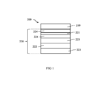
The sheet material 200 comprises at least one secondary layer 220. Figure 1
shows a
plurality of secondary layers 220. In the following, it is generally referred
to "secondary
layers 220", but the description is equally applicable to a single secondary
layer 220.
The secondary layers 220 comprise at least a moisture barrier layer 221 to
provide the
moisture barrier function. This is exemplarily shown in Figure 1. The moisture
barrier
layer 221 may be provided as a coating or a film. For example, the moisture
barrier layer
221 may comprise PVDC, nanocellulose, microcellulose, Silicon nitride, Silicon
oxide,
Aluminium, and/or Aluminium oxide. These may be applied as the moisture
barrier
layer 221 by laminating, spraying, lacquering, plasma coating, or by
metallisation. For
example, a physical vapour depositing process may be used. Preferably, the
moisture
barrier layer 221 may be applied directly on the primary sheet layer 210 (not
shown).
The secondary layers 220 may comprise additional layers described in the
following:
For example, the secondary layers 220 may comprise at least one base layer
224. This is
exemplarily shown in Figure 1. In the example of Figure 1, two base layers 224
are
provided for being applied directly onto the moisture barrier layer 221 and
the primary
sheet layer 210. Thus, the moisture barrier layer 221 may be sandwiched
between two
base layers 224. The base layer 224 may preferably provide a surface as a
base, on which
various other layers, e.g. films and/or coatings, may be adhered. For this,
for example,
the base layer 224 may be configured to provide a reduced pore size, air
permeability
CA 03228425 2024- 2-8
WO 2023/041331
PCT/EP2022/074276
16
and/or surface roughness in comparison to another layer of the sheet material
200, on
which the base layer 224 is applied. For example, the base layer 224 may have
a smaller
pore size or lower surface roughness than the primary sheet layer 210.
Alternatively or
additionally, the base layer 224 may form a surface with a surface roughness
comprised
in the range of from 30 to 800 Bendsten ml/min (Bendsten method). The base
layer 224
may be provided as a film or coating. For example, the base layer 224 may be a
(compostable) plastic material, like PBAT, PLA or regenerated cellulose.
Alternatively or additionally, it is also conceivable that the primary sheet
layer 210 may
ro comprise the (one) base layer 224 (or one of the base layers 224).
Therein, the base layer
224 may be provided by the cellulose-based material of the primary sheet layer
210. For
example, the primary sheet layer 210 may be mechanically or chemically treated
to
provide the functionality of the base layer 224. For this, a surface of the
primary sheet
layer 210 may be treated with acids, and/or may be exposed to pressure and
heat in a
calendering process.
The oxygen barrier function may be provided by the secondary layers 220, which
may
further comprise an oxygen barrier layer 222 to provide this function. In the
example
illustrated in Figure 1, the oxygen barrier layer 222 is shown as being
provided on an
opposite side to the primary sheet layer 210 with respect to the moisture
barrier layer
221. However, other arrangements of the oxygen barrier layer 222 are
conceivable. The
oxygen barrier layer 222 may be provided as a coating or a film. For example,
the oxygen
barrier layer 222 may be made of PVOH or BVOH. Therein, the oxygen barrier
layer 222
may be provided as one of the secondary layers 220 by laminating, spraying,
lacquering,
plasma coating or in a metallisation process.
Alternatively or additionally, the oxygen barrier function may be provided by
the
primary sheet layer 210. Therein, for example, the oxygen barrier function may
be
provided by the cellulose-based material of the primary sheet layer 210
itself. For
example, the primary sheet layer 210 may have a constitution or composition
that allows
to provide the above specified oxygen barrier functionality. For instance, the
primary
sheet layer 210 may comprise a high portion of fibres and/or may have a high
compactness. Alternatively or additionally, the primary sheet layer 210 may be
mechanically or chemically treated to establish the oxygen barrier function.
For this, a
surface of the primary sheet layer 210 may be treated with acids, and/or may
be exposed
to pressure and heat in a calendering process.
CA 03228425 2024- 2-8
WO 2023/041331
PCT/EP2022/074276
17
The secondary layers 220 may further comprise at least one masking layer 223
for
masking the oxygen barrier layer 222. In Figure 1, the oxygen barrier layer
222 is
exemplarily illustrated as being sandwiched between two masking layers 223.
Figure 1
illustrates further that the masking layer 223 may be applied directly onto
the base layer
224. The masking layer 223 may be provided as a film or coating. For example,
the
masking layer 223 may be a (compostable) plastic material, like PHA, PBAT or
PLA.
Preferably, the aforementioned strip 300 may comprise a moisture barrier
function and
an oxygen barrier function. For example, the strip 300 may have a layered
structure that
comprises a moisture barrier layer and an oxygen barrier layer. This is
exemplarily
illustrated in Figures 14 and 15. For example, the strip may comprise a
calendered paper
layer 302 (e.g. for providing an oxygen barrier) that may be sandwiched
between two
layers 301 made of compostable plastic (e.g. for providing a moisture
barrier). However,
it is also conceivable that the strip 300 is provided as a single-layer film
303 that merely
provides additional sealant material.
The capsule body no further comprises a bottom wall 120. This is shown, for
example,
in Figures 2 to 11. In particular, Figure lo shows an example for a design of
the bottom
wall 120. The bottom wall 120 may be made of the above described multilayered
sheet
material 200. Thus, Figure 1 may show a cross-section exemplary for the
sidewall iii
and/or the bottom wall 120. However, it is also conceivable that the bottom
wall 120 is
made of a different compostable material, like paper (for example, if the
sidewall 111 is
already made of the sheet material 200). The bottom wall 120 may have any
shape or
form. For example, the bottom wall 120 may have a circular, plate-like form.
The sidewall in and the bottom wall 120 together delimit a chamber 150 for
containing
a substance for the preparation of the beverage. Thus, the sidewall in and the
bottom
wall 120 may define the shape and contours of the chamber 150. Similarly, the
sidewall
in and the bottom wall 120 may determine the shape and contours of the capsule
loo.
This is exemplary shown in Figures 2 to 11.
The chamber 150 has an opening 151 that is opposite to the bottom wall 120
with respect
to the chamber 150. For example, the sidewall in may define (surround) an
opening 151
of the capsule body no and preferably the rim portion 114 may protrude
laterally away
from the opening 151. The chamber 150 may enclose a substance for beverage
preparation. For example, when injecting a fluid inside the capsule loo for
the beverage
preparation, the substance may interact with the fluid injected in the chamber
150 to
CA 03228425 2024- 2-8
WO 2023/041331
PCT/EP2022/074276
18
produce the desired beverage. Thus, in the beverage preparation process, the
chamber
150 (or more generally the capsule loo) may constitute a brewing chamber of
the
beverage preparation machine. Examples for substances may be roasted ground
coffee,
instant coffee, tealeaves, syrup concentrate, fruit extract concentrate,
chocolate,
dehydrated edible substances, and/or combinations thereof.
Preferably, the chamber 150 may be delimited by the primary sheet layer 210 or
the
secondary layers 220. For example, if the masking layer 223 is present, the
chamber 150
may be covered by the masking layer 223 and thus, form the surface coming into
contact
with the substance. Alternatively or additionally, the outside surface of the
capsule body
no may be delimited by the primary sheet layer 210 or the secondary layers 220
(and
the masking layer 223 in particular, if present). However, these are only
examples and
not a complete enumeration. In particular, any of the layers of the sheet
material 200
may form the most outer or most inner surface of the capsule 100.
Preferably, the bottom wall 120 may be a separate element from the sidewall
in. This is
exemplarily illustrated in Figures 2 to 10. The bottom wall 120 may be joined
to the
sidewall in by heat sealing or gluing. For this, the sidewall 111 may comprise
an
attachment portion 117 for attaching the bottom wall 120 to the sidewall 111.
For instance, in Figures 2 and 4, a portion of the bottom wall 120 is covered
on two
opposite sides by the sidewall in. For example, the attachment portion 117 may
be a
portion of the sidewall in that is folded over an end section 127 of the
bottom wall 120
such that the end section 127 of the bottom wall 120 is sandwiched between a
longitudinal end section 118 of the sidewall in and the attachment portion
117. The
longitudinal end section 118 of the sidewall in may be on an opposite end
(first end 101)
to the opening 151 with respect to the chamber 150. The end section 127 of the
bottom
wall 120 may be a portion of the bottom wall 120 projecting therefrom.
Naturally, it is
also conceivable that a portion of the sidewall iii may be covered on two
opposite sides
by the bottom wall 120. In Figures 6 to 10, an example for an alternative
arrangement is
shown. Therein, a portion of the sidewall in may be covered by a portion of
the bottom
wall 120 on one side. For example, the attachment portion 117 of the sidewall
111 may
overlap with the end section 127 of the bottom wall 120. In Figure 10, the
bottom wall
120 is exemplarily illustrated with a sloped surface 122 and a flat surface
121. When
joining the sidewall in and the bottom wall 120 of this example, overlap
exists between
the end section 127 of the sloped surface 122 and the longitudinal end section
118 of the
sidewall in. The sidewall in and the bottom wall 120 maybe heat sealed or
glued within
CA 03228425 2024- 2-8
WO 2023/041331
PCT/EP2022/074276
19
the area of overlap. Naturally, it is also conceivable that a portion of the
bottom wall 120
may be covered by the sidewall 111 on one side.
The bottom wall 120 may be arranged with respect to the sidewall in such that
the
bottom wall 120 is flush with the longitudinal end section 118 of the sidewall
111. This is
exemplarily shown in Figures 6 to 9. However, other configurations are
conceivable. For
example, the bottom wall 120 may be connected to the sidewall in such that the
longitudinal end section 118 (and the attachment portion 117) of the sidewall
111 projects
from the bottom wall 120 in a direction opposite to the opening 151. This is
exemplarily
shown in Figures 2 to 5.
A further aspect of the present invention relates to a method for producing
the capsule
100. The method comprises the step of providing a sheet made of the sheet
material 200.
Preferably, the primary sheet layer 210 may be provided (e.g. coated or
laminated) with
the individual layers of the secondary layers 220. The sheet material 200 is
formed into
the sidewall tn. Therein, the sheet material 200 may preferably be bent such
that the
secondary layers 220 form the outside of the capsule body no or face inside
the chamber
150. Further, additionally or alternatively, the bottom wall 120 is formed
from the sheet
material 200 (e.g. a separate section of said sheet or a separate sheet). The
bottom wall
120 is attached to the sidewall 111 so that the bottom wall 120 and the
sidewall in form
the capsule body no that encloses the chamber 150. The chamber is filled with
a
substance through the opening 151. The opening 151 is sealed with a membrane
400 to
close the chamber 150. The membrane 400 may be a compostable (plastic) film.
The
sealing step is exemplarily shown in Figure 11.
Figures 12 and 13 exemplarily illustrate advantages of the above method of
producing
the capsule too in view of the prior art. For example, in Figure 13, the
membrane 400 is
able to adapt accurately to the contours of the rim 114 of the capsule -too.
Tn comparison,
in Figure 12, a prior art beverage container 900 cannot be completely closed
by the
membrane 400. This is because beverage containers 900 may require that the
material
used for their bodies has a higher thickness to provide certain barrier
properties. At the
container rim 914, the higher material thickness causes that the membrane 400
cannot
completely cover the overlapping end sections 914A, 914B of a container
sidewall. Thus,
a gap or hollow space forms between the membrane 400 and the end sections
914A,
9148 that can be detrimental for the shelf life of the beverage container 900.
CA 03228425 2024- 2-8
WO 2023/041331
PCT/EP2022/074276
The invention is not limited by the embodiments as described hereinabove, as
long as
being covered by the appended claims. All the features of the embodiments
described
hereinabove can be combined in any possible way and be provided
interchangeably.
5 For example, it is also conceivable that the primary sheet
layer 210 may be provided on
either side with the secondary layers 220 described above and thus, may be
sandwiched
between the secondary layers 220.
CA 03228425 2024- 2-8