Language selection

Search

Patent 3228971 Summary

Third-party information liability

Some of the information on this Web page has been provided by external sources. The Government of Canada is not responsible for the accuracy, reliability or currency of the information supplied by external sources. Users wishing to rely upon this information should consult directly with the source of the information. Content provided by external sources is not subject to official languages, privacy and accessibility requirements.

Claims and Abstract availability

Any discrepancies in the text and image of the Claims and Abstract are due to differing posting times. Text of the Claims and Abstract are posted:

  • At the time the application is open to public inspection;
  • At the time of issue of the patent (grant).
(12) Patent Application: (11) CA 3228971
(54) English Title: METAL PRESSURE MEASURING CELL
(54) French Title: CELLULE DE MESURE DE PRESSION METALLIQUE
Status: Compliant
Bibliographic Data
(51) International Patent Classification (IPC):
  • G01L 9/00 (2006.01)
  • G01L 13/02 (2006.01)
  • G01L 19/14 (2006.01)
(72) Inventors :
  • HESS, JURG (Switzerland)
  • ZIMMERMANN, FREDERIC (Switzerland)
  • MULLER, JONAS (Switzerland)
  • KAPPELI, RAPHAEL (Switzerland)
(73) Owners :
  • HUBA CONTROL AG (Switzerland)
(71) Applicants :
  • HUBA CONTROL AG (Switzerland)
(74) Agent: SMART & BIGGAR LP
(74) Associate agent:
(45) Issued:
(86) PCT Filing Date: 2022-08-29
(87) Open to Public Inspection: 2023-03-09
Availability of licence: N/A
(25) Language of filing: English

Patent Cooperation Treaty (PCT): Yes
(86) PCT Filing Number: PCT/EP2022/073971
(87) International Publication Number: WO2023/031130
(85) National Entry: 2024-02-09

(30) Application Priority Data:
Application No. Country/Territory Date
CH070225/2021 Switzerland 2021-08-31

Abstracts

English Abstract

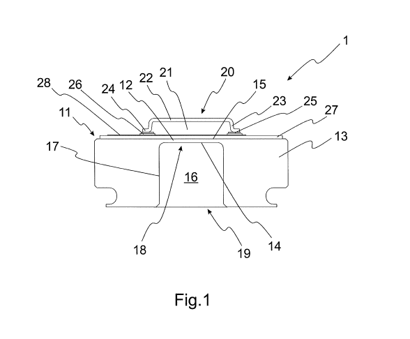
A metal pressure measuring cell (1) for absolute pressure sensing is described, comprising a metal base body (11) with a membrane (12) and a support body (13), the membrane comprising a first surface (14) and a second surface (15), the support body comprising a cavity (16) which is transversely delimited by an inner surface (17) of the support body and axially delimited at a first side (18) by the first surface of the membrane and open at a second side (19) opposite to the first side to form a trough- shaped chamber (16) for accommodating a measurement medium, the pressure measuring cell further comprising a cap (20) mounted on the base body and covering the second surface of the membrane such that a hermetically closed pressure reference volume (21) is formed between the cap and the second surface of the membrane, wherein the cap is made of metal.


French Abstract

L'invention concerne une cellule de mesure de pression métallique (1) pour la détection d'une pression absolue, comprenant un corps de base métallique (11) avec une membrane (12) et un corps de support (13), la membrane présentant une première surface (14) et une seconde surface (15), le corps de support comportant une cavité (16) qui est délimitée de manière transversale par une surface interne (17) du corps de support, délimitée de manière axiale sur un premier côté (18) par la première surface de membrane et ouverte sur un second côté (19) opposé au premier côté pour former une chambre en forme de goulotte (16) destinée à recevoir un milieu de mesure, la cellule de mesure de pression comportant en outre un capuchon (20) monté sur le corps de base et recouvrant la seconde surface de membrane de telle sorte qu'un volume de référence de pression hermétiquement fermé (21) est formé entre le capuchon et la seconde surface de membrane, le capuchon étant constitué de métal.

Claims

Note: Claims are shown in the official language in which they were submitted.


CA 03228971 2024-02-09
WO 2023/031130 PCT/EP2022/073971
- 41 -
Claims
1. A metal pressure measuring cell (1, 1', 1", 1.0, 2-8,
8', 9, 10, 11.0) for absolute pressure sensing,
comprising a metal base body (11, 11') with a membrane
(12, 12', 1.1", 1.1-7.1, 9.1, 10.1, 11.1) and a support
body (13, 13', 1.2", 1.2-7.2, 9.2, 10.2, 11.2), the
membrane comprising a first surface (14, 1.11", 1.11-
7.11, 9.11, 10.11, 11.11) and a second surface (15, 15',
1.12), the support body comprising a cavity (16, 1.21",
io 1.21-7.21, 9.21, 10.21, 11.21) which is transversely
delimited by an inner surface (17, 1.213", 1.213-7.213,
9.213, 10.213, 11.213) of the support body and axially
delimited at a first side (18, 1.211", 1.211-7.211) by
the first surface of the membrane and open at a second
side (19, 1.212", 1.212-7.212, 9.212, 10.212, 11.212)
opposite to the first side to form a trough-shaped
chamber (16, 1.21", 1.21-7.21, 9.21, 10.22, 11.22) for
accommodating a measurement medium, the pressure
measuring cell further comprising a cap (20, 20', 1.20",
1.20-7.20, 9.20, 10.20, 11.20) mounted on the base body
and covering the second surface of the membrane such
that a hermetically closed pressure reference volume
(21, 1.201", 1.201-7.201) is formed between the cap and
the second surface of the membrane, wherein the cap is
made of metal.
2. The pressure measuring cell (1, 1', 1", 1.0, 2-8, 8', 9,
10, 11.0) according to claim 1, wherein the cap (20,
20', 1.20", 1.20-7.20, 9.20, 10.20, 11.20) has an inner

CA 03228971 2024-02-09
WO 2023/031130 PCT/EP2022/073971
- 42 -
transverse area which is equal or larger than the area
of the membrane (12, 12', 1.1", 1.1-7.1, 9.1, 10.1,
11.1).
3. The pressure measuring cell (1, 1', 1", 1.0, 2-8, 8', 9,
10, 11.0) according to claim 1 or 2, wherein the
coefficients of expansion of the base body (11, 11') and
the cap (20, 20', 1.20", 1.20-7.20, 9.20, 10.20, 11.20)
are essentially equal.
4. The pressure measuring cell (1, 1', 1", 1.0, 2-8, 8', 9,
10, 11.0) according to one of the preceding claims,
wherein the base body (11, 11') and/or the cap (20, 20',
1.20", 1.20-7.20, 9.20, 10.20, 11.20) are made of a
duplex stainless, a ferritic or an austenitic steel.
5. The pressure measuring cell (1, l', 1", 1.0, 2-8, 8', 9,
10, 11.0) according to one of the preceding claims,
wherein the cap (20, 20', 1.20", 1.20-7.20, 9.20, 10.20,
11.20) has a circular cross-section.
6. The pressure measuring cell (1, 1', 1", 1.0, 2-8, 8', 9,
10, 11.0) according to one of the preceding claims,
wherein the cap (20, 20', 1.20", 1.20-7.20, 9.20, 10.20,
11.20) comprises a transverse cover portion (22, 22'), a
side wall (23) and a flange (24, 24') transversely
adjoining the side wall, wherein the cap is mounted on
the base body (11, 11') by the flange.
7. The pressure measuring cell (1, 1', 1", 1.0, 2-8, 8', 9,
10, 11.0) according to one of the preceding claims,
wherein the cap (20, 20', 1.20", 1.20-7.20, 9.20, 10.20,

CA 03228971 2024-02-09
WO 2023/031130 PCT/EP2022/073971
- 43 -
11.20) is mounted on the base body (11, 11') by
soldering, preferably soft soldering.
8. The pressure measuring cell (1, 1', 1", 1.0, 2-8, 8', 9,
10, 11.0) according to claim 7, comprising a solderable
metallic layer (25, 25') arranged between the base body
(11, 11') and the cap (20, 20') and surrounding the
second surface (15, 15') of the membrane (12, 12').
9. The pressure measuring cell according to claim 8,
wherein the solderable metallic layer is made of AgPd.
10. The pressure measuring cell (1, 1', 1", 1.0, 2-8, 8', 9,
10, 11.0) according to claim 8 or 9, comprising an
intermediate insulating layer (26, 26') arranged between
the base body (11') and the metallic layer (25, 25') and
surrounding the second surface (15, 15') of the membrane
(12, 12').
11. The pressure measuring cell according to one of the
preceding claims, wherein the pressure in the reference
volume is below 20 mbar, preferably below 10 mbar,
particularly preferably below 1 mbar.
12. The pressure measuring cell (1.0, 1", 2-8, 8', 9, 10,
11.0) according to one of the preceding claims, wherein
the inner surface (1.213", 1.213-7.213, 9.213, 10.213,
11.213) of the support body (1.2", 1.2-7.2, 9.2, 10.2,
11.2) is shaped such that a transverse diameter (D) of
the trough-shaped chamber (1.21", 1.21-7.21, 9.21,
10.22, 11.22) monotonously decreases from the second
side (1.212", 1.212-7.212, 9.212, 10.212, 11.212) of the

CA 03228971 2024-02-09
WO 2023/031130 PCT/EP2022/073971
- 44 -
cavity (1.21", 1.21-7.21. 9.21, 10.21, 11.21) towards
the first side (1.211", 1.211-7.211) of the cavity.
13. The pressure measuring cell (1.0, 1", 2, 3, 5-8, 8', 9,
10, 11.0) according to claim 12, wherein the inner
surface (1.213", 1.213-3.213, 5.213-7.213, 9.213,
10.213, 11.213) of the support body (1.2", 1.2-3.2, 5.2-
7.2, 9.2, 10.2, 11.2) adjoins the first surface (1.11",
1.11-3.11, 5.11-7.11, 9.11, 10.11, 11.11) of the
membrane (1.1", 1.1-3.1, 5.1-7.1, 9.1, 10.1, 11.1) with
a slope.
14. The pressure measuring cell (1.0, 1", 2, 7, 8, 8', 9,
10, 11.0) according to claim 12 or 13, wherein the inner
surface (1.213, 1.213", 2.213, 7.213, 9.213, 10.213,
11.213) of the support body comprises one or more
conical profile sections.
15. The pressure measuring cell (1", 8, 8', 9, 10, 11.0)
according to one of the claims 12 to 14, wherein the
inner surface (1.213", 9.213, 10.213, 11.213) of the
support body (1.2", 9.2, 10.2, 11.2) comprises a conical
profile extending from the second side (1.212", 9.212,
10.212, 11.212) of the cavity (1.21", 9.21, 10.21,
11.21) to the first side (1.211") of the cavity.
16. The pressure measuring cell (3, 4) according to one of
the claims 12 to 14, wherein the inner surface (3.213,
4.213) of the support body (3.2, 4.2) comprises one or
more concave, preferably concave parabolic, sections.
17. The pressure measuring cell (5-7) according to one of
the claims 12 to 14 or 16, wherein the inner surface

CA 03228971 2024-02-09
WO 2023/031130 PCT/EP2022/073971
- 45 -
(5.213-7.213) of the support body (5.2-7.2) comprises
one or more convex, preferably convex parabolic,
sections.
18. The pressure measuring cell (3, 5) according to claim 12
or 13, wherein the inner surface (3.213, 5.213) of the
support body (3.2, 5.2) comprises a parabolic profile
extending from the second side (3.212, 5.212) of the
cavity (3.21, 5.21) to the first side (3.211, 5.211) of
the cavity.
19. The pressure measuring cell (1, l', 1", 1.0, 2-8, 8', 9,
10, 11.0) according to one of the preceding claims,
wherein the trough-shaped chamber is an empty space
configured to solely accommodate the measurement medium.
20. The pressure measuring cell (1, l', 1", 1.0, 2-8, 8', 9,
10, 11.0) according to one of the preceding claims,
wherein the membrane (12, 12', 1.1", 1.1-7.1, 9.1, 10.1,
11.1) and the support body (13, 13', 1.2", 1.2-7.2, 9.2,
10.2, 11.2) are formed as an integral part such that the
trough-shaped chamber (16, 1.21", 1.21-7.21, 9.21,
10.22, 11.22) configured to accommodate the measurement
medium is formed by the integral part.
21. A method of manufacturing the pressure measuring cell
(1, 1', 1", 1.0, 2-8, 8', 9, 10, 11.0) according to one
of the preceding claims, comprising the steps of:
providing a base body (11, 11') made of a metal,
preferably a duplex stainless, a ferritic or an
austenitic steel, with a membrane (12, 12', 1.1", 1.1-

CA 03228971 2024-02-09
WO 2023/031130 PCT/EP2022/073971
- 46 -
7.1, 9.1, 10.1, 11.1) and a support body (13, 13', 1.2",
1.2-7.2, 9.2, 10.2, 11.2);
arranging an intermediate insulating layer (26, 26') on
the base body to surround the membrane;
forming a solderable metallic layer (25, 25') on the
intermediate insulating layer to surround the membrane;
mounting a cap (20, 20', 1.20", 1.20-7.20, 9.20, 10.20,
11.20) made of a metal on the base body by soldering a
mounting portion of the cap, preferably a flange (24,
24'), onto the solderable metallic layer.
22. The method according to claim 21, wherein the cap (20,
20', 1.20", 1.20-7.20, 9.20, 10.20, 11.20)
is
manufactured by punching and stamping of a sheet metal.
23. The method according to claim 21 or 22, wherein the
mounting portion (24, 24') of the cap (20, 20', 1.20",
1.20-7.20, 9.20, 10.20, 11.20) is soldered onto the
metallic layer by vacuum soldering.
24. The method according to one of the claims 21 to 23,
wherein the cap (20, 20', 1.20", 1.20-7.20, 9.20, 10.20,
11.20) is made of a duplex stainless steel, a ferritic
or an austenitic steel.
25. A pressure transducer (100, 100') configured to measure
pressure of a measurement medium with a density anomaly,
comprising a pressure measuring cell (8, 8') according
to one of the claims 1 to 20.

CA 03228971 2024-02-09
WO 2023/031130 PCT/EP2022/073971
- 47 -
26. The pressure transducer (100, 100') according to claim
25, wherein the trough-shaped chamber is an empty space
for accommodating solely the measurement medium.
27. A dosing unit (1000') for dosing an exhaust gas
reduction medium, preferably diesel exhaust fluid,
comprising a pressure transducer (100') according to
claim 25 or 26.

Description

Note: Descriptions are shown in the official language in which they were submitted.


CA 03228971 2024-02-09
W02023/031130 PCT/EP2022/073971
- 1 -
METAL PRESSURE MEASURING CELL
Field of the invention
The present invention relates to an absolute pressure
measuring cell made of metal, a pressure transducer
comprising a pressure measuring cell and a dosing unit for
dosing an exhaust gas reduction medium, comprising a pressure
transducer, and a method of manufacturing an absolute metal
pressure measuring cell.
Background of the invention
Pressure transducers are used to measure pressure of fluids
in various industrial applications. A common way to measure
the pressure of a fluid or measurement medium, respectively,
is to use a pressure measuring cell comprising a deflectable
membrane, where a surface of the membrane is facing a volume
of the measurement medium. Depending on the difference of the
pressures at the surface facing the volume containing the
measurement medium and at the surface facing away from the
volume with the measurement medium, the membrane experiences
a deflection which may be detected in order to determine the
pressure of the measurement medium.
Depending on the reference with respect to which the pressure
of the measurement medium is measured, different kinds of
pressure measuring cells are discerned. In an absolute
pressure measuring cell, for example, the pressure of the
measurement medium is determined with respect to vacuum or

CA 0213971 2024-02-09
WO 2023/031130 PCT/EP2022/073971
- 2 -
another fixed reference pressure. In a relative pressure
measuring cell, on the other hand, the pressure of the
measurement medium is determined with respect to the current
environment, such as for example atmospheric pressure.
A pressure transducer with a metal pressure measuring cell is
for example described in EP 3 128 305 Bl. There, a hermetic
pressure sensor for measuring a fluid pressure is described,
which comprises a first housing structure comprising a metal
membrane section to be exposed to the fluid pressure; a
second housing structure comprising a housing part with at
least two openings and electrical connection pins passing
through the at least two openings; at least one strain
sensing element and a PCB electrically coupled to the
electrical connection pins. The at least one strain sensing
element is attached to the membrane section and electrically
coupled to the PCB by bonding wires to mechanically decouple
the membrane section for force acting on the PCB, the housing
part of the second housing structure is a metal housing part
configured to form a cover over the first housing part, the
electrical connection pins are affixed in the at least two
openings by a non-conductive and hermetic sealing material,
springy electrical connection elements or a flex foil couple
electrically the connection pins to the PCB, the first
housing structure and the second housing structure are
hermetically connected to each other to form a hermetically
closed cavity in which the PCB and the at least one strain
sensing element are located, and the first housing structure
comprises a fluid facing outer surface to be exposed to the
fluid pressure wherein the fluid facing outer surface is a
full metal outer surface. The hermetic housing provides a

CA 03228971 2024-02-09
WO 2023/031130 PCT/EP2022/073971
- 3 -
constant internal pressure with respect to which the pressure
of the fluid can be measured.
Summary of the invention
For absolute pressure measuring cells made of metal, it is
desired to provide a fixed reference pressure in a simple and
reliable manner.
It is therefore an object of the invention to provide a metal
pressure measuring cell for absolute pressure sensing, a
pressure transducer comprising a metal pressure measuring
cell for absolute pressure sensing and a method of
manufacturing a metal pressure measuring cell for absolute
pressure sensing.
According to the present invention, the object is achieved by
the features of the independent claims. In addition, further
advantageous embodiments follow from the dependent claims and
the description as well as the figures.
According to an aspect of the invention, the object is
particularly achieved by a metal pressure measuring cell for
absolute pressure sensing, comprising a metal base body with
a membrane and a support body, the membrane comprising a
first surface and a second surface, the support body
comprising a cavity which is transversely delimited by an
inner surface of the support body and axially delimited at a
first side by the first surface of the membrane and open at a
second side opposite to the first side to form a trough-
shaped chamber for accommodating a measurement medium, the
pressure measuring cell further comprising a cap mounted on

CA 0213971 2024-02-09
WO 2023/031130 PCT/EP2022/073971
- 4 -
the base body and covering the second surface of the membrane
such that a hermetically closed pressure reference volume is
formed between the cap and the second surface of the
membrane, wherein the cap is made of metal.
By mounting a cap on the base body, covering the second
surface of the membrane, a hermetically closed volume for a
fixed reference pressure can be provided in a simple manner.
In particular, a complex arrangement of a housing surrounding
the whole pressure measuring cell can be avoided. Further, as
the cap is also made of metal, interfaces of different
materials, such as for example glass-metal or ceramics-metal
interfaces, which are prone to mechanical stress and failure,
can be avoided.
Preferably, the cap has an inner transverse area which is
equal or larger than the area of the membrane.
In this way, it can be ensured that the complete second
surface of the membrane is covered by the pressure reference
volume such that reliable absolute pressure sensing can be
enabled. Furthermore, it can be ensured that a joint by which
the cap is mounted on the base body is not arranged on top of
the membrane, such that the membrane can be protected from
mechanical load due to the joint. However, the joint is
preferably arranged next to the radial boundary of the
membrane such that the region of the joint can be kept simple
and small. This allows to reduce the probability of leakage
compared to e.g. large and complex joints which seal a
complete housing surrounding the entire pressure measuring
cell.

CA 03228971 2024-02-09
WO 2023/031130 PCT/EP2022/073971
- 5 -
Preferably, the coefficients of expansion of the base body
and the cap are essentially equal.
By choosing materials with essentially equal coefficients of
expansion for the base body and the cap, mechanical stress
due to temperature changes, can be reduced.
Preferably, the base body and/or the cap are made of a duplex
stainless, a ferritic or an austenitic steel.
Preferably, both the base body and the cap are made of a
duplex stainless, a ferritic or an austenitic steel. Besides
the equal coefficients of expansion, using a duplex
stainless, a ferritic or austenitic steel for both the cap
and the base body has the advantage that equal thermal
conductivities can be provided which increases thermal shock
resistance. Furthermore, a steel cap has the advantage that
the cap can hermetically be soldered on the base body with a
known surface-mount technology for SMDs (surface mounted
devices).
In some embodiments, the cap has a circular cross-section.
Alternatively, the cap may have a rectangular or other
polygonal cross-section.
In some embodiments, the cap comprises a transverse cover
portion, a side wall and a flange transversely adjoining the
side wall, wherein the cap is mounted on the base body by the
flange.
Such a shape of the cap has the advantage that it can readily
be manufactured by punching and stamping of a sheet metal.

CA 03228971 2024-02-09
WO 2023/031130 PCT/EP2022/073971
- 6 -
The flange provides a mounting portion which can be used for
soldering the cap on the base body in a reliable manner.
The height of the side wall can be adjusted to obtain a
pressure reference volume of a desired size. For example, the
volume of the pressure reference volume may be, in some
embodiments, larger than 40 mm3. In particular, the cap
allows to obtain a pressure reference volume of a
sufficiently large size while keeping the membrane and
therefore the lateral extent of the pressure measuring cell
sufficiently small. Further, with a defined size of the joint
with a certain expected leakage rate, the pressure increase
in the interior of the pressure reference volume is typically
smaller for larger size of the pressure reference volume.
Therefore, the cap advantageously allows to keep the pressure
in the interior of the pressure reference volume small.
In some embodiments, the cap is mounted on the base body by
soldering, preferably soft soldering.
The joints achieved by soldering have the advantage that an
improved thermal shock resistance can be provided.
Advantageously, a ductile soft solder joint is achieved which
has an improved thermal shock resistance with respect to e.g.
glass soldered joints. Furthermore, soldering the cap on the
base body has the advantage that the cycle time for joining
can be reduced to a few minutes. Soldering has the further
advantage that process temperatures can be reduced.
In some embodiments, the cap is mounted on the base body by
vacuum soldering. This has the advantage that pressures of a
few mbar, preferably smaller than 1 mbar, can be achieved
within the pressure reference volume.

CA 03228971 2024-02-09
WO 2023/031130 PCT/EP2022/073971
- 7 -
In some embodiments, a solderable metallic layer is arranged
between the base body and the cap, the solderable metallic
layer surrounding the second surface of the membrane.
The person skilled in the art understands that if the cap is
"mounted on the base body" or "soldered on the base body"
additional elements or layers such as for example the
solderable metallic layer and/or additional insulating layers
can be arranged between the cap and the base body which may
contribute to forming the joint between the cap and the base
body.
A soft solder may be deposited onto the metallic layer in a
vacuum soldering system.
The metallic layer may have an annular shape, in particular
for a cap with a circular cross-section.
In some embodiments, the solderable metallic layer is made of
AgPd.
Alternatively, the solderable metallic layer may be made of
Ag, AgPdPt or AgPt. Thick film materials such as AgPd, Ag,
AgPdPt or AgPt have the advantage of good solderability and
processability by lead-free low temperature reflow soldering.
Alternatively, the cap may be mounted on the base body using
a metallic layer made of for example Ti/Pd/Au,
Ta/TaiN/NiCr/Pd/Au, Ti/Pd/Cu/Ni/Au etc. if thin film
technology is used in manufacturing of the pressure measuring
cell.
In some embodiments, an intermediate insulating layer is
arranged between the base body and the metallic layer, the

CA 03228971 2024-02-09
WO 2023/031130 PCT/EP2022/073971
- 8 -
intermediate insulating layer surrounding the second surface
of the membrane. The intermediate insulating layer is an
electrically insulating layer.
The metallic layer and/or the intermediate insulating layer
are arranged to laterally surround the second surface of the
membrane such that the sensitivity of the membrane is not
negatively affected . Preferably, the metallic layer and/or
the intermediate insulating layer comprise an opening which
is flush with the second surface of the membrane.
In some embodiments, a base insulating layer is arranged on
the base body, covering also the second surface of the
membrane. The base insulating layer is an electrically
insulating layer. Pressure measuring components such as
circuit elements, conductive tracks, sensor resistors etc.
may then be applied onto the base insulating layer. The
intermediate insulating layer is preferably deposited onto
the base insulating layer carrying the pressure measuring
components.
Typically, the pressure measuring cell may therefore have the
following structure: base body, base insulating layer and
pressure measuring components, intermediate insulating layer,
solderable metallic layer, cap.
In some embodiments, the pressure in the pressure reference
volume is below 20 mbar, preferably below 10 mbar,
particularly preferably below 1 mbar.
In some embodiments, the inner surface of the support body is
shaped such that a transverse diameter of the trough-shaped

CA 03228971 2024-02-09
WO 2023/031130 PCT/EP2022/073971
- 9 -
chamber monotonously decreases from the second side of the
cavity towards the first side of the cavity.
Due to the monotonously decreasing transverse diameter of the
trough-shaped chamber between the second side of the cavity
and the first side of the cavity, a wall which is vertical
along substantially the entire axial length of the cavity can
be avoided. In particular, the different transverse diameters
allow to introduce to the inner surface of the support body
one or more slopes deviating from the vertical axis of the
pressure measuring cell. By introducing one or more slopes to
the inner surface of the support body, obstacles for the
measurement medium can be obtained such that the area across
which the freezing part of the measurement medium such as ice
can freely and directly propagate towards the first surface
of the membrane is reduced. This has the advantage that at
least part of the forces arising from freezing of the
measurement medium due to a density anomaly can be guided
away from the membrane. By guiding said forces away from the
membrane, mechanical stress on the membrane can be reduced
which improves the drift characteristics of a pressure
transducer comprising a pressure measuring cell according to
the present disclosure.
Therefore, an effective "geometric" frost protection for the
membrane can be obtained by shaping the trough-shaped chamber
serving as a measurement volume in a refined manner according
to the present disclosure. In particular, additional fault-
prone compensation components such as movable and/or
compressible/stretchable elements in the measurement volume
may advantageously be reduced or avoided.

CA 0213971 2024-02-09
WO 2023/031130 PCT/EP2022/073971
- 10 -
In the context of the present invention, "axial" shall
typically be understood as a direction perpendicular to the
membrane. Preferably, the axial direction of the pressure
measuring cell represents an axis of symmetry of the trough-
shaped chamber. The transverse direction or plane shall
therefore be understood as a direction or plane perpendicular
to the axial direction. The transverse diameters of the
trough-shaped chamber at different axial heights of the
pressure measuring cell shall be understood as the transverse
diameters of the pressure measuring cell in a common vertical
plane of the pressure measuring cell.
Due to the monotonously decreasing transverse diameter, a
trough-shaped chamber with a gradually widening cross-section
can be obtained. Further, a gradually widening inner profile
of the trough-shaped chamber may have the advantage that the
membrane area can be kept small.
In some embodiments, the inner surface of the support body
may be shaped such that the transverse diameter of the
trough-shaped chamber decreases strictly monotonously from
the second side of the cavity towards the first side of the
cavity. This allows to further increase the portions of the
inner surface of the support body provided to guide forces
arising from freezing away from the membrane.
In some embodiments, the inner surface of the support body
may comprise a section with a transverse diameter of the
trough-shaped chamber strictly monotonously decreasing
towards the first side of the cavity, wherein the section
extends over at least a quarter, a third or half of the axial
height of the trough-shaped chamber.

CA 03228971 2024-02-09
WO 2023/031130 PCT/EP2022/073971
- 11 -
In some embodiments, the ratio of the transverse diameter of
the membrane to the axial height of the trough-shaped chamber
is smaller than 3:1. In some embodiments, the ratio of the
transverse diameter of the membrane to the axial height of
the trough-shaped chamber is 1:1.
In some embodiments, the inner surface of the support body
adjoins the first surface of the membrane with a slope.
Providing the inner surface of the support body or the
cavity, respectively, with a slope adjacent to the membrane
and with respect thereto allows to optimize the frost
protection as the forces arising from freezing may be guided
away from the membrane in its close vicinity. The slope may
be formed by a linearly slanted section or by a curved
section of the inner surface of the support body.
In some embodiments, the inner surface of the support body
comprises one or more linearly slanted sections.
One or more linearly slanted sections may be introduced
depending on the desired amount or fraction of forces to be
guided away from the axial direction or the direction towards
the membrane, respectively. Especially, different linearly
slanted sections adjacent to another may exhibit different
slopes. The one or more linearly slanted sections may
furthermore be introduced with an optimized slope with
respect to the membrane in order to adjust the direction to
which the forces are guided when the measurement medium
freezes at the respective site. Additionally, the one or more
linearly slanted sections may be introduced taking into
account specific freezing parameters, such as the direction
of freezing of the measurement medium, which may depend on

CA 03228971 2024-02-09
WO 2023/031130 PCT/EP2022/073971
- 12 -
the structure and/or spatial mounting of the pressure
measuring cell. The one or more slanted sections may for
example take into account whether freezing of the measurement
medium tends to begin from a region at the second side of the
cavity or from a region at the first side of the cavity.
As increased widening of the trough-shaped chamber typically
yields a decreased wall strength of the support body, the
slope of the linearly slanted sections can be adjusted to
provide an optimal frost protection by guiding away of the
forces from the membrane and widening of the measurement
volume and at the same time to provide a sufficiently large
wall strength of the support body.
The linearly slanted sections may extend at least partially
over the inner surface of the support body along the
transverse peripheral direction. In some embodiments, the
linearly slanted sections may be or may be part of a surface
curved along the transverse peripheral direction of the
cavity. For example, a linearly slanted section may be part
of a cone. Alternatively or additionally, the linearly
slanted section may be or may be part of a planar surface.
The person skilled in the art therefore understands that the
linearly slanted sections may be represented by a linearly
slanted profile when taking a vertical cross-section through
the cavity or trough-shaped chamber, respectively.
The inner surface of the support body may be shaped to form a
trough-shaped chamber with n-fold rotational symmetry with
respect to the axial direction of the pressure measuring
cell.

CA 0213971 2024-02-09
WO 2023/031130 PCT/EP2022/073971
- 13 -
In some embodiments, the trough-shaped chamber may exhibit a
shape of a prismatoid extending over at least part of the
axial height of the cavity. In some embodiments, the trough-
shaped chamber may exhibit a shape of a frustum extending
over at least part of the axial height of the cavity.
In some embodiments, the inner surface of the support body
may be shaped to form a trough-shaped chamber with circular
symmetry with respect to the axial direction of the pressure
measuring cell. The trough-shaped chamber may for example
exhibit a shape of a cone extending over at least part of the
axial height of the cavity.
In some embodiments, the inner surface of the support body
comprises at least two linearly slanted sections, wherein a
linearly slanted section at the second side of the cavity
exhibits a smaller slope with respect to the membrane than a
linearly slanted section at the first side of the cavity.
Alternatively, the inner surface of the support body may
comprise at least two linearly slanted sections, wherein a
linearly slanted section at the second side of the cavity
exhibits a larger slope than a linearly slanted section at
the first side of the cavity.
The at least two linearly slanted sections may be formed by
planar surfaces and/or surfaces curved along the transverse
peripheral direction of the cavity.
In some embodiments, the inner surface of the support body
comprises one or more conical profile sections.
The one or more conical profile sections may be arranged
successively one after another. In particular, the one or

CA 03228971 2024-02-09
WO 2023/031130 PCT/EP2022/073971
- 14 -
more conical profile sections may extend over the
circumference of the trough-shaped chamber, such that a
rotationally symmetric profile may be obtained.
In some embodiments, a conical profile section, preferably
arranged adjacent to the membrane, corresponds at least
partially to a cone with an apex angle between 15 and 50 ,
preferably between 200 and 45 , particularly preferably
between 22 and 43 .
By increasing the apex angle, guiding the forces away from
the membrane when the measurement medium is freezing can be
improved. Further, widening of the trough-shaped chamber can
be increased. As increased widening of the trough-shaped
chamber typically yields a decreased wall strength of the
support body, the apex angle can be adjusted to provide an
optimal frost protection by guiding away of the forces from
the membrane and at the same time to provide a sufficiently
large wall strength of the support body.
In particular, the one or more conical profile sections may
correspond to a frustoconical shape due to the adjacent
membrane or other adjacent conical, cylindrical, convex or
concave profile sections.
In some embodiments, the inner surface of the support body
comprises a conical profile section adjacent to the membrane
and a cylindrical profile section adjoining the conical
profile section.
The conical profile section and the cylindrical profile
section may extend over the circumference of the trough-
shaped chamber. The cylindrical profile section may adjoin

CA 03228971 2024-02-09
WO 2023/031130 PCT/EP2022/073971
- 15 -
the conical profile section by forming a step, such that a
transverse annular surface area may be formed. The conical
profile section adjacent to the membrane may therefore
exhibit a smaller transverse cross-sectional area than the
cylindrical profile section at the point where the conical
profile section adjoins the cylindrical profile section. The
transverse annular surface area may take up part of the force
arising from freezing of the measurement medium and serve to
protect the membrane from stress due to freezing of the
measurement medium.
In some embodiments, the inner surface of the support body
comprises a further conical profile section arranged between
the cylindrical profile section and the second side of the
cavity.
In some embodiments, the inner surface of the support body
comprises a cylindrical profile section adjacent to the
membrane and a conical profile section adjoining the
cylindrical profile section. In particular, the conical
profile section may correspond to a frustoconical shape due
to the adjacent cylindrical profile section.
In some embodiments, the inner surface of the support body
comprises at least two conical profile sections, wherein a
cone corresponding to a conical profile section at the second
end of the cavity exhibits a smaller apex angle than a cone
corresponding to a conical profile section at the first end
of the cavity.
Alternatively, the inner surface of the support body may
comprise at least two conical profile sections, wherein a
cone corresponding to a conical profile section at the second

CA 03228971 2024-02-09
WO 2023/031130 PCT/EP2022/073971
- 16 -
end of the cavity exhibits a larger apex angle than a cone
corresponding to a conical profile section at the first end
of the cavity.
In some embodiments, the inner surface of the support body
comprises a conical profile extending from the second side of
the cavity to the first side of the cavity.
Providing a conical profile extending from the second side of
the cavity to the first side of the cavity has the advantage
of an efficient frost protection together with a simple
manufacturability of the pressure measuring cell.
In particular, the conical profile may correspond at least
partially to a cone with an apex angle between 15 and 50 ,
preferably between 20 and 45 , particularly preferably
between 22 and 43 .
In some embodiments, the inner surface of the support body
comprises one or more concave, preferably concave parabolic,
sections.
In the context of the present invention, a cylindrical
profile section shall not be understood as a concave profile
section. A concave profile section shall therefore usually be
understood as comprising a substantial concave curved portion
with respect to the (vertical) axis of the pressure measuring
cell. Preferably, the concave profile section may therefore
be a curved concave profile section with respect to the
(vertical) axis of the pressure measuring cell.
In some embodiments, the inner surface of the support body
comprises one or more convex, preferably convex parabolic,
sections.

CA 0213971 2024-02-09
WO 2023/031130 PCT/EP2022/073971
- 17 -
A convex profile section shall therefore usually be
understood as comprising a substantial convex curved portion
with respect to the (vertical) axis of the pressure measuring
cell. Preferably, the convex profile section may be a curved
convex profile section with respect to the (vertical) axis of
the pressure measuring cell. By providing one or more concave
and/or convex, preferably concave and/or convex parabolic,
profile sections, a smooth widening of the inner profile of
the trough-shaped chamber can be obtained. The concave and/or
convex profile sections may extend over the circumference of
the trough-shaped chamber. Depending on where the forces
arising from freezing of the measurement medium shall mainly
be guided away from the membrane, a concave or convex profile
section may be provided. For example, a concave profile
section may be provided at the first side of the cavity if
efficient guiding away of the forces from the membrane shall
be provided in this region of the cavity. A convex profile
section may for example be provided at the second side of the
cavity if efficient guiding away of the forces from the
membrane shall be provided in the region of the second side
of the cavity.
In some embodiments, the inner surface of the support body
comprises a parabolic profile extending from the second side
of the cavity to the first side of the cavity.
The parabolic profile may be concave or convex. In
particular, the parabolic profile may extend over the
circumference of the trough-shaped chamber. For a concave
parabolic profile, the parabolic profile may correspond to a
frustum paraboloid due to the membrane arranged at the first
side of the cavity.

CA 03228971 2024-02-09
WO 2023/031130 PCT/EP2022/073971
- 18 -
In some embodiments, the parabolic profile exhibits a larger
curvature at the second side of the cavity than at the first
side of the cavity.
Alternatively, the parabolic profile may exhibit a smaller
curvature at the second side of the cavity than at the first
side of the cavity.
The size of the curvatures of the parabolic profiles at the
second side and the first side of the cavity may be adjusted
with respect to each other depending on the desired geometry
of the trough-shaped chamber or pressure measuring cell,
respectively. For example, by choosing a convex parabolic
profile with a larger curvature at the second side than at
the first side of the cavity, a deeper trough-shaped chamber
can be obtained. By choosing a convex parabolic profile with
a smaller curvature at the second side than at the first side
of the cavity, a shallower trough-shaped chamber can be
obtained. Here, the vertical curvatures shall be considered
when the curvatures are compared.
In some embodiments, the inner surface of the support body
comprises at least two concave or convex profile sections,
wherein adjacent concave or convex profile sections adjoin to
one another forming a step-like profile.
In some embodiments, the inner surface of the support body
comprises at least a concave profile section and at least a
convex profile section adjoining to one another forming a
step-like profile.
Concave and/or convex profile sections may adjoin to one
another by forming a step, such that an annular surface area

CA 03228971 2024-02-09
WO 2023/031130 PCT/EP2022/073971
- 19 -
may be formed. The annular surface area may take up part of
the force arising from freezing of the measurement medium.
In some embodiments, the inner surface of the support body
comprises a concave or convex section adjacent to a conical
profile section.
In some embodiments, the inner surface of the support body
adjoins the first surface of the membrane perpendicularly.
In particular, the inner surface of the support body may
comprise a cylindrical profile section adjoining the first
surface of the membrane and a conical or concave or convex
profile section adjoining the cylindrical profile section by
forming a step.
In some embodiments where the inner surface of the support
body comprises a cylindrical profile section and a conical or
concave or convex profile section adjoining the cylindrical
profile section, the conical or concave or convex profile
section may extend over at least one third of the axial
height of the trough-shaped chamber and the cylindrical
profile section may extend over at most two thirds of the
axial height of the trough-shaped chamber. Other partitions
between the cylindrical profile section and the conical or
concave or convex profile section with respect to the axial
height of the trough-shaped chamber may also be possible, for
example half/half, at least two thirds/ at most one third, at
least one quarter/at most three quarters, at least three
quarters/at most one quarter etc.
In some embodiments where the inner surface of the support
body comprises a conical profile section and an adjoining

CA 03228971 2024-02-09
WO 2023/031130 PCT/EP2022/073971
- 20 -
concave or convex profile section, similar partitions between
the conical profile section and the concave or convex profile
section may be possible, for example half/half, at least two
thirds/ at most one third, at least one quarter/at most three
quarters, at least three quarters/at most one quarter etc.
In some embodiments where the inner surface of the support
body comprises a concave and a convex profile section or two
concave or convex profile sections, similar partitions
between the concave and convex profile sections or between
the two concave or convex profile sections may be possible,
for example half/half, at least two thirds/ at most one
third, at least one quarter/at most three quarters, at least
three quarters/at most one quarter etc.
In some embodiments where the inner surface of the support
body comprises two conical profile sections, similar
partitions between the two conical profile sections may be
possible, for example half/half, at least two thirds/ at most
one third, at least one quarter/at most three quarters, at
least three quarters/at most one quarter etc.
In some embodiments, the pressure measuring cell comprises a
coating on the inner surface of the support body. The coating
may comprise one or more of: a polymer, for example a
parylene, silicon, diamond-like carbon or hydrocarbon, TiAlN,
TiCN, TiSi.
The coating can advantageously be used to reduce the
roughness of the inner surface of the support body, such that
the friction between the trough-shaped chamber and the
measurement medium can be reduced.

CA 03228971 2024-02-09
WO 2023/031130 PCT/EP2022/073971
- 21 -
In some embodiments, the inner surface of the support body
exhibits a roughness Ra < 3.0 pm, preferably Ra < 2.0 pm,
particularly preferably Ra < 1.8 pm.
Reducing the roughness of the inner surface of the support
body may be achieved by a coating on the inner surface or by
a separate surface treatment of the inner surface of the
support body, such as for example lapping, polishing,
sandblasting, precision turning etc. Reducing the roughness
of the inner surface of the support body has the advantage
that freezing of the measurement medium can be delayed.
In some embodiments, the pressure measuring cell comprises a
liner insert for the trough-shaped chamber, wherein the liner
insert is arranged to cover at least part of the inner
surface of the support body transversely delimiting the
cavity.
Preferably, the liner insert covers the inner surface of the
support body transversely delimiting the cavity. Preferably,
the liner insert covers the side wall or side walls of the
trough-shaped chamber but leaves the membrane open. In some
embodiments, however, the liner insert may also cover the
first surface of the membrane. The liner insert can
advantageously be used to reduce the roughness of the inner
surface of the support body, such that the friction between
the trough-shaped chamber and the measurement medium can be
reduced. The liner insert may be made of a compressible
material. As the liner insert has a thickness which is larger
than the thickness of a coating, a certain flexibility and/or
compressibility can therefore be provided such that the liner

CA 03228971 2024-02-09
WO 2023/031130 PCT/EP2022/073971
- 22 -
insert may take up part of the forces arising from freezing
of the measurement medium.
The liner insert may comprise a shape which corresponds to
the profile of the inner surface of the support body. The
liner insert may therefore exhibit one or more conical
profile sections, a cylindrical profile section, one or more
concave and/or convex profile sections.
In some embodiments, the liner insert comprises outer ribs on
an outer surface facing the inner surface of the support body
for mounting the liner insert at the trough-shaped chamber.
Accordingly, the inner surface of the support body may
comprise recesses corresponding to the outer ribs of the
liner insert, wherein the outer ribs may be configured to
engage into the recesses, such that the liner insert may be
securely mounted at the trough-shaped chamber.
In some embodiments, the liner insert comprises outer ribs on
an outer surface facing the inner surface of the support body
for generating one or more buffer chambers between the inner
surface of the support body and the liner insert. In such
embodiments, the inner surface of the support may therefore
not comprise recesses in which the outer ribs engage into.
Instead, the outer ribs may abut on the even inner surface of
the support body and serve as spacer elements. The buffer
chambers may advantageously serve as compressible chambers to
take up a volume change of the freezing measurement medium.
In order to prevent the buffer chambers from compressing or
collapsing before the measurement medium freezes, the liner
insert is preferably made of a sufficiently rigid plastic.

CA 03228971 2024-02-09
WO 2023/031130 PCT/EP2022/073971
- 23 -
The liner insert may further comprise a flange configured to
abut on an outer transverse surface of the support body
adjacent to the second side of the cavity.
In some embodiments, the liner insert is made of a urea-
resistant elastomer, for example ethylene propylene diene
monomer rubber or nitrile butadiene rubber.
According to a further aspect, the present invention is also
directed to a method of manufacturing the pressure measuring
cell according to one of the preceding claims, comprising the
steps of: providing a base body made of a metal, preferably a
duplex stainless, a ferritic or an austenitic steel, with a
membrane and a support body; arranging an intermediate
insulating layer on the base body to surround the membrane;
forming a solderable metallic layer on the intermediate
insulating layer to surround the membrane; mounting a cap
made of a metal on the base body by soldering a mounting
portion of the cap, preferably a flange, onto the metallic
layer.
As described above, a base insulating layer may be formed on
the base body, covering the second surface of the membrane.
Pressure measuring components may be applied on the
insulating layer. Arranging the intermediate insulating layer
on the base body may therefore typically comprise applying
the intermediate insulating layer onto the base insulating
layer.
In some embodiments, the cap is manufactured by punching and
stamping of a sheet metal.

CA 03228971 2024-02-09
WO 2023/031130 PCT/EP2022/073971
- 24 -
In some embodiments, the mounting portion of the cap is
soldered onto the metallic layer by vacuum soldering.
In some embodiments, the cap is made of a duplex stainless
steel, a ferritic steel or an austenitic steel.
According to a further aspect, the present invention is also
directed to an absolute pressure transducer configured to
measure pressure of a measurement medium with a density
anomaly, comprising a pressure measuring cell according to
the present disclosure.
Due to the frost protection achieved by the particular
geometry of the trough-shaped chamber, the pressure measuring
cell may particularly be advantageous for use in a pressure
transducer configured to measure pressure of a measurement
medium with a density anomaly. In particular, additional
fault-prone compensation components such as movable and/or
compressible/stretchable elements in the measurement volume,
may advantageously be reduced or avoided for the pressure
transducer according to the present disclosure.
In some embodiments, the trough-shaped chamber is an empty
space for accommodating solely the measurement medium.
As mentioned above, additional compensation components such
as for example movable elements within the measurement volume
can be avoided such that the trough-shaped chamber can fully
be accommodated by the measurement medium.
In some embodiments of a pressure transducer with a conical
or parabolic profile extending from the second side to the
first side of the cavity, the pressure transducer may
optionally comprise a pin arranged at least partially in the

CA 03228971 2024-02-09
WO 2023/031130 PCT/EP2022/073971
- 25 -
trough-shaped chamber. The pin may have a cylindrical or a
conical shape. A pin of a conical shape has the advantage
that a portion of the freezing measurement medium may become
wedged with the pin and thereby be spatially fixed remote
from the membrane. The pin may be static or movable and
compressible or incompressible. A movable pin has the
advantage that the size of the measurement volume may be
adaptable during freezing of the measurement medium. A
compressible pin has the advantage that the pin may take up
part of the volume change when the measurement medium
freezes. A pin may further be used to advantageously control
the freezing characteristics e.g. by way of choosing a
material with a specific thermal conductivity in order to
adjust the regions where freezing of the measurement medium
begins earlier compared to configurations without a pin.
Although the "geometric" frost protection provided by the
profile of the trough-shaped chamber has the advantage that
additional compensation elements in the measurement volume
may be reduced or avoided, the optional pin may therefore
advantageously serve to additionally improve the frost
protection. Likewise, the pressure transducer may, in some
embodiments, comprise additional optional compensation
elements, such as for example a bellows on which the pressure
measuring cell is mounted by its second side of the cavity.
According to a further aspect, the present invention is also
directed to a dosing unit for dosing an exhaust gas reduction
medium, preferably diesel exhaust fluid, comprising a
pressure transducer according to the present disclosure.

CA 03228971 2024-02-09
WO 2023/031130 PCT/EP2022/073971
- 26 -
Brief description of the drawings
The present invention will be explained in more detail, by
way of exemplary embodiments, with reference to the schematic
drawings, in which:
Fig.1 .. shows an illustration of an embodiment of a
pressure measuring cell in a vertical cut view;
Fig.2 shows an illustration of an embodiment of a
pressure measuring cell in a perspective view
before mounting of the cap;
Fig.3 .. shows the pressure measuring cell of Fig.2 after
mounting of the cap;
Fig.4 shows illustration of an embodiment of a pressure
measuring cell in a vertical cut view with a cavity
comprising two conical profile sections;
Fig.5 .. shows an illustration of an embodiment of a
pressure measuring cell in a vertical cut view with
a cavity comprising a conical profile;
Fig.6 shows an illustration of an embodiment of a
pressure measuring cell in a vertical cut view with
a cavity comprising two conical profile sections
and a cylindrical profile section;
Fig.7 shows an illustration of an embodiment of a
pressure measuring cell in a vertical cut view with
a cavity comprising a concave parabolic profile;
Fig.8 shows an illustration of an embodiment of a
pressure measuring cell in a vertical cut view with

CA 03228971 2024-02-09
WO 2023/031130 PCT/EP2022/073971
- 27 -
a cavity comprising a cylindrical profile section
and a concave profile section;
Fig.9 shows an illustration of an embodiment of a
pressure measuring cell in a vertical cut view with
a cavity comprising a convex parabolic profile;
Fig.10 shows an illustration of an embodiment of a
pressure measuring cell in a vertical cut view with
a cavity comprising two convex profile sections;
Fig.11 shows an illustration of an embodiment of a
pressure measuring cell in a vertical cut view with
a cavity comprising a convex profile section and a
conical profile section;
Fig.12a shows an illustration of an embodiment of a
pressure transducer in a vertical cut view;
Fig.12b shows an illustration of a further embodiment of a
pressure transducer in a vertical cut view;
Fig.13 shows an illustration of an embodiment of a dosing
unit in a vertical cut view;
Fig.14 shows an illustration of an embodiment of a
pressure measuring cell in a vertical cut view
where a pin is arranged in the trough-shaped
chamber;
Fig.15 shows an illustration of an embodiment of a
pressure measuring cell in a vertical cut view with
a liner insert;

CA 0213971 2024-02-09
WO 2023/031130 PCT/EP2022/073971
- 28 -
Fig.16 shows an illustration of an embodiment of a
pressure measuring cell in a vertical cut view with
a liner insert.
Detailed description of exemplary embodiments
Figure 1 shows an illustration of an embodiment of a metal
pressure measuring cell 1 comprising a metal base body 11
with a membrane 12 and a support body 13. The membrane 12
comprises a first surface 14 and a second surface 15. The
support body 13 comprises a cavity 16 which is transversely
delimited by an inner surface 17 of the support body 13 and
axially delimited at a first side 18 by the first surface 14
of the membrane 12 and open at a second side 19 opposite to
the first side 18, such that a trough-shaped chamber 16 is
formed. The trough-shaped chamber 16 accommodates a
measurement medium, such as a diesel exhaust fluid. The first
surface 14 is facing towards the measurement medium and the
second surface 15 is facing away from the measurement medium.
The inner surface 17 of the support body 13 forms a side wall
surface of the cavity 16.
The pressure measuring cell 1 further comprises a cap 20
mounted on the base body 11 and covering the second surface
15 of the membrane 12. A hermetically closed pressure
reference volume 21 is formed between the cap 20 and the
second surface 15 of the membrane 12. The cap 20 comprises a
transverse cover portion 22, a side wall 23 and a flange 24
transversely adjoining the side wall 23. The cap 20 is
mounted on the base body 13 by the flange 24 by vacuum soft
soldering. A base insulating layer 27 is arranged on the base

CA 0213971 2024-02-09
WO 2023/031130 PCT/EP2022/073971
- 29 -
body 11, covering also the second surface 15 of the membrane
12. The base insulating layer 27 extends over a major portion
of the top surface of the base body 11. Pressure measuring
components 28, as symbolized by a solid line, are applied
onto the base insulating layer 27. An intermediate insulating
layer 26 is mounted on the base insulating layer 27 carrying
the pressure measuring components 28 so as to be arranged
between the base body 13 and a solderable metallic layer 25
made of AgPd. The solderable metallic layer 25 mounted on the
intermediate insulating layer 26 is arranged between the base
body 11 and the cap 20, wherein the cap 20 is soldered onto
the solderable metallic layer 25. The insulating layer 26 and
the metallic layer 25 have an annular shape with a central
opening which is flush with the second surface 15 of the
membrane 12. The cap 20 and the base body 11 are made of a
duplex stainless, ferritic or an austenitic steel. The
transverse area of the pressure reference volume 21 is larger
than the area of the second surface 15 of the membrane 12.
The pressure in the pressure reference volume 21 is smaller
than 1 mbar. The cap 20 and the transverse cover portion 22
have a circular shape. The cavity 16 has a cylindrical
profile. However, other profiles of the cavity 16 are
possible, as shown in the present disclosure. The cap 20 is
manufactured from a sheet metal by punching and stamping.
Figure 2 shows an illustration of an embodiment of a metal
pressure measuring cell 1' in a perspective view before
mounting of the cap. The metal base body 11' comprising the
membrane 12' and the support body 13' exhibits a circularly
symmetric shape (except for e.g. electrical structures such
as connection pins or small deviating structures of the base

CA 03228971 2024-02-09
WO 2023/031130 PCT/EP2022/073971
- 30 -
body such as recesses etc.). An intermediate insulating layer
26' is arranged on the base body 11'. In particular, the
intermediate insulating layer 26' is mounted on a base
insulating layer 27' carrying pressure measuring components.
The intermediate insulating layer 26' has an annular shape
surrounding the second surface 15' of the membrane 12'. On
the intermediate insulating layer 26', there is mounted a
solderable metallic layer 25', onto which the cap is to be
soldered. The metallic layer 25' has an annular shape
surrounding the second surface 15' of the membrane 12'. Four
connection pins 28' for electrically connecting to pressure
measuring components are arranged on the base body 11' of the
pressure measuring cell 1'.
Figure 3 shows the pressure measuring cell l' of Figure 2
after mounting of the cap 20'. The cap 20' is mounted on the
base body 11' by vacuum soft soldering of the flange 24' onto
the solderable metallic layer 25' shown in Fig.2. The
metallic layer 25' of Fig.2 is therefore arranged between the
base body 11' and the cap 20', in particular between the
intermediate insulating layer 26' and the flange 24'. The cap
20' has a circular transverse cross section and comprises a
circular transverse cover portion 22'.
Figure 4 shows an illustration of an embodiment of a metal
pressure measuring cell 1.0 comprising a membrane 1.1 with a
first surface 1.11 and a second surface 1.12. The pressure
measuring cell 1.0 is made of a duplex stainless, a ferritic
or an austenitic steel. The pressure measuring cell 1.0
further comprises a support body 1.2 with a cavity 1.21 which
is transversely delimited by an inner surface 1.213 of the
support body 1.2. The inner surface 1.213 of the support body

CA 03228971 2024-02-09
WO 2023/031130 PCT/EP2022/073971
- 31 -
1.2 therefore forms a side wall surface of the cavity 1.21.
The cavity 1.21 is axially delimited at a first side 1.211 by
the first surface 1.11 of the membrane 1.1 and open at a
second side 1.212 opposite to the first side 1.211. The
cavity 1.21 therefore forms a trough-shaped chamber 1.21
which accommodates a measurement medium, such as a diesel
exhaust fluid. The ratio of the transverse diameter of the
membrane 1.1 to the axial height of the trough-shaped chamber
1.21 is about 1:1. The first surface 1.11 of the membrane 1.1
is facing towards the measurement medium and the second
surface 1.12 of the membrane 1.1 is facing away from the
measurement medium.
As can be recognized in Figure 4, the transverse diameter D
of the trough-shaped chamber 1.21 at the second side 1.212 of
the cavity 1.21 is larger than the transverse diameter D of
the trough-shaped chamber 1.21 at the first side 1.211 of the
cavity 1.21. For the shown pressure measuring cell 1, the
transverse diameter D strictly monotonously decreases from
the second side 1.212 of the cavity 1.21 towards the first
side 1.211 of the cavity 1.21. The transverse diameter D at
different axial heights of the pressure measuring cell 1 is
measured in a common vertical plane oriented perpendicular to
the membrane 1.1. In the shown example, the common vertical
plane coincides with the plane of drawing.
The inner surface 1.213 of the support body 1.2 or the cavity
1.21, respectively, comprises a first conical profile section
adjacent to the membrane 1.1 and extending over about half of
the axial length of the trough-shaped chamber 1.21. The first
conical profile section corresponds to a cone (or a
frustocone) with an apex angle al. The inner surface 1.213 of

CA 0213971 2024-02-09
WO 2023/031130 PCT/EP2022/073971
- 32 -
the support body 1.2 or the cavity 1.21, respectively,
further comprises a second conical profile section adjoining
the first conical profile section and extending towards the
second side 1.212 of the cavity 1.21, corresponding to a cone
with a larger apex angle a2 than the cone of the first
conical profile section. The first and second conical profile
sections furthermore extend around the circumference of the
trough-shaped chamber 1.21 which exhibits circular symmetry
with respect to the axial direction of the pressure measuring
cell 1. The axial direction of the pressure measuring cell 1
is perpendicular to the plane of the membrane 1.1.
Due to the first conical profile section, the inner surface
1.213 of the support body 1.2 adjoins the first surface 1.12
of the membrane 1.1 with a slope. Furthermore, the first and
second conical profile sections represent linearly slanted
sections of the inner surface 1.213 of the support body 1.2
exhibiting two different slopes with respect to the plane of
the membrane 1.1, as the conical profile sections are only
curved in transverse direction and linearly slanted in
vertical direction. The person skilled in the art furthermore
understands that small curvatures as e.g. recognizable at the
transition from the first surface 1.11 of the membrane 1.1 to
the first conical profile section, due to for example
manufacturing imperfections are not to be understood as
concave or convex profile sections. The linearly slanted
section adjoining the first surface 1.11 of the membrane 1.1
is therefore to be understood disregarding such small
curvatures. Similarly, small chamfers e.g. at the first or
second side of the cavity without substantial effect on frost
protection shall not be understood as separate conical

CA 0213971 2024-02-09
WO 2023/031130 PCT/EP2022/073971
- 33 -
profile sections. The different apex angles mentioned above
translate into the slope of the linearly slanted section at
the second side 1.212 of the cavity 1.21 being smaller than
the slope of the linearly slanted section adjacent to the
membrane 1.1.
The pressure measuring cell 1.0 further comprises a cap 1.20
mounted onto the support body 1.2 and covering the second
surface 1.12 of the membrane 1.1. A hermetically closed
pressure reference volume 1.201 is formed between the cap
1.20 and the second surface 1.12 of the membrane 1.1. The cap
1.20 is made of a duplex stainless, a ferritic or an
austenitic steel.
Figure 5 shows a further embodiment of a metal pressure
measuring cell 1". The pressure measuring cell 1" is similar
to the pressure measuring cell 1 shown in Figure 4, with the
difference that the inner surface 1.213" comprises a conical
profile extending from the second side 1.212" of the cavity
1.21" to the first side 1.211" of the cavity 1.21" and that
the apex angle a" of the cone to which the conical profile
corresponds is larger than the apex angle a of the cone of
the first conical profile section shown in Figure 4. Due to
the larger apex angle, the trough-shaped chamber 1.21" of the
pressure measuring cell 1" exhibits a more efficient guiding
away of the forces from the membrane arising from freezing of
the measurement medium and a larger measuring volume compared
to the trough-shaped chamber 1.21 of the pressure measuring
cell 1 shown in Figure 4. The pressure measuring cell 1" also
comprises a cap 1.20" and a pressure reference volume 1.201".

CA 0213971 2024-02-09
WO 2023/031130 PCT/EP2022/073971
- 34 -
Figure 6 shows a further embodiment of a metal pressure
measuring cell 2 where the inner surface 2.213 of the cavity
2.21 or the support body 2.2, respectively, comprises a first
conical profile section adjacent to the first surface 2.11 of
the membrane 2.1 and a cylindrical profile section adjoining
the first conical profile section. The pressure measuring
cell 2 comprises a cap 2.20 and a pressure reference volume
2.201. The pressure measuring cell 2 is made of a duplex
stainless, a ferritic or an austenitic steel. The cylindrical
profile section and the first conical profile section adjoin
to each other forming a step 2.214 such that a transverse
annular surface area is formed. The inner surface 2.213 of
the support body 2.2 comprises a second conical profile
section arranged between the cylindrical profile section and
the second side 2.212 of the cavity 2.21. The first and
second conical profile sections correspond to a cone with the
same apex angle a, which has the advantage of easier
manufacturability. However, the apex angles may also differ
from one another depending on the desired freezing
characteristics.
Figure 7 shows a further embodiment of a metal pressure
measuring cell 3 with a cap 3.20 and a pressure reference
volume 3.201. The inner surface 3.213 of the support body 3.2
or the cavity 3.21, respectively, comprises a parabolic
profile extending from the second side 3.212 of the cavity
3.21 to the first side of the cavity 3.21. Due to the
parabolic profile, the inner surface 3.213 adjoins the first
surface 3.11 of the membrane 3.1 with a slope. The parabolic
profile represents a concave profile (section) of the inner
surface 3.213 of the support body 3.2 extending around the

CA 0213971 2024-02-09
WO 2023/031130 PCT/EP2022/073971
- 35 -
circumference of the trough-shaped chamber 3.21 (or the
cavity 3.21, respectively) and from the second side 3.212 to
the first side 3.211 of the cavity 3.21. The parabolic
profile exhibits a shape of a frustum paraboloid due to the
membrane 3.1 transversely intersecting the parabolic profile.
The curvature of the parabolic profile at the second side
3.212 of the cavity 3.21 is smaller than the curvature at the
first side 3.211 of the cavity 3.21. In comparing the
curvatures, the vertical curvatures shall be considered, as
shown in Figure 7. Guiding the forces arising from freezing
away from the membrane therefore occurs predominantly in the
vicinity of the membrane 3.1 in the region of the first side
3.211 of the cavity 3.21.
Figure 8 shows a further embodiment of a metal pressure
measuring cell 4 with a cap 4.20 and a pressure reference
volume 4.201. The inner surface 4.213 of the support body 4.2
comprises a cylindrical profile section adjoining the first
surface 4.11 of the membrane 4.1. The inner surface 4.213 of
the support body 4.2 therefore adjoins the first surface 4.11
of the membrane 4.1 perpendicularly. The cylindrical profile
section extends over the circumference of the trough-shaped
chamber 4.21. A concave profile section adjoins the
cylindrical profile section by forming a step 4.214. The
concave profile section extends over the circumference of the
trough-shaped chamber and from the cylindrical profile
section to the second side 4.212 of the cavity 4.21. The
concave profile section extends over about three quarters of
the axial height of the trough-shaped chamber 4.21 wherein
the cylindrical profile section extends over about one
quarter of the axial height of the trough-shaped chamber

CA 03228971 2024-02-09
WO 2023/031130 PCT/EP2022/073971
- 36 -
4.21. While a particular partition is shown in present Figure
8, it is clear that other partitions between the cylindrical
profile section and the concave profile section, as disclosed
above, are also possible.
Figure 9 shows a further embodiment of a metal pressure
measuring cell 5 with a cap 5.20 and a pressure reference
volume 5.201. The inner surface 5.213 of the support body 5.2
comprises a parabolic profile extending from the second side
5.212 to the first side 5.211 of the cavity 5.21 and over the
circumference of the trough-shaped chamber 5.21 (or the
cavity 5.21, respectively). Compared to the embodiment shown
in Figure 7, the parabolic profile is convex. The curvature
of the parabolic profile at the second side 5.212 of the
cavity 5.21 is larger than the curvature of the parabolic
profile at the first side 5.211 of the cavity 5.21. Guiding
the forces away from the membrane therefore occurs
predominantly in the region of the second side 5.212 of the
cavity 5.21. The inner surface 5.213 of the support body 5.2
adjoins the first surface 5.11 of the membrane 5.1 with a
large slope or almost perpendicularly.
Figure 10 shows a further embodiment of a metal pressure
measuring cell 6 with a cap 6.20 and a pressure reference
volume 6.201. The inner surface 6.213 of the support body 6.2
comprises two convex profile sections adjoining to one
another. A first convex profile section adjoins the membrane
6.1 with a slope and extends over the circumference of the
trough-shaped chamber 6.21. A second convex profile section
adjoins the first convex profile section by forming a step
6.214 and extends from the from the first convex profile
section to the second end 6.212 of the cavity 6.21. The

CA 0213971 2024-02-09
WO 2023/031130 PCT/EP2022/073971
- 37 -
second convex profile section also extends around the
circumference of the trough-shaped chamber 6.21. The second
convex profile section exhibits a smaller curvature than the
first convex profile section. The inner surface 6.213 of the
support body 6.2 is therefore steeper at the second convex
profile section than at the first convex profile section. The
second convex profile section in turn exhibits a larger
curvature at the second side 6.212 of the cavity than at the
step where the first and second convex profile sections
adjoin to one another. The first convex profile section
extends over about one third of the axial height of the
trough-shaped chamber 6.21 and the second convex profile
section extends over about two thirds of the axial height of
the trough-shaped chamber 6.21. While a particular partition
is shown in present Figure 10, it is clear that other
partitions between the two convex profile sections, as
disclosed above, are also possible.
Figure 11 shows a further embodiment of a metal pressure
measuring cell 7 with a cap 6.20 and a pressure reference
volume 6.201. The pressure measuring cell 7 is similar to the
pressure measuring cell 6 shown in Figure 10 with the
difference that instead of the second convex profile section,
a conical profile section adjoins the first convex profile
section. The inner surface 7.213 of the support body 7.2 thus
comprises a convex profile section adjoining the first
surface 7.11 of the membrane 7.1 and a conical profile
section adjoining the convex profile section by forming a
step. The conical profile section extends from the convex
profile section to the second side 7.212 of the cavity 7.21.
Both the convex profile section and the conical profile

CA 0213971 2024-02-09
WO 2023/031130 PCT/EP2022/073971
- 38 -
section extend over the circumference of the trough-shaped
chamber 7.21.
The pressure measuring cells as shown in Figures 4-16 may
comprise a base insulating layer, an intermediate insulating
layer and a solderable metal layer, as described for example
in connection with Figure 1, although not explicitly shown in
the Figures 4-16.
Figure 12a shows an embodiment of a pressure transducer 100
comprising an embodiment of a pressure measuring cell 8. The
pressure measuring cell 8 corresponds to the embodiment shown
in Figure 5 and comprises a trough-shaped chamber with a
conical profile.
Figure 12b shows an embodiment of a pressure transducer 100'
comprising an embodiment of a pressure measuring cell 8'.
Again, the pressure measuring cell 8' corresponds to the
embodiment shown in Figure 5 and comprises a trough-shaped
chamber with a conical profile. Different to the embodiment
of a pressure transducer shown in Figure 12a, the pressure
transducer 100' comprises a bellow 101' as a compensation
element to further improve the frost protection by enabling a
adaptable size of the measurement volume.
Figure 13 shows an embodiment of a dosing unit 1000' for
dosing an exhaust gas reduction medium comprising the
pressure transducer 100' of Figure 12b.
Figure 14 shows a further embodiment of a pressure measuring
cell 9 with a cap 9.20 where a pin 9.2 is at least partially
arranged in the trough-shaped chamber 9.21. The pin 9.3 has a
conical shape. A portion of ice of a measurement medium

CA 0213971 2024-02-09
WO 2023/031130 PCT/EP2022/073971
- 39 -
freezing from the second side 9.212 of the cavity 9.21 may
become wedged between the pin 9.3 and the inner surface 9.213
of the support body 9.2 and thereby be spatially fixed at a
site remote from the first surface 9.11 of the membrane 9.1.
Figure 15 shows a further embodiment of a pressure measuring
cell 10 with a cap 10.20. The inner surface 10.213 of the
support body 10.2 comprises a conical profile. A liner insert
10.215 is arranged in the cavity 10.21 to cover the inner
surface 10.213 of the support body 10.2 forming the side wall
of the cavity 10.21. The liner insert 10.215 comprises ribs
10.216 which engage with corresponding recesses in the inner
surface 10.213 of the support body 10.2 for secure mounting
of the liner insert 10.215. The liner insert 10.215 further
comprises a flange 10.217 which abuts on an outer transverse
surface of the support body 10.2 at the second side 10.212 of
the cavity 10.21. The liner insert 10.215 has a conical shape
and forms a side wall of the trough-shaped chamber 10.22. The
liner insert 10.215 is open at the upper end in order to
leave the first surface 10.11 of the membrane 10.1 open. The
liner insert 10.215 is made of a urea-resistant elastomer and
has a lower roughness than the inner surface 10.213 of the
support body 10.2.
Figure 16 shows a further embodiment of a pressure measuring
cell 11.0 with a liner insert 11.215 and a cap 11.20. The
inner surface 11.213 of the support body 11.2 comprises a
conical profile, similar to the embodiment shown in Figure
15. A liner insert 11.215 is arranged in the cavity 11.21 to
cover the inner surface 11.213 of the support body 11.2
forming the side wall of the cavity 11.21. The liner insert
11.215 comprises outer ribs 11.216 which abut on the even

CA 0213971 2024-02-09
WO 2023/031130 PCT/EP2022/073971
- 40 -
inner surface 11.215 of the support body 11.2 such that
buffer chambers 11.218 filled with air are arranged between
the liner insert 11.215 and the inner surface 11.213 of the
support body 11.2. The outer ribs 11.216 therefore serve as
spacer elements for generating the buffer chambers 11.218. In
case of freezing of the measurement medium, the buffer
chambers 11.218 may be compressed such that the increase in
measurement volume can be compensated for. The liner insert
11.215 further comprises a flange 11.217 which abuts on an
outer transverse surface of the support body 11.2 at the
second side 11.212 of the cavity 11.21. The liner insert
11.215 has a conical shape and forms a side wall of the
trough-shaped chamber 11.22. Further, the liner insert 11.215
also covers the first surface 11.11 of the membrane 11.1 in
order to prevent the measurement medium, such as a urea-water
solution to creep into the buffer chambers 11.218. The liner
insert 11.215 is made of a urea-resistant plastics with a
sufficient rigidity to withstand the fluid pressure of the
measurement medium before freezing. Therefore, the liner
insert 11.215 preferably exhibits a larger rigidity than the
liner insert 10.215 shown in Figure 15. Furthermore, the
liner insert 11.215 preferably has a lower roughness than the
inner surface 11.213 of the support body 11.2.

Representative Drawing
A single figure which represents the drawing illustrating the invention.
Administrative Status

For a clearer understanding of the status of the application/patent presented on this page, the site Disclaimer , as well as the definitions for Patent , Administrative Status , Maintenance Fee  and Payment History  should be consulted.

Administrative Status

Title Date
Forecasted Issue Date Unavailable
(86) PCT Filing Date 2022-08-29
(87) PCT Publication Date 2023-03-09
(85) National Entry 2024-02-09

Abandonment History

There is no abandonment history.

Maintenance Fee


 Upcoming maintenance fee amounts

Description Date Amount
Next Payment if standard fee 2024-08-29 $125.00
Next Payment if small entity fee 2024-08-29 $50.00

Note : If the full payment has not been received on or before the date indicated, a further fee may be required which may be one of the following

  • the reinstatement fee;
  • the late payment fee; or
  • additional fee to reverse deemed expiry.

Patent fees are adjusted on the 1st of January every year. The amounts above are the current amounts if received by December 31 of the current year.
Please refer to the CIPO Patent Fees web page to see all current fee amounts.

Payment History

Fee Type Anniversary Year Due Date Amount Paid Paid Date
Application Fee 2024-02-09 $555.00 2024-02-09
Owners on Record

Note: Records showing the ownership history in alphabetical order.

Current Owners on Record
HUBA CONTROL AG
Past Owners on Record
None
Past Owners that do not appear in the "Owners on Record" listing will appear in other documentation within the application.
Documents

To view selected files, please enter reCAPTCHA code :


To view images, click a link in the Document Description column. To download the documents, select one or more checkboxes in the first column and then click the "Download Selected in PDF format (Zip Archive)" or the "Download Selected as Single PDF" button.

List of published and non-published patent-specific documents on the CPD .

If you have any difficulty accessing content, you can call the Client Service Centre at 1-866-997-1936 or send them an e-mail at CIPO Client Service Centre.


Document
Description 
Date
(yyyy-mm-dd) 
Number of pages   Size of Image (KB) 
Abstract 2024-02-09 2 67
Claims 2024-02-09 7 225
Drawings 2024-02-09 17 278
Description 2024-02-09 40 1,782
Representative Drawing 2024-02-09 1 10
Patent Cooperation Treaty (PCT) 2024-02-09 2 99
International Search Report 2024-02-09 3 91
National Entry Request 2024-02-09 6 198
Cover Page 2024-02-26 1 42