Note: Descriptions are shown in the official language in which they were submitted.
CA 03229393 2024-02-14
WO 2023/027924
PCT/US2022/040576
VENTED LINER
CROSS-REFERENCE TO RELATED APPLICATIONS
[0001] This application claims benefit of United States Provisional
Application Number
63/237,401, filed August 26, 2021., which is hereby incorporated herein by
reference in its
entirety.
FIELD
[0002] The disclosure relates to sealing members for sealing to the rim of
a container,
and more particularly, to vented sealing members.
BACKGROUND
[0003] It is often desirable to seal the opening of a container using a
seal, sealing
member, or inner seal. Often a cap or other closure is screwed or placed over
the container
opening capturing the sealing member therein. In use, a consumer typically
removes the
cap or other closure to gain access to the sealing member and then removes or
otherwise
peels the seal from the container in order to dispense or gain access to its
contents. In some
forms, the user may puncture the seal to gain access to the interior contents
of the container.
[0004] Initial attempts at sealing a container opening utilized an
induction- or
conduction-type inner seal covering the container's opening where the seal
generally
conformed to the shape of the opening such that a circular container opening
was sealed
with a round disk approximately the same size as the opening. These prior
seals commonly
had a lower heat activated sealing layer to secure a periphery of the seal to
a rim or other
upper surface surrounding the container's opening. Upon exposing the seal to
heat, the
lower layer bonded to the container's rim. In many cases, these seals included
a foil layer
capable of forming induction heat to activate the lower heat seal layer.
[0005] However, problems still arise with sealing members when the contents
of the
container require pressure equalization. Sealed gas-tight containers require
venting when
gas pressure must be equalized between the interior and exterior of the
container. Without
venting, a flexible gas-tight container will bloat, leak, and possibly burst
when the interior
pressure exceeds the exterior pressure. Bloating can occur when the contents
of the container
generates gasses or heat by chemical reaction, for example when the contents
include a
peroxide-based toothpaste. Bloating can also occur when the container is
stored in a heated
environment. Similarly, an. unvented flexible gas-tight container will
collapse when the
- 1 -
CA 03229393 2024-02-14
WO 2023/027924
PCT/US2022/040576
internal pressure is reduced, for example when atmospheric oxygen is
scavenged, by one of
the ingredients housed in the container. Some modes of transportation put a
container at
risk of both bursting and collapse. During transport through mountains and
valleys, for
example, a container is subjected to pressures that can rise above and drop
below sea level
pressure. Rigid gas-tight containers, such as glass containers, are
susceptible to bursting or
imploding if the internal and external pressures become sufficiently
discrepant.
[0006] One way to equalize pressure is to provide a filter vent in the cap,
lid, or other
closure of a container. Filter vents generally include a gas-permeable filter,
or other gas
permeable microporous medium, which is interposed between the interior of the
container
and a vent aperture. The filter vent permits gases to diffuse in and out of
the interior of the
container, via, the vent aperture, while excluding particulates larger than a
threshold size, as
well as liquids of a particular range of hydrophobicity.
[00071 However, filter caps have other drawbacks. The pores of the filter
are susceptible
to being filled and clogged by the contents of the container. Further, the
filter can make it
difficult to puncture the seal. This may be a result of the added layers of
the filter material,
the filter material itself, and/or the adhesives used to seam the filter to
the sealing member.
This can be especially problematic when a user desires to precisely dispense
the contents of
the container if the sealing member is pierced and jagged remnants of the
sealing member
and filter remain on the container.
[00081 Further, depending on the properties of the contents of the
container, the
contents themselves can easily block, clog, or otherwise render the vent
deficient. For
example, materials with high viscosity, high tackiness, and other similar
properties are more
prone to dogging vents. Such materials can come into contact with the vent,
such as during
manufacture, transport, and the like, such that once they come into contact,
they are not
easily removed from the vent.
SUMMARY
[0009] In one form, the present application proceeds contrary to
conventional wisdom.
Prior venting caps and seals would traditionally increase the size of the vent
to minimize the
impact of the contents on the vent function. It was previously thought that by
increasing the
surface area of the vent, the likelihood of the vent being entirely blocked
would decrease.
Similarly, prior systems incorporated the vent material or layer on an
underside of the seal
and oftentimes also included a cover over a portion of the vent. In this
regard, it was
- 2 -
CA 03229393 2024-02-14
WO 2023/027924
PCT/US2022/040576
previously thought that the cover helped prevent the contents of the container
from
contacting the vent.
NOM The present concept, on the other hand, proceeds contrary to this
conventional
wisdom and can achieve improved performance compared to prior venting systems.
In one
form, the vent material is positioned on an opposite side of the sealing
member and/or
support member from the contents of the container. Further, the sealing member
and/or
support member can be used to define a vent opening to prevent contact between
the
contents and the vent material. The vent opening can be configured to be
small, especially
compared to many prior vent openings. By doing this, pressure can be
concentrated on a
much smaller surface area to dear any dogs from the vent opening and/or vent
material.
[0011] In some forms, a vented sealing member for sealing to a rim of a
container is
provided. The vented sealing member includes a support member, a sealant
layer, and a
vent layer. The support member can include at least one layer with the support
member
defining a vent opening extending from a lower surface to an upper surface
through the
support member. The sealant layer can be positioned on the lower surface of
the support
member for securing the vented sealing member to the rim of the container. The
vent layer
can be positioned over the vent opening and coupled to the upper surface of
the support
member.
[0012] According to some forms, a laminate for forming a vented sealing
member for
sealing to a rim of a container is provided. The laminate ind:u.des a support
member, a
sealant layer, and a vent layer. The support member can include at least one
layer with the
support member defining a vent opening extending from a lower surface to an
upper
surface through the support member. The sealant layer can be positioned on the
lower
surface of the support member for securing the vented sealing member to the
rim of the
container. The vent layer can be positioned over the vent opening and coupled
to the upper
surface of the support member.
[0013] In accordance with some forms, a method of forming a vented sealing
member
for sealing to a rim of a container is provided. The method includes the steps
of providing a
support member having at least one layer, the support member having a lower
surface and
an upper surface, forming a vent opening extending from the lower surface to
the upper
surface through the support member, and positioning a vent layer over the vent
opening
and coupling the vent layer to the upper surface of the support member.
- J -
CA 03229393 2024-02-14
WO 2023/027924
PCT/US2022/040576
[0014] In some forms, the vent layer is welded to the upper surface of the
support
member.
[0015] According to some forms, the vent opening has a diameter of about
0.005 to
0.060 inches.
[0016] In some forms, the vent opening has an exposed surface area of about
0.00070 to
about 0.0282 square inches.
[0017] In accordance with some forms, the vent opening has an exposed
surface area
that is about 80% or less of the vent material effective filter area.
[OWES] According to some forms, the vent opening has an exposed surface
area that is
about 30% or less of the vent material effective filter area.
[0019] In accordance with some forms, the support member is a laminate
comprising a
plurality of layers.
[0020] According to some forms, the support member comprises at least one
of a
polymer film, a polymer foam, a metal foil, a pulp material, paper, and
combinations
thereof.
[0021] In some forms, the sealing member further includes an upper laminate
partially
coupled to the support member and defining a tab.
[0022] In accordance with som.e forms, the vent layer comprises expanded
polyteixaflu.oroethylene.
[0023] In some forms, the sealing member includes a foil liner where an
ePTFE vent
material is welded to the back side of the liner, opposite the induction foil
layer. Such a vent
material could be welded onto a foam side of the sealing member.
[0024] According to some forms, the combination of a small vent hole and
ePTFE vent
material facing away from the contents of the container allows for thick
viscous products to
be cleared from the vent hole and ePTFE vent material when pressure returns
into the sealed
package. The vent layer prevents product from escaping and allows for sterile
air to return
into the container.
[0025] In some forms, the sealing members may be used with products that
are thick
and viscous. Typically, such products will coat the vent material and prevent
pressure
equalization. Many of these products are normally hot filled and when the
product cools
- 4 -
CA 03229393 2024-02-14
WO 2023/027924
PCT/US2022/0405 76
within the sealed container the pressure within the container will drop
causing the container
to panel. Using the sealing members described herein may allow the containers
to vent
products that normally do not have a suitable vented solution. Exemplary
materials ind:u.de,
but are not limited to, motor oil, hair conditioner, shampoo, car wax, laundry
detergents,
liquid soap, nail polish cleaner, industrial cleaning products, pet foods,
floor cleaner/wax,
hand/body lotions, and the like.
[0026] These and other aspects may be understood more readily from the
following
description and the appended drawings.
BRIEF DESCRIPTION OF THE DRAWINGS
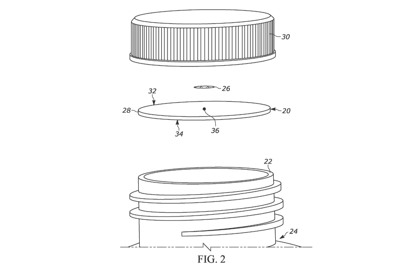
[0027] FIG. I is a perspective view of one form of a vented sealing member;
[00281 FIG. 2 is a is an exploded view of a vented, sealing member,
container, and cap;
[0029] FIG. 3 is a perspective view of a vented sealing member with the
vent material
removed to illustrate the vent opening;
[0030] FIG. 4 is a cross-sectional view of a support member with a vent
material
applied thereto;
[0031] FIG. 5 is a cross-sectional view of another vented sealing member;
[00321 FIG. 6 is a cross-sectional view of another vented sealing member;
and
[00331 FIG. 7 is a perspective view of a vented sealing member with a tab.
DETAILED DESCRIPTION
NOM For the purpose of facilitating an understanding of the subject
matter sought to
be protected, there are illustrated in the accompanying drawings embodiments
thereof, from
an inspection of which, when considered in connection with the following
description, the
subject matter sought to be protected, its construction and operation, and
many of its
advantages should be readily understood and appreciated.
[0035] A vented sealing member for sealing to a container is provided
herein. In
further forms, a tabbed and vented sealing member for a container is described
herein
containing an upper portion having a pull tab bonded to a lower portion
capable of being
sealed to a container's mouth or opening. In other forms, the various sealing
members may
be sealed via a pressure sensitive sealant layer. It should also be
appreciated that the sealing
- 5 -
CA 03229393 2024-02-14
WO 2023/027924
PCT/US2022/040576
member may have an external tab, extending outward beyond the lid of the
container
and/or may be a tab-free sealing member.
[0036] For simplicity, this disclosure generally may refer to a container
or bottle, but the
sealing members herein may be applied to any type of container, bottle,
package or other
apparatus having a rim or mouth surrounding an access opening to an internal
cavity. In
this disclosure, reference to upper and lower surfaces and layers of the
components of the
sealing member refers to an orientation of the components as generally
depicted in figures
and when the sealing member is in use with a container in an upright position
and having
an opening at the top of the container. Different approaches to the sealing
member will first
be generally described, and then more specifics of the various constructions
and materials
will be explained thereafter.
[0037] It should be appreciated that the vented sealing members described
herein may
be used in a variety of different types of sealing members. For example, the
vented sealing
members may take the form of an induction sealing member, a conduction sealing
member,
a pressure sensitive adhesive sealing member, as well as other types of
sealing members.
The vented sealing members may also be in the form of a foam liner or sealing
member, a
flexible film, and the like. i.e vented sealing members may also include one
or more tabs
for removal of the sealing member.
[0038] It should also be appreciated that the vented sealing members
described herein
may be used in a variety of configurations with a variety of different
combinations of layers.
For example, the sealing members may indude polymer foams, films,
coextrusions, foils,
membranes, adhesives, paper, cardboard, as well as other materials that are
used in sealing
members. The thicknesses and positions of each of the layers may be modified
as desired for
a partiailar application.
[0039] As shown in FIG. 1, a vented sealing member 20 is shown installed on
a rim 22
of a container 24. The vented sealing member 20 includes a vent material 26
installed on a
support member 28. FIG. 2 illustrates an exploded view of the sealing member
20 with the
container and a cap 30. As shown in this figure, the vent material 26 is
positioned at an
upper surface 32 of the support member 28, opposite a lower surface 34.
[0040] Turning to FIG. 3, it can be seen that the support member 28 defines
a vent
opening 36. The vent opening extends from the lower surface 34 to the upper
surface 32 of
the support member 28. The vent opening generally permits fluids, such as
gases to pass
- 6 -
CA 03229393 2024-02-14
WO 2023/027924
PCT/US2022/040576
between the vent material 26 and an interior of the container 24 when the
sealing member 20
is installed.
[0041] As shown in FIG. 4, the vent material 26 is installed such that it
surrounds the
vent opening 36 at the upper surface 32. In this form, the vent material 26
would have
decreased contact with the contents of the container. Further, the vent
material 26 is
installed, such as by welding, so that there are no gaps in the contact
between the vent
material 26 and the upper surface 32 to prevent gas from escaping anywhere
except through
the vent material 26. It should be appreciated that the surface area of the
vent material 26
may be varied along with the surface exposure or diameter of the vent opening
36. The vent
material 26 may also be secured at a peripheral edge thereof or at a location
closer to the
vent opening 36.
[0042] The sealing member 20 may also include a sealant layer 40 on the
lower surface
34 of the support member 28. The sealant layer 40 may take the form of a layer
that covers
the entire surface area of the lower surface 34. In this form, the vent
opening 36 would also
extend through the sealant layer 40.1n some forms, the sealant layer 40 may
cover just a
portion of the surface area of the lower surface 34 such as just at the
periphery thereof. In
this form, it would be unnecessary for the vent opening 36 to extend through
the sealant
layer 40.
[0043] Further discussion regarding some of the above-described components
and
details thereof will be provided below. The support member 28 may be a single
layer,
multiple layers, combinations of different materials, and combinations
thereof. In one form,
the support member 28 may be a single layer comprising a single material and
in other
forms it may be a single layer comprising a combination of materials.
[0044] In some forms, the support member 28 may include a plurality of
layers with
varying components in each layer. For example, referring to FIG. 5, the
support member 28
includes the sealant layer 40, a membrane layer 42, a support layer 44, and an
insulating
layer 46. It should be appreciated that the position, number, combination, and
configuration
of these layer may be modified as needed for a particular application.
[0045] The membrane layer 42 may be provided for barrier properties, such
as oxygen
and moisture barrier. The membrane layer 42 may also provide induction
heating, such as in
the form of a metal foil or other inductive material. The support layer 44 may
also provide a
variety of functions such as supporting other layers, insulation, adhesion
between layers,
- 7 -
CA 03229393 2024-02-14
WO 2023/027924
PCT/US2022/040576
and the like. The insulating layer 46 may also provide various functions such
as insulation,
compressibility (such as during cap installation), as well as providing a
suitable surface to
adhere to other components, such as the vent material.
[0046] One form of a vented sealing member 50 is shown in FIG. 6. In this
form, the
sealing member 50 includes a support member 52 having a plurality of layers.
The sealing
member 50 includes a sealant layer 54, an induction heating layer 56, a
polymer film 58, a
polymer foam 60, and a vent material layer 62.
[0047] Yet another form. of sealing member 70 is shown in FIG. 7. This view
shows the
vent material 26 exploded from the sealing member 70 to better illustrate the
placement of
the vent opening 36. Sealing member 70 is generally considered a tabbed
sealing member as
it includes a tabbed portion 72 to enable a user to grasp the tabbed portion
72 and remove
the sealing member 70 from a container.
[00481 Sealing member 70 indudes many of the same features as discussed
above, but
includes an upper portion 74 that is partially adhered to a support member 76.
The tabbed
portion 72 is provided by having the upper portion 74 partially adhered to the
support
member 76, such as at adhered portion 78. To ensure proper venting function,
the upper
portion 74 should be offset from the vent opening 36, by a distance, such as
represented by
arrow 80. This ensures that the vent opening 36 is not covered by any the
upper portion 74.
Further, the distance 80 permits the vent material 26 to have adequate space
to be coupled to
the support member 76 about the vent opening 36. Alternatively, the vent
opening 36
and/or vent material 26 can be positioned beneath the tabbed portion 72, but
not the
adhered portion 78.
[0049] It should be appreciated that the number and type of layers can be
modified as
discussed above. Further, in some forms, the support members may include a
single layer,
two layers, three layers, four layers, five layers, etc. For example, the
support member may
include an induction heating layer, such as a metal foil layer, and a polymer
film and/or
polymer foam layer. In this regard, the induction heating layer can be used in
an induction
process to provide heat to the sealant layer and the polymer film and/or
polymer foam layer
can be used as a surface for installing the vent material. In other forms,
only a polymer film
and/or polymer foam layer may be used. without the induction heating layer.
- 8 -
CA 03229393 2024-02-14
WO 2023/027924
PCT/US2022/040576
100501 The support member may include a variety of materials, such as
discussed
above. These materials include, but are not limited to, adhesives, polymer
foams, polymer
films, induction heating materials such as metal foils, paper, pulp, and the
like.
[0051] As described above, the vent opening extends from the lower surface
to the
upper surface of the support member. In this form, the vent opening provides a
passageway
for fluid, such as gas, air, and the like, to flow into and/or out of the
container. The vent
opening can be formed to have a variety of different Sizes. When in the form
of a generally
circular cross-section, the vent opening can have a diameter of from about
0.005 to about
0.060 inches. In other forms, the vent opening can have a diameter of from
about 0.003 to
about 0250 inches. It should be appreciated that depending on the method of
forming the
vent opening, the size and shape may not be perfectly symmetrical or perfectly
follow the
desired shape. For instance, the support member may include flexible material
that stretches
or shift during manufacture such that the vent opening may not have a perfect
geometric
shape. In this regard, it may be necessary to use a larger punch to create the
vent opening
than desired. When determining the vent opening size, the widest point of the
opening may
be used.
[0052] In some forms, the exposed area of the vent opening may be used to
determine
relative size of the opening. For example, the area of the vent opening may be
about 0.00070
to about 0.0282 in2. In some forms, larger vent openings may be used,
depending on the
choice of vent material, vent material size, and/or fluid properties of the
contents of the
container.
[0053] The vent opening can. take a variety of shapes, Sizes, forms, and
the like. In some
forms, the vent opening has a generally drcular cross-section such that the
vent opening is
generally cylindrical. The vent opening can take other shapes and
configurations, such as
depending on how the vent opening is formed. Other shapes include, but are not
limited to,
square, rectangular, diamond, trapezoid, oval, round, and the like.
[0054] Depending on the configuration of the sealant layer and the support
member,
the vent opening may extend through the sealant layer and the support member.
For
example, when the sealant layer is configured to extend over the entire
surface area of the
lower surface of the support member, the vent opening would be configured to
also extend
through the sealant layer. In other forms, such as when the sealant layer does
not extend
- 9 -
CA 03229393 2024-02-14
WO 2023/027924
PCT/US2022/040576
over the entire surface area of the lower surface, it may not be necessary to
have the vent
extend through the sealant layer.
[0055] Further, the vent opening may be configured in any orientation
relative to the
sealing member. For example, the vent opening may be configured to extend
substantially
vertical (perpendicular to the lower and upper surfaces). In other forms, the
vent opening
may be configured to extend at a different angle that is not vertical.
[0056] The vent opening can be implemented in a variety of manners. For
example, the
vent opening can be created by using a punch that creates the opening in the
support
member. The shape, size, angle, tip, and other properties of the punch may be
modified to
achieve the desired vent opening shape and characteristics. Other methods may
also be
used, such as through a laser, hot tip lance, blade cutting, perforating, and
the like.
[00571 As described above, the vent material can be in a form of a layer
that that is
positioned over the vent opening. On the upper surface of the support member.
The vent
material can be a full layer or a partial layer, relative to the size and
shape of the upper
surface of the support member. In some forms, the vent material is a partial
layer that is
secured to the upper surface of the support member about the vent opening. in
some forms,
the vent material may have a diameter of from about 0.19 inches to about 0.50
inches. In
some forms, the vent material has a diameter of 3.2 mm, 4.8 mm, 6.4 mm, or 8.9
mm.
[0058] The vent material composition can include a variety of different
materials to
provide the desired venting function. The vent material may comprise a single
layer,
multiple layers, coatings, and the like. For example, in some forms, the vent
material may
have a base material, such as an ePTFE material that is then coated on at
least one side
thereof. In some forms, the vent may include a backing material or may be
backless such
that just ePTFE is provided.
100591 The vent material choice may also be impacted by the contents of the
container.
For instance, certain liquids may be more suitable for use with certain types
of vent
materials. Such vent materials may include, but are not limited to, ePTFE
materials, PVDF,
nitro cellulose membranes, synthetic paper, and the like. Exemplary materials
include, but
are not limited to the following: 0.02 micron ePTFE - NW PET backer -
oleophobic and
hydrophobic coatings, 0.45 micron ePTFE -NW PET backer - oleophobic and
hydrophobic
coatings, 0.02 micron ePTFE - NW PP backer - oleophobic and hydrophobic
coatings, 0.45
micron ePTFE -NW PP backer - oleophobic and hydrophobic coatings, 0.7 micron
ePTFE -
- 10 -
CA 03229393 2024-02-14
WO 2023/027924
PCT/US2022/040576
NW PP backer - oleophobic and. hydrophobic coatings, 0.02 micron ePTFE - NW
PP/PET
backer - oleophobic and hydrophobic coatings, 0.45 micron ePTFE -NW PP/PET
backer -
oleophobic and hydrophobic coatings, 0.7 micron. ePTFE - DeInet backer -
oleophobic and
hydrophobic coatings, 0.05 micron ePTFE - NW PET backer - oleophobic and
hydrophobic
coatings, 0.05 micron ePTFE - NW PP backer - oleophobic and hydrophobic
coatings, and
the like. Other backless forms may also be used.
[0060] The vent material may be installed in a variety of different
manners, for
example, depending on the vent material as well as the upper surface of the
support
member, the vent material may be installed by ultrasonic welding, adhesives,
heat staking,
and the like. It should be appreciated that in some forms, the backer and
support layers are
used to secure the vent material to the support member. Further, this permits
the vent
material to be secured directly to the liner compared to prior vents where the
vent material
is adhered to a lower silicon layer below the support member with the silicon
layer being
used to secure the vent material to the lower side of the sealing member.
[00611 The vent opening and vent material may be combined and modified to
achieve
suitable venting and dearing of the vent material and vent opening. For
example, for vents
with an effective filter area of 0.125" for the filter material, the vent
opening can include a
vent opening of 0.0413" or smaller, but some may include vent openings with
sizes up to
0.100". For intermediate vent material layers with effective filter area of
0.160" the vent
opening may have a size of 0.528" (1/3), with decreasing performance up to a
hole size of
0.128". it should be appreciated that, in some forms, the data does trend
towards smaller
ratios having a bigger advantage with thicker liquids.
[0062] in some forms, it may be preferable to have our hole size less than
30% of the
vent material effective filter area, but with the understanding there are
still some sigcant
advantages to vent opening sizes all the way up to 80% or more of the vent's
effective filter
area. Smaller hole size to vent ratios tend to perform equally or better to
this point.
[0063] The sealant layer may be selected from a variety of different
sealing materials.
For example, the sealant layer may be a heat activated, bonding layer. In this
form, the
sealant layer may be heated through induction, conduction, and the like. The
sealant layer
may also take other forms such as pressure sensitive adhesive and the like.
[0064] One exemplary form of a vented sealing member includes about 0.015
inch thick
heat seal, 0.0005 inch thick PET layer on the heat seal, a 0.001 inch thick
aluminum foil layer
-ii -
CA 03229393 2024-02-14
WO 2023/027924
PCT/US2022/040576
on the PET, 0.007 inch thick polymer foam, material on the aluminum foil
layer, and an
ePTFE vent material welded thereto. The vent opening is 0.040 inches. The
polymer foam
material may be thicker and may include a coextru.ded film to increase the
thickness.
[0065] Another exemplary vented sealing member is similar to the above, but
includes
the eVI-FE vent material adhered directly to the foil material without
intermediary polymer
foam layer. In this form, the vent material can be applied by adhering to a
polymer film
layer, such as PET.
100661 In some forms, it may be desirable to have the vent material applied
PET, PP, or
PE film layer, such as on the upper surface of the support member. Depending
on the
installation technique it may be desirable to have a somewhat thicker upper
surface, such as
about 0.001 to about 0.020 inches thick. This allows for a proper weld of the
vent material to
the liner. In some forms, depending on the particular upper surface material,
a layer of
0.0005 inches was too thin and welding the vent material would melt through
and create
small pinholes within the weld allowing for product to pass through the vent
material at the
weld. By using a slightly thicker upper surface layer, a much wider process
window can be
utilized for welding and production speeds improved. The quality of the weld
also
improved.
100671 In some forms, it may be difficult to determine if the vent material
is properly
applied to the support member and is properly positioned over the vent
opening. For
example, when white vent material is applied to white support member, it may
be difficult
to automate quality control. In this regard, one or more of the upper surface
of the support
layer and the vent material may include a color, printing, and the like, as
described below.
[0068] When the upper surface of the support member is white, the white
color
prevents some inspection systems from seeing the weld of the vent material on
the surface of
the support member. The inspection system visually inspects every vent during
the
manufacturing process and confirms vent placement, weld integrity, and proper
cut of vent
material. When the vent material is also white, the inspection system image
did not have
enough contrast to confirm the key features.
[0069] To overcome this issue, printed liners were attempted to provide
some contrast.
This provided an improvement in contrast and it was found that when the vents
lined up
with the lettering on the liner our camera could see the vent and performed
the inspections.
- 12 -
CA 03229393 2024-02-14
WO 2023/027924
PCT/US2022/040576
The use of a colorant in the PET layer was also utilized to provide the needed
contrast. This
provided needed contrast for visual inspections.
[0070] It should be appreciated that the combination of the small vent hole
and ePTFE
vent material facing away from the product in the container allows for thick
viscous
products to be cleared from the vent hole and elYITE vent material when
pressure returns
into the sealed package. The vent layer prevents product from escaping and
allows for
sterile air to return into the container. The present concept proceeds
contrary to conventional
wisdom by maintaining a small opening and positioning the vent material on an
opposite
side of the liner. As noted above, conventional wisdom would have increased
the surface
area of the vent material exposed to the contents of the container. Instead,
by having a
focused and small area, the pressure is able to direct liquids from the vent
material and
away from the vent opening.
[0071] As noted above, the concepts described herein may be especially
suitable with
applications were the product is thick and viscous. Typically, products like
this will coat the
vent material and prevent pressure equalization. Such products are often hot
filled and
when the product cools within the sealed container, the pressure within the
container will
drop causing the container to panel. Exemplary materials include, but are not
limited to,
motor oil, hair conditioner, shampoo, car wax, laundry detergents, liquid
soap, nail polish
cleaner, industrial cleaning products, pet foods, floor cleaner/wax, hand/body
lotions, and
the like.
[0072] It should be appreciated that the layers in the support member and
the sealant
layer can be selected to work with a variety of different containers. For
example, containers
made from HDPE, PET, glass, LUPE, nylon, pulp board, acrylic, metal, phenolic,
and the like
may be used.
[0073] Additional layers may be included in the upper (tabbed portion)
and/or lower
laminate (support member) such as polyethylene terephthalate (PET), nylon, or
other
structural polymer layer and may be, in some approaches, about 0.3 to about 1
mil thick In
some approaches, additional layers may be included in the lower laminate. It
should be
appreciated that the lower seal laminate may include any number of other
layers, such as
polymer layers, adhesives, polymer films, polymer foams and the like.
[0074] The polymer layers used in the upper and/or lower laminates may take
a
variety of forms such as coatings, films, foams, and the like. Suitable
polymers include but
-13 -
CA 03229393 2024-02-14
WO 2023/027924
PCT/US2022/040576
are not limited. to, polyethylene, polypropylene, ethylene-propylene
copolym.ers, blends
thereof as well as copolymers or blends with higher alpha-olefins. By one
approach, one or
more of the polymer layers may be a blend of polyolefin materials, such as a
blend of one or
more high density polyolefin components combined with one or more lower
density
polyolefin components. In one form, one polymer layer may be a polyethylene
film while
another polymer layer may be a PET film. According to one form., the
polyethylene film
may have a thickness of about 5 to about 20 microns while the PET film may
have a
thickness of about 5 to about 20 microns.
[0075] A further support layer may be optional in the laminate. If
included, it may be
polyethylene terephthalate (PET), nylon, or other structural polymer layer and
may be, in
some approaches, about 0.5 to about 1 mil thick.
[0076] The membrane layer may be one or more layers configured to provide
induction
heating and/or barrier characteristics to the seal. A layer configured to
provide induction
heating is any layer capable of generating heat upon being exposed to an
induction current
where eddy currents in the layer generate heat. By one approach, the membrane
layer may
be a metal layer, such as, aluminum foil, tin, and the like. In other
approaches, the
membrane layer may be a polymer layer in combination with an induction heating
layer.
The membrane layer may also be or include an atmospheric barrier layer capable
of
retarding the migration of gases and moisture at least from. outside to inside
a sealed
container and, in some cases, also provide induction heating at the same time.
Thus, the
membrane layer may be one or more layers configured to provide such
functionalities.
By one approach, the membrane layer is about 0.3 to about 2 mils of a metal
foil, such as
aluminum foil, which is capable of providing induction heating and to function
as an
atmospheric barrier.
100771 In some forms, the seals may include an insulation layer or a heat-
redistribution
layer. In one form, the insulation layer may be a foamed polymer layer.
Suitable foamed
polymers include foamed polyolefin, foamed polypropylene, foamed polyethylene,
and
polyester foams. In some forms, these foams generally have an internal rupture
strength of
about 2000 to about 3500 OM. in som.e approaches, the foamed polymer layer 106
may also
have a density less than 0.6 g/cc and, in some cases, about 0.4 to less than
about 0.6 g/cc.
In other approaches, the density m.ay be from about 0.4 g/cc to about 0.9
g/cc. The foamed
polymer layer may be about 1 to about 5 mils thick.
- 14 -
CA 03229393 2024-02-14
WO 2023/027924
PCT/US2022/040576
[0078] In other approaches, a non-foam heat distributing or heat re-
distributing layer
may be included. In such approach, the non-foam heat distributing film layer
is a blend of
polyolefin materials, such as a blend of one or more high density polyolefin
components
combined with one or more lower density polyolefin components. Suitable
polymers
include but are not limited to, polyethylene, polypropylene, ethylene-
propylene copolymers,
blends thereof as well as copolymers or blends with higher alpha-olefins. By
one approach,
the non-foam heat distributing polyolefin film layer is a blend of about 50 to
about
70 percent of one or more high density polyolefin materials with the remainder
being one or
more lower density polyolefin materials. The blend is selected to achieve
effective densities
to provide both heat sealing to the container as well as separation of the
liner from the seal
in one piece.
[0079] The heat-activated bonding layer may indude any polymer materials
that are
heat activated or heated to achieve its bonding characteristics or application
to the seal. By
one approach, the heat-activated bonding layer may have a density of about 0.9
to about
1.0 g/cc and a peak melting point of about 145 F. to about 155 F. A melt index
of the
bonding layer 120 may be about 20 to about 30 g/10 min. (ASTM. D1238).
Suitable examples
include ethylene vinyl acetate (EVA), polyolefin, 2-component polyurethane,
ethylene
acrylic acid copolymers, curable two-part urethane adhesives, epoxy adhesives,
ethylene
methacrylate copolymers and the like bonding materials.
[0080] The adhesives useful for any of the adhesive or tie layers described
herein
include, for example, ethylene vinyl acetate (EVA), polyolefins, 2-component
polyurethane,
ethylene acrylic acid copolymers, curable two-part urethane adhesives, epoxy
adhesives,
ethylene methacrylate copolymers and the like bonding materials. Other
suitable materials
may include low density polyethylene, ethylene-acrylic acid copolymers, and
ethylene
methacrylate copolymers. By one approach, any optional adhesive layers may be
a coated
polyolefin adhesive layer. If needed, such adhesive layers may be a coating of
about 0.2 to
about a 0.5 mil (or less) adhesive, such as coated ethylene vinyl acetate
(EVA), polyolefins,
2-component polyurethane, ethylene acrylic add copolymers, curable two-part
urethane
adhesives, epoxy adhesives, ethylene methacrylate copolymers and the like
bonding
materials.
[0081] In one aspect, the tab may be formed by a partial layer of material
combined
with a partial width composite adhesive structure that indudes a polyester
core with upper
- '15 -
CA 03229393 2024-02-14
WO 2023/027924
PCT/US2022/040576
and lower adhesives on opposite sides thereof. This partial composite adhesive
structure
bonds the upper laminate to the lower laminate to form the gripping tab.
[00821 In other aspects of this disclosure, the upper portion of the seal
does not extend
the full width of the sealing member in order to define the gripping tab. To
this end, the
pull-tab sealing members herein may also combine the advantages of a tabbed
sealing
member with a large gripping tab defined completely within the perimeter of
the seal, but
achieve such functionality with less material (in view of the part layers of
the upper
laminate) and permit such a tab structure to be formed on many different types
of
pre-formed lower laminates. The partial upper laminate structure is
advantageous, in some
approaches, for use with a seal configured for large or wide mouth containers,
such as
containers with an opening from about 30 to about 100 ram (in other
approaches, about 60 to
about 100 mm). These seals may also be used with 38 mm or 83 mm container
openings, or
can be used with any sized container.
[0083] In further aspects of this disclosure, the sealing members herein
may include a
pull or grip tab defined in the upper portion wholly within a perimeter or
circumference of
the sealing member wherein an upper surface of the sealing member is partially
defined by
the upper portion and partially defined by the lower laminate portion. In one
approach of
this aspect, the top surface of the sealing member is provided by a minor
portion of the
upper laminate and a major portion of the lower laminate. In other approaches
of this
aspect, the lower laminate is partially exposed at a top surface of the seal
with about
50 percent to about 75 percent (or more) of the lower laminate exposed at the
top surface of
the entire seal.
NOM In the various embodiments, the seals of the present disclosure
defining a tab
wholly within a perimeter or circumference of the seal (formed by a full or
partial layer) also
provide an improved ability for the tabbed sealing member to function in a two-
piece seal
and liner combination. In a two-piece seal and liner combination, the tabbed
sealing
member is temporarily adhered across its top surface to a liner. After
container opening and
removal of a cap or closure, the sealing member stays adhered to the container
mouth and
the liner separates and remains in the container's cap.
[0085] The various layers of the sealing member are assembled via coating
adhesives,
applying films, and/or a heat lamination process forming a sheet of the
described layers.
Extrusion lamination may also be used.. The resulting laminate sheet of the
sealing members
- 16 -
CA 03229393 2024-02-14
WO 2023/027924
PCT/US2022/040576
can be cut into appropriately sized disks or other shapes as needed to form a
vessel closing
assembly or tabbed sealing member. The cut sealing member is inserted into a
cap or other
closure which, in turn, is applied to the neck of a container to be sealed.
The screw cap can
be screwed onto the open neck of the container, thus sandwiching the sealing
member
between the open neck of the container and the top of the cap. The sealing
layer may be a
pressure sensitive adhesive, the force of attaching the closure to the
container can activate
the adhesive.
[0086] The vented sealing members may be manufactured in a variety of
different
manners. in one form, the support member, typically also including the sealant
layer, is
provided to have the vent opening formed therein. As noted above, the support
member can
be worked by a punch, laser, and the like to create the vent opening extending
therethrough.
Once the vent opening has been created, the vent material can be applied to
the support
member over the vent opening. This can be done by welding, direct contact
adhesi.ves,
pressure sensitive adhesives, thermal lamination, and the like. When a tabbed
form of the
vented sealing member is desired, the process is similar with the tab been
applied to the
support member either before or after the vent opening.
100871 It should be appreciated that the combination of the vent hole and
the
orientation of the vented sealing member allows for venting function to work
efficiently.
Having the vent hole facing the product within the container limits product
exposure to the
vent material on the opposite side. This reduction in product exposure allows
for most of the
vent material to be clear of product. When the pressure within the container
changes, the
vent hole allows for the product to easily dear. The small gap between the
vent material and
vent hole reduces the brake pressure (the pressure required to clear the vent
and allow for a
free exchange of air).
[0088] The matter set forth in the foregoing description and accompanying
drawings is
offered by way of illustration only and not as a limitation. While particular
embodiments
have been shown and described, it will be apparent to those skilled in the art
that changes
and modifications may be made without departing from the broader aspects of
Applicant's
contribution. The actual scope of the protection sought is intended to be
defined in the
following claims when viewed in their proper perspective based on the prior
art.
-17-