Note: Descriptions are shown in the official language in which they were submitted.
WO 2023/026178
PCT/IB2022/057877
1
A terrace canopy and method for producing same
Technical field
The present invention relates to a terrace canopy. The present
invention also relates to a method for producing such a terrace canopy.
State of the art
Terrace canopies are usually arranged to screen off or, on the
contrary, to clear an outdoor area. For example, such terrace canopies are
often
arranged at houses, restaurants, shops, etc. in order to screen an outdoor
terrace
or the like from sun rays, precipitation and/or wind or, alternatively, to
temporarily
let in sun rays. These terrace canopies can, for example, be implemented in
the
form of canopies, pergolas, verandas, carports, a pavilion, etc.
Such a terrace canopy typically comprises a roof frame which is at
least partially supported by columns. The roof frame is generally constructed
from
several beams that are assembled into one or more frames into which a roof
infill
can be attached. The beams themselves are often a composite of several
individual
profiles. Such a roof frame is typically supported by four (or more) columns
between
which a wall infill can be provided. Also, fewer columns can be used in case
the roof
frame is supported by other structures, such as a wall of an already existing
structure.
The roof infill can be stationary or movable, for example a sliding roof.
The roof infill of a sliding roof can, for example, consist of a roll-up cloth
or screen,
blades that rotate around their axis, or of segments that can slide over each
other.
The segments can be panels that are partly made of (laminated) glass or
plastic,
such as PC or PMMA. Depending on the choice of material, the light
transmission
and robustness of the roof can be adjusted to the desired application. The
wall infill
can also be stationary or movable. Examples are a rollable cloth or screen or
movable, i.e. slidable or foldable, panels.
Furthermore, various types of columns have been developed that, in
addition to their general support function, contain other functions. For
example, the
columns may be adapted to also provide supply lines to electrical equipment
and/or
CA 03229903 2024- 2- 23
WO 2023/026178
PCT/IB2022/057877
2
to comprise drainage pipes for drainage of precipitation and/or to comprise
guide
profiles for a screen. Preferably, the column should be able to comprise all
of the
functions described above and also be finished as aesthetically as possible
from
the outside.
Typically, the roof frame of a terrace canopy is supported by a column
at each corner point. For example, in the simplest arrangement, the roof frame
is
rectangular and each of the four corners is supported by a column. However,
terrace canopies are also known wherein the column is shifted relative to a
corner
point of the roof frame. In other words, the beam forming part of the roof
frame is
supported somewhere along its length by the shifted column and is no longer
supported at its corner point. The corner point therefore has a floating view.
To
obtain such a shifted column, a recess is typically milled into the beam. The
column,
or at least the upper part thereof, is then placed into the recess.
Thereafter, the
column is connected to the beam by two or more support brackets, e.g. L-shaped
support brackets. Thereby, one part of each support bracket is attached to the
column and the other part to the beam.
A disadvantage of such a construction is the bearing capacity of the
terrace canopy. All forces between the beam and the shifted column must be
carried
by the brackets. Especially in view of the possible variation in roof infill
and/or wall
infill in combination with variable loads (wind, precipitation, etc.), very
high forces
can be exerted on the brackets, which can cause deformation and/or damage.
Also, each leg of the brackets must be attached to the column or the
beam by means of bolts and/or screws. In other words, the necessary walls must
be available for this purpose and openings must be made or must be present in
those walls. Making those openings during assembly is not only time-consuming,
but can also lead to a less optimal construction, for instance a deviating
alignment
between the beam and the column. Applying the openings in advance has the
disadvantage that non-standard parts have to be manufactured.
In addition, depending on the design of the terrace canopy, it is not
always possible to mount the brackets without fastening means visible on the
outside of the terrace canopy, while such fastening means are not desirable.
CA 03229903 2024- 2- 23
WO 2023/026178
PCT/IB2022/057877
3
An additional difficulty here is that the beam can typically only be
milled out over a very small part of its cross-section if an internal water
drainage is
provided in the beam. The internal water drainage cannot simply be interrupted
because this can lead to leaks that can cause water damage.
Description of the invention
It is an object of the present invention to provide a terrace canopy with
a shifted column that can withstand higher loads.
This object is achieved by a terrace canopy comprising: a column
extending in particular in a substantially vertical direction; a beam
extending in
particular in a substantially horizontal direction between a first end and a
second
end, wherein the beam is supported by the column at a location between said
ends
and wherein the beam, at said location, is provided with a recess, which
recess
divides the beam into a first and a second beam portion, wherein the first
beam
portion extends between the first end and a third end and the second beam
portion
extends between the second end and a fourth end, wherein the recess is located
between the third end and the fourth end; and fastening means between the beam
and the column for securing the beam to the column, wherein the fastening
means
comprise: a first headboard secured onto said third end and onto said column;
and
a second headboard secured onto said fourth end and onto said column.
The invention is mainly based on the use of a headboard to replace
the known brackets. The current inventors came to the conclusion that the
brackets
were particularly fragile due to their design, whereby one or more folding
lines are
present between the elements attached to each other (i.e. beam and column).
According to the present invention, the headboards are attached to the end of
a
beam portion and they actually form a front side wall of the beam portion,
which
front side wall is in turn attached to the column. In other words, the
headboards form
a (mainly plate-shaped) element that is connected on one side to the beams and
on the opposite side to the column. Hence, there is no need for a fastening
element
with a folding line between the fastening with the beam and the fastening with
the
column, as is the case with the current brackets. Due to the absence of the
folding
CA 03229903 2024- 2- 23
WO 2023/026178
PCT/IB2022/057877
4
line in the fastening means (i.e. in the headboards) there is a stronger
connection
between the column and the beam that can withstand higher loads.
In an embodiment of the present invention, the first beam portion and
the second beam portion each comprise a plurality of fastening channels each
extending in a longitudinal direction of the beam, wherein each headboard at
its
respective end is attached by a plurality of fastening means, such as bolts
and/or
screws, extending through the headboard into the fastening channels.
Preferably,
the fastening channels in the first beam portion and the fastening channels in
the
second beam portion are aligned with each other.
The use of fastening channels (for example fastening channels or bolt
channels) is an advantageous way of attaching a headboard to a front end of a
beam portion, because the bolts and/or screws can be placed easily and quickly
through the headboard in the fastening channel intended for that purpose. In
addition, this leads to a very strong connection, especially compared to other
fastening means such as clips. If the fastening channels are aligned with each
other,
they can also be manufactured integrally with the rest of the beam, for
instance
during an extrusion process.
In one embodiment of the present invention, the beam comprises a
continuous profile, wherein part of the continuous profile is uninterrupted
over the
entire length of the beam. Preferably, the continuous profile comprises, in
its cross-
section, an L-shaped part, which L-shaped part is uninterrupted over the
entire
length of the beam.
A continuous profile is beneficial for a number of reasons. First of all,
it allows to attach the roof infill unchanged to the beam, also at the
location of the
recess in which the shifted column fits. Furthermore, the continuous profile
ensures
that the strength and bearing capacity of the beam (partly) continues over the
column. It is further advantageous that the continuous portion is L-shaped,
because
this portion then contributes to a large extent to the strength and rigidity
of the beam.
In this case, one leg of the L-shaped part can be located above the column and
the
other leg alongside the column.
In one embodiment of the present invention, each of the ends defines
a plane, which planes are substantially parallel to each other and, in
particular, are
CA 03229903 2024- 2- 23
WO 2023/026178
PCT/IB2022/057877
substantially perpendicular to a longitudinal direction of the beam. With each
end is
referred to both the ends of the beam as well as the ends of each beam portion
adjacent to the recess. By using mutually parallel planes, it is possible to
attach the
same headboard at different ends. The fastening channels that are aligned with
5 each other also contribute thereto. By being able to use the same part at
multiple
locations, the number of parts to be produced is reduced, such that production
can
be carried out more efficiently and cheaper. Planes which are perpendicular to
the
substantially horizontal direction are advantageous because the column can
then
have, for example, a rectangular or square cross-section and this with plate-
shaped
headboards. In the case of planes oriented differently, the column must have a
different cross-section and/or the headboards must compensate this. However,
all
this then typically leads to obliquely oriented fastening means, which is less
optimal
in terms of load distribution.
In an embodiment of the present invention, the column comprises a
connection element and a support column, which connection element is secured
to
the support column and to said headboards. Preferably, the connection element
is
located substantially entirely in the recess in the beam.
Non-integrally producing the column has a number of advantages.
Firstly, different production techniques can be used for the support column
and the
connection element or they can have a completely different shape (e.g. a
different
extrusion mould) notwithstanding that the same production process is used. In
addition, the height of the terrace canopy can be adjusted more easily by
simply
varying the length of the support column. By placing the connection element
substantially entirely into the recess, it can also be hidden from view, for
instance
by placing finishing elements on the beams and the support column.
In one embodiment of the present invention, the connection element
comprises an upper part onto which the headboards are secured, wherein one or
more support legs extend from the upper part to the support column. Preferably
at
least one and in particular each support leg is secured to the support column,
more
preferably to an upper face of the support column, in particular by means of
fastening means, such as bolts or screws, extending through the entire support
leg.
CA 03229903 2024- 2- 23
WO 2023/026178
PCT/IB2022/057877
6
Preferably, each support leg is formed by a rod element, such as a hollow rod
element.
The support legs form a simple way of bridging the difference in height
between the connection of the connection element to the beam parts and the
connection of the connection element to the support column, thereby leaving
passages open for water drainage. This height difference is typically present
such
that the gutter of the beam (portions), in particular the internal trough of
the
beam (portions), can communicate with an internal cavity of the support column
and/or communicate with each other. Due to the support legs, the connection
element is also formed more simply with a minimum of openings. Attaching the
support legs to the top surface of the support column provides better power
transfer
between the support legs and the support column as compared to support legs
attached to a side wall of the support column. Moreover, the securing means
extending through the support legs provide for easy mounting since they can be
arranged from the top side of the corner connection element. Also in this way,
it is
avoided that additional elements have to be placed between the support legs
and
the support column, in other words, there is a direct connection there
between. The
use of the support legs for attachment to the support column is advantageous
since
the support legs then perform a double function, namely securing and bridging
the
difference in height. A hollow rod element is advantageous as it allows
attachment
to the support column by means of fastening means extending through the
support
legs.
In a first preferred embodiment of the present invention, the first and
the second beam portion are provided with a gutter for discharging
precipitation
falling on the terrace canopy to the third and fourth end, respectively,
wherein the
first and second headboards are provided with a passage and wherein the
connection element is provided with a first and a second passage, which
passages
allow a gutter of the first beam portion to communicate with a gutter of the
second
beam portion.
In this way, there is a passage of collected precipitation from the first
beam portion to the second beam portion (or vice versa). This passage can then
be
discharged to a ground surface at a different location in the roof frame. The
CA 03229903 2024- 2- 23
WO 2023/026178
PCT/IB2022/057877
7
advantage of this embodiment is that there is no need for a water discharge in
the
shifted column.
In a second preferred embodiment of the present invention, the first
and/or the second beam portion is provided with a gutter for discharging
precipitation falling on the terrace canopy to the third and fourth end,
respectively,
wherein the support column is provided with a cavity for discharging the
precipitation
falling on the terrace canopy towards a ground surface and wherein the first
and/or
the second headboard is provided with a passage and wherein the connection
element is provided with a first and/or a second passage, which passages allow
a
gutter of the first and second beam portion, respectively, to communicate with
the
cavity of the support column.
In this way there is a discharge of collected precipitation from the first
beam portion and the second beam portion to the cavity in the support column.
The
advantage of this embodiment is that the terrace canopy can discharge a higher
amount of precipitation at a specific moment. This is because several
discharge
points are possible, and in particular also in the shifted column.
In each of these preferred embodiments, it is possible to discharge
precipitation, incident on the terrace canopy, to a ground surface via the
beams (and the support column) without the need for externally visible
drainage
pipes. The passages are, preferably, formed between the support legs such
that,
during manufacture of the connection element, no additional operations are
required to make the passages.
It will be readily appreciated that in each of these preferred
embodiments, the gutter serving as a water outlet is interrupted near the
shifted
column. This interruption is made possible by the use of headboards which are
shaped such that each gutter part adjoins the respective headboard, which in
turn
connects to the connection element. Leaks are thus avoided. Such an
interruption
of the gutter, in particular internal gutter, is technically not feasible with
the known
support brackets. Since, according to the invention, the gutter of the beam
can be
interrupted, the recess in the beam can also be made much larger (in
particular
extend over a much larger transverse area of the beam) such that a larger
contact
area is possible between beam portions, headboards and connection element (or
CA 03229903 2024- 2- 23
WO 2023/026178
PCT/IB2022/057877
8
column). A larger contact surface is advantageous for obtaining a strong
connection
that can withstand high loads.
In an embodiment of the present invention, the connection element
comprises an upper part to which the headboards are secured, which upper part
of
the connection element is provided with at least two wall portions, wherein
each
headboard is attached against a wall portion of the connection element.
Preferably,
mutually cooperating alignment means are provided between each wall portion
and
the headboard attaching thereto, which mutually cooperating alignment means
are
configured for aligning a headboard with respect to the support column.
The upper part provides a firm connection between the beam
portions, wherein the bearing loads are then preferably exerted on the support
column by means of the support legs. In addition, the two wall portions ensure
that
the different connections to the beam portions do not influence each other.
Furthermore, the wall-to-wall attachment between the headboards and the
connection element is advantageous because it results in a maximum contact
surface for transmitting pressure forces, for instance due to lateral wind
loads. By
providing mutually cooperating alignment means between each wall portion and
the
headboard attached against it, the mutual placement between the headboard and
the wall portion is correct (or at least better than in the absence of the
alignment
means). Because the headboard is secured to the beam (portions) and because
the connection element is fixed to the support column (or is integrally formed
therewith), the positioning of the beam portion in relation to the support
column is
therefore also correct (or at least better than in absence of the alignment
means).
Such mutually cooperating alignment means have already been described in
6E2021/5460, which patent application has not yet been published at the time
of
filing of the present patent application.
Preferably, the mutually cooperating alignment means comprise a
tongue and groove. Preferably, the tongue and groove extend in a longitudinal
direction of the column and/or have mutual contact surfaces which are oriented
obliquely with respect to the corresponding wall portion.
Such a tongue and groove ensure that the alignment means ensure
alignment at several different locations of the headboard. This is in contrast
to, for
CA 03229903 2024- 2- 23
WO 2023/026178
PCT/IB2022/057877
9
example, a pin-hole as alignment means, which only provide alignment at one
place. By ensuring a mutual alignment at several, in particular at least two,
separate
locations of the headboard and the wall portion, a rotation between the beam
portion
and the support column is avoided (or at least limited). Extending in the
vertical
direction is advantageous for the manufacture of the connection element. Such
a
tongue and groove can, in fact, be produced immediately during the extrusion
process for producing the connection element. This thus saves additional
producing
steps. The provision of obliquely oriented contact surfaces offers an easy
installation and ensures a close connection compared to contact surfaces that
are
perpendicular to the wall portion. In particular, with right-angled contact
surfaces,
the headboard must be perfectly aligned with the wall portion of the
connection
element before installation, which is not easy. In addition, clearance must
still be
provided at right angle contact surfaces to accommodate producing tolerances.
With angled contact surfaces, the initial alignment is not crucial, which
simplifies
installation. In particular, when the connection (e.g. the bolt) is tightened,
the oblique
contact surfaces automatically close against each other.
In an embodiment of the present invention, the connection element is
integrally formed, preferably by means of an extrusion process, and/or each
headboard is integrally formed, preferably by means of a moulding process,
and/or
the connection element exhibits a rotational symmetry of order three,
preferably four
or higher.
An integrally formed connection element is preferred in view of the
higher rigidity and the reduction of assembly work compared to a connection
element consisting of several pieces. If necessary, additional producing steps
may
subsequently be required, such as milling or drilling, to obtain recesses
and/or
openings. In addition, such processes are known to the skilled person and can
be
applied on a commercial scale. Due to such rotational symmetry, the connection
element can be arranged in the terrace canopy independently of the direction
and
the bearing capacity and strength are also the same in different directions.
Typical
examples are a corner element with a substantially triangular, square,
hexagonal,
circular, etc. cross section.
CA 03229903 2024- 2- 23
WO 2023/026178
PCT/IB2022/057877
In an embodiment of the present invention, each headboard is
provided with at least one bolt opening and the connection element is provided
with
a corresponding bolt opening, which bolt openings are configured for attaching
a
headboard to the connection element. Bolt openings and bolts (this also
includes
5 screw holes and screws) are a simple way of connecting two elements
together.
The object of the invention is also achieved with a method for
producing a terrace canopy as described above, the method comprising:
providing
the beam, the support column, the headboards and the connection element,
wherein the provision preferably comprises: extruding the beam and/or
extruding
10 the support column and/or casting the headboards and/or extruding the
connection
element; producing the recess in the beam, preferably by milling away a
portion of
the beam; attaching the headboards onto the third and fourth ends; placing the
support column on a ground surface; securing the connection element onto the
support column; placing the beam on the support column; and securing the
headboards to the connection element.
The method results in the terrace canopy described above and hence
has the same advantages already described. In addition, all production
techniques
used are known to the skilled person and can be applied on a commercial scale.
Brief description of the drawings
The invention will be explained in further detail below with reference
to the following description and the accompanying drawings.
Figure 1 shows a schematic view of a terrace canopy according to the
invention.
Figure 2 shows an embodiment of the terrace canopy with a wall mull.
Figures 3A and 3B show a perspective view of a tension beam with a
shifted column in partly exploded view from the top side and bottom side,
respectively.
Figures 4A and 4B show the same view as Figures 3A and 3B in the
assembled state of the tension beam and the column.
Figures 5A and 5B show a side view of a tension beam with a shifted
column in partly exploded view and assembled state, respectively.
CA 03229903 2024- 2- 23
WO 2023/026178
PCT/IB2022/057877
11
Figure 6 shows an exploded view of an embodiment of the shifted
column.
Figure 7 shows a perspective view of an embodiment of a headboard.
Figure 8 shows the same view as Figure 4A but for an external pivot
beam.
Figure 9 shows a section through the external pivot beam of the
terrace canopy of Figure 2.
Figure 10 shows a section through the column of the terrace canopy
of Figure 2.
Embodiments of the invention
The present invention will hereinafter be described with reference to
particular embodiments and with reference to certain drawings, but the
invention is
not limited thereto and is defined only by the claims. The drawings shown
herein
are only schematic representations and are not limiting. In the drawings, the
dimensions of certain parts may be enlarged, meaning that the parts in
question are
not shown to scale, for illustrative purposes only. The dimensions and
relative
dimensions do not necessarily correspond to actual practical embodiments of
the
invention.
In addition, terms such as "first", "second", "third", and the like are
used in the description and in the claims to distinguish between similar
elements
and not necessarily to indicate a sequential or chronological order. The terms
in
question are interchangeable in appropriate circumstances, and the embodiments
of the invention may operate in orders other than those described or
illustrated
herein.
The term "comprising" and derivative terms, as used in the claims,
should or should not be construed as being limited to the means set forth in
each
case thereafter; the term does not exclude other elements or steps. The term
shall
be interpreted as a specification of the stated properties, integers, steps,
or
components referred to, without however excluding the presence or addition of
one
or more additional properties, integers, steps, or components, or groups
thereof.
The scope of an expression such as "a device comprising the means A and B" is
CA 03229903 2024- 2- 23
WO 2023/026178
PCT/IB2022/057877
12
therefore not limited only to devices consisting purely of components A and B.
What
is meant, on the contrary, is that, for the purposes of the present invention,
the only
relevant components are A and B.
With regard to the figures, any reference to an orientation of the
beams will be interpreted with reference to the position when mounted in the
terrace
canopy. In this way, there are four orientations, namely above, below, outside
and
inside. Here, "above" refers to the portion of the beam that is or will be
oriented
towards the top surface (the sky, e.g. the open air), "below" refers to the
portion of
the beam that is or will be oriented towards the ground plane (the earth, e.g.
the
terrace floor), "outside" to the portion of the beam that is or will be
oriented away
from the roof, i.e. away from the roof infill and "inside" to the portion of
the beam
that is or will be oriented towards the inside of the roof, i.e. facing the
roof infill.
The term "substantially" includes variations of +/- 10% or less,
preferably +/-5% or less, more preferably +/-1% or less, and more preferably
+/-
0.1% or less, of the specified condition, in as far as the variations are
applicable to
function in the disclosed invention. It is to be understood that the term
"substantially
A" is intended to also include "A".
Figure 1 illustrates a terrace canopy 1 for a ground surface, for
example a terrace or garden. The terrace canopy comprises a plurality of
columns
2 supporting different beams 3, 4, 5. The columns and beams together form
frames
to which wall infills 6 and/or roof coverings 7 can be attached, as described
hereafter. The canopy 1 comprises three types of beams 3, 4, 5, namely: a beam
3
serving on the outside of the canopy 1 as an external pivot beam 3; a beam 4
serving centrally in the roof 1 as a central pivot beam 4; and a beam 5
serving as
tension beam 5. It will also be appreciated that the beams 3, 4, 5 can be
attached
to other structures, for example a wall or facade, instead of solely lying on
columns
2 as shown in Figure 1. In such a way the terrace canopy 1 can be used in
general
for shielding an outdoor space, as well as an indoor space.
Figure 2 shows a terrace canopy 1 according to the present invention
with a wall infill 6. The terrace canopy 1 has four support columns 2, 2'
which support
a frame, also called a roof frame. The frame is formed from two external pivot
beams
3 and two tension beams 5 between which a roof covering 7 is provided.
According
CA 03229903 2024- 2- 23
WO 2023/026178
PCT/IB2022/057877
13
to the present invention, the roof frame is not supported in at least one
corner, in
this case in corner 8 because column 2' is shifted with respect to this corner
8. It will
be readily appreciated that the other corners 8' also do not need to be
supported by
a column, but that each of these columns may also be shifted relative to the
respective angle of the roof frame.
In the embodiment shown, the roof covering 7 is formed by slats which
are rotatably attached at their front ends to pivot beams 3. The slats are
rotatable
between an open position and a closed position. In the open position, there is
an
intermediate space between the slats through which, for example, air can be
introduced into the underlying space or can leave this underlying space. In
the
closed position, the slats form a closed roof with which the underlying space
can be
shielded from, for example, wind and/or precipitation, such as rain, hail or
snow.
With regards to the discharge of precipitation, the slats are typically
inclined towards
one of the two pivot beams 3. In an embodiment, additionally the slats can, in
their
open position, optionally be slidably provided in the terrace canopy 1, in
order to
further increase the control options in terms of light incidence, radiant heat
and
ventilation.
The slats are typically manufactured from a rigid material. This can be
aluminium, for example. Aluminium has many advantages as a material because it
is robust and light at the same time, resistant to adverse weather conditions
and
requires little maintenance. However, other materials are also suitable and
their
advantages or disadvantages are believed to be known to the skilled person. A
slat
can be produced using different techniques depending on the material,
including
extrusion, milling, setting, casting, welding, and so on. The appropriate
producing
technique is believed to be known to the skilled person. Preferably, the slats
are
manufactured by means of an extrusion process. Optionally, filling elements
of, for
example, polycarbonate, glass, wood, etc. can be used to at least partially
fill the
hollow slats, for example to obtain another appearance of the slat.
More generally, the roof covering 7 is arranged stationary or movably.
A movable roof covering comprises, for example, tiltable and/or slidable slats
(as
described above) and/or roll-in and roll-out screens and/or slidable panels.
In their
closed position, the individual elements of the movable roof covering 7 form a
CA 03229903 2024- 2- 23
WO 2023/026178
PCT/IB2022/057877
14
substantially watertight roof with which the underlying space can be shielded
from,
for example, wind and/or precipitation, such as rain, hail or snow. This roof
covering
7 is typically drained to the pivot beams 3, 4 and from there directly or via
the tension
beams 5 to the columns 2. By shifting and/or rotating the slats and/or the
panels
and/or by rolling up a screen, the roof covering 7 can be opened and/or closed
at
least partially in order to be able to determine the incidence of light,
radiant heat,
ventilation, precipitation, etc. to the space under the roof covering 7 as
desired.
Wall infills 6 are typically intended to shield openings under the
terrace canopy 1 between the columns 2. The wall infills 6 can be arranged
stationary or movably. Movable side walls comprise, for example, roll-in and
roll-out
screens and/or wall elements that are slidably arranged relative to each
other, etc.
Stationary arranged side walls can be manufactured from different materials,
such
as plastic, glass, metal, textile, wood, etc. Combinations of different wall
infills 6 are
also possible. Figure 2 illustrates a wall infill in the form of a roll-in and
roll-out screen
6. The screen 6 extends between two adjacent columns 2 and can be rolled out
from the external pivot beam 3. The screen 6 mainly serves as a wind and/or
sun
screen.
In general, the beams 3, 4, 5 are constructed from one or more
profiles as described hereafter. The profiles are typically made of a rigid
material.
This can be aluminium, for example. Aluminium has many advantages as a profile
material because it is robust and light at the same time, resistant to adverse
weather
conditions and requires little maintenance. However, other materials are also
suitable and their advantages or disadvantages are believed to be known to the
skilled person. A profile can be produced using different techniques depending
on
the material, including extrusion, milling, setting, casting, welding, etc.,
with
extrusion being the preferred choice. The appropriate producing technique is
believed to be known to the skilled person.
In general, the beams 3, 4, 5 of the terrace canopy 1 are hollow, as
shown in Figure 9. The beams 3, 4, 5 are composed of a plurality of profiles.
For a
detailed description of the possible assemblies of the beams 3, 4, 5,
reference is
made to PCT/162021/053275, in particular Figures 3A through 7 therein, which
description and figures are thus incorporated herein by reference.
Hereinafter, the
CA 03229903 2024- 2- 23
WO 2023/026178
PCT/IB2022/057877
beams 3, 4, 5 are only briefly described with reference to Figure 9 (which is
identical
in design to Figure 3B of PCT/162021/053275).
To form the beams 3, 4, 5, a plurality of profiles are connected to each
other in a specific way. Generally, pin connections and/or hook connections
are
5
used. In a pin connection, typically an elastic element is present in a female
element, for example a slot element, into which a male element, for example a
pin,
engages. Hence, a pin connection generally comprises an elastically engaging
male and female element. For this purpose, an additional elastic element may
be
provided, but this is not necessarily the case. The elasticity can also arise
from the
10
shaping of the male and female elements. Hook connections typically involve
two
elements with a design such that they hook into each other. This does not
involve
an elastic element and the connection is taken apart by moving the elements
away
from each other in the correct direction.
In addition, in general, for each connection of two profiles to each
15
other, use is made of two separate connections. This promotes the strength of
the
connection, but mainly contributes to the correct mutual positioning of the
profiles.
This is because, if only one connection is used for two profiles, there is
more
clearance in the mutual positioning, which can give rise to a deviating
positioning,
in particular due to wind loads and/or precipitation loads.
Figure 9 shows a cross-section through the external pivot beam 3 of
the terrace canopy of Figure 2. The external pivot beam 3 is intended to be
placed
on the outside of the terrace canopy 1 and must provide for water drainage
from
precipitation incident on the terrace canopy. In particular, this
precipitation can be
collected, for example, by a slatted roof 7 that drains precipitation to this
pivot beam
3. The roof infill 7 drains the precipitation to the pivot beam 3 where it is
collected in
the external gutter 28. Between the external gutter 28 and the cavity 27, the
partition
wall 211 is present, which is provided with one or more openings, for example
a
series of perforations, such that the precipitation from the external gutter
28 is
diverted to the cavity 27. That is why the bottom of the external gutter 28
also
preferably slopes towards the cavity 27. The cavity 27 serves as an internal
gutter
for the passage of precipitation from one or more connecting pivot beams 3 to
a
CA 03229903 2024- 2- 23
WO 2023/026178
PCT/IB2022/057877
16
column 2, along which this precipitation can leave the terrace canopy 1, as
described hereafter.
The pivot beam 3 is constructed from a number of profiles, namely a
base profile 12, a double gutter profile 13, a front cover 14, a cover profile
15, a
connecting profile 16 and a closing profile 19. A screen cavity 25 is formed
by the
base profile 12, the double gutter profile 13 and the front cover 14 (i.e. a
finishing
profile). The screen cavity 25 is intended for housing a roll-in and roll-out
screen 6
that serves as side wall of the terrace canopy 1, as shown in Figure 2. The
cover
profile 15 serves to close off a technical space 26 in the external pivot beam
3. This
technical space 26 can serve to house drive means for tilting slats of the
roof
covering 7 and/or cabling for, for example, lighting, etc. The front cover 14
and the
cover profile 15 are both removable. As a result, the screen cavity 25 and the
technical space 26 are accessible such that adjustments, modifications and/or
repairs can be made, if necessary.
The front cover 14 typically forms the outside of the external pivot
beam 3 and is attached to the base profile 12 through a connecting profile 16.
In
the embodiments shown, the front cover 14 is further provided with a
reinforcing rib
41 and a slot 42. The reinforcing rib 41 contributes to the rigidity of the
front cover
14 and is useful for obtaining the required resistance at higher loads,
especially
when bridging relatively long lengths. The slot 42 is provided for arranging
therein
a holder (not shown) which serves as an abutment for the screen 6 when it is
being
rolled up. Alternatively, the slot 42 or another wall may serve as such screen
roll
abutment. The pivot beam 3 also comprises a space 32 between the cover profile
15 and a part of the base profile 12. The double gutter profile 13 is also
provided
with spaces 29, 30 which are closed by means of the substantially U-shaped
closing
profile 19.
Furthermore, the external pivot beam 3 is provided with fastening
channels 115, 116, 117, 208, 219, 220 for screwing a headboard to one end of
this
beam 3 by means of screws or bolts, for the purpose of connecting the beam to
a
column of the terrace canopy 1. Fastening channel 115 is provided on the
bottom
side of the base profile 12; fastening channel 116 is provided centrally in
the base
profile 12 in the screen cavity 25; fastening channel 117 is provided at the
top side
CA 03229903 2024- 2- 23
WO 2023/026178
PCT/IB2022/057877
17
of the base profile 12 in the technical room 26; fastening channel 208 is
provided at
the upper outer corner of the inner gutter 27; and the fastening channels 219,
220
are provided under the inner gutter 27 on either side thereof. Of course, more
or
fewer fastening channels are also possible and/or their positioning may be
different.
The terrace canopy 1 of Figure 2 also comprises two tension beams
5. A cross-section thereof is not shown as it is quite similar to that of the
pivot beam
3, with the main difference being the absence of an external gutter 28. In the
tension
beam 5 fastening channels are also provided for screwing a headboard to an end
of this beam 5 by means of screws or bolts for the purpose of connecting the
beam
to a column of the terrace canopy 1. Preferably, the fastening channels of the
tension beam 5 have the same positioning as with the pivot bar 3.
In general, the column 2 of the terrace canopy 1 is hollow, as shown
in Figure 10. The column 2 is composed of a core part 70 onto which several
different finishing profiles 78. For a detailed description of the possible
assemblies
of the column 2, reference is made to PCT/1B2021/ 053271, in particular
Figures 3A
through 31 therein, which description and figures are thus incorporated herein
by
reference. Hereinafter, the column is only briefly described with reference to
Figure 10 (which is identical in shape to Figure 3A of PCT/IB2021/053271).
A cross-section through a column 2 of the terrace canopy 1 is shown
in Figure 10. The column 2 comprises an integrally formed core part (generally
denoted by reference numeral 70). In particular, the core part 70 is formed by
a
profile of the same or similar type as the profiles of the beams 3, 4, 5. The
profile
70 is preferably extruded from aluminium. The profile 70 serves as a support
column
for the terrace canopy 1. In particular, substantially the entire weight of
the beams
3, 4, 5 and the elements connected thereto, such as the side walls 6 or the
roof
covering 7, is supported by the support column 70.
The core profile 70 has a substantially square shape in the
embodiments shown. Hence, each core profile 70 has four side walls 71, each
with
an outer side 72 and an inner side 73. Each outer side 73 is provided with two
mounting means 77, in particular mounting slots, preferably female pin
connection
means. These slots 77 serve for the attachment of finishing profiles 78 by
means of
a corresponding connection means 79, preferably a pin. It will be readily
CA 03229903 2024- 2- 23
WO 2023/026178
PCT/IB2022/057877
18
appreciated that the pin connection 79 is only one example of a way of
attaching
the finishing profiles 78 to the core profile 70 and that other ways are known
to the
person skilled in the art. It will also be readily appreciated that the slots
77 need not
necessarily be continuous, although this is preferred since the core portion
70 is
preferably manufactured by an extrusion process. Preferably, the slots 77 are
positioned symmetrically with respect to the centre of a side wall 71, such
that the
attachment points of a finishing profile 78 to the side wall 71 are also
symmetrical,
which is advantageous.
Although the use of two mounting means 77 per side wall 71 is
preferred, in view of the use of two separate fastenings between two profiles,
less
clearance is allowed in the mutual positioning, which clearance can lead to a
different positioning, in particular due to wind loads and/or precipitation
loads, is a
connection with only one application means per side wall also possible. On the
other
hand, more than two application means per side wall can also be provided.
It will be readily appreciated that the core profile 70 as described
above is not limited to a substantially square shape. Also, the four side
walls 71 can
be arranged in a different geometric shape, for example a rectangle or
parallelogram. In addition, it is also possible to provide more or fewer side
walls 71
per core profile 70, in particular triangular, hexagonal or octagonal core
profiles 70
are also possible. Furthermore, the core profile 70 may also be ellipsoidal,
in
particular circular, with the desired number of mounting slots then provided
in the
one continuous sidewall comprising the core profile 70.
The column 2 is further provided with four finishing profiles 78, namely
one on each side wall 71. Each finishing profile 78 is provided with a flat
outer wall
81, the outer side 83 of which determines the visual appearance of the column
2.
In other words, the finishing profile 78 hides the core profile 70 in the
mounted
terrace canopy 1. Furthermore, each finishing profile 78 is provided with pins
79,
namely one pin per mounting slot 77. The pins 79 are connected to the outer
wall
81 by means of walls 82 which serve as spacers. In particular, the length of
the
walls 82 determines the distance D between the outer side 72 of a wall 71 and
the
inner side 84 of the outer wall 81. Cavities 85 are also created by providing
spacers
82. One or more of these cavities 85 can be used for integrating electrical
lines that
CA 03229903 2024- 2- 23
WO 2023/026178
PCT/IB2022/057877
19
serve to drive the wall infill 6, the roof infill 7 and/or other electrically
driven
components.
The present invention relates to a terrace canopy 1 wherein, for at
least one beam 3, 5 of the roof frame, the supporting column 2 is shifted
relative to
the end of the beam 3, 5. The present invention will be described with
reference to
Figures 3A to 7 with a tension beam 5 as beam. The situation with an external
pivot
beam 3 as beam is briefly described with reference to Figure 8.
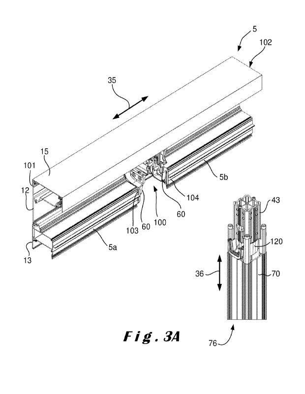
Figure 3A illustrates a beam 5 which extends in a longitudinal
direction, which longitudinal direction 35, in the assembled state of the
terrace
canopy 1, corresponds to a substantially horizontal direction between a first
end
101 and a second end 102. In the beam 5 a recess 100 is arranged, which recess
100 divides the beam 5 into a first beam portion 5a and a second beam portion
5b.
The first beam portion 5a extends between the first end 101 and a third end
103
and the second beam portion 5b extends between the second end 102 and a fourth
end 104. In one embodiment, the recess 100 is formed by removing material from
the beam 5, for example by milling.
A headboard 60 is attached on the third and fourth ends 103, 104.
The headboard 60 is shown in more detail in Figure 7. Five openings 62 are
provided in the headboard, which correspond in positioning to the fastening
channels 115, 116, 208, 219, 220. This allows to attach the headboard 60 to
the
beam portions 5a, 5b by means of five bolts or screws 61 (shown in Figures 5A
and
5B) protruding through openings 62. It will be readily appreciated that more
or less
openings and fastening channels can be used, if desired. Although it is also
possible
to provide the fastening channels in the headboard and to screw the bolts from
the
beams onto the headboard, the embodiment shown is preferred. This is because
the headboard can be made more compact, in particular thinner, if no long
fastening
channels are to be present.
In the embodiment shown, the beams 3, 5 are provided with fastening
channels 115, 116, 117, 208, 219, 220 which are provided in the same place for
each beam. In this way, one and the same headboard 60 can be connected to any
embodiment of external pivot beam 3 and tension beam 5. Alternatively, it is
of
course also possible to provide different headboards 60 for different beams 3,
4, 5
CA 03229903 2024- 2- 23
WO 2023/026178
PCT/IB2022/057877
if the positioning of the fastening channels varies. It is also possible to
vary, within
the same beam, the placement of the fastening channels 115, 116, 117, 208,
219,
220 between the beam portions.
As shown in Figure 7, the headboard 60 is provided at its rear with
5
four openings 64. These form a way of attaching the headboard 60 to the column
2, as described in more detail hereafter.
At the bottom side, the headboard 60 is provided with a passage 65
with a spout-shaped part 63, which connects to the central gutter 27 of the
beams
3, 5. In this way, precipitation collected in the internal gutter 27 can leave
it via
10
passage 65 and spout 63. The external gutter 28 is provided with a closure
(not
shown) at its front end, such that the precipitation collected in the external
gutter 28
cannot but flow to the internal gutter 27. The headboard 60 is also provided
on its
bottom side with a prismatic abutment 59 which contributes to the alignment of
the
headboard 60 with the beam 5. In particular, the stop 59 fits in the cavity 27
as
15
shown in Figure 5B. Figures 5A and 5B also illustrate the provision of a
number of
holders at the front of the headboard 60. In particular, there is an
electronics holder
68 in which the necessary electronics can be placed, for example for driving
the
screen 6. Along the electronics holder 68, a screen holder 69 is present in
which
one end of the screen roll can be placed.
20
Figure 6 illustrates core profile 70 onto which a crown 43 is secured.
In particular, the core profile 70 is provided on its top side with four
openings 74
which are suitable for receiving bolts or screws 44. Correspondingly, the
crown 43
is provided with four legs 520, in particular one leg 520 per corner point of
the crown
43. Openings 521 are provided between the legs 520, which serve as a passage
for precipitation drainage. In particular, as further described, the spout
portion 63 of
a headboard 60 fits into the passageway 521. The legs 520 are hollow such that
the bolts 44 can be screwed through the legs 520 onto the profile 70 to allow
the
crown 43 to be attached directly to the profile 70, as shown in Figure 10. As
a result
of this attachment, the profile 70 and the crown 43 together form the core 76
of the
column 2, as indicated in Figure 3A; this figure also shows the substantially
vertical
direction 36 with which the longitudinal direction of the core 76
substantially
coincides in the assembled state of the terrace canopy 1. It is this core 76
that
CA 03229903 2024- 2- 23
WO 2023/026178
PCT/IB2022/057877
21
serves as a constructive element, in particular as a support for the beams 3,
5. It
will be readily appreciated that other connection means are also possible to
secure
the legs 520 to the top side or the outside of the support column 70, such as
the
use of an elongated rod and securing it by one or more transverse pins or by
welding
the parts together. A threaded rod can also be used as a connection means, in
which case it is, for example, fixedly provided on the top side of the profile
70 and
over which the legs 520 are slid.
The crown 43 serves for attaching the beams 3, 5 to the column 2. To
this end, the crown 43 is provided with openings 45 into which bolts (or
screws)
66 (shown in Figure 3B) are screwed to secure the headboard 60 with the crown
43. In this way, the headboards 60 together with the crown 43 actually form a
connection between the beams 3, 5 and the support column 70, i.e. the crown 43
forms a connection element. Although this connection could be made integrally,
i.e.
one integral element that combines the functionality of the headboards and the
crown, it is preferable to make a division between the crown 43 and the
headboards
60. Firstly, this allows to design of the headboards 60 as a function of the
beam 3,
5 and yet make use of only one crown 43. Furthermore, such an integrated
corner
connection is difficult to place in the recess 100 and to secure it to the
beam portions
5a, 5b.
The main advantage of the structure of column 2 is that the forces by
the beam portions 5a, 5b, for example due to their weight or due to wind load
on a
side wall that is attached to the beam portions 5a, 5b, are transferred
directly to the
core 76, in particular to the crown 43 thereof. In other words, although the
headboards 60 are located between the beam parts 5a, 5b and the crown 43, they
do not serve as a support element to directly transfer the forces to the
support
column 70 which forms the bottom side of the column 2.
The headboard 60 is also provided on its side facing the crown 43
with projection ribs 55 which fit into corresponding grooves 56 in the walls
of the
crown 43. These ribs 55 and grooves 56 form mutually cooperating alignment
means for the correct positioning of the headboard 60 on the connection
element
43. Such mutually cooperating alignment means between a headboard 60 and a
CA 03229903 2024- 2- 23
WO 2023/026178
PCT/IB2022/057877
22
crown 43 have already been described in BE2021/5460, in particular Figures 6A
to
8B therein, which description and figures are thus incorporated herein by
reference.
Figure 6 also illustrates a passage element 120 which serves to pass
collected precipitation between the beam portions 5a, 5b via the internal
gutter 27.
The passage element 120 comprises two spout parts 121 which are opposite each
other and fit in passages 521. The spout 63 of each headboard 60 fits into the
spout
parts 121. For fixedly positioning of the passage element 120, two fastening
channels 122 are provided in which bolts or screws 123 can be placed. These
bolts
or screws 123 are also be secured in fastening channels 124 provided on the
outer
wall of the crown 43. In an alternative embodiment, the passage element is
provided
with an opening to the bottom side which connects to a tube (not shown) in the
cavity 75 of the core profile 70 and thus forms a drainage element for
collected
precipitation. In this way, the supplied precipitate can be diverted to the
bottom side
of the column 2 where it can leave the column 2 through an opening (not
shown).
The cavity 75 can also be used to integrate electrical lines. Although the
cavity 85
between profile 70 and the finishing profiles 78 is preferably used for this
purpose
since this is more easily accessible after mounting. Optionally, the downpipe
49 can
also be omitted such that precipitation flows through the cavity 75 of the
core profile
70.
The situation after placing the beam 5 on the core 76 of the column 2
is shown in Figures 4A and 4B showing the main structural elements of the
final
terrace canopy 1. According to the present invention, the beam 5 is connected
to
the support column 70 via two headboards 60. In particular, each headboard 60
is
connected on its one side to an end 103, 104 of a beam portion 5a, 5b and on
its
other opposite side to the crown 43 which is secured to the support column 70.
In
other words, each headboard 60 is actually attached wall-to-wall both against
a
beam portion 5a, 5b and against the crown 43. Hence, although the headboards
60
are located between the beam portions 5a, 5b and the crown 43, they do not
serve
as a support element to transfer the forces directly to the support column 70,
which
forms the bottom side of the column 2, in contrast to already known fastening
means (for example an L-shaped bracket) which do act as support element.
CA 03229903 2024- 2- 23
WO 2023/026178
PCT/IB2022/057877
23
In order to further increase the strength and bearing capacity of the
beam 5, a portion of the beam 5 continues uninterrupted (i.e. continuously)
over the
core 76 of the column 2. This is best shown in Figure 3B where it is clearly
shown
that the base profile 12 is only partly removed, in particular the upright
wall 200 and
the horizontal wall 201 (see Figure 9) continue uninterrupted. Because these
walls
together form an L-shaped part, this further increases their strength. In the
embodiment shown, only the lower connecting wall 202 of the base profile 12 is
partially interrupted. Also, there are certain walls of the gutter profile 13
that continue
continuously over the column 2, which further contributes to the general
strength of
the beam 3, 5.
Figure 8 shows an example of an external pivot beam 3 supported by
a shifted support column 70. The pivot beam 3 is again divided into two beam
portions 3a, 3b by a recess (not shown) into which the crown 43 fits on top of
the
support column 70. The only difference with the embodiment of Figures 3A to 5B
is
the gutter profile 13 of the beam wherein both an external gutter and an
internal
gutter is present.
In an embodiment, the terrace canopy 1 is mounted by performing the
following steps. In a first phase, the different profiles for the beams 3, 5
and the
column 2 are produced typically via an extrusion process. Also at this stage,
the
crown 43 is extruded and the headboards 60 are manufactured typically via a
moulding process. In a next phase, the necessary openings are provided in the
extruded profiles and the cast headboards. Also the recess 100 can be arranged
therein. Subsequently, the headboards 60 are attached to the beam portions 3a,
3b, 5a, 5b and also headboards (not shown) are attached to the other ends of
the
beam 3, 5. In particular on the base profile 12 and the gutter profile 13. In
this phase,
the crown 43 is also placed on the support column 70 such that the core 76 of
the
column is formed. Thereafter, the headboards 60 (with a part of the beams 3, 5
already thereon) are attached to the core 76, in particular to the crown 43.
Since
the front cover 14 has not yet been placed on the beam 3, 5, it is now
possible to
place bolts through openings 64 in the headboard 60 for screwing it to the
crown 43
through openings 45 therein. In the next phase, the screen roll can be placed
in the
beams 3, 5 and/or another type of wall infill and/or other internal components
such
CA 03229903 2024- 2- 23
WO 2023/026178
PCT/IB2022/057877
24
as the roof covering 7. After all internal components have been installed,
typically
the front cover 14 and/or the cover profile 15 and/or the closing profile 19
are
arranged for finishing the beam.
While certain aspects of the present invention have been described
with respect to specific embodiments, it is to be understood that these
aspects may
be implemented in other forms within the scope of protection as defined by the
claims.
CA 03229903 2024- 2- 23