Note: Descriptions are shown in the official language in which they were submitted.
WO 2023/066606
PCT/EP2022/076669
Device for storing and dispensing a heated liquid and method
for operating such a device
Technical Field
The invention relates to a device for storing and dispensing
a heated liquid comprising an unpressurized hot liquid tank,
whereby the hot liquid tank comprises a heating element for
heating the liquid that is stored within the hot liquid tank,
and whereby the hot liquid tank further comprises a
compensation opening through which pressure balancing with
the environment is enabled, the device further comprising a
dispensing conduit that runs from the hot liquid tank towards
a dispensing unit, the device also comprising a pumping
device for conveying the heated liquid from the hot liquid
tank through the dispensing conduit towards the dispensing
unit, and the dispensing conduit comprising a backflow
preventer that is arranged along the dispensing conduit at a
pressure side of the pumping device and at distance to the
pumping device, whereby the backflow preventer prevents any
liquid to flow backwards through the dispensing conduit
towards the pumping device while the pumping device is not
operated to convey heated liquid towards the dispensing unit.
Background of the invention
Many different embodiments of such devices for storing and
dispensing a heated liquid exist. These devices are known for
1
CA 03229952 2024- 2- 23
WO 2023/066606
PCT/EP2022/076669
and used for providing hot and cold water for human
consumption as well as for domestic use, e.g. for body care,
for cleaning purposes or in kitchens. With common boilers
that provide hot or cold water, a dispensing unit is
connected to a hot liquid tank as well as to a cold water
supply, whereby the dispensing unit provides control elements
for mixing and dispensing hot water provided from the hot
liquid tank and cold water provided from the cold water
supply. Similar or other embodiments of such devices form an
integral part of apparatuses that dispense hot or cold
beverages after and according to a corresponding selection
made by a user.
For many purposes and applications, it is considered
advantageous for the hot liquid tank to be unpressurized,
i.e. to comprise a compensation opening that provides for a
fluidical connection to the environment. Thus, the pressure
within the hot liquid tank equals the atmospheric --------------------
pressure
within the surrounding environment, which allows for a simple
and cost-effective design and manufacture of the hot liquid
tank as well as for a safe and reliable operation of the
device during a long service life of the device. However, as
the hot liquid tank is usually located below a dispensing
unit with a dispensing opening, neither a pressure gradient
nor the gravitational force can be used for causing the
heated liquid to flow from the hot liquid tank into the
dispensing unit and out of a dispensing outlet that is
controlled by or located within the dispensing unit.
Thus, during operation of the device the liquid from the hot
liquid tank, usually heated water, is pumped with the help of
a pumping device from the hot liquid tank towards the
2
CA 03229952 2024- 2- 23
WO 2023/066606
PCT/EP2022/076669
dispensing unit. By activating the dispensing unit, namely by
operating the dispensing unit to dispense heated water from
the hot liquid tank, the pumping device is operated to pump
heated water from the heated liquid tank through the
dispensing conduit into the dispensing unit until the heated
water is dispensed from a dispensing outlet of the dispensing
unit into e.g. a cup or glass or any other container that is
positioned below a dispensing outlet.
The dispensing conduit can be designed to completely run
outside of the hot liquid tank. In order to save heat energy
and to avoid a premature cooling of the liquid which is in
the dispensing conduit before being dispensed through the
dispensing unit, the dispensing unit runs along a section or
predominantly within the hot liquid tank and only exits the
hot liquid tank before running into the dispensing unit that
is usually arranged outside the hot liquid tank. Thus, at
least the section of the di6pensing -------------------------------------------
---- conduit that runs within
the hot liquid tank is heated by the heating element and the
hot liquid within the hot liquid tank.
However, the heating of the liquid within the hot liquid tank
causes some degassing of the heated liquid within the hot
liquid tank, but also within the dispensing conduit.
Furthermore, additional activities like filtering or
descaling the heated liquid may also contribute to a gas
uptake within the heated liquid. An additional source of gas
uptake can be the pumping device that is used for pumping the
heated liquid through the dispensing conduit towards the
dispensing unit. Such gas will be predominantly air from the
environment and air dissolved within the liquid that is
filled into the hot liquid tank. Any residual gas and in
3
CA 03229952 2024- 2- 23
WO 2023/066606
PCT/EP2022/076669
particular any residual air that remains within the
dispensing conduit after the termination of an operation of
the pumping device may interfere with a subsequent operation
of the pumping device. However, appropriate venting of the
dispensing conduit is usually prevented by a backflow
preventer that is arranged along the dispensing conduit at
the pressure side of the pumping device between the pumping
device and the dispensing unit. Such a backflow preventer is
considered mandatory for devices that also feed cold water or
unheated liquid to the dispensing unit that might flow in an
opposite direction through the dispensing conduit, i.e. from
the dispensing unit towards the pumping device and the hot
liquid tank.
Unfortunately, such a backflow preventer not only prevents a
cold liquid to enter into the dispensing conduit and to
backflow towards the pumping device, but also prevents
appropriate venting of the ---------------- dipening conduit to allow any
residual gas within the pressurized side to escape from the
dispensing conduit. Thus, residual gas accumulates within the
dispensing unit and might interfere with the operation of the
pumping device and thus with the operation of the device for
dispensing hot or mixed liquid through the dispensing unit
that at least in part comes from the hot liquid tank.
US 5 367 607 A discloses a brewed beverage maker with
unpressurized holler vessel steam generator tube and common
heating element, which beverage maker has a two-way valve
arranged within the dispensing conduit. In a first position
setting, said valve allows delivering a metered quantity of
water by means of a reciprocating pump, such that steam is
produced without causing water in the boiler vessel to start
4
CA 03229952 2024- 2- 23
WO 2023/066606
PCT/EP2022/076669
boiling. In a second position setting, said valve delivers
hot water by the reciprocating pump to a filter device at a
temperature which can be maintained within close limits of
between 96 C and 97 C, so that overheating of coffee
grounds in the filter device is avoided. In conclusion, by
means of the above described two position settings of said
two-way valve, the water delivered to the dispensing conduit
may be used specifically for generating steam or,
alternatively, for producing hot water.
Accordingly, there is a need for a device as described above
to reduce or to get rid of any residual gas that remains
within the dispensing conduit after each termination of the
operation of the pumping device during a user activated
dispense of heated liquid from the hot liquid tank.
In view of the above discussed background art, it is
considered to be an object of the present invention to
provide a device and a method which allow to reduce or get
rid of any residual gas that remains within the dispensing
conduit after each termination of the operation of the
pumping device during a user activated dispense of heated
liquid from the hot liquid tank.
This object is solved by means of the subject-matters
according to independent claims 1 and 8, and preferred
embodiments thereof are defined in suhclaims 2 to 7.
Summary of the invention
The present invention relates to a device for storing and
dispensing a heated liquid as described above, whereby the
5
CA 03229952 2024- 2- 23
WO 2023/066606
PCT/EP2022/076669
device also comprises a bypass line that branches off from
the dispensing conduit at the pressure side of the pumping
device and that opens into an upper region within the hot
liquid tank that is not filled with the liquid, thereby
providing an opening of the dispensing conduit through which
pressure balancing with the environment is enabled, which
allows for a pressure balancing of the liquid column at the
pressure side of the pumping device with the liquid column at
the intake side of the pumping device after operation of the
pumping device is stopped. It has been found that by
providing such an opening of the dispensing conduit at the
pressure side of the pumping device, the resulting pressure
balancing of the liquid columns at each side of the pumping
device that takes place causes most of the remaining gas to
escape from the dispensing conduit, either by escaping
through the bypass line into the hot liquid tank or by moving
backwards through the intake side of the dispensing conduit
back to the hot liquid tank. All residual gas that eucipe
the dispensing conduit will not contribute to any
interference with the pumping device. Thus, the operation of
the pumping device will be more reliable and more efficient
due to the additional opening of the dispensing unit that is
provided by the bypass line.
During operation of the pumping device, the heated liquid
will be pumped along the pressure side section of the
dispensing conduit and thus will he also pumped into the
bypass line that branches from the dispensing conduit.
However, due to the opening of the bypass line that opens
into the hot liquid tank any heated liquid that flows through
the bypass line will be returned into the hot liquid tank and
will not be wasted or dispensed into the environment. Thus,
6
CA 03229952 2024- 2- 23
WO 2023/066606
PCT/EP2022/076669
making use of such a bypass line that branches off from the
pressure side of the dispensing conduit and that runs back
into the hot liquid tank allows for a safe and efficient
operation of the device without any additional efforts or
limitations for a user. The return of the heated liquid that
runs through the bypass line into the hot liquid tank ensures
that no heated liquid that has been pumped through the
dispensing conduit is wasted or must be collected in a
separate container.
Depending on the arrangement and course of the dispensing
conduit, the liquid that remains within the dispensing
conduit will not be heated by the heating element within the
hot liquid tank but will be the first amount of liquid that
will be transferred through the dispensing conduit to the
dispensing unit. Furthermore, the return flow of at least
some heated liquid that has been pumped towards the
dipening unit but not yet dipened through the ---------------------------------
---- dispensing
outlet reduces the amount of heated liquid that cools down
before the next use of the device, i.e. before a subsequent
operation of the pumping device pumps heated water through
the dispensing conduit towards the dispensing unit.
Thus, the opening within the dispensing conduit that is
formed by the bypass line that opens into an upper region
within the hot liquid tank allows for a pressure balancing
and for a significant reduction of the residua] gas that
remains within the dispensing conduit after each termination
of the operation of the pumping device, and also enhances the
user-friendliness by providing better heated liquid more
quickly to the dispensing unit. Such a device can be used
e.g. as hot water boiler within a household or a building,
7
CA 03229952 2024- 2- 23
WO 2023/066606
PCT/EP2022/076669
the heated liquid being heated water that can be used for
human consumption or sanitary purposes.
According to an embodiment of the invention, the bypass
branch is located outside of the hot liquid tank and above a
top of the hot liquid tank. It is possible to arrange for the
bypass branch next to the backflow preventer that is usually
located outside the hot liquid tank at the pressure side of
the dispensing conduit between the pumping device and the
dispensing unit. The backflow preventer prevents any unwanted
intake into the dispensing conduit and subsequent backflow of
other liquid like e.g. cool water that can also be dispensed
with the dispensing unit. However, the backflow preventer
also prevents any backflow of heated liquid that has been
pumped through the dispensing conduit towards the dispensing
unit, but not yet passed the backflow preventer. Thus, after
termination of the operation of the pumping device, a liquid
column remains trdpped within the ----------------- dipening conduit that
extends from the backflow preventer downwards. The nearer the
bypass branch is located towards the backflow preventer, the
less amount of heated liquid remains trapped within said
section of the dispensing conduit between the bypass branch
and the backflow preventer.
Optionally, the bypass line runs through the compensation
opening of the hot water tank. This allows for an easy and
cost-effective mounting of the bypass line that runs into the
hot liquid tank. As an already existing compensation opening
is used for the introduction of the bypass line into the hot
liquid tank, no additional opening is necessary that would
require additional sealing means. By using the already
existing compensation opening, the additional bypass line
8
CA 03229952 2024- 2- 23
WO 2023/066606
PCT/EP2022/076669
does not affect the safety and reliability of operation of
the device.
It is also possible to retrofit the bypass line to already
existing and used devices with an unpressured hot liquid
tank. Due to the arrangement of the bypass branch outside the
hot liquid tank in combination with the introduction of the
bypass line through the already existing compensation opening
into the hot liquid tank, the efforts that are required for
retrofitting the bypass line can be minimized. It is not
necessary to remove or open the hot liquid tank in order to
provide for the opening within the dispensing conduit that
results in the more reliable and more efficient operation of
the pumping device as well as in the increased user-
friendliness.
In yet another embodiment of the invention, a section of the
dispensing ------------- conduit at the pressure side of the pumping device
runs through the hot liquid tank, and the bypass branch is
located inside of the hot liquid tank and near a top of the
hot liquid tank. The dispensing conduit running through the
hot liquid tank brings several advantages. The heated liquid
that has been pumped into the dispensing conduit but not
dispensed by the dispensing outlet is kept within the hot
liquid tank and will be heated together with the liquid that
remains within the hot liquid tank or that is refilled into
the hot liquid tank after a previous operation of the pumping
device. Furthermore, any leakage along the section of the
dispensing conduit that runs through the hot liquid tank
remains within the hot liquid tank and does not leak into the
environment. By arranging the bypass branch inside of the hot
liquid tank, the heated liquid that flows through the bypass
9
CA 03229952 2024- 2- 23
WO 2023/066606
PCT/EP2022/076669
line out of the dispensing conduit does not leave the hot
liquid tank, which significantly reduces any risk of unwanted
leakage e.g. at the bypass branch or along the bypass line.
Furthermore, there is no additional space requirement for the
device, as the additional bypass line is fully integrated
within the hot liquid tank. As the bypass line opens into the
upper region within the hot liquid tank that is not filled
with liquid during normal operation of the hot liquid tank,
the bypass line does not decrease the usable volume for
storing and heating liquid within the hot liquid tank.
As the bypass line forms an opening of the dispensing
conduit, during operation of the pumping device a part of the
heated liquid that is pumped through the dispensing conduit
will escape through this opening and flow through the bypass
line back into the hot liquid tank. Even though this part of
the heated liquid is not wasted, the flow volume of the
heated liquid that is transferred along the ------------------- dispensing
conduit towards the dispensing unit is reduced. In order to
reduce the amount of heated liquid that is branched off of
the dispensing conduit, it is considered a favorable aspect
of the invention that a flow diameter of the bypass line is
smaller than a flow diameter of the dispensing conduit at the
pressure side of the pumping device. Thus, the fraction of
the heated liquid that is pumped by the pumping device but
returned into the hot liquid tank and thus does not reach the
dispensing unit can he reduced within any further
constructive efforts.
For many applications it is considered favorable that the
flow diameter of the bypass line is less than half of the
flow diameter of the dispensing conduit. Preferably, the flow
CA 03229952 2024- 2- 23
WO 2023/066606
PCT/EP2022/076669
diameter of the bypass line is less than a third or even less
than a quarter of the flow diameter of the dispensing
conduit. Since the flow volume depends on the square of the
flow diameter, a smaller flow diameter of the bypass line
results in a much smaller flow volume that branches off of
the dispensing conduit and that flows through the bypass line
back into the hot liquid tank.
According to a further embodiment of the invention, the
bypass line comprises a backflow preventer that prevents any
flow of liquid from the bypass branch towards an open end of
the bypass line that opens into the hot liquid tank. By
arranging a backflow preventer into the bypass line in such a
manner that any flow of liquid towards the open end of the
bypass line is prevented, this will prevent any branching off
of heated liquid from the dispensing conduit during operation
of the pumping device, resulting in the full flow volume that
is pumped through the --------------- dispensing conduit is transferred to
the dispensing unit. The backflow preventer prevents any
return of heated liquid from the dispensing unit through the
bypass line back into the hot liquid tank. However, the
backflow preventer does not interfere with the pressure
balancing that is enabled by the opening within the
dispensing conduit, as any return flow of heated liquid
within the dispensing conduit back to the pumping device is
not prevented by the backflow preventer within the bypass
line.
According to a favorable aspect of the invention, the pumping
device comprises a rotary pump. A rotary pump enables a
reliable and efficient pumping of a liquid along the
dispensing conduit. The pressure gradient created by a rotary
11
CA 03229952 2024- 2- 23
WO 2023/066606
PCT/EP2022/076669
pump is sufficient for many applications and implementations
of such a device e.g. within a household or such. Usually,
when the rotary pump is not operated and does not pump liquid
from the hot liquid tank towards the dispensing unit, any
liquid can freely flow through the rotary pump. This allows
for a very quick and efficient pressure balancing of the
liquid columns at the pressure side and at the intake side,
which significantly removes any residual gas within the
dispensing conduit and within or near the rotary pump.
The invention also relates to a method for operating such a
device for storing and dispensing a heated liquid, the device
comprising an unpressurized hot liquid tank with a
compensation opening through which pressure balancing with
the environment is enabled, the device further comprising a
dispensing conduit that runs from the hot liquid tank towards
a dispensing unit, the device also comprising a pumping
device for conveying the heated liquid from the hot liquid
tank through the dispensing conduit towards the dispensing
unit, and the dispensing conduit comprising a backflow
preventer that is arranged along the dispensing conduit at a
pressure side of the pumping device and at distance to the
pumping device, whereby the backflow preventer prevents any
liquid to flow backwards through the dispensing conduit
towards the pumping device while the pumping device is not
operated to convey heated liquid towards the dispensing unit.
Usually, heating of the liquid as well as any movement of the
heated liquid and in particular pumping the heated liquid
creates gas bubbles and residual gas within the heated liquid
during operation of such a device. The unwanted accumulation
of such gas bubbles and residual gas may adversely affect the
12
CA 03229952 2024- 2- 23
WO 2023/066606
PCT/EP2022/076669
operation of the device and in particular may interfere with
subsequent operations of the pumping device.
Accordingly, there is also a need for a method for operating
such a device that will reduce any adverse effects caused by
gas bubbles and residual gas within the heated liquid.
According to a favorable aspect of the invention, after each
termination of the operation of the pumping device a pressure
balance between the pressure side and an intake side of the
dispensing conduit is established, resulting in a flow of
heated liquid at the pressure side of the dispensing conduit
backwards towards the pumping device. Establishing a pressure
balance within the dispensing conduit at both sides of the
pumping device causes some heated liquid to flow through the
dispensing conduit. If a pumping device is used that allows
for a throughflow of liquid while the pumping device is not
operated, like e.g. a rotary pump, the heated liquid also
flows through the pumping device. It has been found that such
a flowing movement of heated liquid within the dispensing
conduit and preferably through the pumping device reduces the
accumulation of gas bubbles and residual gas within the
dispensing conduit and within the pumping device, which
enhances the efficiency and user-friendliness of the
operation of the device.
Tn the above described method, the pressure balance is
established by a bypass line that branches off from the
dispensing conduit and opens into an upper region within an
interior of the hot liquid tank that is not filled with
heated liquid, whereby the pressure in this upper region is
the same as in the surrounding area.
13
CA 03229952 2024- 2- 23
WO 2023/066606
PCT/EP2022/076669
Brief description of the drawings
The present invention will be more fully understood, and
further features will become apparent, when reference is made
to the following detailed description and the accompanying
drawings. The drawings are merely representative and are not
intended to limit the scope of the claims. In fact, those of
ordinary skill in the art may appreciate upon reading the
following specification and viewing the present drawings that
various modifications and variations can be made thereto
without deviating from the innovative concepts of the
invention. Like parts depicted in the drawings are referred
to by the same reference numerals.
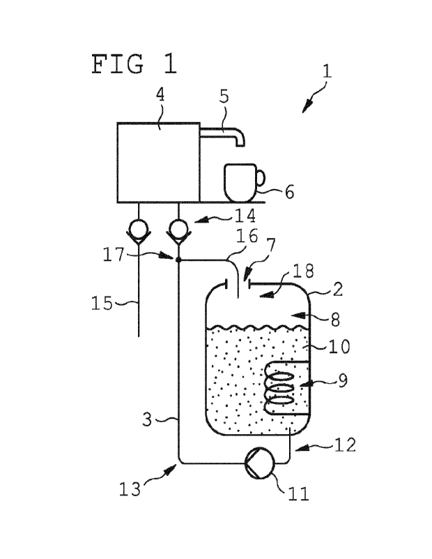
Figure 1 schematically illustrates a device for storing and
dispensing a heated liquid with a hot liquid tank and with a
dispensing ------------- conduit that runs from the hot liquid tank towards
a dispensing unit, whereby a bypass branches off the
dispensing conduit outside of the hot liquid tank and runs
into the hot liquid tank,
Figure 2 schematically illustrates another embodiment of the
device, whereby a section of the dispensing conduit runs
through the hot liquid tank,
Figure 3 schematically illustrates yet another embodiment of
the device, whereby the bypass branch is located within the
hot liquid tank, and
Figure 4 schematically illustrates yet another embodiment of
the device, whereby the bypass line comprises a backflow
14
CA 03229952 2024- 2- 23
WO 2023/066606
PCT/EP2022/076669
preventer that prevents any liquid to flow towards the open
end of the bypass line.
All Figures schematically illustrate a device 1 for storing
and dispensing a heated liquid with a hot liquid tank 2 and
with a dispensing conduit 3 that runs from the hot liquid
tank 2 towards a dispensing unit 4 that enables a user to
operate the device 1 and to dispense some heated liquid
through a dispensing outlet 5 and possibly into a container 6
like e.g. a cup or a glass or a bottle. The hot liquid tank 2
is an unpressurized hot liquid tank 2 that comprises a
compensation opening 7 which provides for a fluidic
connection of an interior 8 of the hot liquid tank 2 with the
environment, resulting in a continuously maintained pressure
balance of equal pressure between the interior 8 and the
environment. A heating element 9 is arranged within the
interior 8 of the hot liquid tank 2 and can be operated to
heat a liquid 10 that has been filled into the interior of
the hot liquid tank 2.
Along the dispensing conduit 3 and usually below the hot
liquid tank 2 there is a pumping device 11. During operation
of the pumping device 11, heated liquid 10 from the hot
liquid tank 2 is pumped through an intake side 12 of the
dispensing conduit 3, through the pumping device 11 and
through a pressure side 13 of the dispensing conduit 3
towards the dispensing unit 4. The pumping device 11 is
preferably a rotary pump, but may be any other pump. The
dispensing conduit 3 may run through the pumping device 11 or
pass along the pumping device 11 with the pumping device 11
being operatively connected to the dispensing conduit 3, like
CA 03229952 2024- 2- 23
WO 2023/066606
PCT/EP2022/076669
e.g. a peristaltic pump that is operatively connected to a
flexible section of the dispensing conduit 3.
A backflow preventer 14 is arranged along the pressure side
13 of the dispensing conduit 3. The backflow preventer 14
prevents any liquid to flow backwards through the pressure
side 13 of the dispensing conduit 3 towards the pumping
device 11 or back into the hot liquid tank 2. External liquid
that will be prevented to flow backwards in the direction of
the hot liquid tank 2 can be e.g. cold water that is also fed
to the dispensing unit 4 by a cold liquid conduit 15. The
arrangement of the backflow preventer 14 provides additional
safety during use or non-use of the device 1. However, the
backflow preventer 14 also prevents any return of heated
liquid 10 back into the hot liquid tank 2 that was previously
pumped by the pumping device 11 from the hot liquid tank 2
towards the dispensing unit 4 but has not yet been dispensed
through the ------------- dispensing outlet 5 of the ---- dispensing unit 4.
Operation of the heating element 9 or of the pumping device
11 usually results in an unwanted accumulation of gas bubbles
and residual gas within the heated liquid 10. Such residual
gas affects the operation of the device 1 and usually
interferes with a reliable and efficient operation of the
pumping device 11. It has been found that by providing for a
pressure balance between the pressure side 13 and the intake
side 12 of the dispensing conduit 3, the volume of residual
gas within the dispensing conduit 3 is significantly reduced
after termination of the operation of the pumping device 11.
In order to allow for such pressure balance, there is a
bypass line 16 that branches off at a bypass branch 17 from
the dispensing conduit 3, that runs into the interior 8 of
16
CA 03229952 2024- 2- 23
WO 2023/066606
PCT/EP2022/076669
the hot liquid tank 2, and that opens into an upper region 18
within the interior 8 of the hot liquid tank 2 that is not
filled by the heated liquid 10 that is stored and heated
within the interior 8 of the hot liquid tank 2. Due to the
hot liquid tank 2 being an unpressurized hot liquid tank 2
and the compensation opening 7 of the hot liquid tank 2, both
the pressure side 13 via the bypass line 16 and the intake
side 12 of the dispensing conduit 3 open into the upper
region 18 within the interior 8 that is at equal pressure
with the environment. Thus, the bypass line 16 enables a
pressure balance within the dispensing conduit 3 that results
in a backflow of heated liquid 10 towards the hot liquid tank
2 after termination of any operation of the pumping device
11, which reduces the amount of residual gas that remains
trapped within the dispensing conduit 3 and that might
interfere with the operation of the device 1 and in
particular with the operation of the pumping device 11.
Figures 1 to 4 schematically illustrated different
arrangements of the dispensing conduit 3 and of the bypass
line 16 that branches off of the dispensing conduit 3. In all
embodiments of the device 1 that are illustrated within the
figures 1 to 4, the dispensing unit 4 is arranged above the
hot liquid tank 2 and the pumping device 11 is arranged below
the hot liquid tank 2. The backflow preventer 14 is located
near the dispensing unit 4 and above the hot liquid tank 2.
However, the device 1 may have any other suitable design or
any other arrangement of some or of all components of the
device 1.
In the exemplary embodiment that is illustrated in Figure 1,
the dispensing conduit 3 runs along the full length of the
17
CA 03229952 2024- 2- 23
WO 2023/066606
PCT/EP2022/076669
dispensing conduit 3 outside of the hot liquid tank 2. The
bypass branch 17 is located outside and above of the hot
liquid tank 2. The bypass line 16 runs through the
compensation opening 7 of the hot liquid tank 2 into the
interior 8 of the hot liquid tank 2 and opens into the upper
region 18 within the interior 8 of the hot liquid tank 2 that
is not filled with heated liquid 10 during normal operation
of the device 1.
Figure 2 illustrates another embodiment of the device 1,
whereby a section 19 of the pressure side 13 of the
dispensing conduit 3 runs through the interior 8 of the hot
liquid tank 2. Thus, this section 19 will also be heated by
the heating element 9. However, the bypass branch 17 is
located outside of the hot liquid tank 2 and the bypass line
16 runs similarly to the bypass line 16 of the embodiment of
Figure 1. Both embodiments of Figure 1 and Figure 2 allow for
easy manufacture and cost-effective retrofitting of the
bypass line 16.
Figure 3 illustrates yet another embodiment of the device 1
with the bypass branch 17 arranged inside of the interior 8
of the hot liquid tank 2. Such a design results in a very
safe and reliable operation of the device 1, as the bypass
line 16 is arranged fully inside of the hot liquid tank 2
which prevents any unwanted leakage of heated liquid 10 along
the bypass line 16 and in particular at the bypass branch 17.
Within yet another embodiment that is shown in Figure 4, the
bypass line 16 comprises a backflow preventer 20 that is
installed into the bypass line 16 in such a manner that the
hackflow preventer 20 prevents any flow of liquid from the
18
CA 03229952 2024- 2- 23
WO 2023/066606
PCT/EP2022/076669
bypass branch 17 towards the upper region 18 within the
interior 8 of the hot liquid tank 2. During operation of the
pumping device 11 heated liquid 10 is pumped along the
pressure side 13 of the dispensing conduit 3, but will not
branch off into the bypass line 16 that is blocked by the
backflow preventer 20. Thus, the full flow volume of heated
liquid 10 that is pumped by the pumping device 11 along the
dispensing conduit 3 will reach the dispensing unit 4 and is
available for being dispensed via the dispensing outlet 5.
19
CA 03229952 2024- 2- 23