Note: Descriptions are shown in the official language in which they were submitted.
CA 03230537 2024-02-28
WO 2023/028652
PCT/AU2022/051065
1
THERMALLY CONDUCTIVE HYDROGELS FOR ACIDIC GAS CAPTURE
FIELD
The present disclosure generally relates to thermally conductive hydrogels. In
particular, the present disclosure relates to thermally conductive hydrogels
comprising
one or more acidic gas absorbents, which can be used to capture one or more
acidic gases
from gaseous streams or atmospheres. The present disclosure also relates to
processes,
methods, systems, uses and apparatuses comprising the thermally conductive
hydrogels
for capturing acidic gases from a gaseous stream or atmosphere.
BACKGROUND
Acidic gases such as carbon dioxide (CO2), sulfur gases (e.g. S02, H2S) can
cause
significant environmental pollution and health risks. There has been
increasing concern
about the damage caused by these contaminants, which has led to an increase
demand to
reduce their emission, including CO2.
Various approaches have been used for acidic gas (e.g. CO2) capture including
the use of liquid and solid-based sorbents. Liquid based sorbents that are
employed
typically comprise groups that chemically react with the acidic gas, including
for
example hydroxide solutions which can capture CO2 from low concentration
streams.
However, the rate of uptake and energy requirements to regenerate the
hydroxide liquid
based sorbents are challenging. In addition, many of the liquid based sorbents
are also
susceptible to oxidation, for example during regeneration, which present
challenges in
terms of long term stability, and are corrosive which limit industrial
applicability.
To address this, various solid materials have been proposed including liquid
sorbents supported on porous supports and porous materials such as metal
organic
frameworks. Whilst these materials offer lower regeneration energies compared
to native
hydroxide solutions, the cost of synthesis can be high and inhibit large scale
production.
Additionally, many of these liquid porous support materials demonstrate
decreased
stability over time and reduced gas absorption performance due to degradation
and/or
.. poor regeneration during acidic gas absorption/desorption. Additionally,
gas absorption
in such solid porous materials is often exothermic and can result in a
significant and
CA 03230537 2024-02-28
WO 2023/028652
PCT/AU2022/051065
2
uneven temperature increase within the solid material. Such prolonged and/or
uneven
heat exposure due to the exothermic gas absorption reaction within the solid
porous
materials can limit the lifetime of the solid porous material due to thermal
degradation.
There is a need for alternative or improved materials for use in acidic gas
capture
which are scalable for industrial application and improved performance and/or
stability
across one or more absorption and desorption cycles (e.g. improved
regeneration).
It will be understood that any prior art publications referred to herein do
not
constitute an admission that any of these documents form part of the common
general
knowledge in the art, in Australia or in any other country.
SUMMARY
The present inventors have undertaken research and development into hydrogels
and methods for removing acidic gases from gaseous streams using hydrogels.
The
hydrogels can be tailored to provide control over the acidic gas absorption
and desorption
(i.e. regeneration) efficiency. In particular, the hydrogels can remove acidic
gases (e.g.
CO2 or H25) from gaseous streams by absorbing the acidic gas within the
hydrogel
thereby removing it from the gaseous stream. The absorbed acidic gas can then
be
harvested (e.g. desorbed) from the hydrogel, and the regenerated hydrogel can
be reused
to absorb more acidic gas from the gaseous stream (e.g. recycled).
In particular, the present inventors have identified that by incorporating a
thermally conductive material on or within the hydrogel, various properties of
the
hydrogel can be improved, including the hydrogels thermal conductivity which
allows
for good control over the acidic gas absorption efficiency and in some
embodiments
faster regeneration, for example by allowing the hydrogel to be heated
efficiently and/or
uniformly. According to at least some embodiments or examples described
herein, such
improved and/or uniform nature of the heating may also improve the lifetime of
the
hydrogel by allowing shorter heating cycles for desorption and as a result
reduced
thermal degradation. The present disclosure described herein can also be
scalable for
industrial application, and may find use particularly in the capture of acidic
gases from
natural gas streams, hydrocarbon sources, industrial effluent gas streams
and/or low
concentration streams (e.g. the atmosphere or closed loop systems). The
present
CA 03230537 2024-02-28
WO 2023/028652
PCT/AU2022/051065
3
hydrogels can combine the advantages of liquids (high selectivity for acidic
gases and
low cost) with those of solids (low regeneration energy and high rate of
uptake).
The hydrogel of the present disclosure comprises a thermally conductive
material.
The thermally conductive material may be a thermally conductive particulate
material.
The thermally conductive material may be interspersed one or within the
hydrogel. The
hydrogel comprises a cross-linked hydrophilic polymer. The thermally
conductive
material may be interspersed within the cross-linked hydrophilic polymer or
may be
interspersed on the surface of the hydrogel. The hydrogel may incorporate one
or more
acidic gas absorbents which are capable of capturing an acidic gas from a
gaseous stream
or atmosphere. The hydrogel may be in the form of a particulate.
In one aspect, there is provided hydrogel comprising a cross-linked
hydrophilic
polymer and a thermally conductive particulate material, wherein the thermally
conductive particulate material is interspersed on or within the hydrogel.
In a related aspect, there is provided a hydrogel for capture of acidic gas
comprising a cross-linked hydrophilic polymer and a thermally conductive
particulate
material, wherein the thermally conductive particulate material is
interspersed on or
within the hydrogel, wherein the hydrogel is in the form of a particulate and
incorporates
one or more acidic gas absorbents.
In one embodiment, the thermally conductive particulate material has a bulk
thermal conductivity of at least 25 W/(m/K) at 25 C, for example between about
25
W/(m/K) and 2000 W/(m/K) at 25 C.
In one embodiment, the hydrogel comprises about 10% w/w to about 80% w/w
of the thermally conductive particulate material based on the total weight of
the hydrogel.
In some embodiments, the thermally conductive particulate material is selected
from one
or more of a carbon based material, a conducting polymer, a metal, a metal
alloy, or a
metalloid or a salt thereof, for example may be selected from one or more of
graphite,
carbon black, carbon nanotubes, or carbon fibres.
In one embodiment, the thermally conductive particulate material is chemically
inert. In a related embodiment, the thermally conductive particulate material
is not
chemically grafting to the cross-linked hydrophilic polymer of the hydrogel.
In a related
CA 03230537 2024-02-28
WO 2023/028652
PCT/AU2022/051065
4
embodiment, the thermally conductive particulate material is not chemically
grafting to
the acidic gas absorbent.
In one embodiment, the cross-linked hydrophilic polymer comprises a
hydrophilic polymer selected from polyamine, a polyacrylamide, a polyacrylate,
a
polyacrylic acid, or a copolymer thereof
In an embodiment, the hydrogel is provided as a plurality of particles. In
other
words, the hydrogel is in the form of a particulate. In one embodiment, the
hydrogel is a
self-supported hydrogel (e.g. the hydrogel is able to maintain its morphology
and
absorptive capacity in the absence of a support material).
In an embodiment, the hydrogel comprises a liquid swelling agent. In one
embodiment, the liquid swelling agent comprises at least one acidic gas
absorbent for
incorporating the acidic gas absorbent within the hydrogel. In one embodiment,
at least
one acidic gas absorbent is incorporated within the hydrogel as part of a
liquid swelling
agent absorbed within the hydrogel. In one embodiment, the liquid swelling
agent
comprises one or more functional groups capable of binding to the acidic gas
by a
chemical process or is a liquid capable of absorbing acidic gas by a physical
process. The
liquid swelling agent may be water or non-aqueous solvent, for example a polar
solvent.
The liquid swelling agent may also be capable of binding or dissolving an
acidic gas, for
example H2S and/or CO2. Alternatively or additionally, the cross-linked
hydrophilic
polymer may comprise one or more functional groups capable of binding to an
acidic gas
(e.g. CO2 or H2S), for example an amine.
In one embodiment, at least one acidic gas absorbent is incorporated within
the
hydrogel as one or more reactive functional groups on the cross-linked
hydrophilic
polymer for binding to the acidic gas.
In another aspect, there is provided a process for preparing a hydrogel
described
above, comprising mixing a solution comprising a hydrophilic polymer and a
cross-
linking agent under conditions effective to cross-link the hydrophilic polymer
to form
the hydrogel, and wherein the process comprises mixing a particulate material
having a
thermal conductivity with the hydrophilic polymer and cross-linking agent or
contacting
the hydrogel with a particulate material under conditions effective to
intersperse the
particulate material on or within the hydrogel.
CA 03230537 2024-02-28
WO 2023/028652
PCT/AU2022/051065
In a related aspect, there is provided a process for preparing a hydrogel as
described above, comprising mixing a solution comprising a hydrophilic
polymer, a
particulate material having a thermal conductivity and a cross-linking agent
under
conditions effective to cross-link the hydrophilic polymer to form the
hydrogel, wherein
5 the particulate material is interspersed on or within the hydrogel.
In another related aspect, there is provided a process for preparing a
hydrogel as
described above, comprising mixing a solution comprising a hydrophilic polymer
and a
cross-linking agent under conditions effective to cross-link the hydrophilic
polymer to
form the hydrogel, and wherein the process comprises contacting the hydrogel
with a
particulate material under conditions effective to intersperse the particulate
material on
or within the hydrogel.
In one embodiment, the process further comprises grinding/crushing the
hydrogel
to form a particulate. In a further embodiment, the hydrogel is ground/crushed
prior to
contact with the thermally conductive particulate material.
In another aspect, there is provided a process for preparing a hydrogel as
described
above, comprising mixing a solution comprising a hydrophilic polymer and a
cross-
linking agent under conditions effective to cross-link the hydrophilic polymer
to form
the hydrogel, and wherein the process comprises mixing a particulate material
having a
thermal conductivity with the hydrophilic polymer and cross-linking agent or
contacting
the hydrogel with a particulate material under conditions effective to
intersperse the
particulate material on or within the hydrogel, wherein the process further
comprises
grinding/crushing the hydrogel to form a particulate.
In another aspect, there is provided a method for removing an acidic gas from
a
gaseous stream or atmosphere, comprising contacting the gaseous stream or
atmosphere
with the hydrogel as described herein to absorb at least some of the acidic
gas from the
gaseous stream or atmosphere into the hydrogel.
In one embodiment, the gaseous stream or atmosphere is selected from the group
consisting of combustion flue gas, a hydrocarbon gas mixture, emission from
cement or
steel production, biogas and ambient air. In one embodiment, the acidic gas is
carbon
dioxide (CO2) or hydrogen sulfide (H2S). In one embodiment, the gaseous stream
or
CA 03230537 2024-02-28
WO 2023/028652
PCT/AU2022/051065
6
atmosphere is a hydrocarbon gas. In one embodiment, the gaseous stream or
atmosphere
is a low CO2 concentration gaseous stream or atmosphere.
In one embodiment, the method further comprises comprises a regeneration
recovery method to desorb the absorbed acidic gas from the hydrogel. In a
further
embodiment, the regeneration recover method comprises heating the hydrogel to
desorb
the absorbed acidic gas from the hydrogel. By heating the hydrogel, the
thermally
conductive particulate material interspersed on or within the hydrogel can
increase the
rate of heat transfer which can translate to more efficient regeneration and
lower
temperatures. The thermally conductive particles may also improve the
mechanical
properties of the hydrogel and help to prevent compaction. According to some
embodiments or examples described herein, the thermally conductive particles
allow the
hydrogel to reach thermal equilibrium more efficiently during one or more
absorption
and desorption cycles.
In one embodiment, the method comprises: providing a chamber enclosing the
hydrogel; passing a flow of the gaseous stream or atmosphere through the
chamber and
contacting the hydrogel to absorb at least some of the acidic gas into the
hydrogel; and
optionally heating the hydrogel to a temperature effective to desorb the
absorbed acidic
gas from the hydrogel; and optionally flushing the desorbed acidic gas from
the chamber.
In another aspect, there is provided an acidic gas removal apparatus
comprising a
chamber enclosing a hydrogel for capture of acidic gas from a gaseous stream
or
atmosphere as described herein, wherein the chamber brings the gaseous stream
or
atmosphere into contact with the hydrogel to absorb at least some of the
acidic gas into
the hydrogel.
In one embodiment, the chamber comprises an inlet through which gaseous
stream or atmosphere can flow to the hydrogel and an outlet through which an
effluent
gaseous stream or atmosphere can flow out from the hydrogel.
It will be appreciated that any one or more of the embodiments and examples
described herein for the hydrogels may also apply to processes for preparing
the
hydrogels, methods for removing acidic gases from gaseous streams or
atmospheres,
and/or apparatuses described herein. Any embodiment herein shall be taken to
apply
mutatis mutandis to any other embodiment unless specifically stated. It will
also be
CA 03230537 2024-02-28
WO 2023/028652
PCT/AU2022/051065
7
appreciated that other aspects, embodiments and examples of the hydrogels,
processes,
methods, and/or apparatuses are described herein.
It will also be appreciated that some features of the hydrogels, processes,
methods,
and/or apparatuses identified in some aspects, embodiments or examples as
described
herein may not be required in all aspects, embodiments or examples as
described herein,
and this specification is to be read in this context. It will also be
appreciated that in the
various aspects, embodiments or examples, the order of method or process steps
may not
be essential and may be varied.
BRIEF DESCRIPTION OF FIGURES
Embodiments of the present disclosure are further described and illustrated as
follows, by way of example only, with reference to the accompanying drawings
in which:
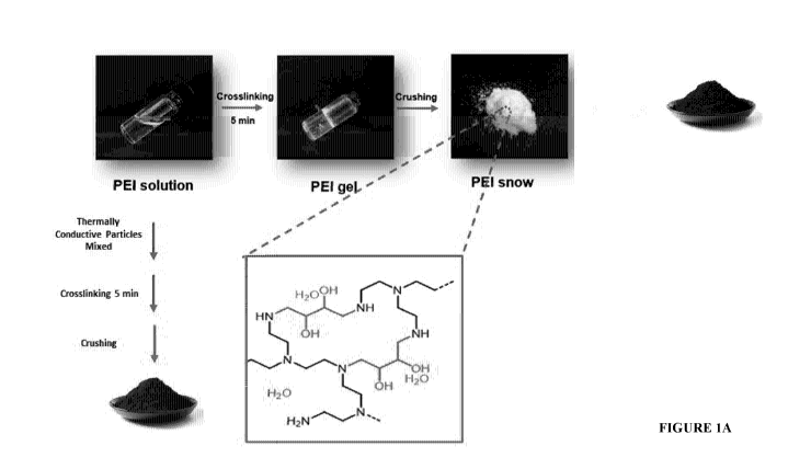
Figure 1A: Illustration of the fabrication and structure of a hydrogel
comprising
thermally conductive particulate material according to one or more
embodiments, where
thermally conductive particles are either added during cross-linking of the
hydrophilic
polymer prior to crushing or to the hydrogel particles following crushing.
Figure 1B: Photo of hydrogel particles comprising thermally conductive
particulate material interspersed on or within the hydrogel (right hand side,
black) or
comprising no thermally conductive particulate material (left hand side,
white).
Figure 2: Schematic of the experimental set-up for evaluating the DAC
performance of the thermally conductive hydrogels. 1. Air compressor 2. Gas
pressure
gauge 3. Mass flow controller 4. Bubbler 5. Sample column 6. Isotopic
analyzer.
Figure 3: Experimental set-up for evaluating the DAC performance at relatively
large scale.
Figure 4: CO2 sorption curves by flowing air through a column of a PEI
hydrogel
comprising no graphite (top), comprising graphite (middle) and regenerated
hydrogels
comprising graphite (bottom).
Figure 5: Depicts an apparatus for performing the method for capture of an
acidic
gas from a gaseous stream or atmosphere, according to some embodiments of the
.. disclosure.
CA 03230537 2024-02-28
WO 2023/028652
PCT/AU2022/051065
8
DETAILED DESCRIPTION
The present disclosure describes the following various non-limiting
embodiments, which relate to investigations undertaken to develop hydrogels
and
methods for removing acidic gases from gaseous streams using hydrogels.
Terms
In the following description, reference is made to the accompanying drawings
which form a part hereof, and which is shown, by way of illustration, several
embodiments. It is understood that other embodiments may be utilized and
structural
changes may be made without departing from the scope of the present
disclosure.
With regards to the definitions provided herein, unless stated otherwise, or
implicit from context, the defined terms and phrases include the provided
meanings.
Unless explicitly stated otherwise, or apparent from context, the terms and
phrases below
do not exclude the meaning that the term or phrase has acquired by a person
skilled in
the relevant art. The definitions are provided to aid in describing particular
embodiments,
and are not intended to limit the claimed invention, because the scope of the
invention is
limited only by the claims. Furthermore, unless otherwise required by context,
singular
terms shall include pluralities and plural terms shall include the singular.
All publications discussed and/or referenced herein are incorporated herein in
their entirety.
Any discussion of documents, acts, materials, devices, articles or the like
which
has been included in the present specification is solely for the purpose of
providing a
context for the present disclosure. It is not to be taken as an admission that
any or all of
these matters form part of the prior art base or were common general knowledge
in the
field relevant to the present disclosure as it existed before the priority
date of each claim
of this application.
Throughout this disclosure, unless specifically stated otherwise or the
context
requires otherwise, reference to a single step, composition of matter, group
of steps or
group of compositions of matter shall be taken to encompass one and a
plurality (i.e., one
or more) of those steps, compositions of matter, groups of steps or groups of
compositions of matter. Thus, as used herein, the singular forms "a", "an" and
"the"
CA 03230537 2024-02-28
WO 2023/028652
PCT/AU2022/051065
9
include plural aspects unless the context clearly dictates otherwise. For
example,
reference to "a" includes a single as well as two or more; reference to "an"
includes a
single as well as two or more; reference to "the" includes a single as well as
two or more
and so forth.
Those skilled in the art will appreciate that the disclosure herein is
susceptible to
variations and modifications other than those specifically described. It is to
be understood
that the disclosure includes all such variations and modifications. The
disclosure also
includes all of the examples, steps, features, methods, hydrogels, processes,
and
compositions, referred to or indicated in this specification, individually or
collectively,
and any and all combinations or any two or more of said steps or features.
The term "and/or", e.g., "X and/or Y" shall be understood to mean either "X
and
Y" or "X or Y" and shall be taken to provide explicit support for both
meanings or for
either meaning.
Unless otherwise indicated, the terms "first," "second," etc. are used herein
merely as labels, and are not intended to impose ordinal, positional, or
hierarchical
requirements on the items to which these terms refer. Moreover, reference to a
"second"
item does not require or preclude the existence of lower-numbered item (e.g.,
a "first"
item) and/or a higher-numbered item (e.g., a "third" item).
As used herein, the phrase "at least one of', when used with a list of items,
means
different combinations of one or more of the listed items may be used and only
one of
the items in the list may be needed. The item may be a particular object,
thing, or
category. In other words, "at least one of' means any combination of items or
number of
items may be used from the list, but not all of the items in the list may be
required. For
example, "at least one of item A, item B, and item C" may mean item A; item A
and item
B; item B; item A, item B, and item C; or item B and item C. In some cases,
"at least one
of item A, item B, and item C" may mean, for example and without limitation,
two of
item A, one of item B, and ten of item C; four of item B and seven of item C;
or some
other suitable combination.
As used herein, the term "about", unless stated to the contrary, typically
refers to
+/- 10%, for example +/- 5%, of the designated value.
CA 03230537 2024-02-28
WO 2023/028652
PCT/AU2022/051065
It is to be appreciated that certain features that are, for clarity, described
herein in
the context of separate embodiments, may also be provided in combination in a
single
embodiment. Conversely, various features that are, for brevity, described in
the context
of a single embodiment, may also be provided separately or in any sub-
combination.
5 Throughout the present specification, various aspects and components of
the
invention can be presented in a range format. The range format is included for
convenience and should not be interpreted as an inflexible limitation on the
scope of the
invention. Accordingly, the description of a range should be considered to
have
specifically disclosed all the possible sub-ranges as well as individual
numerical values
10 within that range, unless specifically indicated. For example,
description of a range such
as from 1 to 5 should be considered to have specifically disclosed sub-ranges
such as
from 1 to 3, from 1 to 4, from 1 to 5, from 2 to 4, from 2 to 5, from 3 to 5
etc., as well as
individual and partial numbers within the recited range, for example, 1, 2, 3,
4, 4.5 or 5,
unless where integers are required or implicit from context. This applies
regardless of the
breadth of the disclosed range. Where specific values are required, these will
be indicated
in the specification.
Throughout this specification the word "comprise", or variations such as
"comprises" or "comprising", will be understood to imply the inclusion of a
stated
element, integer or step, or group of elements, integers or steps, but not the
exclusion of
any other element, integer or step, or group of elements, integers or steps.
The reference to "substantially free" generally refers to the absence of that
compound or component in the hydrogel, gaseous stream or atmosphere other than
any
trace amounts or impurities that may be present, for example this may be an
amount by
weight % in the total hydrogel, gaseous stream or atmosphere of less than
about 1%,
0.1%, 0.01%, 0.001%, or 0.0001%. The hydrogels, gaseous streams or atmosphere
as
described herein may also include, for example, impurities in an amount by
weight % in
the total composition, gaseous stream or atmosphere of less than about 5%, 4%,
3%, 2%,
1%, 0.5%, 0.1%, 0.01%, 0.001%, or 0.0001%. For example, this may be an amount
by
vol. % in the total gaseous stream or atmosphere of less than about 5%, 4%,
3%, 2%,
1%, 0.5%, 0.1%, 0.01%, 0.001%, or 0.0001%. For example, the gaseous streams or
atmospheres as described herein may also include, for example, impurities in
an amount
CA 03230537 2024-02-28
WO 2023/028652
PCT/AU2022/051065
11
by vol. % in the total gaseous stream of less than about 5%, 4%, 3%, 2%, 1%,
0.5%,
0.1%, 0.01%, 0.001%, or 0.0001%. An example of such an impurity is the amount
of
methane (CH4) that may be present in air, being present in an amount of less
than 0.0005
vol. %.
The term "alkyl" or "alkylene" includes straight-chained, branched, and cyclic
alkyl groups and includes both unsubstituted and substituted alkyl groups. In
one
example, the alkyl groups are straight-chained and/or branched, and optionally
interrupted by 1-3 cyclic alkyl groups. Unless otherwise indicated, the alkyl
groups
typically contain from 1 to 30 carbon atoms. The alkyl groups may for example
contain
carbon atoms from 1 to 20, 1 to 15, 1 to 12, 1 to 10, or 1 to 8. Examples of
"alkyl" as
used herein include, but are not limited to, methyl, ethyl, n-propyl. n-butyl,
n-pentyl,
isobutyl, t-butyl, isopropyl, n-octyl, n-heptyl, ethylhexyl, cyclopentyl,
cyclohexyl, cyclo
heptyl, adamantyl, and norbornyl, and the like. Unless otherwise noted, alkyl
groups may
be mono- or polyvalent. The alkyl groups may be optionally substituted and/or
optionally
interrupted by one or more heteroatoms. The alkyl groups may be referred to as
"-alkyl-
"in relation to use as a bivalent or polyvalent linking group.
The term "cycloalkyl" represents a mono-, bicyclic, or tricyclic carbocyclic
ring
system of from about 3 to about 30 carbon atoms, e.g., cyclopropyl,
cyclobutyl,
cyclopentyl, cyclohexyl or cycloheptyl. The cycloalkyl groups may be referred
to as "-
cycloalkyl-" in relation to use as a bivalent or polyvalent linking group.
The term "heteroalkyl" represents an alkyl group as defined supra comprising
one
or more heteroatoms, for example wherein the alkyl group is interrupted with
one or
more (e.g. 1 to 5 or 1 to 3) heteroatoms. It will be appreciated that
heteroatoms may
include 0, N, S, or Si. In one example the heteroatoms is 0. The heteroalkyl
groups may
be referred to as "-heteroalkyl-" in relation to use as a bivalent or
polyvalent linking
group.
The term "aryl" whether used alone, or in compound words such as arylalkyl,
represents: (i) an optionally substituted mono-, bicyclic or tricyclic
aromatic carbocyclic
moiety of about 6 to about 30 carbon atoms, such as phenyl, naphthyl, or
triphenyl; or,
(ii) an optionally substituted partially saturated bicyclic carbocyclic
aromatic ring system
in which an aryl and a cycloalkyl or cycloalkenyl group are fused together to
form a
CA 03230537 2024-02-28
WO 2023/028652
PCT/AU2022/051065
12
cyclic structure such as a tetrahydronaphthyl ring. The aryl groups may be
referred to as
,`-aryl-" in relation to use as a bivalent or polyvalent linking group.
The term "arylalkyl" represents a ¨R¨aryl group where the R group is an alkyl
group, and the alkyl and aryl groups are each defined supra. The arylalkyl
groups may
be referred to as "-arylalkyl-" in relation to use as a bivalent or polyvalent
linking group.
The term "heteroarylalkyl" represents a ¨R¨aryl group where the R group is an
alkyl group, and the alkyl and aryl groups are each defined supra, which is
interrupted
by one or more heteroatoms and optionally substituted as described herein. The
heteroarylalkyl groups may be referred to as "-heteroarylalkyl-" in relation
to use as a
bivalent or polyvalent linking group.
As used herein, the terms "halo" or "halogen", whether employed alone or in
compound words such as haloalkyl, means fluorine, chlorine, bromine or iodine.
As used herein, the term "haloalkyl" means an alkyl group having at least one
halogen substituent, the terms "alkyl" and "halogen" being understood to have
the
meanings outlined above. Similarly, the term "monohaloalkyl" means an alkyl
group
having a single halogen substituent, the term "dihaloalkyl" means an alkyl
group having
two halogen substituents and the term "trihaloalkyl" means an alkyl group
having three
halogen substituents. Examples of monohaloalkyl groups include fluoromethyl,
chloromethyl, bromomethyl, fluoromethyl, fluoropropyl and fluorobutyl groups;
examples of dihaloalkyl groups include difluoromethyl and difluoroethyl
groups;
examples of trihaloalkyl groups include trifluoromethyl and trifluoroethyl
groups.
As used herein, the term "hydroxyl" represents a ¨OH moiety.
As used herein, the term "carboxyl" represents a C=0 moiety.
As used herein, the term "carboxylic acid" represents a -CO2H moiety.
As used herein, the term "nitro" represents a -NO2 moiety.
As used herein, the term "alkanolamine" represents a chemical compound that
contains both hydroxyl (-OH) and amino (e.g. primary -NH2, secondary -NHR
and/or ¨
tertiary -NR2) functional groups on an alkane backbone.
As used herein, the term "polyamine" represents a compound having two or more
amines (e.g. primary ¨NH2, secondary ¨NHR, and/or tertiary -NR2 amine)
functional
groups.
CA 03230537 2024-02-28
WO 2023/028652
PCT/AU2022/051065
13
The term "polyalkylenimine" represents a compound comprising an alkylene
backbone wherein one or more H atoms are substituted for an amino (e.g.
primary -NH2,
secondary -NHR and/or ¨tertiary -NR2) functional groups, and includes
copolymers or
derivatives thereof.
The term "polyacrylamide" represents a polymer comprising two or more
acrylamide monomers, and includes copolymers or derivatives thereof, for
example
poly(acrylamide-co-acrylic acid).
The term "acrylamide" represents a compound with the chemical formula
CH2=CHCNH2 and includes derivatives thereof, for example methacrylamide.
The term "acrylic acid" represents a compound with the formula CH2=CHCOOH
and includes derivatives thereof, for example methacrylic acid.
The term "polyacrylic acid" represents a polymer comprising two or more
acrylic
acid monomers, and includes copolymers or derivatives thereof, for example
poly(methacrylic acid).
The term "acrylate" represents a salt, ester or conjugate base of acrylic
acid. The
acrylate ion is the anion CH2=CHC00-. Examples include methyl acrylate,
potassium
acrylate and sodium acrylate, and methyl methacrylate.
The term "polyacrylate" represents a polymer comprising two or more acrylate
monomers, and includes copolymers or derivatives thereof, for example poly(2-
hydroxyethylmethacrylate).
The term "glycol" represents a class of compounds comprising two or more
hydroxyl (-OH) groups, wherein the hydroxyl groups are attached to a different
carbon
atom.
The term "polyol" represents a compound containing two or more hydroxyl (-
OH) groups.
The term "piperidine" represents a compound having the formula (CH2)5NH.
The term "optionally substituted" means that a functional group is either
substituted or unsubstituted, at any available position. The term
"substituted" as referred
to above or herein may include, but is not limited to, groups or moieties such
as halogen,
hydroxyl, amine, epoxide, nitro, carboxyl, carboxylic acid.
CA 03230537 2024-02-28
WO 2023/028652
PCT/AU2022/051065
14
The term "optionally interrupted" means a chain such as an alkyl chain may be
interrupted by one or more (e.g. 1 to 3) functional groups such as amine,
epoxide,
carboxyl, carboxylic acid, and/or one or more heteroatoms such as N, S, Si, or
0, at any
position in the chain, for example to provide a heteroalkyl group. In one
example,
"optionally interrupted" means a chain such as an alkyl chain is interrupted
by one or
more (e.g. 1 to 3) heteroatoms such as N, S, or 0.
Hydrogels
The present disclosure provides in some embodiments a hydrogel for capture of
acidic gas, comprising a cross-linked hydrophilic polymer and a thermally
conductive
particulate material, wherein the thermally conductive particulate material is
interspersed
on or within the hydrogel, wherein the hydrogel is in the form of a
particulate and
incorporates one or more acidic gas absorbents. In one embodiment, at least
one acidic
gas absorbent is incorporated within the hydrogel as one or more reactive
functional
groups on the cross-linked hydrophilic polymer for binding to the acidic gas
or at least
one acidic gas absorbent is incorporated within the hydrogel as part of a
liquid swelling
agent absorbed within the hydrogel.
The term "hydrogel" refers to a three-dimensional (3D) solid network of cross-
linked hydrophilic polymers that can swell and hold a large amount of water
and other
liquids while maintaining the structure due to chemical or physical cross-
linking of
individual hydrophilic polymer chains. The hydrogel comprises a cross-linked
hydrophilic polymer. The absorbed water/liquid is taken into the cross-linked
hydrophilic
polymeric matrix of the hydrogel through hydrogen bonding rather than being
contained
in pores from which the fluid could be eliminated by squeezing. Unlike other
more
complex inorganic scaffolds and supports, such as zeolites or metal organic
frameworks
(M0Fs), after removing the solvent the hydrogel does not retain a measurable
dry state
porosity.
In one embodiment, the hydrogel has a low porosity. In one embodiment, the
hydrogel does not have a measurable dry state porosity. For example, the
hydrogel may
be essentially non-porous in the dry state. When swollen with a liquid
swelling agent, the
hydrogel can swell beyond the initial dry state pore volume. As a result, the
porosity of
CA 03230537 2024-02-28
WO 2023/028652
PCT/AU2022/051065
the swollen hydrogel increases (i.e. the hydrogel has a "liquid" based
porosity).
According to some embodiments or examples described herein, when swollen with
a
liquid, micro channels of liquid within the hydrogel are created, resulting in
the acidic
gas diffusion distance being significantly reduced allowing for enhanced
sorbent uptake
5 kinetics/efficiency, giving rise to improved performance. If the liquid
is removed from
the hydrogel (for example by freeze drying), the hydrogel does not retain a
measurable
dry state porosity. In contrast, silica supports will take up liquid but do
not swell beyond
the dry state pore volume.
The hydrogel may be characterised by an elastic modulus. For example, the
10 hydrogel may have an elastic modulus of between about 0.1 Pa to about
12,000 Pa. In
some embodiments, the elastic modulus of the hydrogel may be at least about
0.1, 10,
30, 50, 100, 200, 500, 1,000, 2,000, 5,000, 8,000, 10,000 or 12,000 Pa. In
some
embodiments, the elastic modulus of the hydrogel may be less than about
12,000, 10,000,
8,000, 5,000, 2,000, 1,000, 500, 200, 100, 50, 30, 10, or 0.1 Pa. Combinations
of these
15 .. elastic modulus values to form various ranges are also possible, for
example the elastic
modulus of the hydrogel may be between about 100 Pa to about 5,000 Pa. The
hydrogel
may have an elastic modulus of between about 2,000 to about 5,000. In other
embodiments, the elastic modulus of the hydrogel may be at least about 0.1,
10, 30, 50
or 100 Pa. In various embodiments, the elastic modulus of the hydrogel may be
less than
about 12,000, 10,000, 8000, or 6000 Pa. In some embodiments, the elastic
modulus of
the hydrogel may be between about 0.2 Pa to about 12000 Pa, about 0.2 Pa to
about
10000 Pa, about 0.2 Pa to about 5000 Pa, about 1 Pa to about 12000 Pa, or
about 1 Pa to
about 10,000 Pa. In some embodiments, the elastic modulus of the hydrogel may
be
between about 10 Pa to about 12000 Pa, about 10 Pa to about 10,000 Pa, or
about 100 Pa
to about 10,000 Pa. In other embodiments, the elastic modulus of the hydrogel
may be
from between about 0.1 Pa to about 10,000 Pa, about 0.1 Pa to about 5000 Pa,
about 0.1
Pa to about 1000 Pa, about 1 Pa to about 12,000 Pa, about 1 Pa to about 10,000
Pa, about
100 Pa to about 12,000 Pa, about 500 Pa to about 12000 Pa, or about 1000 Pa to
about
12,000 Pa. In other embodiments, the elastic modulus of hydrogel may be
between about
1 Pa to about 5000 Pa, about 10 Pa to about 5000 Pa, or about 100 Pa to about
5000 Pa.
CA 03230537 2024-02-28
WO 2023/028652
PCT/AU2022/051065
16
In some embodiments, the elastic modulus of the hydrogel is less than about
9,000, 5,000,
or 4000 Pa.
The elastic modulus may be determined by a number of suitable techniques,
including using a rheometer, for example a HR-3 Discovery Hybrid Rheometer (TA
Instruments). A Rheometer can be used to control shear stress or shear strain
and/or apply
extensional stress or extensional strain and thereby determine mechanical
properties of a
hydrogel including the modulus of elasticity thereof
The hydrogel may have a surface area of between about 0.1 and 50 m2/g, about
25 m2/g, or 2 and 10 m2/g. The surface area (in m2/g) may be at least about
0.1, 0.5, 1, 2,
3, 4, 5, 6, 7, 8, 9, 10, 15, 20, 25, 30, 35, 40, or 45. The surface area (in
m2/g) may be less
than about 50, 45, 40, 35, 30, 25, 20, 15, 10, 9, 8, 7, 6, 5, 4, 3, 2, or 1.
The surface area
may be in a range provided by any two of these upper and/or lower values. The
surface
area may be provided for the hydrogel in a wet or dry state. It will be
appreciated that the
surface area will depend on particle size. The surface area can be measured
using gas
sorption with nitrogen or particle size analysis through microscopy.
The hydrogel may be provided in a wide range of morphologies. Illustrative
examples of suitable morphologies may include particles, beads, sheets/layers,
cast
blocks, cylinders, discs, porous membranes and monoliths. For example, the
hydrogel
may be provided as a film/coating layer, for example a gel layer where the
gaseous stream
is flowed thereon or through the layer. Such layers may be a provided as a
rolled sheet.
Alternatively, the hydrogel layer may also be provided as a monolith
comprising a
plurality of porous channels, wherein the gaseous stream flows through. Other
layer or
coating morphologies and geometries are also applicable.
In one embodiment, the hydrogel may comprise a plurality of particles i.e. the
hydrogel is in the form of a particulate. The term "particle" or "particulate"
refers to the
form of discrete solid units. The units may take the form of flakes, fibres,
agglomerates,
granules, powders, spheres, pulverized materials or the like, as well as
combinations
thereof The particles may have any desired shape including, but not limited
to, cubic,
rod like, polyhedral, spherical or semi-spherical, rounded or semi-rounded,
angular,
irregular, and so forth. The particle morphology can be determined by any
suitable means
CA 03230537 2024-02-28
WO 2023/028652
PCT/AU2022/051065
17
such as optical microscopy. In one embodiment, the hydrogel may comprise a
plurality
of spherical or substantially spherical beads.
The hydrogel particles may be of any suitable size and/or shape and/or
morphology. For spherical hydrogel particles, the particle size is the
diameter of the
particles. For non-spherical hydrogel particles, the particle size is the
longest cross-
section dimension of the particles. In some embodiments, the hydrogel
particles may
have a particle size in a range from about 0.01 lam to about 10,000 lam, for
example from
about 0.1 lam to about 5000 lam. The hydrogel particles may have a particle
size of at
least about 0.01, 0.1, 1, 10, 20, 50, 100, 200, 300, 400, 500, 700, 1000,
1500, 2000, 5000,
7000, or 10, 000 lam. In other embodiments, the hydrogel particles may have a
particle
size of less than about 10,000, 7000, 5000, 2000, 1500, 1000, 700, 500, 400,
300, 200,
100, 50, 20, 10, 1, 0.1 or 0.01 lam. Combinations of these particle size
values to form
various ranges are also possible, for example the hydrogel particles may have
a particle
size of between about 0.1 lam to about 10,000 lam, between about 1 lam to
about 2000
lam, between about 10 lam to about 2000 lam, between about 10 lam to about 500
lam,
between about 100 lam to about 400 lam, for example between about 200 lam to
about
300 lam.
The hydrogel particles may have a particle size (D5o) of between about 0.01
lam
to about 5000 lam. The hydrogel particles may have a particle size (D5o) of at
least about
0.01, 0.1, 1, 10, 20, 50, 100, 200, 300, 400, 500, 700, 1000, 1500, 2000, or
5000 lam. The
hydrogel particles may have a particle size (D5o) of less than about 5000,
2000, 1500,
1000, 700, 500, 400, 300, 200, 100, 50, 20, 10, 1, 0.1 or 0.01 lam.
Combinations of these
D5o particle size values to form various ranges are also possible, for example
the hydrogel
particles may have a particle size (D5o) of between about 0.1 lam to about
2000 lam or
between about 10 lam to about 500 lam. The D5o particle size is defined such
that 50
volume % of the particles is present in particles having a size less than the
d50 particle
size.
The particle size can be determined by any means known to the skilled person,
such as electron microscopy (SEM or TEM), dynamic light scattering, optical
microscopy or size exclusion methods (such as graduated sieves). The hydrogel
particles
may have a controlled particle size and can maintain their morphology in a
range of
CA 03230537 2024-02-28
WO 2023/028652
PCT/AU2022/051065
18
different environments and shear conditions, for example while in contact with
a gaseous
stream and/or moist or dry environments.
In one embodiment, the hydrogel may be self-supporting. The term 'self-
supporting' as used herein refers to the ability of the hydrogel to maintain
its morphology
in the absence of a support material (e.g. scaffold) such as a porous silica,
zeolite or a
metal organic framework (MOF). For example, the hydrogel may comprise a
plurality of
particles, wherein the particles maintain their morphology in the absence of a
scaffold
support. The self-supported nature of the hydrogel may provide certain
advantages, for
example allows particles of hydrogel to be contacted with the gaseous stream
using a
fluidized bed reactor. Accordingly, in one embodiment, the hydrogel does not
comprise
a separate support structure, such as a separate porous support structure.
This does not
preclude from the hydrogel itself being porous in nature, for example when
swollen with
a liquid swelling agent. Thus it will be understood that, where the hydrogel
is "self-
supporting", there is no support material (e.g. scaffold) exogenous to the
hydrogel.
In a related embodiment, the hydrogel particles are flowable (i.e. exhibits
dry and
powdery properties) allowing it to flow as a loose particulate without being
overly sticky
or rigid. Advantageously, the hydrogel particles remain in the form of a dry,
free-flowing
powder, i.e. without substantial escape of the liquid swelling agent (if
present) to the
outside of the particles, even when acidic gas is absorbed. Because the
hydrogel
particulate is typically a dry, free flowing powder, there is no bulk liquid
phase present
during the absorption. The free-flowing nature of the hydrogel particles may
provide
certain advantages, for example allows hydrogel particles to be contacted with
the
gaseous stream or atmosphere using a fluidized bed reactor.
In some embodiments, the hydrogel may be provided as layer within a column,
wherein the gaseous stream or atmosphere is flowed through the column and
passes
through the hydrogel layer. The layer is not limited to any particular
hydrogel
morphology. In one example, a suitable column may be packed with a plurality
of
hydrogel particles to form a packed-bed with sufficient interstitial space
between
adjacent particles to allow a flow of gas therethrough. Alternatively, the
hydrogel may
.. be provided in flow with the gaseous stream (e.g. a fluidised bed reactor).
CA 03230537 2024-02-28
WO 2023/028652
PCT/AU2022/051065
19
In some embodiments or examples, the hydrogel may be provided as a coating
composition on a substrate. In some embodiments or examples, the substrate may
be
planar, for example a planar sheet. In a particular example, the substrate may
be a flexible
sheet. A planar substrate provides a two sided element onto which the hydrogel
coating
composition can be applied. Each substrate may be coated with the hydrogel
coating
composition on two opposing sides. The planar substrate can have any
configuration. In
some embodiments or examples, the planar substrate may comprise a flat solid
surface.
In other embodiments or examples, the planar substrate may comprise one or
more
apertures, designed to assist gas flow through and around the substrate. In a
particular
-- embodiment or example, the substrate may comprise a mesh, for example,
micro wire
mesh. The use of a mesh provides a multitude of apertures, (e.g. micro size
apertures),
thereby providing a high surface area on which the hydrogel coating
composition can be
applied, whilst also providing a suitable flow path having a reasonably low
pressure drop
across the substrate (relative to the size and configuration of the mesh)
compared to other
-- configurations, for example, packed beds. The hydrogel may be
ground/crushed into a
plurality of particles.
Liquid swelling agent
Hydrogels are capable of absorbing and retaining large amounts of a liquid
-- swelling agent (such as water or a non-aqueous solvent) relative to its
mass. In some
embodiments, the hydrogel is capable of absorbing at least 5 times its own
weight in fluid
up to 300 times its own weight in fluid. The surface area within the hydrogel
may be
increased depending on the degree of swelling of the hydrogel. For example,
the hydrogel
may comprising a liquid swelling agent (such as water or an alkanolamine)
which swells
-- the hydrophilic polymer network of the hydrogels into a more open mobile
structure with
liquid-filled pores which may increase the accessibility of acidic gases (e.g.
CO2 or H2S)
to the reactive functional groups on the hydrophilic polymer and/or on the
liquid swelling
agent. Hydrogels also have has a swelling capacity (sometimes referred to as
the
maximum swelling capacity), which essentially defines the swelling limit of
the
hydrogel.
CA 03230537 2024-02-28
WO 2023/028652
PCT/AU2022/051065
As discussed above, the hydrogel may have a swelling capacity (i.e. is capable
of
absorbing liquid) The typical method to determine this is by taking a known
weight of
the dry hydrogel and swelling in an excess of liquid for a specified period of
time
(typically 48 hours). After which time the excess liquid is removed by
filtration and the
5 hydrogel weight is recorded to determine the swelling ratio. By way of
example, to
determine the swelling capacity of a hydrogel, a known mass (g) of a dry
hydrogel is
dispersed in a liquid swelling agent (such as water) for 48 hours at room
temperature,
after which any non-absorbed free liquid is removed, and the swollen hydrogel
is
weighed. The mass difference between the dry and swollen state of the hydrogel
10 .. corresponds to the amount of the absorbed liquid, which is then
calculated as a grams of
liquid per gram of hydrogel (g/g).
In some embodiments, the hydrogel may have swelling capacity of at least about
1, 5, 10, 20, 30, 40, 50, 60, 70, 80, 90, 100, 150, or 200 g/g. In other
embodiments, the
hydrogel may have a swelling capacity of less than about 200, 150, 100, 90,
80, 70, 60,
15 50, 40, 30, 20, 10, 5 or 1 g/g. Combinations of these swelling capacity
values to form
various ranges are also possible, for example the hydrogel may have a swelling
capacity
of between about 20 g/g to about 100 g/g. The swelling capacity can also be
provided as
a percentage, for example a swelling capacity of 0.5 g/g equates to 50% (i.e.
the hydrogel
swells 50%).
20 The swelling capacity of the hydrogel can also vary depending on the
liquid
swelling agent. For example, the hydrogel may have a different swelling
capacity with
water as the liquid swelling agent compared to glycerol as the liquid swelling
agent. For
example, the hydrogel may have a swelling capacity of between about 1 g/g to
about 200
g/g, for example between about 20 g/g to about 200 g/g water. In some
embodiments,
the hydrogel may have swelling capacity of at least about 1, 5, 10, 20, 30,
40, 50, 60, 70,
80, 90, 100, 150, or 200 g/g water. In other embodiments, the hydrogel may
have a
swelling capacity of less than about 200, 150, 100, 90, 80, 70, 60, 50, 40,
30, 20, 10, 5
or 1 g/g water. Combinations of these swelling capacity values to form various
ranges
are also possible, for example the hydrogel may have a swelling capacity of
between
.. about 20 g/g to about 100 g/g water.
CA 03230537 2024-02-28
WO 2023/028652
PCT/AU2022/051065
21
In another example, the hydrogel may have a swelling capacity of between about
1 g/g to about 200 g/g, for example between about 20 g/g to about 200 g/g
glycerol. In
some embodiments, the hydrogel may have swelling capacity of at least about
0.5, 1, 5,
10, 20, 30, 40, 50, 60, 70, 80, 90, 100, 150, or 200 g/g glycerol. In other
embodiments,
the hydrogel may have a swelling capacity of less than about 200, 150, 100,
90, 80, 70,
60, 50, 40, 30, 20, 10, 5 1, or 0.5 g/g glycerol. Combinations of these
swelling capacity
values to form various ranges are also possible, for example the hydrogel may
have a
swelling capacity of between about 1 g/g to about 200 g/g, or between about 20
g/g to
about 100 g/g glycerol. The swelling capacity can also be provided as a
percentage, for
example a swelling capacity of 0.5 g/g equates to 50% (i.e. the hydrogel
swells 50%).
In some embodiments, the hydrogel is swollen with a liquid swelling agent to
between about 60% to about 99% of the hydrogels swelling capacity. For
example, the
hydrogel may be swollen to at least about 60, 70, 80, 90, 95, 98, or 99% of
the hydrogels
swelling capacity. The hydrogel may be swollen to less than about 99, 98, 95,
90, 80, 70,
or 60% of the hydrogels swelling capacity. Combinations of these % values to
form
various ranges are also possible, for example the hydrogel may be swollen to
between
about 70% to about 98% of the hydrogels swelling capacity, for example between
about
80% to about 95% of the hydrogels swelling capacity.
In one embodiment, the amount of liquid swelling agent absorbed within the
hydrogel does not exceed the swelling capacity of the hydrogel. According to
some
embodiments or examples, by not exceeding and/or operating below the hydrogels
swelling capacity, the hydrogel exhibits "dry" and "powdery" characteristics
and when
in particulate form is capable of flowing, even with the presence of liquid
swelling agent
absorbed therein. By ensuring that the amount of absorbed liquid, and any
moisture from
the gaseous stream that may also be absorbed when in use, is at or near the
hydrogel
swelling capacity whilst not exceeding the same, the amount of liquid within
each
particle can be maximised to allow for increased acidic gas absorption, whilst
retaining
the hydrogel's "dry" and "powdery" characteristics.
The hydrogel is capable of swelling and retaining the absorbed liquid swelling
agent within the hydrogel. The hydrogel may be capable of swelling and
retaining about
0.5 wt.% to about 99 wt.% liquid swelling agent based on the total weight of
the hydrogel
CA 03230537 2024-02-28
WO 2023/028652
PCT/AU2022/051065
22
(e.g. the weight of the hydrogel and any liquid swelling agent absorbed
therein). The
liquid swelling agent may be strongly or weakly bound to the cross-linked
hydrophilic
polymer network within the hydrogel or may be non-bound. The amount of liquid
swelling agent in the hydrogel can vary depending on the degree of swelling or
dehydration of the hydrogel. For example, the hydrogel may comprise between
0.5 wt.%
to about 99 wt.% liquid swelling agent based on the total weight of the
hydrogel.
In some embodiments, the hydrogel may comprise at least about 0.5, 1, 5, 10,
20,
30, 40, 50, 60, 70, 80, 90, or 99 wt.% liquid swelling agent based on the
total weight of
the hydrogel. In some embodiments, the hydrogel may comprise less than about
99, 90,
80, 70, 60, 50, 40, 30, 20, 10, 5, 1, or 0.5 wt.% liquid swelling agent based
on the total
weight of the hydrogel. Combinations of these wt. % values to form various
ranges are
also possible, for example the hydrogel may comprise between about 30 wt. % to
about
99 wt.% liquid swelling agent, for example between about 40 wt.% to about 99
wt.%
liquid swelling agent based on the total weight of the hydrogel.
In some embodiments, the hydrogel comprises between about 50 wt. % to about
99 wt. % liquid swelling agent based on the total weight of the hydrogel. In
some
embodiments, the hydrogel comprises at least about 50, 55, 60, 65, 70, 75, 80,
85, 90,
95, or 99 wt. % liquid swelling agent based on the total weight of the
hydrogel. In other
embodiments, the hydrogel comprises less than about 99, 95, 90, 85, 80, 75,
70, 65, 60,
55, or 55 wt. % liquid swelling agent based on the total weight of the
hydrogel t.
Combinations of these wt. % values to form various ranges are also possible,
for example
the hydrogel comprises between about 85 wt.% to about 98 wt.% liquid swelling
agent
based on the total weight of the hydrogel. Suitable liquid swelling agents are
described
herein.
In some embodiments, the weight ratio % of absorbed liquid swelling agent to
hydrogel may be at least about 1:5, 1:4, 1:3, 1:2, 1:1, 1.5:1, 2:1, 2:5:1,
3:1, 3.5:1, 4:1,
4.5:1 or 5:1. In some embodiments, the weight ratio % of absorbed liquid
swelling agent
to hydrogel may be less than about 5:1, 4.5:1, 4:1, 3.5:1, 3:1, 2.5:1, 2:1,
1.5:1, 1:1, 1:2,
1:3, 1:4 or 1:5. The weight ratio % of absorbed liquid swelling agent to
hydrogel may be
a range provided by any two of these upper and/or lower values, for example
the between
about 1:1 to about 5:1. According to some embodiments or examples, this ratio
may
CA 03230537 2024-02-28
WO 2023/028652
PCT/AU2022/051065
23
provide one or more advantages, including maximising the amount of reactive
functional
groups for capture of the acidic gas (e.g. swells the hydrophilic polymer
network of the
hydrogels into a more open mobile structure with liquid-filled pores which may
increase
the accessibility of acidic gases (e.g. CO2 or H2S) to the reactive functional
groups on
the hydrophilic polymer and/or on the liquid swelling agent) whilst
maintaining the
powdery "dry" characteristics of the hydrogel, which when in particulate form
allows
them to flow for example in a fluidised bed reactor.
Alternatively, the hydrogel may be in a dry or dehydrated state where some of
the
absorbed liquid swelling agent is removed or evaporated. A dry hydrogel (also
known as
a dehydrated hydrogel) may comprise about 0.01% to about 20% liquid swelling
agent
based on the total weight of the hydrogel, for example between about 0.5 wt.%
to about
10 wt.% liquid swelling agent based on the total weight of the hydrogel.
In one embodiment, the liquid swelling agent is a non-polymeric liquid with a
molecular weight of below 500 g/mol. It is challenging to load high amounts of
polymeric liquid swelling agent into a hydrogel because such materials are
either solids
or high viscosity liquids. Moreover, the diffusion of acidic gases into the
hydrogel
composition limits CO2 absorption capacity even at relatively low loadings of
a
polymeric liquid swelling agents. In some embodiments, therefore, the
molecular weight
of the liquid swelling agent is less than 500 g/mol, preferably less than 200
g/mol.
The liquid swelling agent may have low volatility. For example, the liquid
swelling agent may have a boiling point of at least about 100, 120, 140, 160,
200, 220,
240, 260, 280, or 300 C. The liquid swelling agent may have a boiling point of
less than
about 300, 280, 260, 240, 220, 200, 160, 140, 120, or 100 C. Combinations of
these
boiling points to provide various ranges are also possible, for example the
liquid swelling
agent has a boiling point of between about 100 C to about 300 C. The boiling
point of
the liquid swelling agent can vary depending on the liquid swelling agent, for
example
water has a boiling point of about 100 C, glycerol has a boiling point of
about 290 C,
and monoethylene glycol (MEG) has a boiling point of about 198 C. According to
at
least some embodiments or examples described herein, high boiling point
solvents may
result in lower evaporation loss of the solvent when the hydrogel comprising
the solved
as a liquid swelling agent is subjected to regeneration (e.g. heating with
steam) to remove
CA 03230537 2024-02-28
WO 2023/028652
PCT/AU2022/051065
24
captured acidic gases (e.g. CO2 or H2S), resulting in the acidic gas being
selectively
removed before the solvent evaporates.
The liquid swelling agent may be water, a non-aqueous solvent, or a
combination
thereof In one embodiment, the liquid swelling agent is a non-aqueous solvent.
The non-
aqueous solvent may be a polar solvent. In one embodiment, the liquid swelling
agent
may comprise one or more functional groups capable of binding to an acidic gas
(e.g.
CO2 or H2S), for example an amine. Alternatively or additionally, the liquid
swelling
agent may comprise a group that can help to dissolve the acidic gases (e.g.
CO2 or H2S),
for example hydroxyl groups.
In one embodiment, at least one acidic gas absorbent is incorporated within
the
hydrogel as part of a liquid swelling agent absorbed within the hydrogel. For
example,
the liquid swelling agent comprises an acidic gas absorbent for incorporating
at least one
acidic gas absorbent within the hydrogel. In one embodiment, the liquid
swelling agent
comprises one or more functional groups capable of binding to the acidic gas
by a
chemical process or is a liquid capable of absorbing acidic gas by a physical
process.
In one embodiment, the liquid swelling agent comprises one or more functional
groups capable of binding to the acidic gas by a chemical process, for example
by binding
to the acidic gas via one or more functional groups (e.g. amines) present in
the liquid
swelling agent. The term "by a chemical process" means the preferential
absorption of
the liquid swelling agent to an acidic gas within a gaseous stream or
atmosphere by means
of a chemical reaction wherein a charge is transferred, for example by binding
to the
acidic gas via one or more functional groups (e.g. amines) present in liquid
swelling
agent. Suitable liquids that are capable of absorbing the acid gas by a
chemical process
include, but are not limited to, amines including alkanolamines, alkylamines,
and
alkyloxyamines, piperidine and its derivatives, piperazine and its
derivatives, pyridine
and its derivatives, and mixtures thereof, as described herein.
Examples of suitable amines include primary amines such as monoethanolamine,
ethylenediamine, 2-amino-2-methylpropanol, 2-amino-2-methyl- ethanolamine and
benzylamine; secondary amines such as N-methylethanolamine, piperazine,
piperidine
and substituted piperidine, N-alkyl derivatives of 2- amino-l-propanol (AP),
especially
2-N-methylamino-l-propanol (MAP), 2-N- methylamino-2-methyl-l-propanol (MAMP),
CA 03230537 2024-02-28
WO 2023/028652
PCT/AU2022/051065
as well as derivatives with two or more hydroxyl groups and/or ether
derivatives,
diethanolamine, diglycolamine and diisopropanolamine; and tertiary amines such
as N-
methyldiethanolamine, and amino acids such as taurine, sarcosine, alanine, 2-
amino-2-
methyl-l-propanol (AMP), 3-piperidinemethanol, 3 -pipe
ridineethanol, 2-
5
piperidinemethanol, 2-piperidineethanol, N-piperidinemethanol, N-
piperidineethanol, 2-
methylaminoethanol, N,N-dimethylaminoethanol and 3 -
quinuclidinol .
monoethanolamine, diethanolamine, aminoethylethanolamine,
diglycolamine,
piperazine, N- aminoethylpiperazine, N-(2-hydroxyethyl)piperazine and
morpholine.
The liquid swelling agent may be selected from the group consisting of water,
10 alcohols, polyol compounds, glycols, amines (e.g. alkanolamines,
alkylamines,
alkyloxyamines), piperidines, piperazines, pyridines, pyrrolidones, and
derivatives or
combinations thereof Suitable alkanolamines may include monoethanolamine,
diethanolamine, methyldiethanolamine, diisopropanolamine, N-
ethylmonoethanolamine
and aminoethoxyethanol. Suitable alkylamines may include an ethyleneamine, for
15 example tetraethylpentamine (TEPA). Suitable glycols may include ethylene
glycol,
monoethylene glycol, diethylene glycol, triethylene glycol, propylene glycol,
propanediol, butylene glycol, Triethylene glycol, polyethylene glycol, and
diglyme.
Suitable alcohols may include 2-ethyoxyethanol, 2-methoxyethanol. Suitable
polyol
compounds may include glycerol. Suitable piperidines include piperidine, 2-
20 methylpiperidine, 3-methylpiperidine, 4-methylpiperidine, 2-
piperidineethanol (PE), 3-
piperidinemthanol, and 4-piperidinemthanol. The liquid swelling agent may
comprise
any one or more of the above liquids. In one embodiment, the liquid swelling
agent is
selected from the group consisting of alkylamines, alkanolamines, and glycols,
and
combinations thereof
25 In some
embodiments, the liquid swelling agent may be selected from the group
consisting of water, monoethanolamine, diethanolamine, me thyldiethanolamine,
diisopropanolamine, N-ethylmonoethanolamine, aminoethoxyethanol, ethylene
glycol,
Triethylene glycol, monoethylene glycol, diethylene glycol, triethylene
glycol,
propylene glycol, propanediol, butylene glycol, polyethylene glycol, glycerol,
diglyme,
2-ethyoxyethanol, 2-methoxyethanol, glycerol, 2-methylpiperidine, 3-
methylpiperidine,
CA 03230537 2024-02-28
WO 2023/028652
PCT/AU2022/051065
26
4-methylpiperidine, 2-piperidineethanol (PE), 3 -piperidinemthanol, and 4-
piperidinemthanol.
In one embodiment, the liquid swelling agent is a liquid capable of absorbing
acidic gas by a physical process. The term "by a physical process" means the
absorption
of the acidic gas from a gaseous stream or atmosphere by physical
characteristics and not
by means of a chemical reaction (e.g. the liquid swelling agent does not
chemically bind
to the acidic gas but can dissolve it). Suitable liquids capable of absorbing
acidic gases
(e.g. CO2 or H2S) by a physical process (e.g. do not chemically bind to the
acidic gas but
can dissolve it) include but are not limited to polyethylene glycols, alkyl
ethers of
polyethylene glycols and in particular dialkyl ethers such as dimethyl ethers
of
polyethylene glycol, N-methylpyrrolidone, propylene carbonate, methanol,
sulfolane
(tetrahydrothiophenedioxide), estasolvan (tributyl phosphate), imidazoles,
ionic liquids,
primary amines, secondary amines, tertiary amines, sterically hindered amines,
and
mixtures thereof Specific examples of commercially available physical solvents
include
dimethyl ether (DEPG) of polyethylene glycol (UOP LLC; Des Plaines, IL) used
in the
SELEXOL process; methanol used in the RECTISOL process (Lurgi AG; Frankfurt,
Germany); RECTISOL n- methyl-2-pyrrolidone (NMP) (Lurgi AG); and propylene
carbonate (PC) used in the FLUOR SOLVENT process (Fluor Corp).
In one embodiment, the liquid swelling agent is selected from the group
consisting
of water, monoethylene glycol, polyethyleneglycol, glycerol, 2-methoxyethanol,
2-
ethoxyethanol, monoethanolamine, diethanolamine, me
thyldiethanolamine,
diisopropanolamine, and aminoethoxyethanol, and combinations thereof. In one
embodiment, the liquid swelling agent is water, glycerol, monoethanolamine,
diethanolamine, 2-piperidineethanol, ethylene glycol, Triethylene glycol, or
monoethyleneglycol (MEG) or combinations thereof
In some embodiments, the liquid swelling agent is capable of absorbing acidic
gases (e.g. CO2 or H25) when contacted with a gaseous stream or atmosphere.
Suitable
liquid swelling agents that are capable of absorbing acidic gases (e.g. CO2 or
H25)
include one or more of the liquid swelling agents described herein. In some
embodiments, the liquid swelling agent may absorb acidic gases (e.g. CO2 or
H25) by a
chemical or physical process. In some embodiments, the liquid swelling agent
comprises
CA 03230537 2024-02-28
WO 2023/028652
PCT/AU2022/051065
27
functional groups capable of binding to acidic gases (e.g. CO2 or H2S). For
example, the
liquid swelling agent may comprise one or more amine groups, such as a primary
amine
(-NH2) or secondary amine group (-NH-). Such amine groups are H25 and CO2-
phillic
and readily react and bind with H25 and CO2. In some embodiments, the liquid
swelling
agent comprises one or more amine groups amine, such as an alkanolamine. In
another
example, the liquid swelling agent comprises two or more (-OH) groups which
are
capable of physically dissolving acidic gases (e.g. CO2 or H25), for example a
glycol, a
polyol or dimethyl ethers as described herein.
In some embodiments, the hydrogel may comprise at least about 0.5, 1, 5, 10,
20,
30, 40, 50, 60, 70, 80, 90, or 99 wt.% water. In some embodiments, the
hydrogel may
comprise less than about 99, 90, 80, 70, 60, 50, 40, 30, 20, 10, 5, 1, or 0.5
wt.% water.
Combinations of these wt. % values to form various ranges are also possible,
for example
the hydrogel may comprise between about 40 wt. % to about 99 wt.% water. The
water
may have a degree of salinity, e.g. may be a brine or salt water.
In some embodiments, the hydrogel may comprise at least about 0.5, 1, 5, 10,
20,
30, 40, 50, 60, 70, 80, 90, or 99 wt.% glycerol. In some embodiments, the
hydrogel may
comprise less than about 99, 90, 80, 70, 60, 50, 40, 30, 20, 10, 5, 1, or 0.5
wt.% glycerol.
Combinations of these wt. % values to form various ranges are also possible,
for example
the hydrogel may comprise between about 40 wt. % to about 99 wt.% glycerol.
In some embodiments, the hydrogel may comprise at least about 0.5, 1, 5, 10,
20,
30, 40, 50, 60, 70, 80, 90, or 99 wt.% monoethyleneglycol (MEG). In some
embodiments,
the hydrogel may comprise less than about 99, 90, 80, 70, 60, 50, 40, 30, 20,
10, 5, 1, or
0.5 wt.% monoethyleneglycol (MEG). Combinations of these wt. % values to form
various ranges are also possible, for example the hydrogel may comprise
between about
40 wt. % to about 99 wt.% monoethyleneglycol (MEG).
In some embodiments, the hydrogel may comprise at least about 0.5, 1, 5, 10,
20,
30, 40, 50, 60, 70, 80, 90, or 99 wt.% of an alkanolamine. In some
embodiments, the
hydrogel may comprise less than about 99, 90, 80, 70, 60, 50, 40, 30, 20, 10,
5, 1, or 0.5
wt.% of an alkanolamine. Combinations of these wt. % values to form various
ranges are
also possible, for example the hydrogel may comprise between about 40 wt. % to
about
99 wt.% of an alkanolamine. Suitable alkanolamines are described herein.
CA 03230537 2024-02-28
WO 2023/028652
PCT/AU2022/051065
28
In some embodiments, the hydrogel may comprise at least about 0.5, 1, 5, 10,
20,
30, 40, 50, 60, 70, 80, 90, or 99 wt.% of a glycol. In some embodiments, the
hydrogel
may comprise less than about 99, 90, 80, 70, 60, 50, 40, 30, 20, 10, 5, 1, or
0.5 wt.% of
a glycol. Combinations of these wt. % values to form various ranges are also
possible,
for example the hydrogel may comprise between about 40 wt. % to about 99 wt.%
of a
glycol. Suitable glycols are described herein.
In some embodiments, the hydrogel may comprise at least about 0.5, 1, 5, 10,
20,
30, 40, 50, 60, 70, 80, 90, or 99 wt.% a piperidine. In some embodiments, the
hydrogel
may comprise less than about 99, 90, 80, 70, 60, 50, 40, 30, 20, 10, 5, 1, or
0.5 wt.% a
piperidine. Combinations of these wt. % values to form various ranges are also
possible,
for example the hydrogel may comprise between about 40 wt. % to about 99 wt.%
a
piperidine. Suitable piperidines are described herein.
The liquid swelling agent may further comprise an amino acid salt. The
incorporation of an amino acid salt within the liquid swelling agent can
improve acidic
gas absorption. Due to the presence of the amino functional group, CO2 can
bind with
the amino acid salt thus increasing CO2 absorption. The amino acid salt may
comprise
any suitable amino acid or derivative thereof, for example glycine, proline,
sarcosine, or
taurine. The amino acid salt may comprise any suitable salt, including
ammonium salts,
alkali metal salts, for example those of potassium and sodium, alkaline earth
metal salts,
for example those of calcium and magnesium. The amino acid salt may be
potassium
glycinate, potassium sarcosinate, potassium proline, or isopropyl glycinate.
In one
embodiment, the amino acid salt is potassium sarcosinate.
The liquid swelling agent may also increase the thermal conductivity of the
hydrogel. The one or more advantages of increasing the thermal conductivity of
the
hydrogel are described herein.
The hydrogel may further comprise a chelator (i.e. a chelating agent). The
chelator
can improve the stability of the hydrogel by chelating to any residual metal
that may be
present within the hydrophilic polymer, for example one or more contaminants
such as
lead or copper. The chelator may be a phosphate salt, for example potassium
phosphate
or sodium phosphate. In one embodiment, the chelator is sodium phosphate.
Other
CA 03230537 2024-02-28
WO 2023/028652
PCT/AU2022/051065
29
suitable chelators can include EDTA, deferoxamine mesylate salt, chromium
picolinate,
zinc picolinate and pentetic acid.
The absorptive capacity of the hydrogel may be enhanced by incorporating a
hygroscopic salt into the hydrogel, either as part of the cross-linked
hydrophilic polymer
and/or as part of the liquid swelling agent, or as a separate aqueous solution
that is
absorbed into the hydrogel. The hygroscopic salt may be a monovalent salt such
as
lithium chloride, lithium bromide or sodium chloride, or a divalent salt such
as calcium
chloride, calcium sulphate. The hygroscopic salt may be present in the cross-
linked
polymer network in any amount up to saturation thereof
Where a hydrogel comprises a non-aqueous solvent liquid swelling agent, the
hydrogel may be prepared using the non-aqueous solvent as the dispersion
medium (e.g.
the hydrophilic polymer is dispersed in the non-aqueous liquid swelling agent,
and cross-
linked therein to form the hydrogel). Alternatively, the hydrogel may be
prepared using
water as the dispersion medium, and is subsequently dried/dehydrated to remove
the
absorbed water, and then the non-aqueous solvent is added to the hydrogel and
absorbed
therein. For example, the dried hydrogel may be immersed in the non-aqueous
solvent,
and left for a period of time to infuse/absorb the non-aqueous solvent.
Alternatively, the
hydrogel may be a commercially available hydrogel (e.g. Bio-Gel P
polyacrylamide
beads) which are subsequently added to the liquid swelling agent to be
absorbed therein.
Thermally conductive particulate material
The hydrogel comprises a thermally conductive particulate material. The
thermally conductive particulate material may be interspersed on or within the
hydrogel.
For example, the thermally conductive particulate material may be interspersed
within
the cross-linked hydrophilic polymer forming the hydrogel. Alternatively or
additionally,
the thermally conductive particulate material may be interspersed on or within
the surface
of the hydrogel.
In some embodiments, the interspersed thermally conductive particulate
material
on or within the hydrogel may be provided by at least one of:
a) thermally conductive particulate material intercalated, interspersed or
embedded within the hydrogel;
CA 03230537 2024-02-28
WO 2023/028652
PCT/AU2022/051065
b) intercalated, interspersed or embedded into the surface of the hydrogel;
and
c) an additional coating on the surface of the hydrogel.
In some embodiments, the thermally conductive particulate material is not
chemically grafted to the cross-linked hydrophilic polymer of the hydrogel
(i.e. there is
5 no chemical bonding between the hydrophilic polymer matrix and the thermally
conductive particulate material).
In one embodiment, the thermally conductive particulate material is not
chemically grafted to the one or more reactive functional groups on the cross-
linked
hydrophilic polymer of the hydrogel. For example, where the hydrogel comprises
a cross-
10 linked polyamine (such as a cross-linked polyethylenimine), in some
embodiments the
thermally conductive particulate material is not chemically grafted to one or
more amine
groups on the cross-linked polyethylenimine. According to some embodiments or
examples, the lack of chemical grafting may arise in part due to the thermally
conductive
particulate material being chemically inert. For example, graphite is
chemically inert and
15 lacks reactive groups capable of chemically grafting to one or more
functional groups,
such as amines, on the cross-linked hydrophilic polymer. In contrast, graphene
oxide
comprising reactive epoxide and carboxylic acid groups capable of reacting
with amine
groups. Such chemical grafting to free amine groups is expected may reduce the
acidic
gas absorption capacity of the hydrogels due reducing the number of reactive
amine
20 groups available to bind and capture acidic gas (such as CO2 or H25).
In a related embodiment, the thermally conductive particulate material is
chemically inert, in that it lacks reactive groups capable of chemically
grafting to one or
more functional groups, such as amines. In another related embodiment, the
thermally
conductive particulate material is not chemically grafted to an acidic gas
absorbent
25 (which is can be incorporated within the hydrogel as one or more
reactive functional
groups (e.g. amines) on the cross-linked hydrophilic polymer for binding to
the acidic
gas and/or as part of a liquid swelling agent absorbed within the hydrogel.
According to
some embodiments or examples described herein, by not chemically grafting the
thermally conductive particulate material to the cross-linked polymer/acidic
gas
30 absorbent, improved acidic gas absorption performance may be obtained.
CA 03230537 2024-02-28
WO 2023/028652
PCT/AU2022/051065
31
In one embodiment, the thermally conductive particulate material is provided
as
a neat material (i.e. a pure substance, including for example a single
compound, or a
single element, which has not been functionalised or cross-linked with an
exogenous
material). In another embodiment, the thermally conductive particulate
material does not
comprise graphene oxide.
It will be appreciated that the interspersion of the thermally conductive
particulate
material on or within the hydrogel can be determined by a range of instruments
and
methods including spectroscopy and microscopy methods, for example scanning
electron
microscopy.
The thermal conductivity of a material is a measure of its ability to conduct
heat.
Heat transfer occurs at a lower rate in materials of low thermal conductivity
than in
materials of high thermal conductivity. As used herein, the term "thermally
conductive
particulate material" refers to a particulate material having a thermal
conductivity
capable of conducting and transferring heat throughout the hydrogel when
heated at a
faster rate compared to a hydrogel comprising no particulate material. Such
thermal
conductivity properties can aid in the regeneration to remove captured acidic
gases, for
example at lower temperatures. The particulate material may be homogenously
dispersed
on or within the hydrogel. For example, the particulate material may be
uniformly
dispersed throughout the cross-linked hydrophilic polymer and/or may be
uniformly
dispersed on the surface of the hydrogel. This can be achieved by adding the
thermally
conductive particles during the synthesis (e.g. in-situ) or after the polymer
is formed by
blending with the crosslinked polymer with the thermally conductive particles
(e.g. ex-
situ) (Figure 1).
The thermal conductivity of the particulate material can be measured by any
suitable technique, for example according to ASTM E1225. To measure the
thermal
conductivity, the hydrogel comprising the particulate material may be
dissolved to
separate and obtain the particulate material (e.g. via centrifugation) which
can then
undergo thermal conductivity measurements. Alternatively or additionally, the
particulate material may have its thermal conductivity measured prior to
incorporation
into the hydrogel.
CA 03230537 2024-02-28
WO 2023/028652
PCT/AU2022/051065
32
The thermally conductive particulate material may have a bulk thermal
conductivity. The bulk thermal conductivity of the particulate material is
independent of
the particulate materials particle size, as understood by the person skilled
in the art.
The thermally conductive particulate material may have a bulk thermal
conductivity (in W/(m/K) at 25 C) of between about 20 to about 2000. The
particulate
material may have a bulk thermal conductivity (in W/(m/K) at 25 C) of at least
about 20,
25, 50, 100, 150, 200, 250, 300, 500, 700, 1000, 1200, 1500, 1700 or 2000. The
particulate material may have a bulk thermal conductivity (in W/(m/K) at 25 C)
of less
than about 2000, 1700, 1500, 1200, 1000, 700, 500, 300, 250, 200, 150, 100,
50, 25 or
20. The bulk thermal conductivity be in a range provided by any two of these
upper
and/or lower values, for example between about 20 to about 1000, about 20 to
about 500,
about 100 to about 500, or about 100 to about 200 W/(m/K) at 25 C.
It will be appreciated that the hydrogel comprising the thermally conductive
particulate material interspersed may also have a thermal conductivity (also
referred to
as an apparent thermal conductivity owing to the heterogeneous nature of the
hydrogel,
e.g. comprising both hydrogel and particulate material). The thermal
conductivity of the
hydrogel may be lower than that of the particulate material itself, but
according to some
examples described herein, is greater than the thermal conductivity of the
same hydrogel
that does not comprise any thermally conductive particulate materials. The
hydrogel
comprising the particulate material described herein may be measured to
determine its
thermal conductivity, for example using test methods outlined in ASTM E1225 or
ASTM
D5470. In one embodiment, the thermal conductivity of the hydrogel is measured
using
the test method outlined in ASTM D5470.
In some embodiments, the hydrogel comprising the thermally conductive
particulate material has a thermal conductivity of between about 0.1 to 2000
W/(m/K) at
25 C. In one embodiment, the thermal conductivity of the hydrogel can be
increased at
least a factor of 2, 3, 4, 5, 6, 7, 8, 9 or 10 following interspersion of the
thermally
conductive particulate material on or within the hydrogel. For example, the
thermal
conductivity of a hydrogel alone may be less than about 0.1 W/(m/K) whereas a
hydrogel
comprising thermally conductive particulate material interspersed on or within
the
hydrogel may have a thermal conductivity of greater than 0.1 W(m/K).
CA 03230537 2024-02-28
WO 2023/028652
PCT/AU2022/051065
33
According to at least some embodiments or examples described herein, the
present inventors have surprisingly found that by incorporating various types
of carbon-
based particulate materials (e.g. graphite, carbon black) within the hydrogel,
the effective
thermal conductivity can be improved, whilst maintain good regeneration.
Additionally,
swelling the hydrogel with a liquid swelling agent described herein can also
improve the
hydrogels thermal conductivity.
The thermally conductive particulate material may be provided in an amount
effective to conduct and transfer heat throughout the hydrogel when the
hydrogel is
heated. In some embodiments, the hydrogel comprises about 10% w/w to about 80%
w/w
of the particulate material based on the total weight of the hydrogel. In some
embodiments, the hydrogel may comprise at least about 10, 20, 30, 40, 50, 60,
70, or
80% w/w of the particulate material based on the total weight of the hydrogel.
In some
embodiments, the hydrogel may comprise less than about 80, 70, 60, 50, 40, 30,
20 or
10% w/w of the particulate material based on the total weight of the hydrogel.
The
hydrogel may comprise particulate material in a range provided by any two of
these upper
and/or lower values, for example between about 20% w/w to about 70 % w/w, or
about
30 % w/w/ about 50% w/w of the particulate material based on the total weight
of the
hydrogel.
In one embodiment, the hydrogel may be a dry or dehydrated hydrogel. In this
embodiment, the dry or dehydrated hydrogel may comprise between about 30 wt. %
to
about 80 wt. % of particulate material based on the total weight of the
dehydrated
hydrogel. The dry or dehydrated hydrogel may comprise at least about 30, 35,
40, 45, 50,
55 ,60, 65, 70, 75 or 80 wt. % of particulate material based on the total
weight of the
dehydrated hydrogel. The dry or dehydrated hydrogel may comprise less than
about 80,
.. 75, 70, 65, 60, 55, 50, 45, 40, 35, or 30wt. % of particulate material
based on the total
weight of the dehydrated hydrogel. The dry or dehydrated hydrogel may comprise
particulate material in a range provided by any two of these upper and/or
lower values.
The particulate material may be any suitable material that has a thermal
conductivity effective to conduct and transfer heat throughout the hydrogel
when the
hydrogel is heated. In some embodiments, the thermally conductive particulate
material
CA 03230537 2024-02-28
WO 2023/028652
PCT/AU2022/051065
34
is selected from one or more of a carbon based material, a conducting polymer,
a metal
or metal alloy, or a metalloid or a salt thereof
In some embodiments, the carbon based material may be selected from the group
consisting of graphite, carbon black, carbon nanotubes, or carbon fibres. In
one
embodiment, the thermally conductive particulate material is graphite. Any
suitable
graphite may be used, for example crystalline, semi-crystalline, pyrolytic,
flake and/or
amorphous graphite. In one embodiment, the thermally conductive particulate
material
is amorphous graphite. The graphite may have a bulk thermal conductivity (in
W/(m/K)
between about 20 to 500 at 25 C, for example, between about 100 to about 200.
In one embodiment, the thermally conductive particulate material may be
exfoliated prior to interspersion on or within the hydrogel. For example,
graphite may be
exfoliated which may promote good contact between the hydrophilic polymer and
the
graphite.
In some embodiments, the conducting polymer may be selected from
polyfluorene, polyphentlene, polypyrene, polyazulene, polynaphtalene,
polypyrrole,
polycarbzole, polyundole, polyazepine, polyaniline, polythiophene, poly(3,4-
ethylenediaoxythiophene, poly(p-phenyylene sulfide), polyacetylene or poly(p-
phenylene vinylene), and copolymers thereof The conducting polymer may be
prepared
by conventional methods, and in some embodiments micronized to form a
particulate
conducting polymer. In one embodiment, the thermally conductive particulate
material
is polyaniline, polythiophene or polypyrrole, or copolymers thereof
In some embodiments, the thermally conductive particulate material may be a
metal selected from one or more of silver, copper, iron, gold, aluminium,
magnesium,
lithium, molybdenum, nickel, palladium, platinum, rhodium, boron, cadmium,
beryllium, carbon, tungsten, and zinc, or metal oxides or metal alloys
comprising one or
more metals described herein. The metal alloy may be selected from one or more
of brass,
steel, or bronze. The metal oxide may be zinc oxide alumina or copper oxide.
The
metalloid may be boron nitride or aluminium nitride.
The thermally conductive particulate material may be any morphology, for
example may take the form of flakes, fibres, agglomerates, granules, powders,
spheres,
pulverized materials or the like, as well as combinations thereof The
thermally
CA 03230537 2024-02-28
WO 2023/028652
PCT/AU2022/051065
conductive particulate material may have any desired shape including, but not
limited to,
cubic, rod like, polyhedral, spherical or semi-spherical, rounded or semi-
rounded,
angular, irregular, and so forth. In one embodiment, the thermally conductive
particulate
material has an aspect ratio (i.e. the ratio of a length to a width, where the
length and
5 width are measured perpendicular to one another, and the length refers to
the longest
linearly measured dimension) of 1.0 to 10.0, 1.0 to 5.0, or 1.0 to 2Ø In one
embodiment,
the thermally conductive particulate material may have an aspect ratio of
about 1.0 to
2.0, for example about 1.0, 1.1, 1.2, 1.3, 1.4, 1.5, 1.6, 1.7, 1.8, 1.9, or
2Ø
The thermally conductive particulate material may have a particle size which
10 allows the thermally conductive particulate material to be interspersed
on or within the
hydrogel. For example, particulates of thermally conductive material may
remain
sufficiently suspended during preparation of the hydrogel (e.g. during cross-
linking) with
minimal settling resulting in a cross-linked hydrogel with thermally
conductive
particulate material interspersed therein. Additionally, thermally conductive
material
15 particulates have a large surface area which may result in increased
thermal conductivity.
Alternatively or additionally, particulates of thermally conductive material
may
sufficiently embed into the surface of a preformed hydrogel.
The particle size is taken to be the longest cross-sectional diameter across a
thermally conductive particulate material. For non-spherical particulate
materials, the
20 particle size is taken to be the distance corresponding to the longest
cross-section
dimension across the particle. In some embodiments, the particulate material
has an
particle size of about 1 lam to about 500 p.m. In some embodiments, the
particulate
material has an particle size of at least about 1, 2, 5, 10, 25, 50, 100, 150,
200, 250, 300,
350, 400, 450 or 500 p.m. In some embodiments, the particulate material has an
particle
25 size of less than about 500, 450, 400, 350, 300, 250, 200, 150, 100, 50,
250, 10, 5, 2, or
1 p.m. The particle size be in a range provided by any two of these upper
and/or lower
values, for example between about 10 to about 200 p.m.
The particulate material may have a particle size distribution, wherein 100%
of
the particulates (Dm) have a particle size of less than about 500, 450, 400,
350 or 300
30 lam, or wherein 80% of the particulates (D8o) have a particle size of
less than about 400,
350, 300, 250 or 200 lam, wherein 50% of the particulates (D5o) have a
particle size of
CA 03230537 2024-02-28
WO 2023/028652
PCT/AU2022/051065
36
less than about 300, 250, 200, 150 or 100 um, or wherein 20% of the hybrid
electrode
particulates (Dm) have a particle size of less than about 200, 150, 100 or 50
um, or
wherein 10% of the particulates (Dio) have a particle size of less than about
100, 50, 25
or 10 um. In some embodiments, the particulates have a (D50) particle size of
at least
about 10, 20, 50, 70, 100, 120, 150, 170, 200, 220, 250, 270 or 300 um. In
some
embodiments, the particulates have a (D50) particle size of less than about
300, 270, 250,
220, 200, 170, 150, 120, 100, 70, 50, 20 or 10 um. The Ds() particle size
distribution be
in a range provided by any two of these upper and/or lower values.
The particle size and/or particle size distribution can be measured by any
standard
method, for example by microscopy or size exclusion methods (such mesh
screens,
sieves or filters) of the particulate material prior to incorporation into the
hydrogel. Other
methods for determining the size of the particulate material include electron
microscopy
(e.g. TEM, SEM, cryo-TEM or cryo-SEM) of the hydrogel comprising the
particulate
material, the particulate material prior to incorporation within the hydrogel
and/or the
particulate material obtained from the hydrogel (e.g. via dissolution and
centrifugation),
or dynamic light scattering of the particulate material prior to incorporation
into the
hydrogel. In one embodiment, the particle size and/or particle size
distribution can be
measured using microscopy (e.g. SEM or TEM), size exclusion methods (such as
mesh
screens, sieves or filters), or laser diffraction according to industry
standard ISO
13320:2020, or the particulate material prior to incorporation into the
hydrogel.
In some embodiments, incorporating thermally conductive particulate material
having different particle sizes and/or shapes may provide good heat transfer
properties.
In some embodiments, the density of particulate material in the hydrogel is
about
10 to 100 particles/cm' of hydrogel. In some embodiments, the density of
particulate
material in the hydrogel is at least about 10, 15, 20, 30, 40, 50, 60, 70, 80,
90 or 100
particles/cm3 of hydrogel. In some embodiments, the density of particulate
material in
the hydrogel is less than about 100, 90 ,80, 70, 60, 50, 40, 30, 20, 15 or 10
particles/cm3
of hydrogel. The density be in a range provided by any two of these upper
and/or lower
values.
In some embodiments, the particulate material comprises between about 40% to
about 90% of the total volume of the hydrogel. In some embodiments, the
particulate
CA 03230537 2024-02-28
WO 2023/028652
PCT/AU2022/051065
37
material comprises at least about 40, 45, 50, 55, 60, 67, 70, 75, 80, 85 or
90% of the total
volume of the hydrogel. The % volume may be in a range provided by any two of
these
upper and/or lower values.
Hydrophilic polymer
The hydrophilic polymer may also be selected to provide suitable mechanical
and
chemical properties to the hydrogel. For example, in some embodiments, the
hydrogel
may need to be able to withstand various shear and stress environments, such
as when in
contact with the gaseous stream and/or dry or moist/humid environments. In
some
embodiments, the hydrogel may also need to withstand a wide temperature range,
for
example when undergoing thermal regeneration. In some embodiments, the
hydrogel
may also need to be physically robust so that it can be introduced into
various gas
flowlines as a flow of particulate material or so that the particulate
material can be
provided in a packed bed with sufficient interstitial space between adjacent
particles to
allow a flow of gas (e.g. ambient air) therethrough. In some embodiments, the
cross-
linked hydrophilic polymer is also chemically inert. Accordingly, one or more
of these
properties may be provided by the appropriate selection of the hydrophilic
polymer.
In some embodiments, the hydrogel comprises between about 0.05 wt. % to about
50 wt. % hydrophilic polymer based on the total weight of the hydrogel. In
some
embodiments, the hydrogel comprises at least about 0.01, 0.05, 0.1, 0.2, 0.5,
1, 2, 5, 10,
15, 20, 25, 30, 35, 40, 45, or 50 wt. % hydrophilic polymer based on the total
weight of
the hydrogel. In other embodiments, the hydrogel comprises less than about 50,
45, 40,
35, 30, 25, 20, 15, 10, 5,2, 1, 0.5, 0.2, 0.1, 0.05 or 0.01 wt. % hydrophilic
polymer based
on the total weight of the hydrogel. Combinations of these hydrophilic polymer
concentrations to form various ranges are also possible, for example the
hydrogel
comprises between about 0.01 wt. % to about 50 wt. %, about 0.05 wt. % to
about 50 wt.
%, about 1 wt. % to about 50 wt. %, about 0.05 wt.% to about 25 wt. %, about
10 wt. %
to about 50 wt. %, about 10 wt. % to about 40 wt.%, or about 30 wt. % to about
50 wt.
% hydrophilic polymer based on the total weight of the hydrogel.
In one embodiment, the hydrogel may be a dry or dehydrated hydrogel. In this
embodiment, the dry or dehydrated hydrogel may comprise between about 80 wt. %
to
CA 03230537 2024-02-28
WO 2023/028652
PCT/AU2022/051065
38
about 99.9 wt. % hydrophilic polymer based on the total weight of the
dehydrated
hydrogel.
In some embodiments, the hydrophilic polymer has a weight average molecular
weight (Mw) in the range of between about 100 g/mol to about 500,000 g/mol,
for
example between about 1,000 g/mol to about 2,500,000 g/mol. In some
embodiments,
the hydrophilic polymer has a weight average molecular weight (Mw) of at least
about
1,000, 5,000, 10,000, 50,000, 100,000, 150,000, 200,000, 250,000 or 500,000
g/mol. In
other embodiments, the hydrophilic polymer has a weight average molecular
weight
(Mw) of less than about 500,000, 250,000, 200,000, 150,000, 100,000, 50,000,
10,000,
5,000 or 1,000 g/mol. Combinations of these molecular weights to form various
ranges
are also possible, for example the hydrophilic polymer has a weight average
molecular
weight (Mw) of between about 1,000 to about 250,000 g/mol, about 5,000 to
about
50,000 g/mol, or 10,000 to about 30,000 g/mol. In some embodiments, the
hydrophilic
polymer has a weight average molecular weight (Mw) of about 25,000 g/mol. It
will be
appreciated that these weight average molecular weights are provided for the
hydrophilic
polymer prior to cross-linking. It will be appreciated that the weight average
molecular
weight of the hydrophilic polymer may vary depending on the type used to
prepare the
hydrogel. In one embodiment, the hydrophilic polymer may comprise a
homopolymer or
a copolymer. The weight average molecular weight can be determined using a
variety of
suitable techniques known to the person skilled in the art, for example gel
permeation
chromatography (GPC), size-exclusion chromatography (SEC) and light
scattering. In
one embodiment, the weight average molecular weight is determined size-
exclusion
chromatography (SEC).
In one embodiment, the Mw is determined using size exclusion chromatography
(SEC) by passing a solution of the hydrophilic polymer through a suitable
column
comprising a gel that separates the hydrophilic polymer based on molecular
size (i.e.
hydrodynamic volumes which can be correlated with molecular weight), with
larger size
molecules (larger Mw) eluting first followed by smaller size molecules
(smaller Mw).
This can be performed in a suitable organic solvent or in aqueous media. The
Mw is
typically determined against a series of known polymer standards or using
molar mass
sensitive detectors. Suitable protocols for determining molecular weight of
the
CA 03230537 2024-02-28
WO 2023/028652
PCT/AU2022/051065
39
hydrophilic polymer are outlined in "Size-exclusion Chromatography of
Polymers"
Encyclopaedia of Analytical Chemistry, 2000, pp 8008-8034, incorporated herein
by
reference.
In some embodiments, the hydrophilic polymer comprises a polyamine, a
polyacrylamide, a polyacrylate, a polyacrylic acid, or a copolymer thereof In
some
embodiments, the hydrogel comprises a cross-linked polyamine, a cross-linked
polyacrylamide, or a cross-linked polyacrylate, derivative or copolymer
thereof
In some embodiments, the hydrogel comprises a cross-linked hydrophilic
polymer selected from the group consisting of poly(methacrylamide),
poly (dime thylacrylamide), poly(ethylacrylamide),
poly(diethylacrylamide),
poly(isopropylacrylamide), poly(methylmethacrylamide),
poly(ethylmethacrylamide,
polyacrylamide, poly(acrylamide-co-acrylic acid),
poly(acrylamide-co-sodium
acrylate), poly(acrylamide-co-potassium acrylate), poly(acrylamide-co-acrylic
acid)
partial potassium salt, poly(acrylamide-co-acrylic acid) partial sodium salt
and poly
(acrylamide-co-methylenebisacrylamide), polyethylenimine, polypropylenimine,
polyallylamine, poly(2-hydroxyethylmethacrylate) or poly(2-hydroxyethyl
acrylate), or
a derivative or copolymer thereof
In some embodiments, the hydrogel comprises a cross-linked hydrophilic
polymer selected from the group consisting of polyamine, polyacrylate,
polyacrylic acid,
polyacrylamide or polyacrylamide-co-acrylic acid, polyacrylamide-co-acrylic
acid
partial sodium salt, polyacrylamide-co-acrylic acid partial potassium salt,
poly(acrylic
acid-co-maleic acid), poly(N-isopropylacrylamide), polyethylene glycol,
polyethyleneimine, polypropylenimine, polyallylamine and vinylpyrrolidone, or
a
derivative or copolymer thereof Alternatively, the hydrogel may comprise cross-
linked
natural hydrophilic polymers, for example polysaccharides, chitin,
polypeptide, alginate
or cellulose.
Other suitable cross-linked hydrophilic polymers are described herein, for
example polyamines, polyacrylates, polyacrylic acids or polyacrylamides,
derivatives or
copolymers thereof.
The acidic gas (e.g. CO2 or H25) may be removed from the gaseous stream by
being absorbed into a hydrogel. For example, the acidic gas may be absorbed
into the
CA 03230537 2024-02-28
WO 2023/028652
PCT/AU2022/051065
hydrogel by a chemical or physical process. In some embodiments, the cross-
linked
hydrophilic polymer comprise functional groups capable of binding to the
acidic gas. For
example, owing to its porous nature when swollen with a liquid swelling agent
(which
may or may not comprise an acidic gas absorbent), on contact with the
hydrogel, the
5 gaseous stream or atmosphere comprising the acidic gas can pass through
the interstitial
pores within the hydrogel and the acidic gas can react and bind to the
functional groups
on the hydrophilic polymer.
In one embodiment, at least one acidic gas absorbent is incorporated within
the
hydrogel as one or more functional groups capable of binding to the acidic gas
on the
10 cross-linked hydrophilic polymer. In other words, the hydrophilic
polymer may comprise
one or more functional groups capable of binding to the acidic gas. For
example, the
hydrophilic polymer may comprise one or more amine groups, such as a primary
amine
(-NH2) or secondary amine group (¨NH-). Such amine groups are CO2- and H25-
phillic
and readily react and bind with CO2 and H25. Thus in some embodiments, the
hydrophilic
15 .. polymer is a polyamine. In one embodiment, at least one acidic gas
absorbent is an amine.
In one example, the hydrogel may be cross-linked polyethylenimine (PEI)
hydrogel,
wherein the cross-linked network comprises a plurality of primary and
secondary amine
functional groups which are capable of reacting and binding to an acidic gas
(e.g. CO2 or
H25) upon contact with a gaseous stream. In one embodiment, at least one
acidic gas
20 .. absorbent is incorporated within the hydrogel as one or more amine
functional groups
capable of binding to the acidic gas on the cross-linked hydrophilic polymer.
Polyamine s
In one embodiment, the hydrophilic polymer may comprise a polyamine,
25 derivative or a copolymer thereof. As understood in the art, a polyamine
is an organic
compound having two or more amine groups (e.g. primary ¨NH2, secondary ¨NHR,
and/or tertiary -NR2 amine groups).
In some embodiments, the hydrophilic polymer may comprise a liner, branched,
or dendritic polyamine, derivative or copolymer thereof A linear polyamine is
defined
30 as containing only primary amines, secondary amines, or both primary amines
and
CA 03230537 2024-02-28
WO 2023/028652
PCT/AU2022/051065
41
secondary amines. By way of illustrative example only, the structure of one
possible
linear polyamine before crosslinking is provided below as Formula 1
H2N
H n
Formula 1
where n can be 1 to 10,000. In other examples, n may be at least 1, 10, 100,
200,
500, or 1000. In other examples, n may be less than 10,000, 9,000, 8,000,
7,000, 6,000,
5,000, 4,000, 3,000, 2,000, 1,000, 500, 200, or 100. In other examples, n may
be a range
provided by any two of these upper and/or lower values, for example 1 to 1000,
10 to
5,000, or 100 to 2000.
The ratio of secondary to primary amines in the linear polyamine of Formula 1
may be about 0.1 to 100. The ratio of secondary to primary amines in the
linear
polyamine of Formula 1 may be at least about 0.1, 0.5, 1, 2, 3, 4, 5, 6, 7, 8,
9, 10, 15, 20,
25, 30, 35, 40, 45, 50, 55, 60, 65, 70, 75, 80, 85, 90 or 95. The ratio of
secondary to
primary amines in the linear polyamine of Formula 1 may be less than about
100, 95, 90,
85, 80, 75, 70, 65, 60, 55, 50, 45, 40, 35, 30, 25, 20, 15, 10, 9, 8, 7, 6, 5,
4, 3, 2, 1, or 0.5.
The ratio may be a range provided by any two of these upper and/or lower
values.
A branched polyamine is defined as containing any number of primary (-NH2),
secondary (-NH-) and tertiary amines By way of illustrative example only,
the
structure of one possible branched polyamine before crosslinking is provided
below as
Formula 2 as follows:
NH2
NH2
f? NH2
H2N
4
NH2
Formula 2
CA 03230537 2024-02-28
WO 2023/028652
PCT/AU2022/051065
42
wherein n can be 1 to 10,000. In other examples, n may be at least 1, 10, 100,
200,
500, or 1000. In other examples, n may be less than 10,000, 9,000, 8,000,
7,000, 6,000,
5,000, 4,000, 3,000, 2,000, 1,000, 500, 200, or 100. In other examples, n may
be a range
provided by any two of these upper and/or lower values, for example 1 to 1000,
10 to
5,000, or 100 to 2000.
The ratio of primary to secondary to tertiary amine groups in the branched
polyamine can be about 10:80:10 to 60:10:30, about 60:30:10 to 30:50:20, or
about
45:45:10 to 35:45:20. The person skilled in the art would understand that the
structures
of branched polyamines can vary greatly depending on the number of tertiary
amine
groups present.
A dendritic polyamine is defined as containing only primary (-NH2) and
tertiary
amines (¨N¨), where groups of repeat units are arranged in a manner that is
necessarily
symmetric in at least one plane through the centre (core) of the polyamine,
where each
polymer branch is terminated by a primary amine, and where each branching
point is a
tertiary amine. The ratio of primary amine groups to tertiary amine groups in
a dendritic
polyamine may be about 1 to 3. By way of illustrative example only, the
structure of one
possible dendritic polyamine before crosslinking is provided below as Formula
3 as
follows:
H 2N
NH
2
H2N
1NH
2
NH,
H2N N2
Formula 3
The hydrophilic polymer may comprise a hyperbranched polyamine, derivative
or copolymer thereof A hyperbranched polyamine is defined as having a
structure
resembling dendritic polyamine, but containing defects in the form of
secondary amines
(-NH-) (e.g. linear subsections as would exist in a branched polyamine), in
such a way
that provides a random structure instead of a symmetric dendritic structure.
In a
CA 03230537 2024-02-28
WO 2023/028652
PCT/AU2022/051065
43
hyperbranched structure, the ratio of primary to secondary to tertiary amine
amines may
be about 65:5:30 to 30:10:60.
In one embodiment, the polyamine, derivative or copolymer thereof may
comprise between about 10 mol% to 70 mol% primary amine (-NH2) groups, for
example
at least about 10, 20, 30, 40, 50 mol% primary amine groups. The polyamine,
derivative
or copolymer thereof may comprise between about 10 mol% to 70 mol% secondary
amine (-NH-) groups, for example at least about 10, 20, 30, 40, 50 mol%
secondary
amine groups. The polyamine, derivative or copolymer thereof may comprise
between
about 1 mol% to about 10 mol% tertiary amine (41¨) groups, for example at
least about
1, 2, 5 mol% tertiary amine groups. The ratio of primary to secondary to
tertiary amine
groups in the polyamine, derivative or copolymer thereof may be about 10:80:10
to
60:10:30, about 60:30:10 to 30:50:20, or about 45:45:10 to 35:45:20. In one
embodiment,
the polyamine may comprise at least one or more aliphatic amine groups (e.g.
an amine
wherein no aromatic ring groups are directly bound to the nitrogen atom of the
amine).
In one embodiment, the hydrophilic polymer comprises a branched polyamine,
derivative or copolymer thereof. The polyamine, derivative or copolymer
thereof can be
cross-linked by one or more cross-linking agents described herein.
In one embodiment, the polyamine, derivative or copolymer thereof is a
polyalkylenimine. In one embodiment, the polyamine is a polyalkylenimine. The
polyalkylenimine may be selected from the group consisting of
polyethylenimine,
polypropylenimine, and polyallylamine, derivatives or copolymers thereof
Suitable
polyamines that can be used to form the hydrogel may include polyethylenimine,
polypropylenimine, and polyallylamine. In one embodiment, the hydrophilic
polymer
comprises polyethylenimine or a copolymer thereof By using a hydrogel
comprising a
cross-linked polyamine (such as polyethylenimine), the hydrogel comprises a
plurality
of primary and secondary amine functional groups which are capable of reacting
and
binding to an acidic gas (e.g. CO2 or H25) upon contact with a gaseous stream
or
atmosphere comprising the acidic gas.
In one embodiment, at least one acidic gas absorbent is incorporated within
the
hydrogel as one or more reactive functional groups on the cross-linked
hydrophilic
polymer for binding to the acidic gas. In one embodiment or example, there is
provided
CA 03230537 2024-02-28
WO 2023/028652
PCT/AU2022/051065
44
a hydrogel for capture of acidic gas, comprising a cross-linked polyamine and
a thermally
conductive particulate material, wherein the thermally conductive particulate
material is
interspersed on or within the hydrogel, wherein the hydrogel is in the form of
a particulate
and incorporates one or more acidic gas absorbents.
In one embodiment or example, the hydrogel may be cross-linked
polyethylenimine (PEI) hydrogel, wherein the cross-linked network comprises a
plurality
of primary and secondary amine functional groups which are capable of reacting
and
binding to an acidic gas upon contact with a gaseous stream. In one embodiment
or
example, there is provided a hydrogel for capture of acidic gas, comprising a
cross-linked
polyethylenimine (PEI) and a thermally conductive particulate material,
wherein the
thermally conductive particulate material is interspersed on or within the
hydrogel,
wherein the hydrogel is in the form of a particulate and incorporates one or
more acidic
gas absorbents. In some embodiments, the cross-linked polyamine is swollen
with one
or more liquid swelling agents as described herein, for example alcohols,
polyol
compounds, glycols, amines (e.g. alkanolamines, alkylamines, alkyloxyamines),
piperidines, piperazines, pyridines, pyrrolidones, and derivatives or
combinations
thereof. Suitable alkanolamines may include monoethanolamine, diethanolamine,
methyldiethanolamine, diisopropanolamine, N-ethylmonoethanolamine and
aminoethoxyethanol. Suitable glycols may include ethylene glycol, Triethylene
glycol,
monoethylene glycol, diethylene glycol, propylene glycol, propanediol,
butylene glycol,
polyethylene glycol, and diglyme. Suitable alcohols may include 2-
ethyoxyethanol, 2-
methoxyethanol. Suitable polyol compounds may include glycerol. Suitable
piperidines
include piperidine, 2-methylpiperidine, 3-methylpiperidine, 4-
methylpiperidine, 2-
piperidineethanol (PE), 3-piperidinemthanol, and 4-piperidinemethanol. The
liquid
swelling agent may comprise any one or more of the above liquids.
In some embodiments, the hydrogel comprises a cross-linked polyalkylenimine
selected from the group consisting of polyethylenimine, polypropylenimine, and
polyallylamine, or copolymer thereof, and is swollen with a liquid swelling
agent
selected from the group consisting of water, monoethanolamine, diethanolamine,
methyldiethanolamine, diisopropanolamine, N-
ethylmonoethanolamine,
aminoethoxyethanol, ethylene glycol, monoethylene glycol, diethylene glycol,
CA 03230537 2024-02-28
WO 2023/028652
PCT/AU2022/051065
triethylene glycol, propylene glycol, propanediol, butylene glycol,
polyethylene glycol,
glycerol, diglyme, 2-ethyoxyethanol, 2-methoxyethanol, glycerol, 2-
methylpiperidine,
3-methylpiperidine, 4-methylpiperidine, 2-piperidineethanol (PE), 3-
piperidinemthanol,
and 4-piperidinemthanol, or a mixture thereof
5
Polyacrylamides
In some embodiments or examples, the hydrophilic polymer may comprise a
polyacrylamide, derivative or copolymer thereof As understood in the art, a
polyacrylamide, derivative or copolymer is an organic compound having two or
more
10 acrylamide units. In some embodiments or examples, the polyacrylamide,
derivative or
copolymer thereof, may comprise copolymerisable hydrophilic monomers
comprising at
least two acrylamide or acrylamide derivatives to form a polyacrylamide,
derivative or
copolymer thereof In another embodiment or example, the polyacrylamide
copolymer,
may comprise copolymerisable hydrophilic monomers comprising at least one
15 acrylamide or acrylamide derivative and at least one carboxylic acid
derivative to form
a polyacrylamide copolymer.
The acrylamide derivative may be selected from N-alkyl, N-hydroxyalkyl, or
N,N-dialkyl substituted acrylamide or methacrylamide. In some embodiments or
examples, the polyacrylamide derivative may be selected from the group
comprising N-
20 acrylamide, methylacrylamide, N-ethylacrylamide, N-isopropylacrylamide
(NiPAAm),
N-octylacrylamide, N-cyclohexylacrylamide, N-methyl-N-ethylacrylamide, N-
methylmethacrylamide, N-ethylmethacrylamide, N-isopropylmethacrylamide, N, N-
dimethylacrylamide, N,N-diethylacrylamide, N,N-dimethylmethacrylamide, N, N-
diethylmethacrylamide, N,N-dicyclohexylacrylamide, N-methyl-N-
25 cyclohexylacrylamide, or combinations thereof In an embodiment or example,
the
arylamide derivative may be selected from methacrylamide, dimethylacrylamide,
N-
isopropylacrylamide. N,N'-methylene-bis-acrylamide, N-2-
hydroxyethylacrylamide, or
combinations thereof
The carboxylic acid derivative may be selected from the group comprising
acrylic
30 acid, methacrylic acid, methyl methacrylate, sodium acrylate, potassium
acrylate,
CA 03230537 2024-02-28
WO 2023/028652
PCT/AU2022/051065
46
sodium methacrylate, potassium methacrylate, 2-hydroxyethyl methacrylate
(HEMA),
or combinations thereof
In one embodiment or example, the acrylamide or acrylamide derivatives used in
the preparation of the polyacrylamide or polyacrylamide derivative may be the
same. In
another embodiment or example, the acrylamide or acrylamide derivative used in
the
preparation of the polyacrylamide copolymer may be different. In yet another
embodiment, at least one acrylamide or acrylamide derivative and at least one
carboxylic
acid derivative may be used in the preparation of the polyacrylamide
copolymer.
In some embodiments or examples, the polyacrylamide, derivative, or copolymer
thereof may be selected from the group comprising or consisting of
polyacrylamide,
poly(methacrylamide), poly(N-2-hydroxyethyl)acrylamide,
poly(dimethylacrylamide),
poly(ethylacrylamide), poly(diethylacrylamide),
poly(isopropylacrylamide),
poly(methylmethacrylamide), poly(ethylmethacrylamide), poly(acrylamide-co-
acrylic
acid), poly(acrylamide-co-sodium acrylate), poly(acrylamide-co-potassium
acrylate),
poly(acrylamide-co-acrylic acid) partial potassium salt, poly(acrylamide-co-
acrylic acid)
partial sodium salt and poly (acrylamide-co-methylenebisacrylamide).
In some embodiments or examples, the polyacrylamide, derivative or copolymer
thereof may be selected from the group comprising or consisting of
polyacrylamide,
poly(methacrylamide), poly(dimethylacrylamide),
poly(isopropylacrylamide),
poly(acrylamide-co-acrylic acid), poly(acrylic acid-co-maleic acid),
poly(acrylamide-
co-sodium acrylate), poly(acrylamide-co-potassium acrylate), poly(acrylamide-
co-
acrylic acid) partial potassium salt, poly(acrylamide-co-acrylic acid) partial
sodium salt
and poly(acrylamide-co-methylenebisacrylamide). In some embodiments or
examples,
the polyacrylamide copolymer may be selected from the group comprising or
consisting
of poly(acrylamide-co-acrylic acid), poly(acrylamide-co-sodium acrylate),
poly(acrylamide-co-potassium acrylate), poly(acrylamide-co-acrylic acid)
partial
potassium salt, poly(acrylamide-co-acrylic acid) partial sodium salt and
poly(acrylamide-co-methylenebisacrylamide).
In some embodiments, the polyacrylamide, derivative, or copolymer thereof is a
poly(acrylamide-co-acrylic acid) provided below as Formula 4 as follows:
CA 03230537 2024-02-28
WO 2023/028652
PCT/AU2022/051065
47
ROO ONH2
m n
Formula 4
wherein:
each R is independently selected from the group consisting of hydrogen,
sodium,
or potassium; and
m and n are provided in a ratio in the polymer, wherein the ratio of m to n is
between about 10:1 to 1:10, about 8:1 to 1:8, about 6:1 to 1:6, about 4:1 to
1:4, or about
2:1 to about 1:2. In some embodiments the ratio of m to n is between about 1:2
to 4:1,
for example about 4:1.
In some embodiments, the polyacrylamide, derivative, or copolymer thereof is
poly(acrylamide-co-acrylic acid), poly(acrylamide-co-sodium
acrylate),
poly(acrylamide-co-potassium acrylate), poly(acrylamide-co-acrylic acid)
partial
potassium salt, poly(acrylamide-co-acrylic acid) partial sodium salt, and
poly(acrylamide-co-methylenebisacrylamide). In one embodiment, the
polyacrylamide,
derivative, or copolymer thereof is poly(acrylamide-co-acrylic acid),
The polyacrylamide, derivative, or copolymer thereof can be cross-linked by
one
or more cross-linking agents as described herein, For example, the
polyacrylamide may
be cross-linked with N, N-methylenebisacrylamide or ethyleneglycol
dimethacrylate via
a free-radical initiated vinyl polymerization mechanism. In one embodiment,
the cross-
linked hydrophilic polymer is poly(acrylamide-co-methylenebisacrylamide) or
poly(acrylamide-co-ethyleneglycol dimethacrylate). The polyacrylamide,
derivative, or
copolymer thereof may also be cross-linked with an aldehyde, for example
formaldehyde
or glutaraldehyde.
In some embodiments, the hydrogel comprising cross-linked polyacrylamide,
derivative, or copolymer thereof, may further comprise one or more metal
salts. Suitable
metal salts include sodium salts or potassium salts.
In some embodiments, the hydrogel comprises a cross-linked polyacrylamide,
derivative, or copolymer thereof, swollen with a liquid swelling agent which
is capable
CA 03230537 2024-02-28
WO 2023/028652
PCT/AU2022/051065
48
of reacting, binding or dissolving an acidic gas (e.g. CO2 or H2S) upon
contact with a
gaseous stream. For example, the cross-linked polyacrylamide hydrogel may be
swollen
with one or more liquid swelling agents as described herein, for example
alcohols, polyol
compounds, glycols, amines (e.g. alkanolamines, alkylamines, alkyloxyamines),
piperidines, piperazines, pyridines, pyrrolidones, and derivatives or
combinations
thereof. Suitable alkanolamines may include monoethanolamine, diethanolamine,
methyldiethanolamine, diisopropanolamine, N-ethylmonoethanolamine and
aminoethoxyethanol. Suitable glycols may include ethylene glycol, monoethylene
glycol, diethylene glycol, triethylene glycol, propylene glycol, propanediol,
butylene
glycol, polyethylene glycol, and diglyme. Suitable alcohols may include 2-
ethyoxyethanol, 2-methoxyethanol. Suitable polyol compounds may include
glycerol.
Suitable piperidines include piperidine, 2-methylpiperidine, 3-
methylpiperidine, 4-
methylpiperidine, 2-piperidineethanol (PE), 3-piperidinemthanol, and 4-
piperidinemthanol. The liquid swelling agent may comprise any one or more of
the above
liquids.
In some embodiments, the hydrogel comprises a cross-linked polyacrylamide,
derivative, or copolymer thereof, swollen with a liquid swelling agent
selected from the
group consisting of water, monoethanolamine, diethanolamine,
methyldiethanolamine,
diisopropanolamine, N-ethylmonoethanolamine, aminoethoxyethanol, ethylene
glycol,
monoethylene glycol, diethylene glycol, triethylene glycol, propylene glycol,
propanediol, butylene glycol, polyethylene glycol, glycerol, diglyme, 2-
ethyoxyethanol,
2-methoxyethanol, glycerol, 2-methylpiperidine, 3-me
thylpiperidine, 4-
methylpiperidine, 2-pipe ridineethanol (PE), 3-
piperidinemthanol, and 4-
piperidinemthanol and combinations thereof In one embodiment, the liquid
swelling
agent is water, glycerol, monoethanolamine, diethanolamine, 2-
piperidineethanol,
ethylene glycol, triethylene glycol, or monoethyleneglycol (MEG) or
combinations
thereof
In one embodiment, the hydrogel comprising a cross-linked polyacrylamide,
derivative, or copolymer thereof is swollen with an alkanolamine, for example
one or
more of monoethanolamine, diethanolamine, methyldiethanolamine,
diisopropanolamine, N-ethylmonoethanolamine and aminoethoxyethanol. In one
CA 03230537 2024-02-28
WO 2023/028652
PCT/AU2022/051065
49
embodiment, the hydrogel comprising a cross-linked polyacrylamide, derivative,
or
copolymer thereof is swollen with a piperidine, for example piperidine, 2-
methylpiperidine, 3-methylpiperidine, 4-methylpiperidine, 2-piperidineethanol
(PE), 3-
piperidinemthanol, and 4-piperidinemthanol. In one embodiment, the hydrogel
comprising a cross-linked polyacrylamide, derivative, or copolymer thereof is
swollen
with a glycol, for example ethylene glycol, monoethylene glycol, diethylene
glycol,
triethylene glycol, propylene glycol, propanediol, butylene glycol,
polyethylene glycol,
and diglyme. In one embodiment, the hydrogel comprising a cross-linked
polyacrylamide, derivative, or copolymer thereof is swollen with a mixture
comprising
an alkanolamine and a glycol, for example diethanolamine and ethylene glycol,
or a
piperidine and a glycol, for example 2-piperidineethanol and ethylene glycol.
In one embodiment, the hydrogel comprising a cross-linked polyacrylamide,
derivative, or copolymer thereof is swollen with a mixture comprising an
alkanolamine
and water, for example diethanolamine and water, or a piperidine and water,
for example
2-piperidineethanol and water.
In one embodiment, the hydrogel comprises a cross-linked polyacrylamide,
derivative or copolymer thereof and is selected from the group consisting of
poly(acrylamide-co-acrylic acid), poly(acrylamide-co-sodium
acrylate),
poly(acrylamide-co-potassium acrylate), poly(acrylamide-co-acrylic acid)
partial
potassium salt, poly(acrylamide-co-acrylic acid) partial sodium salt, and
poly(acrylamide-co-methylenebisacrylamide), and is swollen with a liquid
swelling
agent selected from the group consisting of water, monoethanolamine,
diethanolamine,
methyldiethanolamine, diisopropanolamine, N-
ethylmonoethanolamine,
aminoethoxyethanol, ethylene glycol, monoethylene glycol, diethylene glycol,
.. triethylene glycol, propylene glycol, propanediol, butylene glycol,
polyethylene glycol,
glycerol, diglyme, 2-ethyoxyethanol, 2-methoxyethanol, glycerol, 2-
methylpiperidine,
3-methylpiperidine, 4-methylpiperidine, 2-piperidineethanol (PE), 3-
piperidinemthanol,
and 4-piperidinemthanol, or a mixture thereof
CA 03230537 2024-02-28
WO 2023/028652
PCT/AU2022/051065
Polyacrylates
In some embodiments or examples, the hydrophilic polymer may comprise a
polyacrylate, derivative or copolymer thereof. As understood in the art, a
polyacrylate,
derivative or copolymer is an organic compound having two or more acrylate
units. In
5 some embodiments or examples, the polyacrylate, derivative or copolymer
thereof, may
comprise copolymerisable hydrophilic monomers comprising at least two acrylate
or
acrylate derivatives to form a polyacrylate, derivative or copolymer thereof
The acrylate derivative may be selected from acrylate, sodium acrylate,
potassium
acrylate, methacrylate, sodium methacrylate, potassium methacrylate, methyl
10 methacrylate, 2-hydroxyethyl methacrylate (HEMA), 2- hydroxyethyl
acrylate (HEA),
N-isopropylacrylamide, or combinations thereof
In some embodiments, the polyacrylate, derivative or copolymer thereof may be
selected from the group comprising or consisting of poly(2-hydroxyethyl
methacrylate)
(pHEMA), poly(2-hydroxyethyl acrylate) (pHEA), or poly(sodium acrylate). In
one
15 embodiment, the polyacrylate, derivative or copolymer thereof may be
selected from the
group comprising or consisting of poly(2-hydroxyethyl methacrylate) (pHEMA) or
poly(2-hydroxyethyl acrylate) (pHEA). In one embodiment, the polyacrylate,
derivative
or copolymer thereof is poly(2-hydroxyethyl methacrylate) (pHEMA). In one
embodiment, the polyacrylate, derivative or copolymer thereof is poly(2-
hydroxyethyl
20 acrylate) (pHEA).
In some embodiments, the hydrogel comprises a cross-linked polyacrylate,
derivative, or copolymer thereof, swollen with a liquid swelling agent which
is capable
of reacting, binding or dissolving an acidic gas upon contact with a gaseous
stream or
atmosphere. For example, the cross-linked polyacrylate derivative, or
copolymer thereof
25 may be swollen with one or more liquid swelling agents as described
herein, for example
alcohols, polyol compounds, glycols, amines (e.g. alkanolamines, alkylamines,
alkyloxyamines), piperidines, piperazines, pyridines, pyrrolidones, and
derivatives or
combinations thereof Suitable alkanolamines may include monoethanolamine,
diethanolamine, methyldiethanolamine, diisopropanolamine, N-
ethylmonoethanolamine
30 and aminoethoxyethanol. Suitable glycols may include ethylene glycol,
monoethylene
glycol, diethylene glycol, triethylene glycol, propylene glycol, propanediol,
butylene
CA 03230537 2024-02-28
WO 2023/028652
PCT/AU2022/051065
51
glycol, polyethylene glycol, and diglyme. Suitable alcohols may include 2-
ethyoxyethanol, 2-methoxyethanol. Suitable polyol compounds may include
glycerol.
Suitable piperidines include piperidine, 2-methylpiperidine, 3-
methylpiperidine, 4-
methylpiperidine, 2-piperidineethanol (PE), 3-piperidinemthanol, and 4-
piperidinemthanol. The liquid swelling agent may comprise any one or more of
the above
liquids.
In some embodiments, the hydrogel comprises a cross-linked polyacrylate,
derivative, or copolymer thereof, swollen with a liquid swelling agent
selected from the
group consisting of water, monoethanolamine, diethanolamine,
methyldiethanolamine,
diisopropanolamine, N-ethylmonoethanolamine, aminoethoxyethanol, ethylene
glycol,
monoethylene glycol, diethylene glycol, triethylene glycol, propylene glycol,
propanediol, butylene glycol, polyethylene glycol, glycerol, diglyme, 2-
ethyoxyethanol,
2-methoxyethanol, glycerol, 2-methylpiperidine, 3-me
thylpiperidine, 4-
methylpiperidine, 2-pipe ridineethanol (PE), 3-
piperidinemthanol, and 4-
piperidinemthanol and combinations thereof In one embodiment, the liquid
swelling
agent is water, glycerol, monoethanolamine, diethanolamine, 2-
piperidineethanol,
ethylene glycol, triethylene glycol, or monoethyleneglycol (MEG) or
combinations
thereof
In one embodiment, the hydrogel comprising a cross-linked polyacrylate,
derivative, or copolymer thereof is swollen with an alkanolamine, for example
one or
more of monoethanolamine, diethanolamine, methyldie
thanolamine,
diisopropanolamine, N-ethylmonoethanolamine and aminoethoxyethanol. In one
embodiment, the hydrogel comprising a cross-linked polyacrylate, derivative,
or
copolymer thereof is swollen with a piperidine, for example piperidine, 2-
methylpiperidine, 3-methylpiperidine, 4-methylpiperidine, 2-piperidineethanol
(PE), 3-
piperidinemthanol, and 4-piperidinemthanol. In one embodiment, the hydrogel
comprising a cross-linked polyacrylate, derivative, or copolymer thereof is
swollen with
a glycol, for example ethylene glycol, monoethylene glycol, diethylene glycol,
triethylene glycol, propylene glycol, propanediol, butylene glycol,
polyethylene glycol,
.. and diglyme. In one embodiment, the hydrogel comprising a cross-linked
polyacrylate,
derivative, or copolymer thereof is swollen with a mixture comprising an
alkanolamine
CA 03230537 2024-02-28
WO 2023/028652
PCT/AU2022/051065
52
and a glycol, for example diethanolamine and ethylene glycol, or a piperidine
and a
glycol, for example 2-piperidineethanol and ethylene glycol.
In one embodiment, the hydrogel comprising a cross-linked polyacrylate,
derivative, or copolymer thereof is swollen with a mixture comprising an
alkanolamine
and water, for example diethanolamine and water, or a piperidine and water,
for example
2-piperidineethanol and water.
Polyacrylic acids
In some embodiments or examples, the hydrophilic polymer may comprise a
polyacrylic acid, derivative or copolymer thereof As understood in the art, a
polyacrylic
acid, derivative or copolymer is an organic compound having two or more
acrylic acid
units. In some embodiments or examples, the polyacrylic acid, derivative or
copolymer
thereof, may comprise copolymerisable hydrophilic monomers comprising at least
two
acrylic acid or acrylic acid derivatives to form a polyacryclic acid,
derivative or
copolymer thereof.
The acrylic acid derivative may be selected from acrylic acid or methacrylic
acid,
In some embodiments, the polyacryclic acid, derivative or copolymer thereof
may be
poly(acrylic acid) or poly(methacrylic acid).
In some embodiments, the hydrogel comprises a cross-linked polyacrylic acid,
derivative, or copolymer thereof, swollen with a liquid swelling agent which
is capable
of reacting, binding or dissolving an acidic gas upon contact with a gaseous
stream or
atmosphere. For example, the cross-linked polyacrylic acid derivative, or
copolymer
thereof may be swollen with one or more liquid swelling agents as described
herein, for
example alcohols, polyol compounds, glycols, amines (e.g. alkanolamines,
alkylamines,
alkyloxyamines), piperidines, piperazines, pyridines, pyrrolidones, and
derivatives or
combinations thereof Suitable alkanolamines may include monoethanolamine,
diethanolamine, methyldiethanolamine, diisopropanolamine, N-
ethylmonoethanolamine
and aminoethoxyethanol. Suitable glycols may include ethylene glycol,
monoethylene
glycol, diethylene glycol, triethylene glycol, propylene glycol, propanediol,
butylene
glycol, polyethylene glycol, and diglyme. Suitable alcohols may include 2-
ethyoxyethanol, 2-methoxyethanol. Suitable polyol compounds may include
glycerol.
CA 03230537 2024-02-28
WO 2023/028652
PCT/AU2022/051065
53
Suitable piperidines include piperidine, 2-methylpiperidine, 3-
methylpiperidine, 4-
methylpiperidine, 2-piperidineethanol (PE), 3-piperidinemthanol, and 4-
piperidinemthanol. The liquid swelling agent may comprise any one or more of
the above
liquids.
In some embodiments, the hydrogel comprises a cross-linked polyacrylic acid,
or
copolymer thereof, swollen with a liquid swelling agent selected from the
group
consisting of water, monoethanolamine, diethanolamine, me thyldiethanolamine,
diisopropanolamine, N-ethylmonoethanolamine, aminoethoxyethanol, ethylene
glycol,
monoethylene glycol, diethylene glycol, triethylene glycol, propylene glycol,
propanediol, butylene glycol, polyethylene glycol, glycerol, diglyme, 2-
ethyoxyethanol,
2-methoxyethanol, glycerol, 2-methylpiperidine, 3-me
thylpiperidine, 4-
methylpiperidine, 2-pipe ridineethanol (PE), 3-
piperidinemthanol, and 4-
piperidinemthanol and combinations thereof In one embodiment, the liquid
swelling
agent is water, glycerol, monoethanolamine, diethanolamine, 2-
piperidineethanol,
ethylene glycol, triethylene glycol, or monoethyleneglycol (MEG) or
combinations
thereof
In one embodiment, the hydrogel comprising a cross-linked polyacrylic,
derivative, or copolymer thereof is swollen with an alkanolamine, for example
one or
more of monoethanolamine, diethanolamine, methyldie
thanolamine,
diisopropanolamine, N-ethylmonoethanolamine and aminoethoxyethanol. In one
embodiment, the hydrogel comprising a cross-linked polyacrylic acid,
derivative, or
copolymer thereof is swollen with a piperidine, for example piperidine, 2-
methylpiperidine, 3-methylpiperidine, 4-methylpiperidine, 2-piperidineethanol
(PE), 3-
piperidinemthanol, and 4-piperidinemthanol. In one embodiment, the hydrogel
comprising a cross-linked polyacrylic acid, derivative, or copolymer thereof
is swollen
with a glycol, for example ethylene glycol, monoethylene glycol, diethylene
glycol,
triethylene glycol, propylene glycol, propanediol, butylene glycol,
polyethylene glycol,
and diglyme. In one embodiment, the hydrogel comprising a cross-linked
polyacrylic
acid, derivative, or copolymer thereof is swollen with a mixture comprising an
alkanolamine and a glycol, for example diethanolamine and ethylene glycol, or
a
piperidine and a glycol, for example 2-piperidineethanol and ethylene glycol.
CA 03230537 2024-02-28
WO 2023/028652
PCT/AU2022/051065
54
In one embodiment, the hydrogel comprising a cross-linked polyacrylic acid,
derivative, or copolymer thereof is swollen with a mixture comprising an
alkanolamine
and water, for example diethanolamine and water, or a piperidine and water,
for example
2-piperidineethanol and water.
Cross-linker and cross-linking agent
The hydrogel comprises a cross-linked hydrophilic polymer. It will be
understood
that some degree of cross-linking of the hydrophilic polymer is required to
form the
hydrogel. The rigidity and elasticity of the hydrogel can be tailored by
altering the degree
of cross-linking. The cross-linker promotes the formation of the 3D polymeric
network,
making it insoluble. The insolubilized cross-linked polymeric network allows
for the
adoption and retention of water and other liquids. An overview of cross-linked
hydrogels
is discussed in Maitra et al., American Journal of Polymer Science, 2014,
4(2), 25-31,
which is incorporated herein by reference.
As used herein, the term "cross-link, "cross-linked" or "cross-linking" refers
to
the formation of interactions within or between hydrogel-forming polymers
which result
in the formation of a three-dimensional matrix. i.e. a hydrogel. For example,
a polyamine
may be cross-linked by 1, 3-butadiene diepoxide (BDDE) or triglycidyl
trimethylolpropane ether (TTE or TMPTGE) to form a cross-linked polyamine
hydrogel.
In one embodiment, the hydrogel comprises a chemically cross-linked
hydrophilic polymer. Chemical cross-linked hydrogels are formed by covalent
cross-
linking between hydrophilic polymers. Such chemical cross-linking is achieved
by using
cross-linking agents capable of forming a covalent bond interactions within or
between
hydrophilic polymers which result in the formation of the hydrogel, including
those
cross-linking agents described herein. An example of a cross-linking agent
that can
chemically cross-link hydrophilic polymers, such as a polyamine, is an
epoxide. This is
in contrast to "physically cross-linked" hydrophilic polymers which refers to
a type of
cross-linking that is reversible in nature (i.e. not permanent) as opposed to
chemically
cross-linked hydrogels. Examples of physical cross-linking includes molecular
entanglement of the hydrogel-forming polymer, ionic interactions, hydrogen
bonding
and hydrophobic interaction.
CA 03230537 2024-02-28
WO 2023/028652
PCT/AU2022/051065
In some embodiments, the hydrophilic polymer comprises about 0.01 mol% to
about 50 mol% cross-linking agent. The hydrophilic polymer may comprise at
least about
0.01, 0.1, 1, 2, 5, 10, 15, 20, 25, 30, 35, 40, 45, or 50 mol% cross-linking
agent. The
hydrophilic polymer may comprise less than about 50, 45, 40, 35, 30, 25, 20,
15, 10, 5,
5 2, 1, 0.1 or 0.01 mol% cross-linking agent. Combinations of these mol%
values to form
various ranges are also possible, for example the hydrophilic polymer may
comprise
between about 0.01 mol% to about 50 mol%, about 0.01 mol% to about 20 mol%, or
about 0.01 mol% to about 10 mol % cross-linking agent.
In some embodiments, the hydrogel comprises between about 0.1 wt. % to about
10 20 wt. % cross-linking agent based on the total weight of the hydrogel. In
some
embodiments, the hydrogel comprises at least about 0.1, 1, 2, 3, 4, 5, 6, 8,
10, 15 or 20
wt.% cross-linking agent based on the total weight of the hydrogel. In other
embodiments, the hydrogel comprises less than about 20, 15, 20, 15, 10, 8, 6,
5, 3, 2, 1,
or 0.1 wt. % cross-linking agent based on the total weight of the hydrogel.
Combinations
15 of these wt. % values to form various ranges are also possible, for
example the hydrogel
in comprises between about 1 wt.% to about 20 wt.%, between about 10 wt. %, or
between about 1 wt. % to about 6 wt. % cross-linking agent based on the total
weight of
the hydrogel. According to some embodiments or examples described herein,
hydrogels
comprising higher amounts of cross-linking agent (e.g. 1 wt.% or more)
demonstrated
20 good regeneration properties.
Accordingly, in some embodiments, the hydrogel comprises between about 0.05
wt. % to about 50 wt. % cross-linked hydrophilic polymer based on the total
weight of
the hydrogel. In some embodiments, the hydrogel comprises at least about 0.01,
0.05,
0.1, 0.2, 0.5, 1, 2, 5, 10, 15, 20, 25, 30, 35, 40, 45, or 50 wt. % cross-
linked hydrophilic
25 polymer based on the total weight of the hydrogel. In other embodiments,
the hydrogel
comprises less than about 50, 45, 40, 35, 30, 25, 20, 15, 10, 5, 2, 1, 0.5,
0.2, 0.1, 0.05 or
0.01 wt. % cross-linked hydrophilic polymer based on the total weight of the
hydrogel.
Combinations of these cross-linked hydrophilic polymer to form various ranges
are also
possible, for example the hydrogel comprises between about 0.01 wt. % to about
50 wt.
30 %, about 0.05 wt. %to about 50 wt. %, about 1 wt. %to about 50 wt. %,
about 0.05 wt.%
to about 25 wt. %, about 10 wt. % to about 50 wt. %, about 10 wt. % to about
40 wt.%,
CA 03230537 2024-02-28
WO 2023/028652
PCT/AU2022/051065
56
or about 30 wt. % to about 50 wt. % cross-linked hydrophilic polymer based on
the total
weight of the hydrogel.
In one embodiment, the dry or dehydrated hydrogel may comprise between about
80 wt. % to about 99.9 wt. % cross-linked hydrophilic polymer based on the
total weight
of the dehydrated hydrogel.
The swelling ability of the hydrogel is dependent on the nature of the cross-
linked
hydrophilic polymer and the solvent that is swelling the hydrogel. For
example, a
hydrogel with long hydrophilic cross-links may swell more than an analogous
cross-
linked polymer network with shorter hydrophobic cross-links.
The cross-linking agent may be selected to provide an alkyl cross-linker,
heteroalkyl cross-linker, cycloalkyl cross-linker, arylalkyl cross-linker, or
heteroarylalkyl cross-linker, in the cross-linked hydrophilic polymer, each of
which may
be optionally substituted and/or optionally interrupted as described herein.
The cross-
linking agent may comprise between about 1 and 30 carbon atoms and may be
optionally
substituted and/or optionally interrupted as described herein.
In some embodiments, the cross-linking agent is selected to provide an alkyl
cross-linker in the cross-linked hydrophilic polymer. The alkyl cross-linker
may be
optionally substituted with one or more functional groups selected from alkyl,
halo,
haloalkyl, hydroxyl, or amine, and optionally interrupted with one or more 0,
N, Si or S.
In one example, the cross-linker is substituted with one or more hydroxyl
groups. The
presence of one or more hydroxyl groups on the cross-linker can further
improve the
binding and absorption of an acidic gas (e.g. CO2) in the hydrogel, at least
according to
some examples as described herein.
In some embodiments, the cross-linking agent may be selected to provide a CI-
C2oalkyl cross-linker in the cross-linked hydrophilic polymer. It will be
appreciated that
the Ci-malkyl cross-linker may be provided by any alkyl as described above or
herein
having a 1 to 20 atom chain. For example, the C1-20a1ky1 cross-linker may be
optionally
substituted with one or more functional groups selected from at least alkyl,
halo,
haloalkyl, hydroxyl, or amine, and optionally interrupted with one or more 0,
N, Si or S.
In other examples the cross-linking agent may be a C2-C2oalkyl, C5-C2oalkyl,
Cio-
C2oalkyl or C12-Cioalkyl, according to any example as described herein.
CA 03230537 2024-02-28
WO 2023/028652
PCT/AU2022/051065
57
In some embodiments, the cross-linking agent may be selected to provide a CI-
Cioalkyl cross-linker in the cross-linked hydrophilic polymer. It will be
appreciated that
the Ci-ioalkyl cross-linker may be provided by any alkyl as described above or
herein
having a 1 to 10 atom chain. For example, the Ci-ioalkyl cross-linker may be
optionally
substituted with one or more functional groups selected from at least alkyl,
halo,
haloalkyl, hydroxyl, or amine, and optionally interrupted with one or more 0,
N, Si or S.
In other examples the cross-linking agent may be a C2-Cioalkyl, C3-Cioalkyl,
C4-Cioalkyl
or C5-Cioalkyl, according to any example as described herein.
The cross-linking agent may be selected to provide a heteroalkyl cross-linker
in
the cross-linked hydrophilic polymer. The heteroalkyl group may be provided by
an alkyl
as described herein or any example thereof, which is interrupted by one or
more
heteroatoms (e.g. 1 to 3). The heteroatoms may be selected from any one or
more of 0,
N, Si, S.
The cross-linking agent may be selected to provide a cycloalkyl cross-linker
in
the cross-linked hydrophilic polymer. The cycloalkyl cross-linker may be
optionally
substituted with one or more functional groups selected from alkyl, halo,
haloalkyl,
hydroxyl, or amine, and optionally interrupted with one or more 0, N, Si or S.
The
cycloalkyl group may be an alkylcycloalkyl group, for example. The cycloalkyl
group
may have 1-3 cyclic groups linked and/or fused together.
The cross-linking agent may be selected to provide an arylalkyl cross-linker
in the
cross-linked hydrophilic polymer. The arylalkyl cross-linker may be optionally
substituted with one or more functional groups selected from any one or more
of halo,
haloalkyl, hydroxyl, carboxyl, or amine, and optionally interrupted with any
one or more
0, N, Si or S. The arylalkyl cross-linker may have 1 to 3 aryl groups, for
example, each
of which may be linked and/or fused together.
The cross-linking agent may be selected to provide a heteroarylalkyl cross-
linker
in the cross-linked hydrophilic polymer. It will be appreciated that the
heteroarylalkyl
may be any arylalkyl group that is interrupted by one or more heteroatoms. The
heteroatoms may be selected from any one or more of 0, N, Si, S.
In some embodiments, the cross-linking agent is an epoxide (i.e. an epoxide
cross-
linker). For example, the epoxide can provide a bivalent or polyvalent linking
group in
CA 03230537 2024-02-28
WO 2023/028652
PCT/AU2022/051065
58
the cross-linked hydrophilic polymer, which may comprise one or more hydroxyl
groups
arising from reaction of the epoxide groups with the hydrophilic polymer. In
some
embodiments, the cross-linking agent comprises at least 1, 2, 3, 4 or 5
epoxides. In some
embodiments, the cross-linking agent comprises 2 epoxides. In one embodiment,
the
cross-linking agent is an epoxide. In one embodiment the epoxide is a
diepoxide (e.g.
comprises 2 epoxide groups, for example BDDE). In one embodiment, the epoxide
is a
triepoxide (e.g. comprises 3 epoxide groups, for example TTE). In one
embodiment, the
cross-linking agent is 1, 3-butadiene diepoxide (BDDE) or triglycidyl
trimethylolpropane ether (TTE or TMPTGE). In some embodiments, the hydrogel
comprises a cross-linked polyamine or copolymer thereof In some embodiments,
the
hydrogel comprises a cross-linked polyacrylamide or co-polymer thereof In some
embodiments, the hydrogel comprises a cross-linked polyamine or a cross-linked
polyacrylamide, or copolymers thereof
The cross-linking agent may be selected from the group consisting of
triglycidyl
trimethylolpropane ether (TTE or TMPTGE) (also referred to as
trimethylolpropane
triglycidyl ether), diglycidyl ether, Resorcinol diglycidyl ether (CAS Number:
101-90-
6), Bisphenol A diglycidyl ether, 1, 3-Butadiene diepoxide, Diglycidyl 1,2-
cyclohexanedicarboxylate, Diglycidyl hexahydrophthalate, Poly(ethylene glycol)
diglycidyl ether average (<Mn 1000), Glycerol diglycidyl ether, 1,4-Butanediol
diglycidyl ether, Bisphenol F diglycidyl ether, Bisphenol A propoxylate
diglycidyl ether,
Bisphenol A propoxylate diglycidyl ether PO/phenol 1, N,N-Diglycidy1-4-
glycidyloxyaniline, N,N-Diglycidyl-4-glycidyloxyaniline,
Poly(dimethylsiloxane),
diglycidyl ether terminated (Mn<1000), Neopentyl glycol diglycidyl ether, 2,2-
Bis[4-
(glycidyloxy)phenyl]propane, 4,4'-Isopropylidenediphenol diglycidyl ether,
BADGE,
Bisphenol A diglycidyl ether, D.E.R.TM 332, Bis[4-(glycidyloxy)phenyllmethane,
Tris(4-hydroxyphenyl)methane triglycidyl ether, Tris(2,3-epoxypropyl)
isocyanurate,
4,4'-Methylenebis(2-methylcyclohexylamine).
Other suitable cross linking agents may also comprise one or more
isothiocyanates, isocyanates, acyl azides, NHS esters, sulfonyl chlorides,
aldehydes,
glyoxals, epoxides, oxiranes, carbonates, aryl halides, imidoesters,
carbodiimides,
anhydrides, acrylates, acrylamides, diamines, and fluorophenyl ester groups.
CA 03230537 2024-02-28
WO 2023/028652
PCT/AU2022/051065
59
The cross-linking agent may comprise an aldehyde group, for example at least
one, two, or three aldehyde groups. For example, the cross-linking agent may
be
formaldehyde or glutaraldehyde. In one embodiment, the hydrophilic polymer is
a
polyacrylamide, derivative, or copolymer thereof cross-linked with an
aldehyde, for
example formaldehyde or glutaraldehyde.
The cross-linking agent may comprise two or more vinyl groups (-C=CH2). For
example, the cross-linking agent may be a divinyl cross-linking agent, such as
N, N-
methylenebisacrylamide or ethyleneglycol dimethacrylate. In some embodiments,
the
hydrophilic polymer is a polyacrylamide, derivative, or copolymer thereof,
cross-linked
with N, N-methylenebisacrylamide via a free-radical initiated vinyl
polymerization
mechanism, for example to form a poly(acrylamide-co-methylenebisacrylamide)
hydrogel or poly(N-2-hydroxethyl)acrylamide hydrogel that is held together by
covalent
bonds.
In some embodiments, a free radical initiator and/or catalyst may be added to
initiate/catalyse the radical polymerisation. Suitable catalysts include
diamines, such as
/V,/V,M,M-tetramethyldiaminomethane, /V,/V,M,M-tetraethylmethanediamine,
/V,/V,AP,AP-
tetramethyl-1,3 -propane diamine, or NNN',Ni-tetramethyl-1,4-butanediamine .
Suitable
initiators include peroxysulfates, peroxyphosphates, peroxycarbonates, alkyl
peroxides,
acyl peroxides, hydroperoxides, ketone peroxides, peresters, azo compounds,
azides,
etc., e.g., diethyl peroxydicarbonate, ammonium persulfate, potassium
persulfate,
potassium peroxyphosphate, t-butyl peroxide, acetyl peroxide, t-butyl
hydroperoxide,
methyl ethyl ketone peroxide, dimethylperoxalate, azo-bis(isobutyronitrile),
benzenesulfonylazide, 2-cyano-2-propyl-azo-formamide, azo-
bisisobutyramidine
dihydrochloride (or as free base), azobis-(N,N'-dimethyleneisobutyramidine-
dihydrochloride (or as free base), and 4,4'-azo-bis(4-cyanopentanoic acid).
In some embodiments, the cross-linking agent is a diacrylate or a
diacrylamide.
Other examples of suitable cross-linking agents include ethylene glycol
dimethacrylate, piperazine diacrylamide, PEG diacrylate, ethyleneglycol
dimethacrylate,
diethyleneglycol diacrylate, triethyleneglycol diacrylate.
In one embodiment, the cross-linked hydrophilic polymer comprises
poly(acrylamide-co-acrylic acid) or a partial sodium or potassium salt
thereof, that is
CA 03230537 2024-02-28
WO 2023/028652
PCT/AU2022/051065
cross-linked with 1-ethyl-3-(3-dimethylaminopropyl)carbodiimide (EDC) and N-
hydroxysuccinimide (NHS) and multifunctional amines.
The hydrophilic polymer may be ionically-cross linked (e.g. linked by ionic
interactions (i.e. an electrostatic attraction between oppositely charged
ions). For
5 example, the ionic-cross linking may be a charge interaction between the
hydrophilic
polymer and an oppositely charged molecule as the linker. This charged small
molecule
may be a polyvalent cation or anion. The oppositely charged molecule may also
be a
polymer. The ionic-cross linking may also be between two hydrogel forming
polymers
of the opposite charge. In some embodiments, the hydrophilic polymer is cross-
linked
10 by metallic cross-linking agent, for example a polyvalent cation. The
term "polyvalent
cation" refers to a cation with a positive charge equal or greater than +2. In
some
embodiments, the hydrogel is ionically cross-linked by divalent cations or
trivalent
cations, or mixtures thereof. In some embodiments, the polyvalent cation is a
divalent
cation. As used herein, the term "divalent cation" is intended to mean a
positively
15 charged element, atom or molecule having a valence of +2. The divalent
cation may be
selected from one or more of Ca
2+, mg2+, sr2+, Ba2+, zn2+, or Be2+, and salt forms of these
cations (e.g. CaCl2). In other embodiments, the polyvalent cation is a
trivalent cation. As
used herein, the term "trivalent cation" is intended to mean a positively
charged element,
atom, or molecule having a valence of +3. The trivalent cation may be selected
from one
20 or more of Fe3+, Cr3+, Al3+, or Mn3+, and salt forms of these cations
(e.g. A1C13). In some
embodiments, the cross-linking agent is a mixture of both divalent and
trivalent cations,
both of which may be selected from the cations as described herein.
In one embodiment, at least one acidic gas absorbent is incorporated within
the
hydrogel as one or more reactive functional groups on the cross-linked
hydrophilic
25 polymer for binding to the acidic gas and at least one acidic gas
absorbent is incorporated
within the hydrogel as part of a liquid swelling agent absorbed within the
hydrogel.
In one embodiment, where the hydrogel incorporates an acidic gas absorbent as
one or more reactive functional groups on the cross-linked hydrophilic polymer
for
binding to the acidic gas and incorporates an acidic gas absorbent as part of
a liquid
30 swelling agent absorbed within the hydrogel, the acidic gas absorbent is
the same (e.g.
the hydrogel may comprise a cross-linked hydrophilic polymer having one or
more amine
CA 03230537 2024-02-28
WO 2023/028652
PCT/AU2022/051065
61
functional groups capable of binding to the acidic gas, and is swollen with a
liquid amine,
for example the hydrogel comprises a cross-linked polyethylenimine swollen
with a
diethanolamine liquid swelling agent).
In another embodiment, where the hydrogel incorporates an acidic gas absorbent
as one or more reactive functional groups on the cross-linked hydrophilic
polymer for
binding to the acidic gas and incorporates an acidic gas absorbent as part of
a liquid
swelling agent absorbed within the hydrogel, the acidic gas absorbent is the
different
(e.g. the hydrogel comprises a cross-linked hydrophilic polymer having one or
more
amine functional groups capable of binding to the acidic gas, and is swollen
with liquid
swelling agent capable of absorbing acidic gas by a physical process, such as
methanol).
Processes for preparing hydrogels
The present disclosure also provides a process for preparing the hydrogels
described herein.
The process may comprise mixing a solution comprising a hydrophilic polymer
and a cross-linking agent under conditions effective to cross-link the
hydrophilic polymer
to form the hydrogel, and wherein the process comprises mixing a particulate
material
having a thermal conductivity with the hydrophilic polymer and cross-linking
agent or
contacting the hydrogel with a particulate material under conditions effective
to
intersperse the particulate material on or within the hydrogel.
In one embodiment, the process comprises mixing a solution comprising a
hydrophilic polymer, a particulate material having a thermal conductivity and
a cross-
linking agent under conditions effective to cross-link the hydrophilic polymer
to form
the hydrogel, wherein the particulate material is interspersed on or within
the hydrogel.
In some embodiments, the particulate material is mixed with the solution
comprising the
hydrophilic polymer solution prior to addition of the cross-linking agent.
In some embodiments, the particulate material is mixed with the cross-linking
agent prior to addition to the hydrophilic polymer solution. In an alternative
embodiment,
the process comprises 1) preparing a solution comprising the hydrophilic
polymer; 2)
mixing the thermally conductive material with solution comprising the
hydrophilic
polymer, and 3) adding a solution comprising the cross-linking agent to the
mixture
CA 03230537 2024-02-28
WO 2023/028652
PCT/AU2022/051065
62
comprising the hydrophilic polymer and thermally conductive material under
conditions
effective to cross-link the hydrophilic polymer to form the hydrogel, wherein
the
thermally conductive material is interspersed on or within the hydrogel.
In one embodiment, the process comprises 1) preparing a solution comprising
the
hydrophilic polymer; 2) mixing the thermally conductive material with a
solution
comprising the cross-linking agent, and 3) adding the solution comprising the
cross-
linking agent and thermally conductive particulate material to the hydrophilic
polymer
solution under conditions effective to cross-link the hydrophilic polymer to
form the
hydrogel, wherein the thermally conductive material is interspersed on or
within the
hydrogel.
In a related embodiment, the interspersion of the thermally conductive
particulate
material on or within the hydrogel may occur in-situ (i.e. during the cross-
linking of the
hydrophilic polymer), and the thermally conductive particulate material may be
interspersed within the cross-linked hydrophilic polymer or on the surface of
the
hydrogel. According to some embodiments or examples described herein, in-situ
interspersion of the thermally conductive particulate material during cross-
linking of the
hydrophilic polymer may provide a uniform dispersion of the particulate
material
throughout the hydrogel and provide improved heat transfer properties.
Alternatively, the process may comprise mixing a solution comprising a
hydrophilic polymer and a cross-linking agent under conditions effective to
cross-link
the hydrophilic polymer to form the hydrogel, and wherein the process
comprises
contacting the hydrogel with a particulate material under conditions effective
to
intersperse the particulate material on or within the hydrogel.
In one embodiment, the process comprises 1) preparing a solution comprising
the
hydrophilic polymer; 2) adding a solution comprising the cross-linking agent
to the
hydrophilic polymer solution under conditions effective to form a hydrogel;
and 3)
contacting the hydrogel with the thermally conductive particulate material,
wherein the
particulate material is interspersed on or within the surface of the hydrogel.
In a related embodiment, the interspersion of the thermally conductive
particulate
material on or within the hydrogel may occur ex-situ (i.e. as a separate step
to the cross-
CA 03230537 2024-02-28
WO 2023/028652
PCT/AU2022/051065
63
linking of the hydrophilic polymer), and the thermally conductive particulate
material
may be interspersed on the surface of the hydrogel.
The thermally conductive particulate material may be interspersed on the
surface
of the hydrogel, for example as a particulate layer on the surface of the
hydrogel. In one
embodiment, the hydrogel is in the form of a plurality of particles, wherein
at least some
of the particles comprise thermally conductive particulate material
interspersed on the
surface (e.g. intercalated or embedded onto the surface) of the particles as a
particulate
coating layer. Without wishing to be bound by theory, it is believed the
particulate
material adheres to the surface of the hydrogel and can be incorporated or
embedded into
one or more interstitial voids located at the surface of the hydrogel.
The conditions effective to cross-link the hydrophilic polymer to form the
hydrogel and/or to intersperse the particulate material on or within the
hydrogel are
described herein. Regardless as to how the thermally conductive particles are
interspersed on or within the hydrogel (e.g. in-situ or ex-situ), it will be
appreciated that
the thermally conductive particulate material is interspersed on or within the
hydrogel.
The hydrophilic polymer, cross-linking agent and thermally conductive material
is
described herein.
In some embodiments, the thermally conductive particulate material is reduced
in
size prior to mixing with the cross-linking agent and hydrophilic polymer
(e.g. in-situ
interspersion) or prior to contacting with the hydrogel (e.g. ex-situ
interspersion)
The hydrophilic polymer and cross-linking agent may be mixed at a suitable
temperature effective to cross-link the hydrophilic polymer to form the
hydrogel. In one
embodiment, the hydrophilic polymer and cross-linking agent may be mixed at a
temperature of between about 10 C to about 50 C to cross-link the hydrophilic
polymer
to form the hydrogel. The hydrophilic polymer and cross-linking agent may be
mixed at
a temperature of at least about 10, 12, 15, 17, 20, 22, 25, 28, 30, 35, 40, 45
or 50 C to
cross-link the hydrophilic polymer to form the hydrogel. The hydrophilic
polymer and
cross-linking agent may be mixed at a temperature of less than about 50, 45,
40, 35, 30,
28, 25, 22, 20, 17, 15, 12 or 10 C to cross-link the hydrophilic polymer to
form the
hydrogel. The mixing temperature may be in a range provide by any two of these
upper
and/or lower values. In some embodiments, the mixing temperature is about
about 10,
CA 03230537 2024-02-28
WO 2023/028652
PCT/AU2022/051065
64
12, 15, 17, 20, 22, 25, 28, 30, 35, 40, 45 or 50 C to cross-link the
hydrophilic polymer to
form the hydrogel.
The hydrophilic polymer and cross-linking agent may be mixed for a period of
time effective to cross-link the hydrophilic polymer to form the hydrogel. In
one
.. embodiment, the hydrophilic polymer and cross-linking agent are mixed for a
period of
time of about 5 min to about 60 min to cross-link the hydrophilic polymer to
form the
hydrogel. In some embodiments, the hydrophilic polymer and cross-linking agent
are
mixed for a period of time of at least about 5, 10, 15, 20, 25, 30, 35, 40
,45, 50, 55, or 60
min. of about 5 min to about 60 min to cross-link the hydrophilic polymer to
form the
.. hydrogel. The hydrophilic polymer and cross-linking agent may be mixed for
a period of
time of at less than about 60, 55, 50, 45, 40, 35, 30, 25, 20, 15, or 10 min
to cross-link
the hydrophilic polymer to form the hydrogel. The mixing time may be in a
range provide
by any two of these upper and/or lower values. In some embodiments, the mixing
time
is about 5, 10, 15, 20, 25, 30, 35, 40 ,45, 50, 55, or 60 min to cross-link
the hydrophilic
polymer to form the hydrogel.
In some embodiments, one or more other additives may be added to the
hydrophilic polymer and cross-linking agent, including for example an
initiator and/or
catalyst as described herein. For example, where the conditions effective to
form the
hydrogel comprise free-radical polymerization, it will be appreciated that an
initiator
(e.g. potassium persulfate) and/or catalyst (e.g. NNN',N'-
tetramethyldiaminomethane)
can be added to initiate/catalyse the polymerisation and cross-linking of the
hydrophilic
polymer (e.g. PHEAA hydrogels). Alternatively, in other embodiments, the cross-
linking
of the hydrophilic polymer does not require the presence of an initiator
and/or catalyst
(e.g. cross-linked PEI hydrogels).
For the in-situ interspersion of the thermally conductive particulate material
on or
within the hydrogel described herein, the conditions effective to intersperse
the
particulate material on or within the hydrogel may be the same as the
conditions effective
to cross-link the hydrophilic polymer to form the hydrogel.
For the ex-situ interspersion of the thermally conductive particulate material
on
or within the hydrogel described herein, the particulate material may be mixed
with the
hydrogel under conditions effective to intersperse the particulate material on
or within
CA 03230537 2024-02-28
WO 2023/028652
PCT/AU2022/051065
the hydrogel. In one embodiment, the thermally conductive particulate material
is mixed
with the hydrogel for a period of time effective to intersperse the
particulate material on
or within the hydrogel. In one embodiment, the particulate material and
hydrogel is
mixed for at least about 0.5, 1, 2, 3, 4, 5, 6, 7, 8, 9, 10, 12, 15, 20, 30,
60, 90, 120 or 180
5 minutes to intersperse the particulate material on or within the hydrogel.
In one
embodiment, the particulate material and hydrogel is mixed for at least about
180, 120,
90, 60, 30, 20, 15, 12, 10, 9, 8, 7, 6, 5, 4, 3, 2, 1 or 0.5 minutes to
intersperse the particulate
material on or within the hydrogel. A range may be provided by any two of
these upper
and/or lower values. The mixing may comprise any suitable process, for example
10 blending, grinding, or crushing.
In one embodiment, the process further comprises the step of grinding/crushing
the hydrogel to form a plurality of hydrogel particles (i.e. a particulate).
Any suitable
technique can be used to ground the hydrogel, for example using a mortar and
pestle.
The hydrogel may have a particle size as described herein. The hydrogel may be
15 ground/crushed prior to contact with the thermally conductive particulate
material.
Alternatively, the hydrogel may be ground/crushed comprising the thermally
conductive
particulate material.
The hydrogel described herein may have a roughened or textured surface which
can provide an enhanced surface area which can facilitate the interspersion of
the
20 particulate material on or within the surface of the hydrogel. In some
embodiments, the
thermally conductive particulate material may be interspersed on or within the
hydrogel
particles roughened surface (e.g. intercalated, interspersed or embedded into
the
roughened surface of the hydrogel particles). The surface roughness may be
provided by
crushing/grinding the hydrogel into particles, wherein the particles comprise
a roughened
25 surface.
In some embodiments, the solution comprising the hydrophilic polymer and/or
the cross-linking agent, is selected from an aqueous solution or a liquid
swelling agent,
or mixture thereof The solution comprising the hydrophilic polymer may be the
same as
or different to the solution comprising the cross-linking agent.
30 In one embodiment, the process further comprises the step of
dehydrating the
hydrogel to remove the solution (e.g. the aqueous solution used to mix the
hydrophilic
CA 03230537 2024-02-28
WO 2023/028652
PCT/AU2022/051065
66
polymer, cross-linking agent and thermally conductive material). In a further
embodiment, the dehydrated hydrogel may be swollen with one or more of the
liquid
swelling agents described herein. Alternatively, the hydrogel may be prepared
using one
or more of the liquid swelling agents described herein.
Gaseous streams and atmospheres
The hydrogels of the present disclosure can remove an acidic gas from a
gaseous
stream or atmosphere containing the acidic gas, and may be used in absorption
of acidic
gas in a range of industrial processes such as in removing acidic gas from pre-
combustion
processes such as from hydrocarbon gases, removal of acidic gas from
combustion gases,
reducing acidic gas produced in manufacture of products, or may be used in
reducing the
acidic gas content of ambient air. The acidic gas (e.g. CO2 or H2S) may be
removed from
the gaseous stream or atmosphere by being absorbed into the hydrogel. For
example, the
acidic gas may be absorbed into the hydrogel by a chemical or physical
process. In some
embodiments, the cross-linked hydrophilic polymer comprises one or more
functional
groups capable of binding to the acidic gas. Alternatively or additionally,
the hydrogel
may comprise a liquid swelling agent, wherein the liquid swelling agent
absorbs the
acidic gas. The acidic gas may be a contaminant in a hydrocarbon gas stream.
In one
embodiment, the acidic gas is CO2 or H2S, or a mixture thereof In one
embodiment, the
acidic gas is a nitrogen oxide gas (e.g. NOx). NOx indicates the entire family
of nitrogen
oxides, typically produced during combustion processes with the use of oxygen.
NOx
contaminants include nitrogen monoxide (NO), nitrogen dioxide (NO2),
dinitrogen
trioxide (N203) and so on. In one embodiment, the acidic gas is selected from
the group
consisting of carbon dioxide (CO2), sulfur dioxide (S02), hydrogen sulfide
(H2S) and a
nitrogen oxide (NOx), or mixtures thereof.
The acidic gas may be a component of a natural gas, such as acid gas which is
understood to be a natural gas mixture that contains significant quantities of
acidic gases,
namely, H2S or CO2. The acid gas may be sour gas, which is a specific type of
acid gas
that contains a significant amount of H2S. In one embodiment, the acidic gas
may be a
contaminant in a hydrocarbon gas. Although the term 'hydrocarbon gas' general
refers
to natural gas, it will be appreciated by those skilled in the art that the
term may equally
CA 03230537 2024-02-28
WO 2023/028652
PCT/AU2022/051065
67
apply to coal seam gas, associated gas, nonconventional gas, landfill gas,
biogas, and flue
gas. Alternatively, the acidic gas may be a component of lower acidic gas
concentration
gaseous streams or atmospheres, such as ambient air.
The gaseous stream or atmosphere may be any stream or atmosphere in which
separation of one or more acidic gases from stream or atmosphere is desired.
Examples
of streams or atmospheres include product gas streams e.g. from coal
gasification plants,
reformers, precombustion gas streams, post-combustion gas streams (including
in-line
post combustion gas streams) such as flue gases, the exhaust streams from
fossil-fuel
burning power plants, sour natural gas, post-combustion, emissions from
incinerators,
industrial gas streams, exhaust gas from vehicles, exhaust gas from sealed
environments
such as submarines and the like. In one embodiment, the gaseous stream or
atmosphere
is selected from the group consisting of combustion flue gas, hydrocarbon gas
mixture,
emission from cement or steel production, biogas and ambient air.
In some embodiments, the gaseous stream or atmosphere may have an acidic gas
concentration of less than about 200,000 parts per million (ppm). In one
embodiment,
the gaseous stream or atmosphere may have an acidic gas concentration of less
than
150,000, 100,000, 75,000, 50,000, 25,000, 10,000, 5,000, 4,000, 1,000, 900,
800, 700,
600, 500, 400, 300, 200 or 100 ppm. In another embodiment, the gaseous stream
or
atmosphere may have an acidic gas concentration of between about 100 ppm to
100,000
ppm, about 100 ppm to about 10,000 ppm, or about 100 ppm to about 5,000 ppm.
It
will be understood that 1 ppm equates to 0.0001 vol. %. For example, a gaseous
stream
or atmosphere having an acidic gas concentration of less than about 100,000
ppm equates
to 10.0 vol.% of acidic gas in the gaseous stream.
Low CO2 concentration gaseous streams or atmospheres.
The hydrogels of the present disclosure can remove CO2 from low CO2
concentration gaseous streams or atmospheres. For example, the process can
remove CO2
from a low CO2 concentration gaseous stream or atmosphere. Examples of low
concentration gaseous streams or atmospheres include the atmosphere (e.g.
ambient air),
ventilated air (e.g. air conditioning units and building ventilation), and
partly closed
systems which recycle breathing air (e.g. submarines or rebreathers). In some
CA 03230537 2024-02-28
WO 2023/028652
PCT/AU2022/051065
68
embodiments, the low CO2 concentration gaseous stream or atmosphere may have a
CO2
concentration of less than about 200,000 parts per million (ppm). In one
embodiment,
the low CO2 concentration gaseous stream or atmosphere may have a CO2
concentration
of less than 150,000, 100,000, 75,000, 50,000, 25,000, 10,000, 5,000, 4,000,
1,000, 900,
800, 700, 600, 500, 400, 300, 200 or 100 ppm. In another embodiment, the low
CO2
concentration gaseous stream or atmosphere may have a CO2 concentration of
between
about 100 ppm to 100,000 ppm, about 100 ppm to about 10,000 ppm, about 100 ppm
to
about 5,000 ppm, about 100 ppm to about 1,000 ppm or about 100 ppm to about
500
ppm. In one embodiment, the low CO2 concentration gaseous stream or atmosphere
may
have a CO2 concentration of between about 200 ppm to about 500 pm, such as
about 400
to 450 ppm.
In some embodiments, the low CO2 concentration gaseous stream or atmosphere
may have a CO2 concentration of less than about 20, 15, 10, 7.5, 5, 2.5, 1,
0.5, 0.1, 0.09,
0.08, 0.07, 0.06, 0.05, 0.04, 0.03, 0.02 or 0.01 vol.%. In another embodiment,
the low
CO2 concentration gaseous stream or atmosphere may have a CO2 concentration of
between about 0.01 vol. % to about 10 vol. %, about 0.01 vol. % to about 1
vol. %, about
0.01 vol. % to about 0.1 vol. %, or 0.01 vol. % to about 0.05 vol. %. In one
embodiment,
the low CO2 concentration gaseous stream or atmosphere may have a CO2
concentration
of between about 0.02 vol. % to about 0.05 vol. %, such as about 0.04 vol. %.
In one embodiment, the low CO2 concentration gaseous stream or atmosphere
may have a CO2 concentration the same as in ambient air (e.g. the atmosphere).
Thus in
one embodiment, the low CO2 concentration gaseous stream or atmosphere may
have a
CO2 concentration of about 400 ppm to 450 ppm CO2, for example about 400 ppm
to
415 ppm as in ambient air in most locations around the world. Accordingly, in
one
embodiment, the process is for direct air capture (DAC).
In one embodiment or example, the process is for direct air capture in indoor
sealed environments (DACi). Thus, the CO2 concentration gaseous stream or
atmosphere
may have a CO2 concentration of up to 2,000 ppm.
In one embodiment or example, the process is for direct air capture in
external
power plants (DACex). Thus, the CO2 concentration gaseous stream or atmosphere
may
have a CO2 concentration of about 3,000 ppm to about 150,000 ppm.
CA 03230537 2024-02-28
WO 2023/028652
PCT/AU2022/051065
69
In one embodiment or example, the gaseous stream or atmosphere may comprise
less than 100 ppm (i.e. 0.01 vol. %) hydrocarbon gas. In one embodiment, the
gaseous
stream or atmosphere may comprise less 10, 8, 5, 2, 1, 0.5, 0.1 or 0.01 vol. %
hydrocarbon
gas. In one embodiment, the gaseous stream or atmosphere may comprise less
than 100
ppm (i.e. 0.01 vol. %) hydrocarbon gas. For example, the gaseous stream or
atmosphere
may comprise less than about 100, 75, 50, 25, 20, 15, 10, 5, 4, 3, or 2 ppm
hydrocarbon
gas. The term 'hydrocarbon gas' will be understood to refer to a gaseous
mixture of
hydrocarbon compounds including, but not limited to methane, ethane, ethylene,
propane, and other C3+ hydrocarbons. For example, it will be understood by a
person
skilled in the art that ambient air comprises methane as a minor impurity
(e.g. 2
ppm/0.0002 vol. %), and that ambient air therefore may comprise less than 3
ppm
hydrocarbon gas. The low CO2 concentration gaseous stream or atmosphere may
comprise predominantly of nitrogen makes up the major vol. % proportion in the
gaseous
stream. For example, the low CO2 concentration gaseous stream or atmosphere
may
comprise at least about 50 vol. % nitrogen, for example at least about 70 vol.
% nitrogen.
In one embodiment, the low CO2 concentration gaseous stream comprises about 78
vol.
% nitrogen (e.g. ambient air).
The low CO2 concentration gaseous stream or atmosphere may comprise an
amount of water (e.g. the gaseous stream is damp/moist for example a humid
gaseous
stream). For example, the low CO2 concentration gaseous stream or atmosphere
may
comprise between about 1 vol.% to about 10 vol.% water. Alternatively, the low
CO2
concentration gaseous stream or atmosphere may be a dry gaseous stream.
In an alternate embodiment, the process can capture CO2 from a high CO2
concentration gaseous stream or atmosphere. For example, the high CO2
concentration
gaseous stream or atmosphere may have a CO2 concentration of 925 mbar (100
vol. %).
In some embodiments, the gaseous stream or atmosphere originates from a
ventilation system, for example building ventilation or air conditioning. In
other
embodiments, the gaseous stream or atmosphere originates from a closed, or at
least
partially closed system, designed to recycle breathing gas, for example in a
submarine,
space craft, or aircraft. It will be appreciated that the hydrogels of the
present disclosure
can also absorb CO2 from gaseous streams or atmospheres with higher CO2
CA 03230537 2024-02-28
WO 2023/028652
PCT/AU2022/051065
concentrations, highlighting the versatility of the hydrogels for a wide range
of air
capture applications. In an example, it is the ability of the hydrogels to
capture CO2 at
relatively low concentrations (e.g. 400 ppm) which the present inventors found
particularly surprising.
5 The low CO2 concentration gaseous stream or atmosphere is contacted with
the
hydrogel. The gaseous stream or atmosphere may have a suitable flow rate to
contact
(e.g. pass through) the hydrogel. Alternatively, the gaseous stream or
atmosphere may
come into contact with the hydrogel without any back pressure or flow rate
being applied
(e.g. the gaseous stream may organically diffuse into the hydrogel upon
contact). In some
10 embodiments, the gaseous stream or atmosphere may be an atmosphere
surrounding the
hydrogel, for example a low CO2 concentration atmosphere. In some embodiments,
the
gaseous stream or atmosphere passes through the hydrogel (e.g. enters from a
first side
or face on the hydrogel and exits from different side or face) or it may
simply diffuse
into the hydrogel, for example when the hydrogel is placed in an atmosphere,
such as
15 ambient air. As such, it will be understood that in some embodiments the
gaseous stream
does not need to be applied with a back pressure to essentially force the
gaseous stream
"through" the hydrogel, although in some embodiments this may be desirable,
such as
when the hydrogel is configured to a building ventilation system, for example.
In one
embodiment, the gaseous stream (e.g. atmosphere) diffuses into the hydrogel
upon
20 contact with the hydrogel.
In some embodiments, the gaseous stream or atmosphere has no flow rate, e.g. 0
m3/hour. In some embodiments, or examples, the gaseous stream has a flow rate
of
between about 0.01 m3/hr to about 50,000 m3/hr. The flow rate may be at least
0.01, 0.05,
0.1, 0.5, 1, 5, 10, 20, 30, 40, 50, 60, 70, 80, 90, 100, 200, 300, 400, 500,
600, 700, 800,
25 900 1,000, 2,000, 3,000, 4,000, 5,000, 6,000, 7,000, 8,000, 9,000,
10,000, 15,000,
17,000, 20,000, 30,000, 40,000, or 50,000 cubic metres per hour (m3/hr). In
some
embodiments, the gaseous stream has a flow rate of less than 50,000, 40,000,
30,000,
20,000, 17,000, 15,000, 10,000, 9,000, 8,000, 7,000, 6,000, 5,000, 4,000,
3,000, 2,000,
1,000, 900, 800, 700, 600, 500, 400, 300, 200, 100, 90, 80, 70, 60, 50, 40,
30, 20, 10, 5,
30 1, 0.5, 0.1, 0.05, or 0.01 m3/hr. Combinations of these flow rates are
also possible, for
example between about 0.01 m3/hour to about 1500 m3/hour, between about 5
m3/hour
CA 03230537 2024-02-28
WO 2023/028652
PCT/AU2022/051065
71
to about 1000 m3/hour, between about 10 m3/hour to about 500 m3/hour, between
about
20 m3/hour to about 200 m3/hour, between about 60 m3/hour to about 1000
m3/hour,
between about 0.01 m3/hr to about 5,000 m3/hr, about 5,000 to about 40,000
m3/hr, about
7,000 m3/hr to about 30,000 m3/hr, or about 10,000 m3/hr to about 20,000
m3/hour.
In some embodiments, the gaseous stream or atmosphere has a higher flow rate.
In some embodiments, the gaseous stream has a flow rate of at least 1, 5, 10,
20, 50, 100,
500, 1,000, 5,000, 7,000, 10,000, 15,000, 17,000, 20,000, 30,000, 40,000, or
50,000
cubic metres per hour (m3/hr). In some embodiments, the gaseous stream or
atmosphere
has a flow rate of less than 50,000, 40,000, 30,000, 20,000, 17,000, 15,000,
10,000,
7,000, 5,000, 1,000, 500, 100, 50, 20, 10, 5, or 1 m3/hr. Combinations of
these flow rates
are also possible, for example between about 5,000 m3/hr to about 40,000
m3/hr, about
7,000 m3/hr to about 30,000 m3/hr, or about 10,000 m3/hr to about 20,000
m3/hour. Other
combinations with the lower flow rates described above are also possible, for
example
between about 100 cm3/min (0.006 m3/hr) to about 50,000 m3/hr or 100,000
cm3/min (6
.. m3/hr) to about 20,000 m3/hr.
In one embodiment, the process does not require a back pressure across the
hydrogel.
In some embodiments, increasing the flow rate of the gaseous stream or
atmosphere as it contacts the hydrogel leads to a faster rate of CO2
absorption and capture
in the hydrogel. For industrial scale applications, the flow rate of the
gaseous stream may
be up to 1000 m3/hour. In some embodiments, the gaseous stream has no flow
rate (e.g.
an ambient atmosphere).
The low CO2 concentration gaseous stream or atmosphere may be at least
partially
dried to remove at least some of the moisture (H20) present in the gaseous
stream prior
to contacting with the hydrogel. For example, the gaseous stream may be dried
to a
humidity of less than 10%, 8%, 6%, 4%, or 2%, or to a humidity between any two
of
these values, for example between about 1% and about 10%, about 1% and about
5%,
about 1% and about 3%. The gaseous stream or atmosphere may be dried by any
conventional means (e.g. passing through a hygroscopic material or contacted
with a
source of heat) and its humidity measured via protocols as described herein.
CA 03230537 2024-02-28
WO 2023/028652
PCT/AU2022/051065
72
In some embodiments, the low CO2 concentration gaseous stream or atmosphere
has an initial CO2 concentration prior to contacting the hydrogel, and has a
final CO2
concentration after contacting the hydrogel (also referred to herein as an
effluent gaseous
stream and/or effluent CO2 concentration). It will be appreciated that as CO2
is absorbed
.. into the hydrogel from the gaseous stream, the concentration of CO2 in the
effluent stream
will be lower than the initial CO2 concentration of the gaseous stream or
atmosphere
prior to contact (e.g. passing through) with the hydrogel.
The concentration of CO2 in the gaseous stream or atmosphere can be measured
by any suitable means, for example an isotopic analyser (e.g. using a G2201-i
Isotopic
.. Analyzer (PICARRO) and/or infrared spectrometer (e.g. an in-line calibrated
cavity ring-
down IR spectrometer). The concentration of CO2 in the gaseous stream or
atmosphere
can be monitored by any suitable means, for example an SprintIRO-6S covering a
range
from 0-100% and K30 ambient sensor with a range of 0-1% CO2.
Methods for acid gas capture/release and regeneration of hydrogel
The acidic gas (e.g. CO2) may be removed from the gaseous stream or atmosphere
by being absorbed into a hydrogel. Accordingly, there is also provided a
method for
removing an acidic gas from a gaseous stream or atmosphere, comprising
contacting the
gaseous stream or atmosphere with the hydrogel to absorb at least some of the
acidic gas
from the gaseous stream or atmosphere into the hydrogel.
The hydrogel may, in one set of embodiments, be introduced into a gas flowline
as a flow of particulate material. The hydrogel particulate can be provided in
a packed
bed with sufficient interstitial space between adjacent particles to allow a
flow of gas
therethrough.
The hydrogel will typically be used to absorb acid gas by passing a gaseous
stream
or atmosphere comprising the acidic gas through a chamber containing the
hydrogel. The
acidic gas is typically absorbed from a gaseous stream or atmosphere at a
temperature
and can be recovered from the hydrogel by changing the temperature and/or
pressure,
particularly by increasing the temperature.
Accordingly, in a further set of embodiments, there is provided a method for
capture of acidic gas from a gaseous stream or atmosphere comprising:
providing a
CA 03230537 2024-02-28
WO 2023/028652
PCT/AU2022/051065
73
chamber enclosing the hydrogel; passing a flow of the gaseous stream or
atmosphere
through the chamber and contacting the hydrogel to absorb at least some of the
acidic
gas into the hydrogel; and optionally heating the hydrogel to a temperature
effective to
desorb the absorbed acidic gas from the hydrogel; and optionally flushing the
desorbed
acidic gas from the chamber.
In some embodiments, the hydrogel is capable of absorbing between about 10 mg
of acidic gas per g of hydrogel (mg/g) to about 300 mg/g acidic gas. In some
embodiments, the hydrogel is capable of absorbing at least about 10, 20, 30,
40, 50, 60,
70, 80, 90, 100, 120, 150, 200, 250 or 300 mg/g acidic gas. In other
embodiments, the
hydrogel is capable of absorbing less than about 300, 250, 200, 150, 120, 100,
90, 80,
70, 60, 50, 40, 30, 20 or 10 mg/g acidic gas. Combinations of these absorption
values are
possible, for example the hydrogel is capable of absorbing between about 10
mg/g to
about 80 mg/g acidic gas, between about 20 mg/g to about 70 mg/g acidic gas,
or between
about 100 mg/g to about 300 mg/g, or between about 200 mg/g to about 300 mg/g.
In some embodiments, the hydrogel is capable of absorbing between about 1% to
about 20% wt. acidic gas. In some embodiments, the hydrogel is capable of
absorbing at
least about 1, 2, 3, 4, 5, 7, 10, 12, 14, 16, 18 or 20% wt. acidic gas. In
some embodiments,
the hydrogel is capable of absorbing less than about 20, 18, 16, 14, 12, 10,
7, 5, 4, 3, 2 or
1 % wt. acidic gas. Combinations of these absorption values are possible, for
example
between about 1% to 10% wt. acidic gas. The present inventors have
surprisingly
identified that the alkanol functionalised hydrogels of the present disclosure
can absorb
a higher % wt. of acidic gas compared to hydrogels not functionalised with an
alkanol.
This is surprising particularly as the number of reactive amine sites decrease
as a result
of functionalisation (e.g. conversion of primary amines to secondary amines,
and
secondary amines to tertiary amines).
In some embodiments, at least about 10% of acidic gas is removed from the
gaseous stream or atmosphere (e.g. at least about 10% of CO2 is absorbed into
the
hydrogel from the gaseous stream or atmosphere). In some embodiments, at least
about
10%, 25%, 50%, 75%, 90%, or 95% of acidic gas is removed from the gaseous
stream
or atmosphere.
CA 03230537 2024-02-28
WO 2023/028652
PCT/AU2022/051065
74
The gaseous stream contacts the hydrogel (e.g. passes through a bed comprising
the hydrogel) resulting in an effluent gaseous stream following contact with
the hydrogel.
As described above, before contact with the hydrogel, the gaseous stream has
an initial
acidic gas concentration. After contact with the hydrogel, the effluent
gaseous stream has
an effluent acidic gas concentration. The concentration of acidic gas in the
effluent
gaseous stream following contact with the hydrogel may be measured to
determine the
concentration of acidic gas remaining in the gaseous stream.
In some embodiments, over time, the concentration of acidic gas in the
effluent
gaseous stream following contact with the hydrogel may increase indicating
reduced or
no more acidic gas absorption is taking placed upon contact of the gaseous
stream with
the hydrogel (e.g. indicating the hydrogel is "saturated" (e.g. spent) and
little to no more
acidic gas absorption is occurring). This can act as an indicator to replace
and/or
regenerate the hydrogel to continue acidic gas capture. The concentration of
acidic gas
in the effluent gaseous stream may be measured by any suitable means, for
example using
.. an in-line calibrated cavity ring-down IR spectrometer.
In some embodiments, the hydrogel may be enclosed in a suitable chamber,
wherein the chamber comprises one or more inlets through which the gaseous
stream can
flow to contact the hydrogel enclosed therein, and one or more outlets through
which the
effluent stream can flow out from the chamber. Alternatively, the hydrogel may
be
enclosed in a suitable chamber comprising one or more openings through which
the
gaseous stream can diffuse through (e.g. absent a back pressure/flow rate) to
contact the
hydrogel enclosed therein. It will be appreciated that the chamber can take a
number of
forms provided the gaseous stream can access the hydrogel. In one embodiment,
the
chamber may be a packed-bed column as described herein.
In some embodiments, the hydrogel may be provided as a bed, wherein the
contacting of the gaseous stream or atmosphere with the hydrogel comprises
passing the
gaseous stream through the bed comprising the hydrogel. In one embodiment, the
hydrogel is provided as a packed-bed reactor. In other embodiments, the
contacting the
gaseous stream or atmosphere with the hydrogel comprises introducing a flow of
the
hydrogel into the gaseous stream or atmosphere, for example using a fluidised
bed
CA 03230537 2024-02-28
WO 2023/028652
PCT/AU2022/051065
reactor. In one embodiment, the chamber comprises a packed bed or fluidized
bed of the
hydrogel.
The hydrogel may be contacted with the gaseous stream for any suitable period
of time, for example until the hydrogel is spent and no more acidic gas
absorption is
5 occurring. In
one embodiment, the hydrogel is in contact with the gaseous stream until
the concentration of acidic gas in the effluent gaseous stream is the same as
the initial
concentration of acidic gas of the gaseous stream. In some embodiments, the
hydrogel is
in contact with the gases stream for at least about 5, 10, 30, 60 seconds (1
minute), 10,
15, 20, 30, 45, 60 minutes (1 hour), 2, 5, 10, 24, 48 or 36 hours.
10 In some
embodiments, the hydrogel provides various rates of acidic gas
absorption. In one embodiment, the rate of acidic gas absorption can be
measured by
monitoring the acidic gas concentration of the effluent gaseous stream over
time. For
example, the concentration of acidic gas in the effluent gaseous stream may be
less than
about 50% of the initial acidic gas concentration after about 20 minutes of
contact with
15 the hydrogel.
In some examples, the concentration of acidic gas in the effluent gaseous
stream may be less than about 5% of the initial acidic gas concentration after
about 100
seconds of contact with the hydrogel (in other words at least about 95% of
acidic gas is
removed from the gaseous stream after 100 seconds). Other rates of acidic gas
absorption
are also possible.
20 The acidic
gas may be absorbed into the hydrogel at a wide range of temperatures
depending on the specific application and/or gaseous stream/atmosphere.
Generally
speaking, the absorption of acidic gas is carried out at a temperature of no
more than
70 C such as no more than 60 C. The acidic gas may be desorbed from the
hydrogel by
heating the particles for example using a heated gas stream. Typically, the
hydrogel will
25 be heated to
a temperature of at least 80 C such as 80 C to 110 C or from 80 C to 100 C
such as 80 C to 95 C or 80 C to 90 C. The heating of the hydrogel may be
carried out
using heated gas such as air, steam or using other heating methods such as
thermal
radiation.
The acidic gas after absorption in the hydrogel can be released by breaking
the
30 bonds between
the acidic gas and the amine groups (e.g. the bond between the CO2 and
amine). This can be achieved through using temperature (through heating) or
pressure
CA 03230537 2024-02-28
WO 2023/028652
PCT/AU2022/051065
76
(through vacuum). This may involve heating the column containing the hydrogel
or
passing through a hot gas stream (e.g. steam) or hot air. Such desorption may
be provided
by any suitable environment capable of providing a heated environment (e.g.
temperature) or a pressurised environment (e.g. through vacuum), or a
combination
thereof, in contact with or surrounding the hydrogel which can desorb at least
some of
the acidic gas absorbed within the hydrogel. Such desorption environment can
operate in
an "on" or "off' state. For example, once the concentration of acidic gas in
the effluent
gaseous stream following contact with the hydrogel has increased to a level
indicating
reduced or no more acidic gas absorption is taking place, the desorption
environment
may be switched "on" to desorb acidic gas from the hydrogel.
In some embodiments, at least 70%, 80%, 85%, 90%, 95%, 97%, 98% or 99% of
the absorbed acidic gas is desorbed from the hydrogel.
Acidic gas removal apparatus
Figure 5 depicts an apparatus 500 for performing the method for capture of an
acidic gas from a gaseous stream or atmosphere, according to some embodiments
or
examples. Apparatus 500 includes first column 510 comprising chamber 511, gas
inlet
512 and gas outlet 514, and second column 520 comprising chamber 521, gas
inlet 522
and gas outlet 524. The chamber of each column is loaded with the hydrogel
particulate
530, for example as a packed bed or fluidized bed. The hydrogel particulate
530 is a
dry, free flowing powder of particles comprising an acid gas absorbent and
hydrophobe
as disclosed herein. Columns 510 and 520 are configured to be fed through
their
respective gas inlets with either gaseous stream or atmosphere 540 or flush
gas 542 via
gas manifolds 544 and 546. The gas effluent exiting the columns via their
respective
gas outlets are directed to either transfer line 560, for acidic gas lean gas,
or transfer
line 562, for acidic gas enriched gas, via gas manifolds 564 and 566.
In use, gaseous stream or atmosphere 540 is directed via manifolds 544, 546 to
column 510 where it flows through chamber 511 and contacts the hydrogel
particulate
530 therein. Gaseous stream or atmosphere 540 may, for example, contain CO2 as
the
acidic gas to be captured. The acidic gas is absorbed into hydrogel
particulate. The gas
effluent leaving column 510 is thus depleted of at least a portion of the
acidic gas, and
CA 03230537 2024-02-28
WO 2023/028652
PCT/AU2022/051065
77
is directed by gas manifolds 564, 566 to transfer line 560 which sends the
acidic gas
lean gas (treated gaseous stream or atmosphere 540) for further processing or
atmospheric release.
After a period of time, the absorption capacity of acidic gas absorbent
particulate 530 in column 510 will approach its maximum and the material must
be
regenerated to avoid unacceptable breakthrough of the acidic gas. Therefore,
gaseous
stream or atmosphere 540 is redirected via manifolds 544, 546 to column 520
where it
flows through chamber 521 and contacts acidic gas absorbent particulate 530
therein.
The gas effluent leaving column 520 is thus depleted of at least a portion of
the acidic
gas, and is directed by gas manifolds 564, 566 to transfer line 560.
While gaseous stream or atmosphere 540 is being processed in column 520,
the composition 530 in column 510 is regenerated by heating the hydrogel
particulate
to a temperature sufficient to desorb the acidic gas from the particles. The
desorbed
acidic gas is then flushed from chamber 511 of column 510 with flush gas 542.
The
hydrogel particulate may be heated with flush gas 552, which is fed for
contact with the
composition at a suitably high temperature and/or by other conventional means
of
heating the particulate in a column. The gas effluent leaving column 510 is
thus rich in
acidic gas, and is directed by gas manifolds 564, 566 to transfer line 562
which sends
the acidic gas enriched gas for storage or further processing. By switching
the columns
sequentially between absorption and desorption modes in this manner, acid gas
540 can
be continuously processed to capture all or part of the acidic gas therefrom.
The disclosure thus also provides an acidic gas removal apparatus comprising a
chamber enclosing a hydrogel as defined according to any one of the
embodiments or
examples described herein and/or prepared according to any one of the
embodiments or
examples described herein, wherein the chamber brings the gaseous stream or
atmosphere into contact with the hydrogel to absorb at least some of the
acidic gas into
the hydrogel.
In one embodiment, the chamber of the acidic gas removal apparatus may
comprise a packed bed or fluidized bed of the hydrogel.
In one embodiment, the chamber comprises an inlet through which gaseous
stream or atmosphere can flow to the hydrogel and an outlet through which an
effluent
CA 03230537 2024-02-28
WO 2023/028652
PCT/AU2022/051065
78
gaseous stream can flow out from hydrogel. The hydrogel may be located between
the
inlet and outlet of the chamber.
In some embodiments or examples, the apparatus may comprise two or more
chambers enclosing the hydrogel in each chamber connected in parallel to the
gaseous
stream. The apparatus may comprise at least three chambers enclosing the
hydrogel in
each chamber, wherein each chamber may be connected in parallel to the gaseous
stream.
The hydrogel enclosed within the at least three chambers may be operated in
different
sections of the absorption and regeneration cycle to produce a continuous flow
of the
effluent gaseous stream.
Fluid flow is typically required to move the gaseous stream from the inlet of
the
chamber, across the hydrogel enclosed and out of the chamber through the
outlet. The
fluid flow may be driven by at least one fluid flow device which drives a
fluid flow from
the inlet to the outlet of the apparatus. A variety of different fluid flow
devices can be
used. In some embodiments or examples, the fluid flow device comprises at
least one fan
or pump. In some embodiments, or examples, the flow rate of the gaseous stream
entering
through the inlet, across the hydrogel, may be between about 0.01 m3/hr to
about 50,000
m3/hr. The flow rate may be at least 0.01, 0.05, 0.1, 0.5, 1,5, 10, 20, 30,
40, 50, 60, 70,
80, 90, 100, 200, 300, 400, 500, 600, 700, 800, 900 1,000, 2,000, 3,000,
4,000, 5,000,
6,000, 7,000, 8,000, 9,000, 10,000, 15,000, 17,000, 20,000, 30,000, 40,000, or
50,000
cubic metres per hour (m3/hr). In some embodiments, the gaseous stream has a
flow rate
of less than 50,000, 40,000, 30,000, 20,000, 17,000, 15,000, 10,000, 9,000,
8,000, 7,000,
6,000, 5,000, 4,000, 3,000, 2,000, 1,000, 900, 800, 700, 600, 500, 400, 300,
200, 100,
90, 80, 70, 60, 50, 40, 30, 20, 10, 5, 1, 0.5, 0.1, 0.05, or 0.01 m3/hr.
Combinations of
these flow rates are also possible, for example between about 0.01 m3/hr to
about 5,000
m3/hr, about 5,000 to about 40,000 m3/hr, about 7,000 m3/hr to about 30,000
m3/hr, or
about 10,000 m3/hr to about 20,000 m3/hour. The flow rate of the gaseous
stream through
the chamber and across the hydrogel may be achieved with substantially no back
pressure measurable through or across the hydrogel. In an alternate embodiment
or
example, pressure variance or suction may be used to drive fluid flow of the
gaseous
stream through the device. For industrial scale applications, the flow rate of
the gaseous
stream may be up to 1000 m3/hour.
CA 03230537 2024-02-28
WO 2023/028652
PCT/AU2022/051065
79
The chamber may have any suitable configuration. In some embodiments or
examples, the chamber comprises an inlet at one end and an outlet at the
opposite end.
In an embodiment or example, a substrate, as described herein, can be located
or
otherwise packed within the chamber in a compacted manner to increase the
surface area
within that volume.
The apparatus may comprise a single or multiple chambers, wherein each
chamber may enclose the hydrogel, as described herein. In some embodiments or
examples, the apparatus may comprise two or more chambers enclosing a hydrogel
in
each chamber connected in parallel to the gaseous stream. In another
embodiment or
example, the apparatus may comprise at least three chambers enclosing the
hydrogel in
each chamber, wherein each chamber may be connected in parallel to the gaseous
stream.
In some embodiments or examples, the hydrogel enclosed within the at least
three
chambers may be operated in different sections of the absorption and
regeneration cycle
to produce a continuous flow of the effluent gaseous stream.
In some embodiments or examples, the process may be a cyclical method, where
the steps of absorbing the acidic gas in the hydrogel enclosed by the chamber
and
releasing the acidic gas through operation of at least one desorption
arrangement in a
repetitive cycle so to continuously produce the effluent gaseous stream. The
cycle time
may depend on configuration of the apparatus, the configuration of the
chamber(s), the
type of desorption arrangement, the composition of the hydrogel, breakthrough
point,
saturation point and characteristics of the hydrogel, temperature, pressure
and other
process conditions. In some embodiments or examples, the cycle time may be
about 10,
15, 20, 30, 45, 60 minutes (1 hour), 2, 5, 10, 24, 48 or 36 hours.
In some embodiments or examples, the desorption arrangement can take any
number of forms depending on whether heat and/or reduced pressure is being
used. In
some embodiments or examples, the apparatus is designed for pressure swing
absorption,
with desorption being achieved by reducing the pressure for example using a
vacuum
pump to evacuate the gas from around the chamber enclosing the hydrogel. In
other
embodiments or examples, temperature swing absorption is undertaken to collect
the
acidic gas from the hydrogel. This can be achieved using direct heating
methods.
CA 03230537 2024-02-28
WO 2023/028652
PCT/AU2022/051065
In some embodiments or examples, the desorption arrangement may comprise a
temperature swing absorption arrangement where the hydrogel is heated. For
example,
operating at least one desorption arrangement heats the hydrogel to a
temperature of
between about 20 to 140 C.
5 The present
disclosure provides a process where a gaseous stream containing a
concentration of acidic gas is fed into absorptive contact with the hydrogel,
as described
herein. After the hydrogel is charged with an amount of the acidic gas, the
desorption
arrangement is activated forcing at least a portion of the acidic gas to be
released from
the hydrogel. The desorbed hydrogel can be collected using a secondary
process.
10 In other
words, the effluent gaseous stream from the outlet can flow to a variety
of secondary processes. For example, for carbon dioxide capture, the apparatus
of the
present disclosure can be integrated with a liquefier and/or dry ice
pelletiser to provide
dry ice on-demand. In another example, the apparatus of the present disclosure
can be
integrated with a hydrogenation apparatus to convert carbon dioxide (CO2) to
methane.
15 In yet
another example, the apparatus of the present disclosure may be used to adsorb
carbon dioxide (CO2) and store it for use at a different time. This would be
applicable in
a green-house type environment where CO2 is absorbed at a particular time and
used at
a different time. In yet another example, the adsorption apparatus of the
present
disclosure may be particularly applicable for CO2 in a confined space. For
example,
20 inside a
submarine, space craft, air craft or other confined space like a room where
the
apparatus would be used to remove CO2, and the apparatus capable of absorbing
and
desorbing CO2 in a continuous cycle.
The apparatus of the present disclosure is advantageously compact and can be
located much closer to end users, thereby allowing disruptive supply
opportunities and
25 better customer value.
The present application claims priority from AU2021902835 filed on 1
September 2021, the entire contents of which are incorporated herein by
reference.
EXAMPLES
CA 03230537 2024-02-28
WO 2023/028652
PCT/AU2022/051065
81
In order that the disclosure may be more clearly understood, particular
embodiments of the invention are described in further detail below by
reference to the
following non-limiting experimental materials, methodologies and examples.
General Materials
All chemicals are purchased from commercial sources and are used as supplied.
Branched PEI (Mw ¨ 800), branched PEI (Mw ¨ 25,000) PEI solution (Mw ¨
750,000,
50 wt. % in H20), monoethylene glycol (MEG), triglycidyl trimethylolpropane
ether
(TMPTGE or TTE, cross-linker), 1, 3-Butadiene diepoxide (BDDE, cross-linker) N-
2-
Hydroxyethyl(acrylamide) (97% with 1000 ppm MEHQ stabilizer), NN'-
methylenebis(acrylamide) (99%) /V,/V,M,Ni-tetramethyldiaminomethane (99 %) and
potassium persulfate (99 %) were supplied by Sigma-Aldrich. Branched PEI (Mw
1,800) and branched PEI (Mw ¨ 10,000) were obtained from Alfa Aesar. Distilled
water
was used in the preparation of PEI solutions. Ambient air was used for the
direct air
capture studies.
Example 1: Fabrication of thermally conductive PEI hydrogels
To fabricate thermally conductive polyethylenimine hydrogel particles ("PEI
Snow"), 9 g of PEI aqueous solution with concentrations ranging from 10 wt. %
to 50
wt. % was added into a 20 mL plastic sample vial. Subsequently, graphite was
added to
the solution and stirred. Graphite particles (Sigma Aldrich, synthetic powder
<20 [tm)
was added typically in amounts up to 4.5 g. Afterwards, 1 g of aqueous BDDE
cross-
linking solution with varying concentrations was also added into the same vial
to initiate
the PEI crosslinking at the ambient temperature. The crosslinking reaction
terminated
within 30 min depending on the PEI type and the amount of the cross-linker
(BDDE) and
eventually a bulk PEI gel was produced comprising graphite particles
interspersed within
the cross-linked PEI hydrogel. Afterwards, the PEI gel was vigorously ground
using a
glass stirring rod to obtain a snow-like material that had an average particle
size of 200
¨ 300 pm.
For the majority of the measurements, the thermally conductive PEI hydrogel
was
applied as prepared for the uptake measurements without being pre-treated or
dried prior
CA 03230537 2024-02-28
WO 2023/028652 PCT/AU2022/051065
82
to use. As a result, the as prepared thermally conductive PEI hydrogel is
swollen with
water. A schematic of the thermally conductive PEI hydrogel preparation can be
seen in
Figure 1.
For the materials that do not contain water as the liquid swelling agent, the
same
procedure was followed above, but the alternative liquid swelling agent was
added by
(1) drying the aqueous PEI using a vacuum oven and re-swelling in the target
solvent; or
(2) synthesizing the polymer in the alternative solvent so dissolving the
starting materials
in the target solvent.
Dry thermally conductive PEI hydrogels (i.e. no liquid swelling gent) were
prepared by drying aqueous PEI snow prepared above in a vacuum oven to remove
the
water liquid swelling agent.
Example 2: Fabrication of thermally conductive PHEAA hydrogels
N-2-Hydroxyethyl(acrylamide) (Aldrich, 97 % with 1000 ppm MEHQ stabilizer),
1V,N '-m ethyl en eb i s(acryl amide) (Aldrich, 99 %) /V,/V,M,N'-tetram ethyl
di aminom ethane
(Aldrich, 99 %) and potassium persulfate (Aldrich, 99 %) were used as received
from the
supplier. In the case of a polyacrylamide/acrylic acid-based hydrogels
described herein,
the graphite can be added to the monomer/cross-linker aqueous solution with
vigorous
stirring prior to the addition of the free-radical polymer initiator and/or
catalyst.
N-2-Hydroxyethylacrylamide (600 g, 5.21 mol) and 1V,N'-
methylenebis(acrylamide) (120 g, 1.03 mol) were dissolved in water (1800 m1).
Following dissolution, up to 360 grams of graphite powder is added. With
vigorous
stirring, under nitrogen, /V,/V,N',N'-tetramethyldiaminomethane (1 ml, 6.68
mmol) was
added followed by potassium persulfate (1 g, 3.7 mmol) to initiate
polymerisation.
Subsequently, the nitrogen stream was removed and the mixture was dried in an
80 C
oven for 24 hrs, ground to a powder, dried further for 48 hrs, ground again
and sieved
through a 425-micron metal sieve
r.H
"nit
H
1. TR r,
nvdr, , e
SUBSTITUTE SHEET (RULE 26)
CA 03230537 2024-02-28
WO 2023/028652
PCT/AU2022/051065
83
This PHEAA/graphite hydrogel can be then be combined with a number liquid
swelling agents, including for example alkanolamines (e.g. diethanolamine) to
form a
CO2 capture sorbent. Depending on the graphite loading and the sorbent powder
size
after sieving, increases in thermal conductivity of 3 to 8 can be measured
compared to
the thermal conductivity of the hydrogel without graphite particles.
Example 3: Post-addition of graphite to pre-formed hydrogel.
The thermally conductive particulate material may be intercalated,
interspersed
or embedded onto the surface of the hydrogel. This can be accomplished by
mixing
preformed hydrogel particles (e.g. using the process of Example 1 or 2 without
adding
graphite to the solution prior to cross-linking) and graphite in a high speed
blender for
several minutes. The effective thermal conductivity of hydrogel particles
alone is
expected to be 0.05 to 0.06 W/mK while addition of 20% loading of graphite
with mixing
afterwards can yield an effective thermal conductivity of 0.15 W/mK.
Example 4: Testing with CO2 as a capture gas
The amine groups within the hydrogels (which are part of the hydrophilic
polymer
and/or part of the liquid swelling agent) are able to react with CO2
generating a
combination of carbamate, carbamic acid, carbonate/bicarbonate species thus
immobilizing them and affording the material its sorbent characteristics. The
CO2 can
then be concentrated by heating (i.e. a temperature swing) thus favouring its
release from
the sorbent. By improving the thermal conductivity of the hydrogel as
described herein,
the time required for the hydrogel can be reduced. Such improvements can
provide one
or more advantages such as ensuring the desorption occurs more uniformly due
to
uniform heat transfer throughout the hydrogel thus allowing for shorter
thermal cycling
times. Improving the thermal cycling times can also increase the throughput of
the
sorbent as well as improving the lifetime (i.e. the overall uptake amount over
the life
cycle of the sorbent).
Referring to Figure 4, the graph illustrates the outlet concentration of CO2
with
.. this reduced to zero for gas flowing through the material until
breakthrough occurs. CO2
uptake for thermally conductive PEI (middle) saturates more quickly with the
outlet CO2
CA 03230537 2024-02-28
WO 2023/028652
PCT/AU2022/051065
84
concentration returning to the baseline more quickly compared to PEI hydrogel
comprising no graphite (top). The thermally conductive hydrogel was
regenerated at 90
C in an oven for 12 hrs and the uptake was re-measured (bottom) and the uptake
profile
was the same as before which demonstrates that the presence of graphite does
not
substantially change the uptake.
It will be appreciated by persons skilled in the art that numerous variations
and/or
modifications may be made to the above-described embodiments, without
departing from
the broad general scope of the present disclosure. The present embodiments
are,
therefore, to be considered in all respects as illustrative and not
restrictive.