Language selection

Search

Patent 3232536 Summary

Third-party information liability

Some of the information on this Web page has been provided by external sources. The Government of Canada is not responsible for the accuracy, reliability or currency of the information supplied by external sources. Users wishing to rely upon this information should consult directly with the source of the information. Content provided by external sources is not subject to official languages, privacy and accessibility requirements.

Claims and Abstract availability

Any discrepancies in the text and image of the Claims and Abstract are due to differing posting times. Text of the Claims and Abstract are posted:

  • At the time the application is open to public inspection;
  • At the time of issue of the patent (grant).
(12) Patent Application: (11) CA 3232536
(54) English Title: GEARED LINKAGE FOR IMPROVED DIAGNOSTICS ON KINEMATIC ASSEMBLY
(54) French Title: LIAISON A ENGRENAGES POUR DIAGNOSTIC AMELIORE SUR ENSEMBLE CINEMATIQUE
Status: Compliant
Bibliographic Data
(51) International Patent Classification (IPC):
  • B60K 11/08 (2006.01)
(72) Inventors :
  • MANHIRE, JEFFREY B. (United States of America)
  • PACE, OLIVER (United States of America)
  • VANDER SLUIS, DANIEL (United States of America)
  • LINDBERG, BRAENDON R. (United States of America)
(73) Owners :
  • MAGNA EXTERIORS INC. (Canada)
(71) Applicants :
  • MAGNA EXTERIORS INC. (Canada)
(74) Agent: GOWLING WLG (CANADA) LLP
(74) Associate agent:
(45) Issued:
(86) PCT Filing Date: 2022-10-12
(87) Open to Public Inspection: 2023-04-20
Availability of licence: N/A
(25) Language of filing: English

Patent Cooperation Treaty (PCT): Yes
(86) PCT Filing Number: PCT/US2022/046368
(87) International Publication Number: WO2023/064327
(85) National Entry: 2024-03-20

(30) Application Priority Data:
Application No. Country/Territory Date
63/254,702 United States of America 2021-10-12

Abstracts

English Abstract

A kinematic linkage assembly for a vehicle active grille shutter system. The kinematic linkage assembly includes a kinematic end cap with a driven gear and one or more driven gears connected to the driven gear. The driven gear includes a driven portion connected to an actuator. A gear portion of the driven gear circumscribes the driven portion. When a drive vane is engaged to the drive gear the gear portion and drive vane will rotate together. If the driven vane is missing the driven vane will rotate independently of the gear portion and none of the vanes of the assembly will be driven by the actuator.


French Abstract

L'invention concerne un ensemble de liaison cinématique pour un système d'obturation de grille active de véhicule. L'ensemble de liaison cinématique comprend un capuchon d'extrémité cinématique avec un engrenage entraîné et un ou plusieurs engrenages entraînés reliés à l'engrenage entraîné. L'engrenage entraîné comprend une partie entraînée reliée à un actionneur. Une partie d'engrenage de l'engrenage entraîné circonscrit la partie entraînée. Lorsqu'une aube d'entraînement est en prise avec l'engrenage d'entraînement, la partie d'engrenage et l'aube d'entraînement tournent ensemble. Si l'aube entraînée est manquante, l'aube entraînée tourne indépendamment de la partie d'engrenage et aucune des aubes de l'ensemble ne sera entraînée par l'actionneur.

Claims

Note: Claims are shown in the official language in which they were submitted.


WO 2023/064327
PCT/US2022/046368
CLAIMS
What is claimed is:
1.
A kinematic linkage assembly for an active grille shutter system
comprising:
a frame forming an aperture, wherein the frame is connectable to a vehicle
and has a kinematic end cap and an end cap at opposing sides of the aperture;
a drive vane and at least one driven vane, wherein the drive vane and the
at least one driven vane are each connected to the kinematic end cap at a
first
end and the end cap at a second end, wherein the drive vane and the at least
one driven vane are each moveable between an open position and a closed
position, such that when the drive vane and the at least one driven vane are
in
the closed position, air is prevented from moving through the aperture of the
frame, and when the drive vane and the at least one driven vane are in the
open
position, air moves through the aperture of the frame;
a drive gear rotatably connected to the kinematic end cap, the drive gear
has a drive portion connected to an actuator, the drive includes a gear
portion
circumscribing the drive portion and having a plurality of teeth on the outer
circumference of the gear portion, wherein the first end of the drive vane is
connected to the drive gear; and
at least one driven gear rotatably connected to the kinematic end cap and
at least one driven vane, wherein the at least one driven gear includes a
plurality
of teeth on the outer circumference of the gear portion that are in mesh
CA 03232536 2024- 3- 20

WO 2023/064327
PCT/US2022/046368
engagement with the plurality of teeth of the gear portion of the drive gear
so that
rotation of the drive gear causes rotation of the at least one driven gear.
2. The kinematic linkage assembly of claim 1 wherein the gear ratio of
the drive gear to the at least one driven gear is 1:1.
3. The kinematic linkage assembly of claim 1 wherein the at least one
driven gear has at least one pair of vane engagement fingers configured to
connect to the first end of the at least one driven vane.
4. The kinematic linkage assembly of claim 1 wherein the gear portion
includes at least one pair of vane engagement tabs, wherein the at least one
pair
of vane engagement features and at least one pair of vane engagement tabs are
configured to connect to the first end of the drive vane, thereby allowing the
gear
portion and the drive portion rotate together as rotational force from the
actuator
is transferred from the actuator to the driven portion and transferred through
the
first end of the drive vane and onto the geared portion.
5. The kinematic linkage assembly of claim 4, wherein when the first
end of the drive vane is not engaged, the drive portion for the driven gear
rotates
independent of the gear portion.
11
CA 03232536 2024- 3- 20

WO 2023/064327
PCT/US2022/046368
6. The kinematic
linkage assembly of claim 1 further comprising a
closed end stop on the frame that the at least one driven vane contacts when
the
at least one driven vane is rotated to the closed position.
7. The kinematic
linkage assembly of claim 1 further comprising an
open end stop on the frame that contacts the at least one driven vane when the

at least one drive vane is rotated to the open position, wherein the open end
stop
prevents over rotation of the at least one driven vane.
8. The kinematic linkage assembly of claim 1 further comprising:
a plurality of small teeth on the drive gear and a plurality of small teeth on

the at least one driven gear positioned adjacent the plurality of small teeth
on the
drive gear during formation of the drive gear and the at least one driven gear
so
that there is no contact between the plurality of small teeth on the driven
gear
and the plurality of small teeth on the drive gear.
9. The kinematic linkage assembly of claim 1 further comprising an
actuator connected to the drive portion of the driven gear so that the drive
portion
rotates the actuator rotates the driven gear.
10. A kinematic linkage assembly for an active grille shutter system
comprising:
12
CA 03232536 2024- 3- 20

WO 2023/064327
PCT/US2022/046368
a frame having an aperture, wherein the frame is connectable to a vehicle
engine compartment and has a kinematic end cap and an end cap at opposing
sides of the aperture;
a drive vane and a plurality of driven vanes, wherein the drive vane and
the plurality of driven vanes are each connected to the kinematic end cap at a

first end and the end cap at a second end, wherein the drive vane and the
plurality of driven vanes are each moveable between an open position and a
closed position, such that when the drive vane and the plurality of driven
vanes
are in the closed position, air is prevented from moving through the aperture
of
the frame, and when the drive vane and the plurality of driven vanes are in
the
open position, air moves through the aperture of the frame;
a drive gear rotatably connected to the kinematic end cap, the drive gear
has a drive portion connected to an actuator, the drive portion includes a
gear
portion circumscribing the drive portion and having a plurality of teeth on
the
outer circumference of the gear portion; and
a first driven gear rotatably connected to the kinematic end cap and a first
one of the plurality of driven vanes, the first driven gear has a plurality of
teeth on
the outer circumference of the first driven gear that are in mesh engagement
with
the plurality of teeth of the gear portion of the drive gear so that rotation
of the
drive gear causes rotation of the first driven gear, and
a second driven gear rotatably connected to the kinematic end cap and a
second one of the plurality of driven vanes, the second driven gear has a
plurality
of teeth on the outer circumference of the second driven gear that are in mesh
13
CA 03232536 2024- 3- 20

WO 2023/064327
PCT/US2022/046368
engagement with the plurality of teeth of the first driven gear so that
rotation of
the first driven gear causes rotation of the second driven gear.
11. The kinematic linkage assembly of claim 10 wherein the gear ratio
of the drive gear to the first driven gear and second driven gear is 1:1.
12. The kinematic linkage assembly of claim 10 wherein the first driven
gear has at least one pair of vane engagement fingers to connect to the first
end
of the first one of the plurality of driven vanes and the second driven gear
has at
least one pair of vane engagement fingers to connect to the first end of the
second one of the plurality of driven vanes.
13. The kinematic linkage assembly of claim 10 wherein the gear
portion includes at least one pair of vane engagement tabs, wherein the at
least
one pair of vane engagement features and at least one pair of vane engagement
tabs are configured to connect to the first end of the drive vane, thereby
allowing
the gear portion and the drive portion rotate together as rotational force
from the
actuator is transferred from the actuator to the driven portion and
transferred
through the first end of the drive vane and onto the geared portion.
14. The kinematic linkage assembly of claim 13, wherein when the first
end of the drive vane is not engaged to the drive gear the drive portion
rotates
independent of the gear portion.
14
CA 03232536 2024- 3- 20

WO 2023/064327
PCT/US2022/046368
15. The kinematic
linkage assembly of claim 10 further comprising a
closed end stop on the frame that the first one of the plurality of driven
vanes
contacts when rotated to the closed position.
16. The kinematic
linkage assembly of claim 10 further comprising an
open end stop on the frame that contacts the second one of the plurality of
driven
vanes when rotated to the open position, wherein the open end stop prevents
over rotation of the second one of the plurality of driven vanes.
17. The kinematic linkage assembly of claim 10 further comprising:
a plurality of small teeth on the drive gear, a plurality of small teeth on
the
first driven gear positioned adjacent the plurality of small teeth on the
drive gear,
a plurality of small teeth on the second driven gear positioned adjacent the
plurality of small teeth on the drive gear, wherein during formation of the
drive
gear, the first driven gear and the second driven gear, there is no contact
between the plurality of small teeth on the driven gear and the plurality of
small
teeth on the drive gear.
18. The kinematic linkage assembly of claim 10 further comprising an
actuator connected to the drive portion of the driven gear so that the drive
portion rotates the actuator rotates the driven gear, wherein the actuator has
a
normal range of travel with an upper limit and a lower limit and when the
CA 03232536 2024- 3- 20

WO 2023/064327
PCT/US2022/046368
actuator move past the upper limit or lower limit the actuator generates a
fault
code.
16
CA 03232536 2024- 3- 20

Description

Note: Descriptions are shown in the official language in which they were submitted.


WO 2023/064327
PCT/US2022/046368
GEARED LINKAGE FOR IMPROVED DIAGNOSTICS ON KINEMATIC
ASSEMBLY
CROSS-REFERENCE TO RELATED APPLICATIONS
This application is an International Patent Application and claims benefit of
United States Provisional Patent Application No. 63/254,702, filed October 12,

2021. The disclosure of the above application is incorporated herein by
reference.
FIELD OF THE INVENTION
The present invention relates to a kinematic linkage assembly for
providing improved diagnostics on active aerodynamic vehicle systems such as
an active grille shutter assembly.
BACKGROUND OF THE INVENTION
Current Active Grille Shutters (AGS) do not provide adequate monitoring
capability if components are damaged or missing. Aerodynamic performance
may be degraded without knowledge by the driver. As such devices currently on
the market may not be On Board Diagnostic (OBD-2) compliant because the
OBD-2 system is not able to tell if the active grille shutter system is
working
properly or not. It is a goal in the art in the present invention to design an

improved linkage, which uses a kinematic linkage design that allows vehicle
1
CA 03232536 2024- 3- 20

WO 2023/064327
PCT/US2022/046368
control systems to accurately detect broken or missing components of the
active
grille shutter system using on board diagnostic detection.
Typical AGS assemblies have vanes that move between an open and
closed position using a series of connected links, controlled by an actuator.
The
linkage is generally a single piece connecting all the vanes together. Due to
the
use of a single component, if some of the vanes are missing, the actuator
cannot
sense a difference, and a damaged assembly can go unnoticed. By making the
linkage a series of geared vane connections it is possible to eliminate the
one
piece linkage and provide a way for the on-board diagnostics of the vehicle to
detect a missing or damaged AGS, which is sensed by over rotation of the
gears.
Further areas of applicability of the present invention will become apparent
from the detailed description provided hereinafter. The detailed description
and
specific examples, while indicating the preferred embodiment of the invention,

are intended for purposes of illustration only and are not intended to limit
the
scope of the invention.
BRIEF DESCRIPTION OF THE DRAWINGS
The present invention will become more fully understood from the detailed
description and the accompanying drawings, wherein:
Fig. 1 is an enlarged side elevational view of a kinematic end cap.
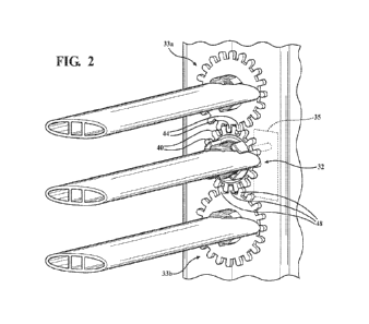
Fig. 2 is a side perspective view of a kinematic end cap with vanes
connected in the open position according to one embodiment of the invention.
2
CA 03232536 2024- 3- 20

WO 2023/064327
PCT/US2022/046368
Fig. 3 is a side perspective view of a kinematic end cap with vanes
connected in the closed position according to one embodiment of the invention.

Fig. 4A is a side elevational view of an end cap with the top vane missing.
Fig. 4B is a side elevational view of the end cap with the top vane missing.
Fig. 5A is a side elevational view of an end cap with the bottom vane
missing.
Fig. 5B is a side elevational view of an end cap with the bottom vane
missing.
Fig. 5C is a side elevational view of an end cap with the bottom vane
missing.
Fig. 6A is an enlarged perspective view of the drive gear with drive vane
connected.
Fig. 6B is an enlarged perspective view of the drive gear with the drive
vane missing.
Fig. 7A is a side perspective view of the formation of the kinematic end
cap.
Fig. 7B is a side perspective view of the formation of the kinematic end
cap.
Fig. 7C is a side perspective view of the formation of the kinematic end
cap.
Fig. 8A is a side elevational view of the kinematic end cap with the drive
gear and driven gears in the forming position.
3
CA 03232536 2024- 3- 20

WO 2023/064327
PCT/US2022/046368
Fig. 8B is a side elevational view of the kinematic end cap with the drive
gear and driven gears in the first rotationally engaged position.
Fig. 8A is a side elevational view of the kinematic end cap with the drive
gear and driven gears in the second rotationally engaged position.
Fig. 9A is a side elevational view of a kinematic linkage assembly in the
open position.
Fig. 9B is a side elevational view of a kinematic linkage assembly in the
closed position.
DETAILED DESCRIPTION OF THE PREFERRED EMBODIMENTS
The following description of the preferred embodiments are merely
exemplary in nature and is in no way intended to limit the invention, its
application, or uses.
Referring now to the figures, with particular reference to Figs. 9A and 9B a
kinematic linkage assembly 10 for an active grille shutter system according to
a
first embodiment of the invention is shown. The kinematic linkage assembly 10
has a frame 12 having formed an aperture 14, wherein the frame 12 is
connectable to a vehicle engine compartment and has a kinematic end cap 16
and an end cap 18 at opposing sides of the aperture 14.
While a single kinematic end cap 16 and end cap 18 are shown with three
vanes it is within the scope of the invention for the kinematic linkage
assembly 10
to have a greater number of kinematic end caps, end caps and vanes depending
on the desired size of the kinematic linkage assembly. In some embodiments the
4
CA 03232536 2024- 3- 20

WO 2023/064327
PCT/US2022/046368
kinematic linkage assembly is modular and the kinematic end cap and end cap
each have connecting features that allows them to be connected together or
stacked to form kinematic linkage assemblies of greater heights. Also, the
vanes
can be formed from extrusion allowing the vanes to have any type of length
depending on the needs of a particular application. An example of the
connecting features between end caps and the extruded vanes is described in
U.S. Patent No. 10,960,754, issued March 30, 2021, titled "MOLD ASSEMBLY
FOR ACTIVE GRILLE SHUTTER SYSTEM" to Lindberg et al, the entire patent is
hereby expressly incorporated by reference.
Referring now to all the figures, the kinematic linkage assembly 10
includes a drive vane 20 and a plurality of driven vanes 22a, 22b, 22c,
wherein
the drive vane 20 has a first end 24 and the plurality of driven vanes 22a,
22b,
22c each have a first end 26a, 26b, 26c each connected to the kinematic end
cap
16. The drive vane 20 has a second end 25 and the plurality of driven vanes
22a, 22b, 22c each have a second end 27a, 27b, 27c, all of which are rotatably
connected respectively to a rotatable holder 29a, 29b, 29c, 29d connected to
the
end cap 18. During operation of the kinematic linkage assembly 10 the drive
vane 20 and the plurality of driven vanes 22a, 22b, 22c are each moveable
between an open position (shown in Fig. 2) and a closed position (shown in
Fig.
3). In the embodiment shown in Figs 2 and 3 there is an open end stop 28 that
driven vane 22a comes into contact with to prevent over rotation of the
kinematic
linkage assembly 10, while the driven vane 22b contacts a closed end stop 30
when the drive vane 20 and driven vanes 22a, 22b, 22c are rotated to the
closed
5
CA 03232536 2024- 3- 20

WO 2023/064327
PCT/US2022/046368
position. When the drive vane 20 and the driven vanes 22a, 22b, 22c are in the

closed position air is prevented from moving through the aperture 14 of the
frame
12. When the drive vane 20 and the driven vanes 22a, 22b, 22c are in the open
position, air moves through the aperture 14 of the frame 12.
The kinematic linkage assembly 10 further includes a drive gear 32
rotatably connected to the kinematic end cap 16. The drive gear 32 has a
portion
34 connected to an actuator 35 by a shaft that extends through the kinematic
end
cap 16 and engages the actuator 35 that is able to rotate the shaft
bidirectionally
depending on the desired position of the drive vane 20 and driven vanes 22a,
22b, 22c. The drive gear 32 further includes a gear portion 38 circumscribing
the
drive portion 34 and includes a plurality of teeth 40 on the outer
circumference of
the gear portion 38. The gear portion 38 has teeth that are in mesh engagement

with teeth 44 formed on a first driven gear 33a and teeth 48 formed on the
second driven gear 33b. The drive portion 34 has at least one pair of vane
engagement fingers 36a, 36b and the gear portion 38 includes at least one pair
of vane engagement tabs 42a, 42b, both of which are configured to connect to
the first end 24 of the drive vane 20.
Referring now to Figs. 2, 3, 6A, 6B, 9 and 10 when the first end 24 of the
drive vane 20 is held by both the vane engagement fingers 36a, 36b and vane
engagement tabs 42a, 42h, the gear portion 38 and the drive portion 34 rotate
together; as rotational force from the actuator 35 is transferred from the
actuator
35 to the driven portion 34 and transferred through the first end 24 of the
drive
vane and onto the gear portion 38. If the first end 24 of the vane 20 is not
held
6
CA 03232536 2024- 3- 20

WO 2023/064327
PCT/US2022/046368
by both the vane engagement fingers 36a, 36b and vane engagement tabs 42a,
42b, such as when the drive vane 20 is broken or missing, the drive portion 34

will rotate independently of the gear portion and there will be no rotational
force
transfer from the drive portion 34 to the gear portion 38, as shown in Fig.
6B.
Subsequently rotational force will not be transferred from the actuator 35 to
the
first driven gear 33a and the second driven gear 33b that are located adjacent

the drive gear 32.
The first driven gear 33a has at least one pair of vane engagement fingers
45a, 45b configured to connect to the first end 26a of the driven vane 26a.
The
plurality of teeth 44 on the outer circumference of the first driven gear 33a
are in
mesh engagement with the plurality of teeth 40 of the gear portion 38 of the
drive
gear 32 so that rotation of the drive gear 32 causes rotation of the first
driven
gear 33a. The second driven gear 33b has at least one pair of vane engagement
fingers 46a, 46b configured to connect to the first end 26b of a second one of
the
plurality of driven vanes 22b. The second driven gear 33b also includes the
plurality of teeth 48 on the outer circumference of the second driven gear 33b

that are in mesh engagement with the plurality of teeth 40 of the drive gear
32 so
that rotation of the drive gear 32 causes rotation of the second driven gear
33b.
Referring also to Figs. 4A and 4B the rotation of the kinematic linkage
assembly 10 when the driven vane 22a (i.e., the upper vane relative to the
driven
vane 20) is broken or missing. The drive vane 20 is rotated in the direction
of the
arrow shown in Fig. 4A and will rotate without the driven vane 22a being
present.
However, an error code will be generated by sensors in the actuator due to
7
CA 03232536 2024- 3- 20

WO 2023/064327
PCT/US2022/046368
differential rotation of the drive gear 32 causing over rotation of the drive
vane
20. Also, an optional safety stop 50 (shown schematically) can be positioned
on
the kinematic assembly or somewhere on the frame 12 to arrest travel of the
drive vane 20 to prevent it from travelling too far and re-closing the
aperture 14.
Referring also to Figs. 5A, 5B and 5C the rotation of the kinematic linkage
assembly 10 when the driven vane 22b (i.e., the lower vane relative to the
driven
vane 20) is broken or missing. The drive vane 20 is rotated in the direction
of the
arrow shown in Fig. 5B and will rotate without the driven vane 22b being
present.
However, an error code will be generated by sensors in the actuator due to
differential rotation of the drive gear 32 causing over rotation of the drive
vane
20. Also, an optional safety stop 52 (shown schematically) can be positioned
on
the kinematic assembly or somewhere on the frame 12 to arrest travel of the
drive vane 20 to prevent it from travelling too far and re-closing the
aperture 14.
Referring now to Figs. 7A, 7B and 7C a method of forming the kinematic
end cap 16 with the drive gear 32 and driven gears 33a, 33b is shown. The
method involves three steps. As shown in Fig. 7A the kinematic end cap 16 is
formed by a first molding step. During a second molding step, shown in Fig. 7B

the driven gears 33a, 33b and gear portion 38 of the drive gear 32 are all
formed.
Lastly during a third molding step, shown in Fig. 7C the drive portion 34 is
separately molded into the aperture of the gear portion 38. This allows for
the
drive portion 34 to be rotatable within the gear portion. Referring now to
Figs.
8A, 8B and 8c formation of the drive gear 32 and driven gears 33a, 33b on the
kinematic end cap 16 is now described in view of the tooling considerations
and
8
CA 03232536 2024- 3- 20

WO 2023/064327
PCT/US2022/046368
requirements. One problem is that the drive gear 32 and driven gears 33a, 33b
must be molded in a way that they will be formed separately so they do not
stick
together, yet in operation they must be able to come into contact. To address
this problem the gear portion 38 of the drive gear 32 has small teeth 52a,
52b,
52c, 52d, driven gear 33a has two small teeth 54a, 54b and driven gear 33b has
two small teeth 56a, 56b. In Fig. 8A the drive gear 32, driven gear 33a and
driven gear 22b are all in the molding position and are formed so that the
small
teeth 52a, 52b of drive gear 32 are adjacent small teeth 54a, 54b of the
driven
gear 33a and will not touch. Likewise small teeth 52c, 52c of drive gear 32
are
adjacent small teeth 56a, 56b of the driven gear 33b are formed and will not
touch. Then as shown in Fig. 8B the drive gear 32 and driven gears 33a, 33b
are
rotated so that the larger teeth are in engagement when the kinematic linkage
assembly 10 is in the fully open position. Likewise in Fig. 8C the drive gear
32
and driven gears 33a, 33b are rotated so that the larger teeth are in
engagement
when the kinematic linkage assembly 10 is in the fully closed position. While
six
small teeth are shown, it is within the scope of the invention for there to be
a
greater or lesser number of small teeth on the drive gear 32 and driven gears
33a, 33b depending on the needs of a particular application, which include the

size, configuration and number of gears.
The description of the invention is merely exemplary in nature and, thus,
variations that do not depart from the gist of the invention are intended to
be
within the scope of the invention. Such variations are not to be regarded as a
departure from the spirit and scope of the
invention.
9
CA 03232536 2024- 3- 20

Representative Drawing
A single figure which represents the drawing illustrating the invention.
Administrative Status

For a clearer understanding of the status of the application/patent presented on this page, the site Disclaimer , as well as the definitions for Patent , Administrative Status , Maintenance Fee  and Payment History  should be consulted.

Administrative Status

Title Date
Forecasted Issue Date Unavailable
(86) PCT Filing Date 2022-10-12
(87) PCT Publication Date 2023-04-20
(85) National Entry 2024-03-20

Abandonment History

There is no abandonment history.

Maintenance Fee

Last Payment of $125.00 was received on 2024-03-20


 Upcoming maintenance fee amounts

Description Date Amount
Next Payment if small entity fee 2025-10-14 $50.00
Next Payment if standard fee 2025-10-14 $125.00

Note : If the full payment has not been received on or before the date indicated, a further fee may be required which may be one of the following

  • the reinstatement fee;
  • the late payment fee; or
  • additional fee to reverse deemed expiry.

Patent fees are adjusted on the 1st of January every year. The amounts above are the current amounts if received by December 31 of the current year.
Please refer to the CIPO Patent Fees web page to see all current fee amounts.

Payment History

Fee Type Anniversary Year Due Date Amount Paid Paid Date
Application Fee $555.00 2024-03-20
Maintenance Fee - Application - New Act 2 2024-10-15 $125.00 2024-03-20
Owners on Record

Note: Records showing the ownership history in alphabetical order.

Current Owners on Record
MAGNA EXTERIORS INC.
Past Owners on Record
None
Past Owners that do not appear in the "Owners on Record" listing will appear in other documentation within the application.
Documents

To view selected files, please enter reCAPTCHA code :


To view images, click a link in the Document Description column. To download the documents, select one or more checkboxes in the first column and then click the "Download Selected in PDF format (Zip Archive)" or the "Download Selected as Single PDF" button.

List of published and non-published patent-specific documents on the CPD .

If you have any difficulty accessing content, you can call the Client Service Centre at 1-866-997-1936 or send them an e-mail at CIPO Client Service Centre.


Document
Description 
Date
(yyyy-mm-dd) 
Number of pages   Size of Image (KB) 
National Entry Request 2024-03-20 2 39
Declaration of Entitlement 2024-03-20 1 19
Declaration 2024-03-20 1 41
Declaration 2024-03-20 1 37
Declaration 2024-03-20 2 97
Patent Cooperation Treaty (PCT) 2024-03-20 1 62
Patent Cooperation Treaty (PCT) 2024-03-20 2 88
Description 2024-03-20 9 310
Claims 2024-03-20 7 186
Drawings 2024-03-20 10 619
International Search Report 2024-03-20 2 52
Correspondence 2024-03-20 2 49
National Entry Request 2024-03-20 9 258
Abstract 2024-03-20 1 14
PCT Correspondence 2024-03-20 4 86
Office Letter 2024-03-21 1 196
Voluntary Amendment 2024-03-20 3 78
Representative Drawing 2024-03-22 1 27
Cover Page 2024-03-22 1 62
Description 2024-03-21 9 316
Amendment 2024-05-09 5 137