Note: Descriptions are shown in the official language in which they were submitted.
CA 03233266 2024-03-25
WO 2023/047364
PCT/IB2022/059049
1
ELECTRIC DYNAMIC POWER CONVERSION SYSTEM
CROSS-REFERENCE TO RELATED APPLICATIONS
[0001] The
present application claims priority to U.S. Provisional Patent Application
Serial No. 63/261,513 filed on September 23, 2021, the content of which is
incorporated
herein by reference in its entirety.
FIELD
[0002] The
present technology relates to an electric dynamic power conversion system
for driving an electric motor, such as an electric motor of an electric
vehicle.
BACKGROUND
[0003] Electromechanical energy converters are known in the art, such as
the electric
motor 106 used in the prior art power train system 100 illustrated in FIG. 1.
Such
electromechanical energy converters are adapted for electrical vehicle (EV)
motors, where
electrical power from a battery 102 is converted and transmitted to an electro-
mechanical
motor 106 by means of an inverter 104.
[0004] A user or software 108 controls the EV by means of software and
hardware
components (not illustrated) in response to different driving conditions. For
instance, when
the user or software 108 varies the speed of an EV from a stopped state to a
moving state
(e.g., via a user interface connected to the power train system 100), the need
in torque for
accelerating and maintaining the vehicle at a given speed varies, and the
inverter 104
controls the rotation per minute (rpm) of the motor 106 accordingly, usually
at a cost of
electrical power efficiency. For example, the user or software 108 may provide
instructions
to the inverter 104, thereby forcing a defined rpm of the motor 106 for a
given torque.
CA 03233266 2024-03-25
WO 2023/047364
PCT/IB2022/059049
2
[0005] The
battery 102 is operable to provide a direct current (DC) to the inverter 104.
For example, the battery 102provided in the form of battery pack composed of a
plurality
of individual cells, the battery being configured to store and provide high
amounts of
energies (e.g., kilowatt-hours) for operating a system, such as an EV. It will
be appreciated
that the battery 102 may be provided in various sizes, shapes and energy
capacity
depending on the application and type of vehicle.
[0006] As
mentioned above, the inverter 104 defines the rpm of the motor 106, by
providing an alternative current (AC) signal of a corresponding frequency
thereto. For
example, to modulate the frequency of the AC signal transmitted to the motor
106, the
inverter 104 includes control and feedback circuitry to transform the input DC
signal
provided by the battery 102 into an AC signal. It will be appreciated that a
motor controller,
an electronic speed controller, an inverter, a motor controller/inverter and a
motor drive
altogether refer to the same element of an EV.
[0007] It
will be appreciated that an electric motor 106, also known as traction motor,
works similarly to other electrical motors used in different applications,
where a rotor
attached to a shaft rotates about an axis concentrical to the center of a
stator, which provides
a rotative motion to the rotor by means of electromagnetic force. In the case
of the electric
motor 106, the speed of the rotor is proportional to the frequency of the AC
signal
circulating in the stator. Thus, the frequency of the AC signal provided by
the motor
controller/inverter 104 is proportional to the rpm of the motor 106.
[0008] The
DC-link (not numbered in FIG. 1) is the electrical connection between the
battery 102 and the inverter 104, and its voltage is the maximum voltage
reference of the
power train system 100. EVs on the market generally share a unique DC-link
voltage,
where the battery 102, the inverter 104 and the maximum phase voltage of the
electric
motor 106 are equal, which simplifies the electrical architecture of the power
train system
100. Some models of EVs have DC-link voltages around the range of 400 volts,
while
incoming EV systems will have DC-link voltages around 800 volts. These high
voltages
will enable to reduce the charging time of the battery 102 because more power
may be
transferred in less time (i.e., less current is needed to transfer the same
power compared to
CA 03233266 2024-03-25
WO 2023/047364
PCT/IB2022/059049
3
a battery with less voltage) and will enable to use smaller electric cables
that are cheaper
and easier to manufacture.
[0009]
However, some issues remain with high-voltage DC links, as driving the
electric
motor 106 with higher voltages at lower speeds and lower torques will increase
power
switching losses in the electric motor 106 and the inverter 104.
SUMMARY
[0010] It
is an object of the present technology to ameliorate at least some of the
inconveniences present in the prior art. One or more embodiments of the
present
technology may provide and/or broaden the scope of approaches to and/or
methods of
achieving the aims and objects of the present technology.
[0011] One
or more embodiments of the present technology have been developed based
on developer's appreciation that while increasing the DC-link voltage in a
power train
system has advantages, it will also increase power losses and decrease the
performance of
the electric motor and inverter, as a non-limiting example via power switching
losses in the
.. inverter, conduction losses, diode losses in the inverter and
copper/winding and iron losses
in the EV motor, and render the power train system at lower speed, lower
torques and/or
lower power usage. It will be appreciated that power train system refers to
the dynamic
drive train when connected to the motor and energy source.
[0012]
Developers of the present technology propose integrating a high frequency DC-
DC power converter in the power train system between the energy source and the
inverter,
which will enable to scale and control the DC-link voltage according to
various motor load
conditions and improve the overall efficiency of the power train system. The
architecture
of such a dynamic drive train system comprising the high frequency DC-DC
converter and
adapted inverter will enable the power train system to benefit from the
advantages of the
high voltage energy sources without suffering from at least some of the
aforementioned
drawbacks.
CA 03233266 2024-03-25
WO 2023/047364
PCT/IB2022/059049
4
[0013] One
or more embodiments of the present technology provide efficiency and
control advantages compared to conventional power trains without DC-DC
converters.
[0014] One
or more embodiments of the present technology enable reducing constraints
on the design of the energy source in the form of a battery, for example by
boosting the DC
voltage when the battery voltage varies due to a reduction of its state of
charge (SoC),
which require electric motors to be designed accordingly (e.g., by scaling the
number of
winding turns in the electric motor to compensate for the reduction of the
battery SoC),
which in turn diminishes the ability of the electric motor to meet the torque
and power
requirements during high-speed operation and in the maximum constant power
curve of
the electric motor. One or more embodiments of the present technology will
enable to
extend the lifespan of the electric motor and its ability to meet torque and
power
requirements during the low battery SoC, while also simplifying the design of
the electric
motor and its cost.
[0015]
Further, one or more embodiments of the present technology will enable
facilitating the design and sizing of the battery and/or electric motor in a
power train of an
EV, while also being adaptable to different types of electric vehicles and/or
applications.
[0016] One
or more embodiments of the present technology provide an architecture for
a dynamic drive train comprising a high-frequency dynamic bi-directional DC-DC
converter and corresponding inverter which function synergistically to
increase real-time
and safety requirements in power train systems and EVs, and where the DC-DC
voltage
and current control loops are synchronized with the torque command and
modulation ratio
to ensure optimal efficiency of the high-frequency DC-DC converter, inverter
and electric
motor and limit noise vibration harshness (NVH) of the power train system. One
or more
embodiments of the present technology provide an architecture that minimizes
dynamic
DC-DC losses, which could cancel the efficiency gains of a variable voltage EV
motor.
[0017] One
or more embodiments of the present technology provide an architecture for
a high frequency DC-DC power converter which may be used with, but not limited
to
Gallium-Nitride (GaN) transistors with corresponding drivers, which enable the
DC-DC
CA 03233266 2024-03-25
WO 2023/047364
PCT/IB2022/059049
power converter to operate at high frequencies and low response time with
power levels
that are optimal for EV power ranges. One or more embodiments of the present
technology
provide at least some of the aforementioned benefits via the architecture of
the high
frequency DC-DC power converter, which includes the selection and placement of
its
5 components, as well as the use of an efficient thermal solution to
optimize their
performance. In one or more embodiments, a corresponding DC-AC inverter may be
used
to provide an output AC signal to the electric motor having the cleanest
waveform possible
without increasing the frequency of the AC signal. In one or more embodiments,
an
electronic control unit in the form of hardware and/or software components is
provided
.. with the high-frequency DC-DC converter and the DC-AC inverter to receive
and control
the required inputs and/or outputs thereof and to optimize their efficiency.
[0018]
Thus, one or more embodiments of the present technology are directed to an
electric dynamic power conversion system.
[0019] In
accordance with a broad aspect of the present technology, there is provided a
dynamic drive train for an electric vehicle comprises: a high frequency direct
current (DC)-
DC power converter electrically connectable to an energy source to receive an
input DC
signal therefrom. The high frequency DC-DC power converter comprises: at least
one
single arm switching power converter, comprises: a half-bridge electrically
connectable to
the energy source, the half-bridge being in thermal contact with a cooling
system comprises
a heat spreader, an inductor electrically connected to the half-bridge, and at
least one
capacitor electrically connected parallel to the inductor, a driver, a DC-DC
controller
operatively connected to the driver. The DC-DC controller is configured to:
receive an
indication of a required power output, receive an indication of the input DC
signal, and
generate, based on the indication of the input DC signal and the indication of
the required
power output, a pulse-width modulated (PWNI) signal, and transmit the PWNI
signal to the
driver. The driver is configured to: receive the PWNI signal from the DC-DC
controller,
generate, based on the PWNI signal, a control signal, and transmit the control
signal to the
half-bridge, the control signal causing the half-bridge to convert the input
DC signal into a
switched DC signal transmitted to the inductor and the at least one capacitor
to obtain an
CA 03233266 2024-03-25
WO 2023/047364
PCT/IB2022/059049
6
output DC signal, the output DC signal having the required power output, and a
DC-
alternative current (AC) inverter electrically connected to the high frequency
DC-DC
power converter to receive the output DC signal therefrom, the DC-AC inverter
being
electrically connectable to an electric motor, the DC-AC inverter being
configured to:
receive an indication of a required inverter output, and convert, based on the
indication of
the required inverter output and the indication the output DC signal, the
output DC signal
into an output AC signal.
[0020] In
one or more embodiments of the dynamic drive train, the indication of the
required inverter output comprises at least one of a required speed and
required torque.
[0021] In one or more embodiments, the indication of the required inverter
output
comprises parameters of a required output AC signal.
[0022] In
one or more embodiments of the dynamic drive train, the dynamic drive train
further comprises: a first DC bus having an input electrically connectable to
the energy
source and being electrically connected to the half-bridge, a second DC bus
electrically
connected to the inductor and the capacitor and to the DC-AC inverter, and an
AC bus
electrically connected to the DC-AC inverter and having an output electrically
connectable
to the electric motor.
[0023] In
one or more embodiments of the dynamic drive train, the dynamic drive train
further comprises a first power sensor electrically connected to the first DC
bus and to the
at least one single arm switching power converter, the first power sensor
being configured
to: measure the input DC signal to obtain the indication of the input DC
signal, and transmit
the indication of the input DC signal to the DC-DC controller.
[0024] In
one or more embodiments of the dynamic drive train, the half-bridge
comprises a first half-bridge, the driver comprises a first driver, the PWIVI
signal comprises
a first PWIVI signal, and the control signal comprises a first control signal,
and the DC-AC
inverter comprises: a DC-AC controller configured to: receive the indication
of the required
inverter output, receive an indication of the output DC signal, and generate,
based on the
indication of the output DC signal and the indication of the required inverter
output, a
CA 03233266 2024-03-25
WO 2023/047364
PCT/IB2022/059049
7
second PWIVI signal, and at least one single arm switching power inverter,
comprises: a
second half-bridge electrically connected to the second DC bus and the AC bus,
and a
second driver electrically connected to the DC-AC controller, the second
driver being
configured to: receive the second PWIVI signal from the DC-AC controller, and
transmit
the second control signal to the second half-bridge, the second control signal
causing the
second half-bridge to convert the output DC signal into the output AC signal.
[0025] In
one or more embodiments of the dynamic drive train, the second half-bridge
is in thermal contact with a second cooling system comprising a second heat-
spreader.
[0026] In
one or more embodiments of the dynamic drive train, the dynamic drive train
further comprises a second power sensor electrically connected to the second
DC bus and
to the AC bus, the second power sensor being configured to: measure the output
DC signal
to obtain the indication of the output DC signal, and transmit the indication
of the output
DC signal to the DC-AC controller for generating the second PWIVI signal.
[0027] In
one or more embodiments of the dynamic drive train, the dynamic drive train
further comprises a third power sensor electrically connected to the second DC
bus between
the first half-bridge and the first inductor, the third power sensor being
configured to:
measure the switched DC signal to obtain an indication of the output switched
DC signal,
and transmit an indication of the output switched DC signal to the DC-DC
controller for
generating the first PWIVI signal.
[0028] In one or more embodiments of the dynamic drive train, the dynamic
drive train
further comprises: a fourth power sensor electrically connected to the AC bus
downstream
the second half-bridge, the third power sensor being configured to: measure
the output AC
signal to obtain an indication of the output AC signal, and transmit an
indication of the
output AC signal to the DC-AC controller for generating the second PWIVI
signal.
[0029] In one or more embodiments of the dynamic drive train, the first
half-bridge
comprises a first high side transistor and a first low side transistor, and
the first driver is
configured to selectively activate one of the first high side transistor and
the first low side
transistor based on the first control signal to obtain the switched DC signal,
and In one or
CA 03233266 2024-03-25
WO 2023/047364
PCT/IB2022/059049
8
more embodiments of the dynamic drive train,: the second half-bridge comprises
a second
high side transistor and a second low side transistor, and the second driver
is configured to
selectively activate one of the second high side transistor and the second low
side transistor
based on the second control signal to obtain the output AC signal.
[0030] In one or more embodiments of the dynamic drive train, the inductor
is
configured to smooth a current waveform of the switched DC signal, and the at
least one
capacitor is configured to smooth a voltage waveform of the switched DC signal
to obtain
the output DC signal.
[0031] In
one or more embodiments of the dynamic drive train, the dynamic drive train
further comprises an electronic control unit operatively connected to the DC-
AC controller,
the electronic control unit being configured to: determine and transmit the
indication of a
required power output to the DC/DC controller, and determine and transmit the
indication
of the required inverter output to the DC-AC controller.
[0032] In
one or more embodiments of the dynamic drive train, at least one of the first
high side transistor and the first low side transistor comprises at least one
of: a bipolar
junction transistor (BJT), a field-effect transistors (FET), a metal-oxide-
semiconductor
field-effect transistor (MOSFET), and an insulated gate bipolar transistors
(IGBT).
[0033] In
one or more embodiments of the dynamic drive train, at least one of the first
high side transistor and the first low side transistor comprises a gallium-
nitride (GaN)
transistor.
[0034] In
one or more embodiments of the dynamic drive train, the first high side
transistor and the first low side transistor are configured in a top-cooled
arrangement with
the heat spreader.
[0035] In
one or more embodiments of the dynamic drive train, the cooling system
further comprises a heat sink fixed onto a surface of the heat spreader.
CA 03233266 2024-03-25
WO 2023/047364
PCT/IB2022/059049
9
[0036] In
one or more embodiments of the dynamic drive train, the heat sink is fixed on
the surface of the heat spreader using a thermal paste.
[0037] In
one or more embodiments of the dynamic drive train, the heat sink is soldered
onto a surface of the heat spreader.
[0038] In one or more embodiments of the dynamic drive train, the first
cooling system
is configured to maintain the first high side transistor and the first low
side transistor at an
operating temperature of about 80 degrees Celsius.
[0039] In
one or more embodiments of the dynamic drive train, the first driver is
configured to operate at a first driver voltage, and the first half-bridge is
configured to
operate at a first bridge voltage, the first driver voltage being at least
twice the first bridge
voltage.
[0040] In
one or more embodiments of the dynamic drive train, the at least one single
arm switching power converter comprises a plurality single arm switching power
converters configured in phase interleave.
[0041] In one or more embodiments of the dynamic drive train, the at least
one single
arm switching power inverter comprises a plurality of single arm switching
power inverter
configured to provide the output AC signal, the output AC signal being a multi-
phase AC
signal.
[0042] In one or more embodiments of the dynamic drive train, a second number
of the
plurality of single arm switching power inverter is proportional to a first
number of the
plurality of single arm switching power converter.
[0043] In
one or more embodiments of the dynamic drive train, a first power range of
operation of the high frequency DC-DC power converter is equal to a second
power range
of operation of the DC-AC inverter.
CA 03233266 2024-03-25
WO 2023/047364
PCT/IB2022/059049
[0044] In one or more embodiments of the dynamic drive train, the high
frequency DC-
DC power converter is configured to operate at frequencies between 500 kHz and
100
MHz.
[0045] In one or more embodiments of the dynamic drive train, high frequency
DC-DC
5 power converter is configured to operate at a power range between 250 W
to 5 kW.
[0046] In
one or more embodiments of the dynamic drive train, the dynamic drive train
further comprises: a first set of capacitors electrically connected to the
first DC bus and to
the half-bridge in the DC-DC power converter, and a second set of capacitors
electrically
connected to the first set of capacitors and the half-bridge, the first set of
capacitors and the
10 second set of capacitors are configured to smooth transients in the
input DC signal.
[0047] In
one or more embodiments of the dynamic drive train, the dynamic drive train
is implemented on at least one printed circuit board (PCB).
[0048] In
accordance with a broad aspect of the present technology, there is provided a
dynamic drive train for an electric vehicle comprising: a control unit, a high
frequency
direct current (DC)-DC power converter electrically connectable to an energy
source to
receive an input DC signal therefrom, the high frequency DC-DC power converter
comprising: a first DC bus, an input of the first DC bus being electrically
connectable to
the energy source, a second DC bus, at least one single arm switching power
converter,
comprising: a half-bridge electrically connected to the first DC bus and the
second DC bus,
the half-bridge being in thermal contact with a cooling system comprising a
heat spreader,
an inductor electrically connected to the half-bridge and the second DC bus,
and at least
one capacitor electrically connected parallel to the inductor and to the
second DC bus, and
a driver, a DC-DC controller operatively connected to the driver and the
control unit, the
DC-DC controller is configured to: receive an indication of a required power
output from
the control unit, receive an indication of the input DC signal, and generate,
based on the
indication of the input DC signal and the indication of the required power
output, a pulse-
width modulated (PWM) signal, and transmit the PWM signal to the driver, and
the driver
is configured to: receive the PWM signal from the DC-DC controller, generate,
based on
CA 03233266 2024-03-25
WO 2023/047364
PCT/IB2022/059049
11
the PWM signal, a control signal, and transmit the control signal to the half-
bridge, the
control signal causing the half-bridge to convert the input DC signal into a
switched DC
signal transmitted to the inductor and the at least one capacitor to obtain an
output DC
signal, the output DC signal having the required power output, and a DC-
alternative current
(AC) inverter electrically connected to the second DC bus to receive the
output DC signal
therefrom, the DC-AC inverter being electrically connectable to an electric
motor, the DC-
AC inverter being configured to: receive an indication of a required inverter
output from
the control unit, and convert, based on the indication of the required
inverter output and the
indication the output DC signal, the output DC signal into an output AC
signal.
[0049] In one or more embodiments of the dynamic drive train, the half-
bridge
comprises a high-side transistor and low-side transistor.
[0050] In one or more embodiments of the dynamic drive train, the high
side transistor
and the low side transistor each comprise a respective gallium-nitride (GaN)
transistor.
[0051] In one or more embodiments of the dynamic drive train, the high
frequency DC-
DC power converter is configured to operate at frequencies between 500 kHz and
100
MHz.
[0052] In one or more embodiments of the dynamic drive train, the high
frequency DC-
DC power converter is configured to operate at a power range between 250 W to
5 kW.
[0053] Terms and Definitions
[0054] In the context of the present specification, the words "first",
"second", "third",
etc. have been used as adjectives only for the purpose of allowing for
distinction between
the nouns that they modify from one another, and not for the purpose of
describing any
particular relationship between those nouns. Thus, for example, it should be
understood
that, the use of the terms "first component" and "third component" is not
intended to imply
any particular order, type, chronology, hierarchy or ranking (for example)
of/between the
components, nor is their use (by itself) intended imply that any "second
component" must
necessarily exist in any given situation. Further, as is discussed herein in
other contexts,
CA 03233266 2024-03-25
WO 2023/047364
PCT/IB2022/059049
12
reference to a "first" element and a "second" element does not preclude the
two elements
from being the same actual real-world element. Thus, for example, in some
instances, a
"first" component and a "second" component may be the same software and/or
hardware,
in other cases they may be different software and/or hardware.
[0055] Implementations of the present technology each have at least one of
the above-
mentioned object and/or aspects, but do not necessarily have all of them. It
should be
understood that some aspects of the present technology that have resulted from
attempting
to attain the above-mentioned object may not satisfy this object and/or may
satisfy other
objects not specifically recited herein.
[0056] Additional and/or alternative features, aspects and advantages of
implementations of the present technology will become apparent from the
following
description, the accompanying drawings and the appended claims.
BRIEF DESCRIPTION OF THE DRAWINGS
[0057] For
a better understanding of the present technology, as well as other aspects
and further features thereof, reference is made to the following description
which is to be
used in conjunction with the accompanying drawings, where:
[0058]
FIG. 1 illustrates a schematic diagram of a prior art power train system for
electric vehicles (EVs).
[0059]
FIG. 2 illustrates a schematic diagram of an energy source, a dynamic drive
train
and a motor interacting with a user and an environment in accordance with one
or more
non-limiting embodiments of the present technology.
[0060]
FIG. 3 illustrates a schematic diagram of the DC-DC power converter of FIG. 2
in accordance with one or more non-limiting embodiments of the present
technology.
[0061]
FIG. 4 illustrates a schematic diagram of the DC-AC inverter of FIG. 2 in
accordance with one or more non-limiting embodiments of the present
technology.
CA 03233266 2024-03-25
WO 2023/047364
PCT/IB2022/059049
13
[0062]
FIG. 5 illustrates a schematic diagram of a single arm switching power
converter
in accordance with one or more non-limiting embodiments of the present
technology.
[0063]
FIG. 6 illustrates a schematic diagram of the half-bridge in the single arm
switching power converter of FIG. 5 in accordance with one or more non-
limiting
embodiments of the present technology.
[0064]
FIG. 7 illustrates a graph of a voltage signal (y-axis) as a function of time
(x-
axis) resulting from activation of the high side transistor and the low side
transistor in the
half bridge of FIG. 6 in accordance with one or more non-limiting embodiments
of the
present technology.
[0065] FIG. 8A, FIG. 8B and FIG. 8C illustrate respectively a side view, a
bottom
perspective view and a top perspective view of the half-bridge and the single
arm switching
power converter of the DC-DC power converter of FIG. 2 implemented on a
printed circuit
board (PCB) in accordance with one or more non-limiting embodiments of the
present
technology.
[0066] FIG. 9A and FIG. 9B illustrate respectively a side view of the
support loop of
the DC-DC power converter on a PCB and a side view of the main decoupling loop
of the
DC-DC power converter on the PCB with the core loop removed in accordance with
one
or more non-limiting embodiments of the present technology.
[0067]
FIG. 10A, FIG. 10B, FIG. 10C and FIG. 10D illustrate respectively a bottom
view and a top view of the DC-DC power converter on the PCB, and a bottom view
and a
top view of a single arm switching power converter removed from the DC-DC
power
converter on the PCB in accordance with one or more non-limiting embodiments
of the
present technology.
[0068]
FIG. 11A, FIG. 11B and FIG. 11C illustrate respectively a side view, a bottom
view and a top view of the single arm switching power converter on a PCB in
accordance
with one or more non-limiting embodiments of the present technology.
CA 03233266 2024-03-25
WO 2023/047364
PCT/IB2022/059049
14
[0069]
FIG. 12 illustrates a perspective view of a heat spreader fixed on a half-
bridge
on a PCB in accordance with one or more non-limiting embodiments of the
present
technology.
[0070]
FIG. 13 illustrates a top view of a DC-DC power converter on a PCB in
accordance with one or more non-limiting embodiments of the present
technology.
[0071]
FIG. 14 illustrates a top view of a dynamic drive train on a PCB, the dynamic
drive train being electrically connected to battery cells and to an electric
motor in
accordance with one or more non-limiting embodiments of the present
technology.
DETAILED DESCRIPTION
[0072] The examples and conditional language recited herein are principally
intended
to aid the reader in understanding the principles of the present technology
and not to limit
its scope to such specifically recited examples and conditions. It will be
appreciated that
those skilled in the art may devise various arrangements which, although not
explicitly
described or shown herein, nonetheless embody the principles of the present
technology
.. and are included within its spirit and scope.
[0073]
Furthermore, as an aid to understanding, the following description may
describe
relatively simplified implementations of the present technology. As persons
skilled in the
art would understand, various implementations of the present technology may be
of a
greater complexity.
[0074] In some cases, what are believed to be helpful examples of
modifications to the
present technology may also be set forth. This is done merely as an aid to
understanding,
and, again, not to define the scope or set forth the bounds of the present
technology. These
modifications are not an exhaustive list, and a person skilled in the art may
make other
modifications while nonetheless remaining within the scope of the present
technology.
Further, where no examples of modifications have been set forth, it should not
be
CA 03233266 2024-03-25
WO 2023/047364
PCT/IB2022/059049
interpreted that no modifications are possible and/or that what is described
is the sole
manner of implementing that element of the present technology.
[0075] Moreover, all statements herein reciting principles, aspects, and
implementations of the present technology, as well as specific examples
thereof, are
5 intended to encompass both structural and functional equivalents thereof,
whether they are
currently known or developed in the future. Thus, for example, it will be
appreciated by
those skilled in the art that any block diagrams herein represent conceptual
views of
illustrative circuitry embodying the principles of the present technology.
Similarly, it will
be appreciated that any flowcharts, flow diagrams, state transition diagrams,
pseudo-code,
10 and the like represent various processes which may be substantially
represented in
computer-readable media and so executed by a computer or processor, whether or
not such
computer or processor is explicitly shown.
[0076]
With these fundamentals in place, we will now consider some non-limiting
examples to illustrate various implementations of aspects of the present
technology.
15 [0077]
One or more embodiments of the present technology are directed towards
adding
design flexibility to power train systems and minimizing compromises in system
performances of electromechanical energy converters in EVs. By placing a high-
frequency
power converter between the energy source (e.g., a battery, fuel cell, etc.)
and the inverter,
one or more embodiments of the present technology enable the inverter and the
motor to
be sized apart from one to another. The high frequency power converter
receives direct
current (DC) input signals from the energy source (e.g., battery, fuel cell,
nuclear energy,
etc.), which may not be constant due to drop in voltages over its discharge,
and provides
the DC input signals to a DC bus with variables properties (i.e., high or low
voltage) to
output DC signals with different voltages. By using a DC-DC controller
configured to
change the DC bus voltage proprieties, the high-frequency DC-DC power
converter
enables generating a wide range of voltages and currents output in order to
match the
demand of the motor drive.
CA 03233266 2024-03-25
WO 2023/047364
PCT/IB2022/059049
16
[0078] One or more embodiments of the high frequency DC-DC power converter of
the
present technology enable reducing the form factor of an electrical power
train system, as
well as having an almost instantaneous response time (i.e., no lag or voltage
drop between
transients) compared to conventional electrical power trains.
[0079] Thus, in one or more embodiments of the present technology, the
energy source
(e.g., battery) may be sized in the power train system according to mechanical
constraints,
without having to comply with the required power input of the motor, and vice
versa, as
would be the case of a system without a power converter. Indeed, power train
sizing
depends on the battery and the motor requirements. It is complex due to the
characteristics
of the systems that both transform energy in a different way (electro
chemically for the
battery, electromotive force for the motor). On top of that, mechanical
constraints are
applied to the sizing characteristics for everything to fit in a very confined
space.
[0080]
These sizing constraints and the different nature of these systems comes with
compromises that must be done, usually to the detriment of performance and/or
range. One
or more embodiments of the present technology provide a high frequency DC-DC
power
converter that acts as a sizing buffer. In one or more embodiments, the energy
source may
be a battery in the form of a battery pack and may be optimized by having a
lower internal
resistance, thus minimizing the heating of the pack by having fewer cells in
series. In one
or more other embodiments, the motor may be designed to operate on higher
voltages
depending on the application to provide more speed, while being coupled to a
low-voltage
battery.
[0081] One
or more embodiments of the present technology provide a bi-directional
dynamic drive train. Generally, a dynamic drive train is used to convert DC
electrical
energy received from a battery into AC energy by providing rotative motion to
a shaft to
.. power a motor (e.g., motor of an EV). One or more embodiments of the
present technology
can be used in reverse as a power conversion unit, where AC electrical energy
from an
outlet may be converted into DC electrical energy and used to charge a power
bank, as a
non-limiting example.
CA 03233266 2024-03-25
WO 2023/047364
PCT/IB2022/059049
17
[0082] Dynamic Drive Train
[0083]
FIG. 2 illustrates a schematic diagram of a power train system 200 interacting
with a user 502 and an environment 504, the power train system 150 being
illustrated in
accordance with one or more non-limiting embodiments of the present
technology.
[0084] The power train system 150 comprises inter alia an energy source
202, a
dynamic drive train 200 and a motor 204 electrically connected to each other.
[0085] The
energy source 202 provides DC electrical power to the dynamic drive train
200, which converts the DC electrical power into AC electrical power and
provides the AC
electrical power to the motor 204. The energy source 202 may be for example a
battery in
the form of a battery pack. As a non-limiting example, the battery pack may be
a lithium-
ion battery pack. Other non-limiting examples of battery packs include lead-
acid battery
packs, nickel-cadmium battery packs, nickel¨metal hydride battery packs, and
sodium
nickel chloride ("zebra") battery packs.
[0086] The
user 502 may operate an electric vehicle comprising the power train system
150, where the power train system 150 receives feedback from the environment
504. It will
be appreciated that the user 502 may provide instructions to the power train
system 200 via
a user interface (not illustrated) in the operatively connected to the power
train system 200.
In the context of the present technology, the user 502 may be a human user or
may be
implemented as a combination of hardware and software, for example as an
autonomous
driving system.
[0087] As
a non-limiting example, in embodiments where the power train system 200
is implemented within an electric vehicle, the user 502 may provide the power
train system
200 with torque requirements such as a given spontaneous acceleration or a
given speed
via the in response to several driving conditions in the environment 504. The
power train
system 150 may acquire parameters from and send feedback to the user 502 via a
first
interface 514 and the receive feedback from the environment via second
interface 516.
CA 03233266 2024-03-25
WO 2023/047364
PCT/IB2022/059049
18
[0088] The
motor 204 is configured to receive the AC electrical energy from the
dynamic drive train 200 and to convert the electrical energy into mechanical
energy to
move the vehicle. The dynamic drive train 200 receives DC electrical energy
from the
energy source via third interface 512, which may be an electrical connection
such as a DC
bus.
[0089] The
dynamic drive train 200 is configured to deliver required power to the motor
204 via fourth interface 518 to control the vehicle comprising the power train
system 150.
[0090] The
dynamic drive train 200 comprises inter alia a DC-DC power converter 300,
a DC-AC inverter 400 and an electronic control unit 500.
[0091] The DC-DC power converter 300 is electrically connected to the
energy source
202, to the DC-AC inverter 400 and to the electronic control unit 500.
[0092] The
DC-DC power converter 300 is configured to inter alia: (i) receive DC
electrical power from the energy source 202; and (ii) provide converted DC
power to the
DC-AC inverter 400. The DC-DC power converter 300 is a high-frequency power
converter configured to inter alia generate a wide range of voltages and DC
signals output
to match the power demand of the DC-AC inverter 400 and according to
instructions
provided by the electronic control unit 500. In other words, the DC-DC power
converter
300 adapts the voltage of the electrical power delivered from the energy
source 202 to
match the voltage of the motor 204 and the power demand via the inverter 400.
[0093] In some alternative embodiments, the DC-DC power converter 300 is
further
configured to distribute electrical power to different components (e.g.,
wipers, lights,
infotainment system, mirror control, set heaters, etc.) (not illustrated) of
the electric vehicle
by converting DC power output by the energy source 202 and providing the
converted DC
power to the components depending on the requirements of the components.
[0094] The DC-DC power converter 300 is configured to operate at high
frequencies
(e.g., between 500 kHz and 100 MHz), which enables reducing its size and
enables having
an almost instantaneous response time by reducing "lag" or voltage drops
between
CA 03233266 2024-03-25
WO 2023/047364
PCT/IB2022/059049
19
transients as well as generating a clean waveform signal that is beneficial
for the longevity
of the connected components. It will be appreciated that since the DC-DC power
converter
300 is part of the motion power flow of the power train system, a short
voltage response
time enables to satisfy the torque response time of the power train system 150
and ensures
the quality of the control of the inverter 400 and the electric motor 204.
Thus, by operating
at high frequencies (e.g., between 500 kHz and 100 MHz), the DC-DC power
converter
300 provides a short response time (e.g., between 10 and 20 microseconds). In
the context
of the present technology, the DC-DC power converter 300 is configured to act
as an energy
converter and as an energy buffer, for example if used in an electric source
hybrid
condition, as will be explained in more detail herein below.
[0095] The
DC-AC inverter 400, also known as inverter, electronic speed controller
(ESC), drive or perfect waveform inverter, is electrically connected to the DC-
DC power
converter 300, to the motor 204 and to the electronic control unit 500.
[0096] The
DC-AC inverter 400 is configured to inter alia: (i) receive the converted
DC signal from the DC-DC power converter 300; (ii) receive control signals
from the
electronic control unit 500; and (iii) generate, based on the control signals
and the
converted DC signal, a multi-phase AC signal to control the motor 204.
[0097] The
DC-AC inverter 400 is configured to convert DC power (i.e. DC electrical
signals) into AC power (i.e., AC electrical signal) with a lower path
resistance so as to
drive the electric motor 204 at a desired reference (i.e., speed or torque).
In the context of
the present technology, the DC-AC inverter 400 is configured to provide a near-
perfect AC
power waveform to the motor 204, which enables improving the efficiency of the
dynamic
drive train 200 and saving energy by inter alia generating less harmonics. It
will be
appreciated that harmonics are a source of power quality problems in
electrical systems
and can result in increased equipment and conductor heating, misfiring in
variable speed
drives, and torque pulsations in motors and generators.
[0098] The
electronic control unit 500, also known as motor control mechanism or
electronic control module, is configured to manage the power transfer from the
energy
CA 03233266 2024-03-25
WO 2023/047364
PCT/IB2022/059049
source 202 to the electric motor 204 by receiving a variety of inputs signals
from different
components and determine output control signals such as torque coordination,
operation
and gearshift strategies, and in some embodiments high-voltage coordination,
charging
control, on board diagnosis, monitoring, thermal management and the like.
5 [0099]
The electronic control unit 500 is electrically connected to each of the DC-
DC
power converter and the DC-AC inverter 400 and forms a control circuit
therewith.
[0100] The
electronic control unit 500 is configured to inter alia receive indications
from sensors in the energy source 202, the DC-DC power converter 300, the DC-
AC
inverter 400, the electric motor 204, as well as indications based on feedback
from the user
10 502,
the environment 504 and other components in an EV (not illustrated) and to
determine
respective control signals indicative of a required output power for each of
the DC-DC
power converter 300 and the DC-AC inverter 400.
[0101] In
one or more embodiments, the electronic control unit 500 is configured to
transmit control signals indicative of the required output power to each of
the DC-DC
15 power converter 300 and the DC-AC inverter 400 according to inter alia the
torque
requirements and power requirements of the electric motor 204, as well as
indications of
measured electrical signals from the DC-DC power converter 300 and the DC-AC
inverter
400.
[0102] The
electronic control unit 500 is configured to balance the reference voltages
20 of the
DC-DC power converter 300 and the DC-AC inverter 400 to optimize the
efficiency
of the dynamic drive train 200. In some embodiments, the electronic control
unit 500 may
also take into account the health of the energy source 202, the DC-DC power
converter 300
and the DC-AC inverter 400 as well as external factors such as the user 502
and/or the
environment 504.
[0103] The electronic control unit 500 comprises a combination of hardware
and
software components and acts as a management and in some embodiments as a
prediction
system for optimizing the operation of the dynamic drive train 200. As a non-
limiting
example, the electronic control unit 500 may comprise micro-controllers, micro-
CA 03233266 2024-03-25
WO 2023/047364
PCT/IB2022/059049
21
processors, random-access memory (RANI), flash memory, and a variety of input
and
output ports and interfaces to interact with EV subsystems and subcomponents.
[0104] The
electronic control unit 500 may include or be connected to electric machine
control system (EMCS), stability control system (SCS), battery management
system
(BMS), driver mode system (DMS), and vehicle control system (VCS).
[0105] In
one or more embodiments, the electronic control unit 500 executes one or
more artificial intelligence (AI) algorithms to optimize the efficiency of the
dynamic drive
train 200, while also taking into account the health of the energy source 202,
the DC-DC
power converter 300 and the DC-AC inverter 400 as well as external factors
such as the
user 502 and/or the environment 504. Thus, in one or more embodiments, the
electronic
control unit 500 enables increasing the amount of optimal operating points,
reduces the
losses in every component, and improves the overall efficiency of the power
train system
150.
[0106] In
one or more embodiments, the electronic control unit 500 receives
information from the user 502 and the environment 504 to analyze and manage
the power
to be converted into motor force, based on a usage profile. The electronic
control unit 500
will not be described in more detail herein.
[0107] In one or more embodiments, the dynamic drive train 200 may be
implemented
on a single printed circuit board (PCB). In one or more other embodiments, the
dynamic
drive train 200 may be implemented on two PCBs, where the DC-DC power
converter 300
may be implemented on a first PCB and the DC-AC inverter 400 may be
implemented on
a second PCB. In one or more embodiments, the electronic control unit 500 may
be
implemented on a single PCB with the dynamic drive train 200, integrated into
one of the
first PCB and second PCB or may be implemented on a separate PCB.
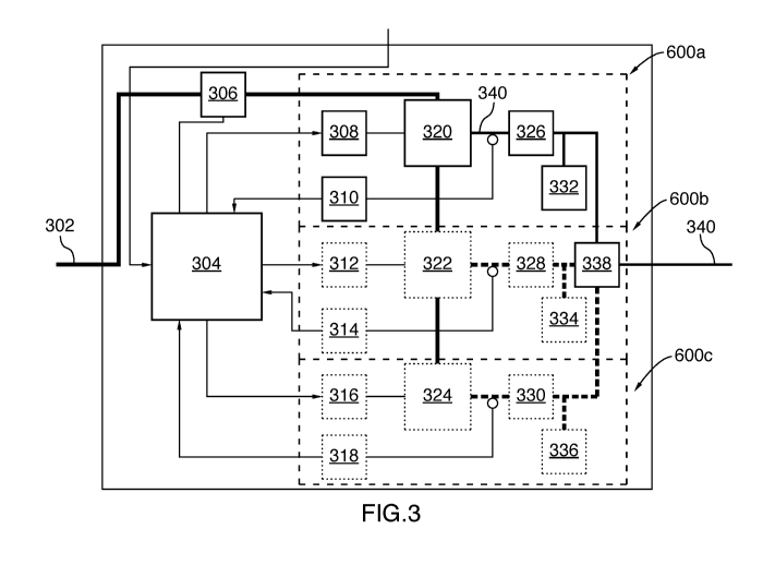
[0108] It will be appreciated by those skilled in the art that the dynamic
drive train 200
may be implemented in different manners without departing from the scope of
the present
technology.
CA 03233266 2024-03-25
WO 2023/047364
PCT/IB2022/059049
22
[0109] DC-DC power converter
[0110] Referring now also to FIG. 3, the DC-DC power converter 300 will now be
described in more detail in accordance with one or more non-limiting
embodiments of the
present technology.
[0111] In the context of the present technology, the DC-DC power converter
300 is used
for adapting the optimal functioning point of efficiency of the DC-AC inverter
400. The
DC-DC power converter 300 acts as an energy converter and to some extent as an
energy
buffer controller if it is used in an electric source hybrid condition.
[0112] The
DC-DC power converter 300 comprises inter alia a source DC bus 302, a
DC-DC controller 304, a first power sensor 306, at least one single arm
switching power
converter 600a, 600b, and 600c, a second DC bus 340, and a second power sensor
338.
[0113]
Each single arm switching power converter 600a, 600b, 600c comprises a
respective driver 308, 312, 316, a respective third power sensor 310, 314,
318, a respective
half-bridge 320, 322, 324, a respective inductor 326, 328, 330 and a
respective capacitor
332, 334, 336.
[0114] The
source DC bus 302 is electrically connected to the first power sensor 306
and to the half-bridge 320, 322, 324 located within the respective single arm
switching
power converter 600a, 600b, 600c. The half-bridge 320, 322, 324, the
respective inductor
326, 328, 330 and the a respective capacitor 332, 334, 336 are electrically
connected to the
second DC bus 340. The second DC bus 340 is electrically connected to the DC-
AC
inverter 400 (best seen in FIG. 4).
[0115] It
will be appreciated the source DC bus 302 and the second DC bus 340 are
electrical conductors configured to transfer DC electrical power from the
energy source
202 to components across the DC-DC power converter 300 and to the DC-AC
inverter 400.
[0116] The DC-DC controller 304, the first power sensor 306, the respective
driver 308,
312, 316, the respective third power sensor 310, 314, 318 and the second power
sensor 338
CA 03233266 2024-03-25
WO 2023/047364
PCT/IB2022/059049
23
are electrically connected together to form a control loop or gate loop for
inter alia
monitoring the electrical power and for controlling the components of the DC-
DC power
converter 300.
[0117] The
DC-DC power converter 300 receives the DC signal from the energy source
202 via the source DC bus 302. The first power sensor 306 is electrically
connected to the
source DC bus 302, and is configured to measure the electrical power flowing
through the
source DC bus 302 and transmit the measurements (i.e., indication of the DC
input signal)
to the DC-DC controller 304. It will be appreciated that the first power
sensor 306 measures
the electrical power flowing through the source DC bus 302 while minimally
affecting it.
For current sensing, the first power sensor 306 may comprise a hall effect
sensor. For
voltage sensing, the first power sensor 306 may comprise a divider bridge. In
one or more
embodiments, the first power sensor 306 may sense a representative value from
0 to 3.3 V
of the input DC signal.
[0118] The
single arm power converter 600a, 600b, 600c is configured to generate the
switched DC signal by using the respective half-bridge 320, 322, 324, where
the switched
DC signal is measured by the respective third power sensor 310, 314, 318, and
where the
current and voltage waveforms of the switched DC signal is smoothed by the
respective
inductor 326, 328, 330 and the respective capacitor 332, 334, 336 to obtain
the converted
DC signal. The driver 308, 312, 316 drives or controls the respective half-
bridge 320, 322,
324 to generate the switched DC signal based on control signals received from
the DC-DC
controller 304.
[0119] The
DC-DC controller 304 is configured to receive control signals indicative of
a required output power of the DC-DC power converter 300. In one or more
embodiments,
the required output power of the DC-DC power converter 300 corresponds to the
required
power input of the DC-AC inverter 400.
[0120] In
one or more embodiments, the control signals indicative of the required output
power of the DC-DC power converter 300 may have been determined based on one
or more
of the input DC signal, the switched DC signal, the output DC signal, the
output AC signal,
CA 03233266 2024-03-25
WO 2023/047364
PCT/IB2022/059049
24
the speed and/or torque requirements of the motor 204, parameters of the
energy source
202, temperature of the components, fault detection in the system, and the
like.
[0121] The
DC-DC controller 304 is configured to generate, based on the control signal
indicative of the required output power, a pulse-width modulated (PWNI) signal
to control
the respective drivers 308, 312, 316 such that a DC signal with the required
power is
generated at the output of second DC bus 340 of the DC-DC converter 300.
[0122] In
one or more embodiments, the DC-DC controller 304 is electrically connected
to the electronic control unit 500 to receive and transmit indications and
control signals.
Additionally or alternatively, the DC-DC controller 304 may be electrically
connected to
the DC-AC inverter 400 to receive the indications and control signals.
[0123] In
one or more embodiments, the DC-DC controller 304 is configured to
determine the PWNI signal based on at least the indication of the input DC
signal and the
indication of the required power input of the DC-AC inverter 400.
[0124] In
some embodiments, the DC-DC controller 304 is further configured to receive
at least one of an indication of the measured input DC signal from the first
power sensor
306 and an indication of the measured output switched DC signal from the third
power
sensor 310, 314, 318 and to generate, further based on the at least one
indication of the
received measured input DC signal and the indication of the measured output
switched DC
signal, a pulse-width modulated (PWNI) signal, which is then transmitted to
the driver 308,
312, 316.
[0125]
Each driver 308, 312, 316 is configured to receive the PWNI signal from the DC-
DC controller 304 and generate and transmit, based on the PWNI signal, a
control signal
for selectively activating a high side and low side transistor gate of the
respective half-
bridges 320, 322, 324 to output switched DC signal.
[0126] The half-bridge 320, 322, 324 is configured to generate, by
receiving the input
DC signal and based on the control signal provided by the respective driver
308, 312, 316,
a switched DC signal. The switched DC signal output from the half-bridge 320,
322, 324
CA 03233266 2024-03-25
WO 2023/047364
PCT/IB2022/059049
is thereafter transmitted to respective inductor 326, 328, 330 and to a ground
(not
illustrated).
[0127] It
will be appreciated that the half-bridge 320, 322, 324 serves as a mean to
vary
the voltage of the input DC signal to generate a switched DC signal by
charging and
5 discharging the inductors 326, 328, 330 (or motor coil if it is the load)
at high frequencies.
The switched DC signal output from the half-bridge 320, 322, 324 is
transmitted to a
respective inductor 326, 328, 330. The inductor 326, 328, 330 is configured to
smooth the
current waveform in the switched DC signal and store the electrical energy as
magnetic
energy.
10 [0128]
The smoothed switched DC signal output by the inductor 326, 328, 330 is
transmitted to a respective capacitor 332, 334, 336 and then to the DC bus
340. In one or
more embodiments, the capacitor 332, 334, 336 is configured to smooth the
voltage
waveform of the switched DC signal by storing the electrical energy in an
electric field to
obtain the output DC signal, which is then transmitted to the DC bus 340.
While there is
15 only one respective capacitor 332, 334, 336 it should be understood that
there may be a
plurality of capacitors in each half-bridge 320, 322, 324.
[0129] In
some embodiments, the switched DC signal transmitted by each of the half-
bridge 320, 322, 324 to the respective inductor 326, 328, 330 is measured by a
respective
third power sensor 310, 314, 318 and an indication of the resulting
measurement is
20 transmitted to the DC-DC controller 304. Each third power sensor 310,
314, 318 is
configured to measure a state of saturation of the respective inductor 326,
328, 330 to
provide feedback to the control loop comprising the DC-DC controller 304. The
DC-DC
controller 304 may vary the PWNI signal provided to the drivers 308, 312, 316
according
to the indication received from the third power sensor 310, 314, 318.
25 [0130]
The DC bus 340 transmits the converted or output DC signal from the DC-DC
power converter 300 to the DC-AC inverter 400.
[0131] In one or more embodiments, the converted DC signal output from the DC-
DC
power converter 300 is measured by the second power sensor 338. The second
power
CA 03233266 2024-03-25
WO 2023/047364
PCT/IB2022/059049
26
sensor 338 is connected to the DC bus 340 between the DC-DC power converter
300 and
the DC-AC controller 402. In some embodiments, the second power sensor 338 is
configured to transmit an indication of the measured converted DC signal to at
least one of
the DC-DC controller 304, the DC-AC controller 402 and the electronic control
unit 500
as feedback for the control loop. In one or more embodiments, the second power
sensor
338 is configured sense a representative value from 0 to 3.3 V of the input DC
signal.
[0132] It
should be understood that the number of single arm switching power
converters 600a, 600b, 600c may vary from embodiment to embodiment and
depending on
the application, and the number of single arm switching power converters 600a,
600b, 600c
illustrated in FIG. 3 is exemplary only.
[0133] In
one or more other embodiments, the number of half-bridges 320, 322, and
324 may vary depending on the application.
[0134] In
one or more alternative embodiments of the present technology, the number
of half-bridge 320, 322, 324 may be doubled at each location so as to form
full bridges
(i.e., each half-bridge 320, 322, 324 is replaced by a full bridge comprising
two half-
bridges). It will be appreciated that in such instances, the electrical
connections and
components within the respective single arm switching power converters 600a,
600b, 600c
may be positioned differently. It will be further appreciated that the full
bridges may be
interleaved.
[0135] In one or more embodiments, the DC-DC power converter 300 is
implemented
as a bidirectional full bridge buck boost DC-DC power converter based on
Gallium Nitride
(GaN) transistors. In the context of the present technology, GaN transistors
are used in the
single arm switching power converters 600a, 600b, 600c of the DC-DC power
converter
300 to switch power quickly while maintaining a very high frequency of
operation. Due to
their low "on resistance" substrate and their high band gap, it will be
appreciated that GaN
transistors can reach higher frequencies more efficiently.
[0136] In one or more embodiments, the DC-DC power converter 300 is configured
to
operate at a lower power range, such as between 250 W to 5 kW in combination
with the
CA 03233266 2024-03-25
WO 2023/047364
PCT/IB2022/059049
27
DC-AC inverter 400 operating at the same power range. It will be appreciated
that the
present technology is not limited to GaN transistors, and different types of
transistors may
be used as long as such transistors can operate at very high frequencies. For
instance, in
one or more alternative embodiment, the transistors may include one or more
of: bipolar
junction transistors (BJTs), field-effect transistors (FETs), metal-oxide-
semiconductor
field-effect transistors (MOSFETs), insulated gate bipolar transistors (IGBTs)
and the like.
[0137] In
one or more embodiments, a given driver 308, 312, 316 may be implemented
as a LMG1210 available from Texas Instruments (TI) (Texas Instruments
Incorporated,
Dallas, Texas, U.S.), which is a 200-V half-bridge MOSFET and Gallium Nitride
Field
Effect Transistor (GaN FET) operating at frequencies up to 50 MHz, which does
not have
a perfect waveform signal but enables driving high frequencies, which is
suitable for high
frequency power conversion applications and enables reducing the size of the
components
of the dynamic drive train 200.
[0138] DC-AC Inverter
[0139] With reference to FIG. 4, the DC-AC inverter 400 will now be
described in more
detail in accordance with one or more non-limiting embodiments of the present
technology.
[0140] In
the context of the present technology, the DC-AC inverter 400 is not used to
increase frequency of the signal as it has negligible effects on the
efficiency and/or
formfactor of the motor 106. Developers of the present technology have
appreciated that
having the cleanest possible output waveform, defined by a near perfect square
wave that
has the sharpest edge and that contains the least harmonics possible, enables
minimizing
residual signals generated by switching, which can be considered as wasted
energy as well
as hazardous for the motor 204 itself.
[0141]
Overshoots and sharp transients in the motor are known to be destructive to
the
motor in extensive usage, due to overshoots in voltages breaking the
dielectric barrier over
time. In the long term, the dielectric barrier fragilize itself proportionally
to the amount of
overshoots it takes. After the dielectric barrier fails, a short circuit
between the rest of the
winding is created, shorting the whole motor, and damaging it. The reduction
of transients
CA 03233266 2024-03-25
WO 2023/047364
PCT/IB2022/059049
28
also comes with a much more precise control, and better efficiency, as
transients are losses
of energy which do not provide wanted torque on the mechanical shaft. Thus, by
generating
cleaner waveforms, the DC-AC inverter 400 enables improving the performance
and
longevity of the motor 204.
[0142] The DC-AC inverter 400 comprises the DC bus 340, a single arm
switching
power inverter 403a, 403b 403c, a DC-AC controller 402, and a motor bus 422.
[0143] The
respective second single arm switching power inverter 403a, 403b, 403c is
similar to the respective single arm switching power converter 600a, 600b,
600c, but
without the capacitor 332, 334, 336 and the inductor 326, 328, 330. Each
second single
arm switching power inverter 403a, 403b, 403c comprises a respective second
driver 404,
408, 412, a respective second half-bridge 416, 418, 420 and a respective
fourth power
sensor 406, 410, 414.
[0144] The
respective second single arm switching power inverter 403a, 403b, 403c is
configured to generate the output AC signal via the second half-bridge 416,
418, 420 by
converting the output DC signal. The output AC signal is measured by the
respective fourth
power sensor 406, 410, 414.
[0145] The
DC bus 340, the second half-bridge 416, 418, 420 and the motor bus 422
form a power loop for transmission of electrical power from the DC-DC power
converter
400 to the motor 204.
[0146] The DC-AC controller 402, the respective second driver 404, 408, 412
and the
respective fourth power sensor 406, 410, 414 form a control loop. It will be
appreciated
that that the DC-AC controller 402 is also electrically connected to the DC-DC
controller
304, the second power sensor 338, and the electronic control unit 500 to form
the control
loop.
[0147] The respective second driver 404, 408, 412 control or drive the
respective second
half-bridge 416, 418, 420 to generate the output AC signal by converting the
output DC
signal based on control signals received from the DC-AC controller 402.
CA 03233266 2024-03-25
WO 2023/047364
PCT/IB2022/059049
29
[0148] The
DC-AC controller 402 is configured to receive signals comprising
indications of a required output of the DC-AC inverter 400. In one or more
embodiments,
the indication of the required inverter output comprises a required torque and
required
speed for driving the motor 204.s
[0149] In one or more embodiments, the signals indicative of the required
output of the
DC-AC inverter 400 may be determined based on one or more of the input DC
signal, the
switched DC signal, the output DC signal, the output AC signal, the speed
and/or torque
requirements of the motor 204, temperature of the components, fault detection
in the
system and the like.
[0150] In one or more embodiments, the DC-AC controller 402 receives the
signal
indicative of the required inverter output from the electronic control unit
500. In one or
more other embodiments, the DC-AC controller 402 may determine the required
output
based on information received from at least the motor 204.
[0151] The
DC-AC controller 402 is configured to generate, based on the indication of
the output DC signal and the signal indicative of the required inverter
output, a pulse-width
modulated (PWNI) signal to control the respective drivers 404, 408, 412 such
that an AC
signal with the required parameters is generated at the output of motor bus
422 and
transmitted to the electric motor 204.
[0152] In
one or more embodiments, the DC-AC controller 402 is configured to receive
an indication of a reference speed and a reference torque for the motor 204
from the
electronic control unit 500, and to receive an indication of the measured
converted DC
signal based on the converted DC signal received from the DC-DC power
converter 300.
[0153] The
DC-AC controller 402 is configured to: determine, based on the signal
indicative of the required inverter output comprising at least one of the
reference speed and
the reference torque and the indication of the converted DC signal, the second
PWNI signal
indicative of the converted AC signal. The DC-AC controller 402 is configured
to transmit
the second PWNI signal to the second drivers 404, 408, 412, which cause the
second half-
CA 03233266 2024-03-25
WO 2023/047364
PCT/IB2022/059049
bridge 416, 418, 420 to generate and output the converted AC signal using the
output DC
signal.
[0154] In
one or more embodiments, the second driver 404, 408,412 is configured to
operate at high voltages, which improves the overall system efficiency, as
each of the
5 second half-bridges 416, 418, 420 requires high voltages to open and
close its gates. Thus,
by using the second driver 404, 408, 412 designed and configured for high
voltage uses,
the 100V GaN transistors can be charged and discharged more rapidly than
standard drivers
would, thus allowing sharper rise and fall time of the transistors and
providing sharper
waveforms in the output AC signal to the electric motor 204.
10 [0155]
In one or more embodiments, the DC-AC controller 402 is further configured
to
receive an indication of the measured converted AC signal from the fourth
power sensors
406, 410, 414, and to generate, based on indication of the measured converted
AC signal,
the indication of the measured output DC signal and the indication of the
required inverter
output, a second PWNI signal for transmission to the second driver 404, 408,
412. Each
15 second driver 404, 408, 412 is configured to receive the second PWNI
signal from the DC-
AC controller 402, and to transmit, based on the second PWNI signal, a second
control
signal to the second half-bridge 416, 418, 420. The second half-bridge 416,
418, 420 is
configured to receive the converted DC signal from the second bus 340, receive
the second
control signal from the second drivers 404, 408, 412, and to convert the
output DC signal
20 into a converted AC signal based on the second control signal.
[0156] The
second half-bridges 416, 418, 420 are configured to convert the DC signal
into a converted AC signal, and transmit the converted AC signal to the motor
204 via the
motor bus 422 electrically connected to the motor 204. It will be appreciated
that the AC
signal output by the second half-bridges 416, 418, 420 is measured by the
fourth power
25 sensors 406, 410, 414 respectively, which provide the measurements to at
least the DC-AC
controller 402 as feedback in the control loop.
[0157] In
one or more embodiments, the fourth power sensor 406, 410, 414 is in the
form of hall effect sensor that sense the variation of the phase current that
is fed to the
CA 03233266 2024-03-25
WO 2023/047364
PCT/IB2022/059049
31
motor bus 422. In other embodiments, the fourth power sensor 406, 410, 414 is
a shunt
sensors which sense the back electromotive force (Back-EMF). In this
configuration, the
shunt sensors measure the phase that is not powered by the DC-AC inverter 400,
such as
only two phases out of three that are powered by cycle.
[0158] In one or more embodiments, a given second driver 404, 408, 412 may
be
implemented as NCP51820 available from Onsemi (ON Semiconductor Corporation,
Phoenix, Arizona, US), which is a 650 V half bridge gate driver for GaN power
switches,
which has a lower frequency operating range and which is conventionally used
for 650V
GaN transistors (instead of 100 V GaN transistors as in the present case) but
which enables
generating a waveform of higher quality compared to a given driver 308, 312,
316 of the
DC-DC power converter 300. The DC-AC inverter 400 operates at the same power
range
as the DC-DC power converter 300.
[0159] In some embodiments, the DC-AC inverter 400 is operable to generate an
AC
signal with a frequency which may be between 500 kHz to 100 MHz. In other
embodiments, the frequency of the output AC signal may be comprised between
500 kHz
to 10 MHz.
[0160] It should be noted that in one or more alternative embodiments of
the present
technology, the DC-AC inverter 400 may operate in the same frequency range as
the DC-
DC power converter 300, such as with coreless electric motors for example.
[0161] Sin21e arm switchin2 power converter
[0162] Referring also to FIG. 5, the single arm switching power converter
600a which
may be one of the single arm switching power converter 600a, 600b, 600c
included in the
DC-DC power converter 300 will now be described in more detail in accordance
with one
or more non-limiting embodiments of the present technology.
[0163] The single arm switching power converter 600 is also known as a core
cell or a
commutation system.
CA 03233266 2024-03-25
WO 2023/047364
PCT/IB2022/059049
32
[0164] The
single arm switching power converter 600 comprises inter alia the driver
308, the third power sensor 310, a half-bridge 320, an inductor 326, and a
capacitor 332.
[0165] The
driver 602 is electrically connected to the half-bridge 320, the half-bridge
320 being electrically connected to the source DC bus 302 and to the inductor
326.
[0166] The half-bridge 320 is configured to receive the DC signal from the
source DC
bus 302 and to transmit a switched DC signal to the inductor 326. The inductor
326 is
connected in parallel with the capacitor 332 and to the DC bus 340 and is
configured to
output a smoothed switched DC signal. The switched DC signal provided to the
inductor
326 from the half-bridge 320 is measured by the third power sensor 310, and
the
measurement is transmitted to the DC-DC controller 304. It will thus be
understood that
the foregoing embodiment of the single arm switching power converter 600a is
included in
the DC-DC power converter 300 and can be connected in parallel with at least
one other of
the single arm switching power converter (e.g., 600b, 600c) to stabilize the
output DC
signal.
[0167] In one or more embodiments, the inductor 326 is configured to
receive the
switched DC signal and to generate a smoothed switched DC signal, and the
capacitor 332
is configured to receive the smoothed switched DC signal and to generate the
converted
DC signal. In one or more embodiments, the inductor 326 is connected in
parallel with the
capacitor 332.
[0168] In some embodiments, combining multiple single arm switching power
converters such as single arm switching power converters 600a, 600b, 600c
enable
improving the system characteristics. For instance, connecting a plurality of
single arm
switching power converters 600a, 600b, and 600c in series enables outputting
greater
output voltages than conventional drive trains. Additionally, interleaving a
plurality of
single arm switching power converters 600a, 600b, and 600c connected in
parallel enables
outputting a wider power range than in conventional drive trains, thus
ensuring stability
and efficiency in the delivered electrical power to the electric motor 204,
depending on the
requirements in speed and torque. Having a plurality of interleaved single arm
switching
CA 03233266 2024-03-25
WO 2023/047364
PCT/IB2022/059049
33
power converters 600a, 600b, and 600c connected in parallel also enables
having a better
control of the output electrical power, thus reducing the required filtering
of the output DC
signal, and enables maintaining a functional system in the case where one of
the single arm
switching power converters 600a, 600b, and 600c stops functioning.
[0169] With reference to FIG. 6, components of the half-bridge 606 are
illustrated in
accordance with one or more non-limiting embodiments of the present
technology.
[0170] The
half-bridge 606 may replace one or more of the half bridges 320, 322, 324
of the DC-DC power converter 300.
[0171] The
half-bridge 606 comprises inter alia a first set of capacitors 670, a second
set of capacitors 680, a high side transistor 612 and a low side transistor
614 and a cooling
system 700.
[0172] The
high side transistor 612 and the low side transistor 614 are both in thermal
contact with a thermal heatsink in the cooling system 700, which serves as a
thermal
regulator for the transistors 612, 614.
[0173] The half-bridge 320 comprises the first set of capacitors 670 and
the second set
of capacitors 680, which are configured to smooth the transients in the DC
signal, as will
be explained below. Further, it will be appreciated that in the foregoing
embodiment, two
capacitors 620, 624 are connected to the DC bus 601 to improve smoothing of
the switched
DC signal and to increase the amount of electrical energy stored in the
electric field.
[0174] In one or more embodiments, the half-bridge 606 may be replaced by a
full-
bridge (i.e., two half-bridges) to enable buck and boost switching.
[0175] The
high side transistor 612 is electrically connected to the high side of the
source DC bus 302 and to the inductor 326. The high side transistor 612 is
configured to
receive the input DC signal from the source DC bus 302 to generate a switched
DC signal
to the inductor 326 when activated by the driver 308. The high side transistor
612 is
configured to transmit the switched DC signal to the inductor 326 in response
to the control
CA 03233266 2024-03-25
WO 2023/047364
PCT/IB2022/059049
34
signal from the driver 308. The high side transistor 612 is thus configured to
charge the
inductor 326 or the motor coil.
[0176] The
low side transistor 614 is connected to a ground (not illustrated) and to the
inductor 608. The low side transistor 614 is configured is configured to
receive the input
DC signal from the source DC bus 302 and to stop providing the switched DC
signal to the
inductor 608 when activated by the driver 308. The low side transistor 614 is
configured to
stop transmission of the switched DC signal to the inductor 608 in response to
the control
signal received from the driver 308. The low side transistor 614 is thus
configured to
discharge the inductor 326 or the motor coil.
[0177] During operation of the half-bridge 320, only one of the high side
transistor 612
and the low side transistor 614 is activated at a time to avoid damaging the
system by
shorting the provided DC signal to the ground.
[0178]
Referring also to FIG. 7, there is illustrated a graph 750 showing a typical
signal
resulting from subsequent activations of the high side transistor 612 and the
low side
.. transistor 614, the signal being provided in the form of a voltage (y-axis)
as a function of
time (x-axis). When the high side transistor 612 is activated, it takes a
certain amount of
time, referred to as rise time, to reach a first predefined percentage of the
target value, e.g.,
80% of the targeted value. In some embodiments, due to system imperfections,
the voltage
may overshoot and undershoot the target of 100% before stabilizing over time,
which may
cause damages to the system and lower the overall efficiency. Similarly, when
the low side
transistor 614 is activated, it takes a certain amount of time, referred to as
fall time, to reach
a second predefined percentage of the target value, e.g., 20% of the targeted
value. In some
embodiments, due to system imperfections, the voltage may overshoot and/or
undershoot
the target of 0% before stabilizing over time, which may lower the overall
efficiency. It
will be understood that the aforementioned characteristic parameters of the
signal may be
influenced by system components, such as the circuitry, the transistor, the
capacitors, the
inductors, and the like.
CA 03233266 2024-03-25
WO 2023/047364
PCT/IB2022/059049
[0179] In
some embodiments, the DC-AC inverter 400 also comprises the single arm
switching power converter 600, which are connected to the DC-AC controller 402
and
convert a DC signal into an AC signal.
[0180] In
one or more embodiments, a multi-phase signal can be generated and
5
transmitted to the motor 204 by using more than one single arm switching power
inverter
(e.g., second single arm switching power inverter 403a, 403b, 403c of FIG. 4)
in the DC-
AC inverter 400.
[0181]
FIGS. 8 to 11 illustrate various components of the DC-DC power converter
implemented on printed circuit boards (PCBs).
10 [0182]
FIGS. 8A, 8B and 8C illustrate respectively a side view, a bottom
perspective
view and a top perspective view of a half-bridge and a single arm switching
power
converter of a DC-DC power converter implemented on a PCB in accordance with
one or
more non-limiting embodiments of the present technology.
[0183]
FIGS. 9A and 9B illustrate respectively a bottom view and a top view of the DC-
15 DC
power converter with the single arm switching power converter removed in
accordance
with one or more non-limiting embodiments of the present technology.
[0184]
FIGS. 10A, 10B, 10C and 10D illustrate respectively a bottom view and a top
view of the DC-DC power converter 300 with the single arm switching power
converter
600 removed, and a bottom view and a top view of the single arm switching
power
20
converter 600 removed from the DC-DC power converter 300 in accordance with
one or
more non-limiting embodiments of the present technology.
[0185] Power Loops
[0186]
FIGS. 9A and 9B illustrate a gate loop 802 and a power loop 804 on a dynamic
drive train in accordance with one or more non-limiting embodiments of the
present
25 technology.
CA 03233266 2024-03-25
WO 2023/047364
PCT/IB2022/059049
36
[0187] It
will be appreciated that electrical power loops are critical in the overall
performance of a dynamic drive train such as the dynamic drive train 200.
Having longer
electrical power loops typically results in more parasitic elements in the
signal and
drastically amplifies the noise created when the switching occurs in the
transistors. Every
millimeter of trace added in the electrical loops may cause more overshoots
and
undershoots in the signal which may damage the transistors and reduce the
overall
efficiency of the dynamic drive train 200.
[0188]
Capacitors of various sizes may be used to filter parasitic noise on various
frequencies. Typically, capacitors with high capacitance tend to have a larger
form-factor,
thus being more difficult to fit next to the single arm switching power
converters. The use
of such large form-factor capacitors may be omitted to reduce the lengths of
loops, at a cost
of not filtering the noise of low frequencies, which limits the amount of
usable power.
[0189]
Further, thermal cooling is often prioritized and thermal cooling components
are
placed next to the single arm switching power converters, which increases the
length of the
loops. Typically, heatsinks are fixed on one of the lateral surfaces of the
transistors using
thermal paste. It should be understood that the transistors must be maintained
below a
critical temperature to avoid being damaged or destroyed.
[0190] The
gate loop 802 comprises a circuitry that connects the drivers 308, 312, 316,
second drivers 404, 408, 412, the DC-DC controller 304, the DC-AC controller
402 and
the single arm switching power converters 600a, 600b, 600c, the second single
arm
switching power inverter 403a, 403b, 403c and provides electrical current for
activating
the transistors in the half-bridges 320, 322, 324, and the second half-bridges
416, 418, 420.
[0191] The
power loop 804 comprises electrical circuitry that connects the energy
source 202, the DC-DC power converter 300, the DC-AC inverter 400 and the
motor 106.
In one or more embodiments, the electrical circuity comprises a source DC bus,
a second
DC bus and a motor AC bus. It should be understood that the current
circulating in the
power loop 804 is usually greater than the current circulating in the gate
loop 802.
CA 03233266 2024-03-25
WO 2023/047364
PCT/IB2022/059049
37
[0192]
Still referring to FIGS. 9A and 9B, the gate loop 802 overlaps with the power
loop 804. It will be appreciated that overlapping the loops 802, 804 requires
the use of top
cooled transistors, which may be less efficient in extracting heat than bottom
cooled
transistors. However, in the context of the present technology, due to the
circuit layout, top
cooled transistors are used and enable minimizing the length of the loops 802,
804, which
is beneficial for operation of the dynamic drive train 200.
[0193]
Further, overlapping the loops 802, 804 enables using multiple ranges of
filtering capacitors and bulkier capacitors compared to the dispositions known
in the art,
thereby allowing the dynamic drive train 200 to operate at high frequencies
and at high
powers.
[0194] The
power loop 804 comprises a main decoupling loop 860 and a support loop
880. The main decoupling loop 860 comprises the first set of capacitors 870
(also seen in
FIG. 8A, and FIGS. 11A to 11B) which corresponds to the first set of
capacitors 670 (FIG.
5) and the support loop 880 comprises the second set of capacitors 890 (also
seen in FIG.
FIG. 8A), which correspond to the second set of capacitors 680 (FIG. 5).
[0195] The
main decoupling loop 860 provides straight to the transistors (e.g., GaNs)
in the half-bridges (not numbered) in the single arm switching power converter
600, the
charges required at instant t=0+, meaning that when the transistors close, the
charges are
transmitted from the first set of capacitors 870 to smoothen the transients.
These are the
lowest resistance paths possible, as the capacitors 870 themselves are very
low equivalent
series resistance (ESR) / equivalent series inductance (ESL) (e.g., MultiLayer
Ceramic
Capacitors (MLCC)). Because of these characteristics, the set of capacitors
870 have a low
capacity to store energy, and due to the high power going through the circuit,
the first set
of capacitors 870 may not be as useful in their action when discharged. A
second
decoupling loop 880 or support loop 880 is present to counteract the effect of
the first set
of capacitors 870 in the main decoupling loop 860. Further away from the
design, but still
very close in comparison to DC bus capacitors with larger form factors, the
second set of
capacitors 890 in the support loop 880 acts as a secondary reservoir to
support the main
decoupling loop 860, and still provides enough charges to the main decoupling
loop 860
CA 03233266 2024-03-25
WO 2023/047364
PCT/IB2022/059049
38
as well as providing direct charges passing through the closed transistors.
Using this
configuration comprising the main decoupling loop 860 and the support loop
880, the
present technology can reach the full harmonic spectrum of the transients to
provide an
optimal waveform.
[0196] Thermal Solution
[0197] FIG. 12 illustrates a perspective view of a heat spreader fixed on
the half-bridge
of FIG. 6 in accordance with one or more non-limiting embodiments of the
present
technology.
[0198] The heat spreader 900 part of the cooling system 700 (FIG. 7) is
configured to
transfer heat generated by the electronic components in the half-bridge where
it is
dissipated away from the electronic components to enable regulation of
temperature and
ensure optimal functioning of the components.
[0199] High voltage transistors such as GaN transistors typically
generate high amounts
of heat concentrated in small areas, and it is usually difficult to extract
heat due to a fuzzy
bonding between the transistors and the heatsink. Using the heat spreader 900
enables to
efficiently extract heat from high voltage transistors and to avoid damages
caused by high
temperatures.
[0200] The heat spreader 900 is fixed, using a thermal paste, onto the
top surface of the
transistors (e.g. high side transistor 612 and low side transistor 614). The
heat spreader 900
is in contact with the high side transistor 612 and the low side transistor
614 (seen in FIG.
6). In some embodiments, the thermal solution further comprises a heatsink
(not
illustrated), which is typically fixed on the heat spreader 900 using thermal
paste. The
heatsink typically consists of a plate having a plurality of parallel fins
extending from its
surface.
[0201] When the transistors operate, heat is generated, the heat spreader
will conduct
the generated heat in ambient air, thereby maintaining the transistors at an
operable
temperature range. In some embodiments, the operable temperature range is
between 70 C
CA 03233266 2024-03-25
WO 2023/047364
PCT/IB2022/059049
39
to 90 C. In one embodiment, the maximum working temperature of the transistors
is
135 C. In some embodiments, the heatsink and the heat spreader 900 are at
least composed
of one of aluminium and of copper. It will be appreciated that the heatsink
and heat spreader
may include composite materials.
[0202] FIG. 13 illustrates a top view of a power converter in accordance
with one or
more non-limiting embodiments of the present technology.
[0203]
FIG. 14 illustrates a top view of a dynamic drive train 1200 comprising
battery
cells 1202, a DC-DC power converter 1204, a DC-AC inverter 1206 and a motor
1208 in
accordance with one or more non-limiting embodiments of the present
technology.
[0204] One or more embodiments of the present technology enable adding
design
flexibility and minimizing compromises in system performances of power train
systems in
EVs. By placing a high-frequency DC-DC power converter in between an inverter
and a
battery, one or more embodiments the present technology enable the motor
controller/inverter and the motor to be sized apart from one to another. By
having as an
input a controller configured to change the DC bus proprieties, the high-
frequency DC-DC
power converter enables generating a wide range of voltages and currents
output in order
to match the demand of the motor drive. Having a high frequency DC-DC power
converter
(and corresponding inverter) enables reducing the form factor of an electrical
power drive
train, as well as having an almost instantaneous response time (i.e., by
providing minimal
.. lag or voltage drop between transients). Thus, the battery may be sized
according to
mechanical constraints, without having to comply with the required power input
of the
motor, and vice versa. As a result, the DC-DC power converter acts as a sizing
buffer.
[0205] It
should be expressly understood that not all technical effects mentioned herein
need to be enjoyed in each and every embodiment of the present technology. For
example,
.. embodiments of the present technology may be implemented without the user
enjoying
some of these technical effects, while other non-limiting embodiments may be
implemented with the user enjoying other technical effects or none at all.
CA 03233266 2024-03-25
WO 2023/047364
PCT/IB2022/059049
[0206] Some
of these steps and signal sending-receiving are well known in the art and,
as such, have been omitted in certain portions of this description for the
sake of simplicity.
The signals can be sent-received using optical means (such as a fiber-optic
connection),
electronic means (such as using wired or wireless connection), and mechanical
means (such
5 as pressure-based, temperature based or any other suitable physical
parameter based).
[0207]
Modifications and improvements to the above-described implementations of the
present technology may become apparent to those skilled in the art. The
foregoing
description is intended to be exemplary rather than limiting.