Note: Descriptions are shown in the official language in which they were submitted.
WO 2023/092173
PCT/AU2022/051396
1
"Shock absorber for a downhole tool, and running gear for downhole surveying"
Technical Field
[0001] The present disclosure relates, generally, to shock absorber devices,
and,
particularly, to shock absorbers operable to reduce loads on a downhole tool,
such as
arranged in a drilling assembly. The disclosure also relates to running gear
for
downhole surveying.
Background
[0002] Downhole tools (also known as downhole instruments) are used during
exploration drilling and often exposed to significant impact forces when being
deployed into a borehole due to the travelling tool colliding with a drilling
assembly,
the drill string, and/or bedrock. Where such tools are configured for data
acquisition,
such as to allow downhole surveying and/or measure drill core sample
orientation, the
tool typically includes one or more sensors which can be sensitive to impacts.
To
reduce the effect of impacts on measurements captured with the tool, or
causing
damage to the tool, it is commonplace for a shock absorber to be coupled to a
downhole-facing end of the tool. The shock absorber is arranged to compress
when
colliding with a downhole object, such as a core barrel assembly, to dissipate
energy,
consequently reducing transmission of impact force to the tool.
[0003] In some applications, a downhole tool coupled with a shock absorber
forms
part of a running gear assembly which may be used for downhole surveying. The
running gear often includes an outer housing to receive the tool and shock
absorber.
The outer housing is typically configured as an inextensible sleeve. Running
gear may
be deployed into a borehole to engage another object, such as a core barrel
assembly,
and then retrieved to the surface to extract the object. When lifting the
object with the
connected running gear, the outer housing is arranged to transmit tensile
force around
the tool and shock absorber to allow wireline retrieval without compressing
the shock
absorber, which could otherwise damage the springs of the shock absorber.
CA 03233873 2024- 4-4
WO 2023/092173
PCT/AU2022/051396
2
[0004] The running gear is typically configured as an elongate assembly,
measuring
from one to four metres, and often being around three to four metres long,
which
includes various components connected axially together in series. Running gear
may
include, in this order: a wireline retrieval connector, such as a spear point
structure; a
downhole tool, such as a north seeking gyro; a battery for powering the tool;
a shock
absorber; one or more housings containing the tool, battery, and shock
absorber; and an
overshot, being a mechanism for releasably engaging an end of a tube or tool,
such as a
core barrel assembly.
[0005] When the running gear is being retrieved to the surface, the core
barrel
assembly can become jammed in the drill string. Should this occur, this may
require an
operator to activate a ratchet mechanism connected to, or forming part of, the
overshot,
such as a Reflex "Rota-Lock" device. The ratchet mechanism is configured to
detach
the overshot from the rest of the running gear when the operator tugs the
wireline a
defined number of times, allowing safe retrieval of the tool to the surface.
However,
such mechanisms can be unintentionally operated should the running gear
experience
non-smooth, jerky motion when being retrieved from the borehole, allowing the
core
barrel to fall back down the hole, potentially damaging the core and/or
requiring
extraction of drill string rods to remove the core barrel. This issue can be
exacerbated
where manual handling of the running gear is required at the hole collar,
particularly
where the running gear is over three metres long which can cause colliding
with the
drill rig mast.
[0006] For some applications, no release mechanism is fitted in the running
gear,
meaning that should a load being retrieved by the running gear, such as the
core barrel,
become jammed and an operator continue to tension the wireline, force exerted
through
the running gear can damage its components, particularly risking damage to the
downhole tool which can be sensitive to significant forces. Also, in some
scenarios, the
operator may be required to cut the wireline to release the jammed core
barrel. This
can cause significant downtime and be complex to rectify, often requiring
withdrawing
drill string rods from the borehole to retrieve the running gear, including
the downhole
tool, and core barrel, and/or causing irreparable damage to the downhole tool.
CA 03233873 2024- 4-4
WO 2023/092173
PCT/AU2022/051396
3
[0007] Once retrieved to the surface, the running gear is entirely removed
from the
borehole to allow accessing the downhole tool to download data recorded by the
tool.
In restricted space environments, this can be difficult as there is limited
room to
manoeuvre the three to four metre long assembly. In such environments, the
extracted
running gear can collide with mine structures, other apparatus, and/or
persons,
presenting a significant safety hazard to drilling rig operators.
[0008] Any discussion of documents, acts, materials, devices, articles or the
like
which has been included in the present specification is not to be taken as an
admission
that any or all of these matters were common general knowledge in the field
relevant to
the present disclosure as it existed before the priority date of each of the
appended
claims.
Summary
[0009] Throughout this specification the word "comprise", or variations such
as
"comprises" or "comprising", will be understood to imply the inclusion of a
stated
element, integer or step, or group of elements, integers or steps, hut not the
exclusion of
any other element, integer or step, or group of elements, integers or steps.
[0010] According to some disclosed aspects, there is provided a shock absorber
for a
downhole tool, the shock absorber including a downhole portion defining a
bore, an
uphole portion configured for connection to the downhole tool, the uphole
portion
having a stanchion extending from one end, the stanchion carrying a piston
slidably
engaged with the bore to allow relative axial movement of the uphole portion
and
downhole portion, a first resiliently deformable member arranged between the
uphole
portion and the downhole portion to be compressed when the uphole portion and
downhole portion move axially relative to each other in a first direction, and
a second
resiliently deformable member arranged between an end of the bore and the
piston to
be compressed when the uphole portion and downhole portion move axially
relative to
each other in a second direction opposed to the first direction, where the
downhole
CA 03233873 2024- 4-4
WO 2023/092173
PCT/AU2022/051396
4
portion has one or more abutment surfaces arranged to abut the piston to limit
relative
axial movement of the uphole portion and the downhole portion.
[0011] The one or more abutment surfaces may be defined by an annular shoulder
arranged to extend into the bore and at least partially surround the second
resiliently
deformable member. In such embodiments, the shoulder may be defined by a
collar
mounted at a defined location along the bore. In some embodiments, the collar
may be
selectively positionable along the bore.
[0012] The piston may carry a resiliently deformable body arranged across a
downhole end of the piston to allow abutting an end of the bore to be
compressed.
[0013] The downhole portion may define at least one first flush port adjacent
each
end of the bore, each first flush port arranged to convey fluid from within
the bore to
outside of the downhole portion. The downhole portion may also define at least
one
second flush port arranged partway along the bore between the first flush
ports, the, or
each, second flush port arranged to convey fluid from within the bore to
outside of the
downhole portion. The, or each, second flush port may comprise a slot
extending
axially along the bore.
[0014] According to other aspects, there is provided a shock absorber for a
downhole
tool, the shock absorber including a downhole portion defining a bore, an
uphole
portion configured for connection to the downhole tool, the uphole portion
having a
stanchion extending from one end, the stanchion carrying a piston slidably
engaged
with the bore to allow relative axial movement of the uphole portion and
downhole
portion, a first resiliently deformable member arranged between the uphole
portion and
the downhole portion to be compressed when the uphole portion and downhole
portion
move axially relative to each other in a first direction, and a second
resiliently
deformable member arranged between an end of the bore and the piston to be
compressed when the uphole portion and downhole portion move axially relative
to
each other in a second direction opposed to the first direction, where the
downhole
portion defines at least one first flush port adjacent each end of the bore,
each first flush
CA 03233873 2024- 4-4
WO 2023/092173
PCT/AU2022/051396
port arranged and dimensioned to convey fluid and particulate from within the
bore to
outside of the downhole portion.
[0015] The downhole portion may define at least one second flush port arranged
partway along the bore between the first flush ports, the, or each, second
flush port
arranged and dimensioned to convey fluid and particulate from within the bore
to
outside of the downhole portion. The, or each, second flush port may comprise
a slot
extending axially along the bore.
[0016] The shock absorber described in any of the preceding paragraphs may
also
include a downhole member mounted at an end of the downhole portion, and a
coupling device connected between the downhole member and the downhole portion
to
coaxially align the downhole portion and the downhole member, the coupling
device
having a frangible portion configured to fracture when force exerted through
the device
exceeds a defined threshold, such that fracturing the frangible portion
separates the
downhole portion from the downhole member.
[0017] The downhole member may define a recess in one end, and the downhole
portion has a projection dimensioned to be received in the recess of the
downhole
member to cause the downhole portion to be rotationally locked to the downhole
member. The downhole member may define a keyway adjacent the recess, and the
downhole portion defines a key seat, and further including a key dimensioned
to be
received in the keyway and the key seat to inhibit relative rotation of the
downhole
portion and the downhole member.
[0018] According to other disclosed aspects, there is provided a coupling
device for
coupling two axially adjacent components of a downhole assembly, the device
including an elongate body defining a longitudinal axis and having a pair of
spaced
engagement structures, each engagement structure configured to engage one of
the
axially adjacent components, the body including a frangible portion configured
to
fracture when force exerted on the body exceeds a defined threshold. The
downhole
assembly is typically configured as a wireline assembly including a downhole
survey
CA 03233873 2024- 4-4
WO 2023/092173
PCT/AU2022/051396
6
tool. It will be appreciated that the coupling device is suitable for coupling
components
of other downhole assemblies.
[0019] The frangible portion may include a necked region arranged between the
engagement structures, the necked region shaped and dimensioned to allow
fracture
when tensile force exerted axially along the body exceeds the defined
threshold.
[0020] One engagement structure may include a thread for threadedly engaging
one
of the components, and the other engagement structure include a flange having
a
surface extending perpendicularly to the longitudinal axis to allow
frictionally engaging
the other component. The flange may be configured such that, in use, the
surface is
arranged to face uphole to facilitate lifting one of the components.
[0021] According to further disclosed aspects, there is provided a coupling
sub-
assembly for a downhole assembly, the coupling sub-assembly including a first
member defining a recess in one end, a second member having a projection
dimensioned to be received in the recess of the first member, the second
member
configured to be rotationally locked relative to the first member, and the
coupling
device described in the above paragraphs and configured to be connected
between the
first member and the second member to coaxially align the members.
[0022] The first member may define a keyway adjacent the recess, and the
second
member define a key seat, and the sub-assembly also include a key dimensioned
to be
received in the keyway and the key seat to inhibit relative rotation of the
first member
and the second member.
[0023] According to other disclosed aspects, there is provided a releasable
coupling
assembly for releasably coupling axially adjacent components of a downhole
assembly,
the releasable coupling assembly including a downhole body configured to
connect to
one of the axially adjacent components, an uphole body configured to connect
to the
other of the axially adjacent components, each of the downhole body and the
uphole
body having a complementary engagement structure configured to releasably
engage
CA 03233873 2024- 4-4
WO 2023/092173
PCT/AU2022/051396
7
the bodies, and a sleeve rotatably mounted on one of the downhole body and the
uphole
body, the sleeve configured to be manually rotatable to axially translate
between a
locked position to cover the engagement structures, and an unlocked position
to expose
the engagement structures to allow uncoupling the axially adjacent components.
[0024] The uphole body may include a wireline retrieval connector configured
for
releasable connection to an overshot.
[0025] The releasable coupling assembly may also include a retention mechanism
arranged to retain the sleeve in the locked position or the unlocked position.
The sleeve
may define at least one downhole recess arranged adjacent a downhole end, and
at least
one uphole recess arranged adjacent an uphole end, and the retention mechanism
include a detent structure biased to extend radially to allow engaging the at
least one
downhole recess or the at least one uphole recess.
[0026] One of the axially adjacent components may be a downhole tool.
[0027] One engagement structure may include a slot extending perpendicularly
to the
axis of the body, and the other engagement structure include a keyed portion
shaped to
slidably engage the slot.
[0028] According to further disclosed aspects, there is provided a running
gear
assembly for downhole surveying, the assembly including a wireline retrieval
connector arranged at an uphole end of the assembly, a downhole tool arranged
downstream of the wireline retrieval connector, a shock absorber as described
in any of
the above paragraphs, the shock absorber arranged downstream of the downhole
tool,
and an overshot arranged at a downhole end of the assembly.
[0029] According to further disclosed aspects, there is provided a running
gear
assembly for downhole surveying, the assembly including a wireline retrieval
connector arranged at an uphole end of the assembly, a downhole tool arranged
downstream of the wireline retrieval connector, a shock absorber arranged
downstream
CA 03233873 2024- 4-4
WO 2023/092173
PCT/AU2022/051396
of the downhole tool, a coupling device as described in any of the above
paragraphs,
the coupling device arranged downstream of the downhole tool to couple two
axially
adjacent components of the assembly and an overshot arranged at a downhole end
of
the assembly.
[0030] According to further disclosed aspects, there is provided a running
gear
assembly for downhole surveying, the assembly including a wireline retrieval
connector arranged at an uphole end of the assembly, a downhole tool arranged
downstream of the wireline retrieval connector, a releasable coupling assembly
as
described in any of the above paragraphs, the assembly arranged downstream of
the
downhole tool, a shock absorber arranged downstream of the releasable coupling
assembly, and an overshot arranged at a downhole end of the assembly.
[0031] According to further disclosed aspects, there is provided a running
gear
assembly for downhole surveying, the assembly including a wireline retrieval
connector arranged at an uphole end of the assembly, a downhole tool arranged
downstream of the wireline retrieval connector, a shock absorber arranged
downstream
of the downhole tool, the shock absorber including a downhole portion defining
a bore,
an uphole portion configured for connection to the downhole tool, the uphole
portion
having a stanchion extending from one end, the stanchion carrying a piston
slidably
engaged with the bore to allow relative axial movement of the uphole portion
and
downhole portion, a first resiliently deformable member arranged between the
uphole
portion and the downhole portion to be compressed when the uphole portion and
downhole portion move axially relative to each other in a first direction, and
a second
resiliently deformable member arranged between an end of the bore and the
piston to
be compressed when the uphole portion and downhole portion move axially
relative to
each other in a second direction opposed to the first direction, where the
downhole
portion has one or more abutment surfaces arranged to abut the piston to limit
relative
axial movement of the uphole portion and the downhole portion, a coupling
device
arranged downstream of the shock absorber to couple two axially adjacent
components
of the assembly, the coupling device including an elongate body defining a
longitudinal
axis and having a pair of spaced engagement structures, each engagement
structure
CA 03233873 2024- 4-4
WO 2023/092173
PCT/AU2022/051396
9
configured to engage one of the axially adjacent components, the body
including a
frangible portion configured to fracture when force exerted on the body
exceeds a
defined threshold, and an overshot arranged at a downhole end of the assembly.
[0032] The running gear assembly may also include a releasable coupling
assembly
connected between two adjacent components of the assembly, the releasable
coupling
assembly including a downhole body configured to connect to one of the
adjacent
components, an uphole body configured to connect to the other of the adjacent
components, each of the downhole body and the uphole body having a
complementary
engagement structure configured to releasably engage the bodies, and a sleeve
rotatably
mounted on one of the downhole body and the uphole body, the sleeve configured
to be
manually rotatable to axially translate between a locked position to cover the
engagement structures, and an unlocked position to expose the engagement
structures
to allow uncoupling the adjacent components.
[0033] It will be appreciated embodiments may comprise steps, features and/or
integers disclosed herein or indicated in the specification of this
application
individually or collectively, and any and all combinations of two or more of
said steps
or features.
Brief Description of Drawings
[0034] Embodiments will now be described by way of example only with reference
to
the accompany drawings in which:
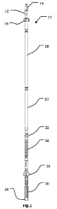
[0035] Figures 1 and 2 are side views of a running gear assembly;
[0036] Figures 3 and 4 are a perspective view and side view, respectively, of
a shock
absorber which may form part of the running gear shown in Figs. 1 and 2. In
these
figures, the shock absorber is illustrated with an end cap sub-assembly
mounted at a
downhole end;
CA 03233873 2024- 4-4
WO 2023/092173
PCT/AU2022/051396
[0037] Figures 5 and 6 are cross-section views of the shock absorber as shown
in
Figs. 3 and 4;
[0038] Figures 7 and 8 are a detailed view and detailed cross-section view,
respectively, of the shock absorber shown in Figs. 3 to 6;
[0039] Figure 9 is an alternative detailed cross-section view of the downhole
end of
the shock absorber shown in Figs. 3 to 8. illustrating a coupling device
arranged to
couple the downhole end to the end cap sub-assembly;
[0040] Figure 10 is a side view of the coupling device shown in Fig. 9,
illustrated in
isolation;
[0041] Figures 11 and 12 arc perspective and cross-section views,
respectively, of a
coupling sub-assembly including the coupling device shown in Fig. 10;
[0042] Figure 13 is an exploded view of the coupling sub-assembly shown in
Figs. 11
and 12;
[0043] Figures 14 and 15 are side views of a releasable coupling assembly
shown in a
locked and unlocked configuration;
[0044] Figures 16 and 17 are cross-section views of the releasable coupling
assembly
shown in Figs. 14 and 15;
[0045] Figures 18 is a side view of an alternative releasable coupling
assembly; and
[0046] Figure 19 is an exploded view of the releasable coupling assembly shown
in
Fig. 18.
CA 03233873 2024- 4-4
WO 2023/092173
PCT/AU2022/051396
11
Description of Embodiments
[0047] In the drawings, reference numeral 10 generally designates a running
gear
assembly 10 for a downhole assembly, such as a wireline assembly deployable
into a
borehole for downhole surveying, and/or for retrieving a core barrel assembly
(not
illustrated).
[0048] In the embodiment illustrated in Figs. 1 and 2, the running gear 10
includes a
plurality of components connected together in series along a common axis. At
an
uphole end 12 is a wireline retrieval connector configured to be connected to
a wireline.
In one embodiment, the wireline retrieval connector is a spear point structure
14. In
other embodiments (not illustrated), the connector additionally or
alternatively includes
an eyelet arranged to connect to the wireline. Arranged downstream of the
spear point
14 is a first centraliser 16 shaped to arrange the running gear 10 centrally
in a drill
string (not illustrated), a downhole tool 18, and a battery 20. The downhole
tool 18 is
typically configured as a data acquisition tool or instrument configured for
wireline
retrieval and used for exploration or mining. The tool 18 typically includes
one or
more sensors operable to record or measure parameters downhole to generate
data. In
the illustrated embodiments, the downhole tool 18 is configured as a north
seeking gyro
for downhole surveying however it will be appreciated that the gyro may be
substituted
with a wide range of other downhole tools 18. In the illustrated embodiment,
the
battery 20 is shown adjacent from and separate to the tool 18. It will be
appreciated
that, in other embodiments (not illustrated), the battery 20 and tool 18 are
integrated.
[0049] In the illustrated embodiment 10, a releasable coupling assembly 22 is
arranged downstream of the battery 20. As will be described in greater detail
below,
the coupling assembly 22 is operable to allow decoupling adjacent components
of the
running gear assembly 10 to sever the running gear 10 into two discrete
portions. In
some embodiments (not illustrated), the running gear 10 includes more than one
coupling assembly 22 to allow breaking the running gear 10 into three, or more
portions, and in other embodiments (not illustrated), the coupling assembly 22
is absent
from the running gear 10. It will be appreciated that the location of the
coupling
CA 03233873 2024- 4-4
WO 2023/092173
PCT/AU2022/051396
12
assembly 22 downstream of the battery 20 to couple the battery 20 and a shock
absorber 24 is exemplary and that, in other embodiments, the coupling assembly
22
may be alternatively positioned and/or configured within the running gear 10,
such as
upstream of, and/or integrated to, the downhole tool 18 to allow coupling the
tool 18 to
an uphole component.
[0050] The shock absorber 24 is arranged downstream of the downhole tool 18
and
coupling assembly 22. As will be described in greater detail below, the shock
absorber
24 is arranged to be compressed when a downhole end 28 of the running gear 10
collides with another object, such as a core barrel assembly or the bedrock,
to reduce
force being transmitted to the downhole tool 18.
[0051] Downstream of the shock absorber 24 is a second centraliser 26 shaped
to
arrange the running gear 10 centrally in the drill string, and, at a downhole
end 28, is an
overshot 30. The overshot 30 is operable to automatically engage another
structure,
such as a spear point or eyelet, upon impact with the structure. For example,
when the
running gear 10 is lowered by wireline sufficiently far into the borehole, the
overshot
30 is operable to engage a wireline retrieval connector of a core barrel
assembly. Once
engaged with the core barrel assembly, the running gear 10 can be retrieved by
reeling
in the wireline to lift the core barrel assembly to the surface.
[0052] It will be appreciated that the running gear assembly 10 is
configurable to have
more, or less, components than the embodiment shown in Figure 1, such as to
suit
particular use requirements. For example, in some embodiments (not
illustrated), the
running gear assembly 10 includes a wireline retrieval connector arranged at
an uphole
end of the assembly 10, a downhole tool arranged downstream of the wireline
retrieval
connector, the shock absorber 24 arranged downstream of the downhole tool, and
the
overshot 30 arranged at a downhole end of the assembly. In other embodiments
(not
illustrated), the running gear assembly 10 includes a wireline retrieval
connector
arranged at an uphole end of the assembly 10, a downhole tool arranged
downstream of
the wireline retrieval connector, an alternative shock absorber arranged
downstream of
the downhole tool, the coupling device 64, described below, arranged
downstream of
CA 03233873 2024- 4-4
WO 2023/092173
PCT/AU2022/051396
13
the downhole tool to couple two axially adjacent components of the assembly,
and the
overshot 30 arranged at a downhole end of the assembly. In yet other
embodiments
(not illustrated), the running gear assembly 10 includes a wireline retrieval
connector
arranged at an uphole end of the assembly 10, a downholc tool arranged
downstream of
the wireline retrieval connector, the releasably coupling assembly 22 arranged
upstream
or downstream of the downhole tool, a shock absorber arranged downstream of
the
releasable coupling assembly, and the overshot 30 arranged at a downhole end
of the
assembly.
[0053] Figs. 3 to 9 illustrate the shock absorber 24 connected to an end cap
sub-
assembly 63 in isolation. In these figures, the shock absorber 24 is
configured for
impact, via the end cap sub-assembly 63, with other objects or structures,
such as
bedrock. It will be appreciated that the shock absorber 24 is configurable to
fit to, or
form part of, alternative downhole assemblies to the running gear 10,
configured for
diamond drilling or reverse circulation (RC) drilling.
[0054] In the illustrated embodiment, and best shown in Fig. 5, the shock
absorber 24
includes a downhole portion 32 defining a bore 34, and an uphole portion 36
configured for direct or indirect connection to the downhole tool 18. The
uphole
portion 36 has a stanchion 38 extending from one end and which carries a
piston 40.
The piston 40 is slidably engaged with the bore 34 to allow relative axial
movement of
the uphole portion 36 and the downhole portion 32. A first resiliently
deformable
member, in the form of an outer compression spring 42, is arranged between the
uphole
portion 36 and the downhole portion 32. The spring 42 is arranged to be
compressed
when the uphole portion 36 and downhole portion 32 move axially relative to
each
other in a first direction. A second resiliently deformable member, in the
form of an
inner compression spring 44, is arranged between an end of the bore 34 and the
piston
40 to be compressed when the uphole portion 36 and downhole portion 32 move
axially
relative to each other in a second direction opposed to the first direction.
[0055] The outer spring 42 is arranged to act as a bound spring to absorb
energy when
the uphole portion 36 and piston 40 move in the first direction relative to
the downhole
CA 03233873 2024- 4-4
WO 2023/092173
PCT/AU2022/051396
14
portion 32, typically being a downhole direction, such as is caused by the
shock
absorber 24, or connected running gear 10, impacting a core barrel assembly.
The
inner spring 44 is arranged to act as a rebound spring to absorb energy when
the uphole
portion 36 and piston 40 move in the second direction relative to the downhole
portion
32. typically being an uphole direction, immediately after the bound stroke.
It will be
appreciated that configuring the resiliently deformable members as springs 42,
44 is
exemplary and that configuring these members in other ways, such as
elastomeric
sleeves, is within the scope of this disclosure.
[0056] The downhole portion 32 has one or more abutment surfaces 46 arranged
to
abut the piston 40 to limit relative axial movement of the uphole portion 36
and the
downhole portion 32. The abutment surface(s) 46 are arranged at a specific
position
along the bore 34 to restrict movement of the piston 40 in the second
direction. This
position is based on a determined limit of compression of the spring 44 which
causes
damage to the spring 44. The arrangement of the abutment surface(s) 46
therefore
inhibits or prevents the inner spring 44 being compressed sufficiently to
damage the
spring 44. This can prove useful where the shock absorber 24 is arranged such
that
significant force is exerted axially through the shock absorber 24 to tension
the shock
absorber 24. This may occur when the shock absorber 24 is fitted in the
running gear
and the running gear 10 is connected to and lifting a core barrel assembly.
This may
also occur where the shock absorber 24 directly connects to another downhole
component and moved to lift the component from the borehole. It will be
appreciated
that, in some embodiments (not illustrated), tensioning the shock absorber 24,
such as
to lift another connected component, is not required, and therefore no
abutment surface
46 is present.
[0057] In the illustrated embodiment, the abutment surface(s) 46 is defined by
an
annular shoulder 48 arranged to extend into the bore 34 and at least partially
surround
the second resiliently deformable member, being the inner spring 44. The
shoulder 48
is arranged to face an uphole oriented side of the piston 40 to allow the
piston to collide
with, and prevent passing, the shoulder 48 when moving in the second
direction. In
other embodiments (not illustrated), the abutment surfaces 46 are defined by a
CA 03233873 2024- 4-4
WO 2023/092173
PCT/AU2022/051396
continuous or discontinuous shoulder defined by the downhole portion 32. This
may
include one or more protrusions, such as fins, splines, or ribs, integrally
formed with, or
connected to, the downhole portion 32 to extend into the bore 34. In yet other
embodiments (not illustrated), the abutment surfaces 46 are defined by one or
more
protrusions, such as a boss or pins, arranged to extend from an end of the
bore 34
between the spring 44 and the stanchion 38.
[0058] The shoulder 48 is defined by an annular collar or ring 50 fixedly
mounted to
the downhole portion 32 at a defined location along the bore 34 to surround
the inner
spring 44 to define a single abut surface 46. In this embodiment, the collar
50 is
trapped between two bodies 53, 54 of the downhole portion, where threadedly
engaging
the bodies 53, 54 secures the collar 50 along the bore 34 in a pocket defined
in one of
the bodies 54 arranged to seat the collar 50. The collar 50 defines a
continuous annular
shoulder 48 arranged as a seat for a rim of the piston 40. In some
embodiments, the
collar 50 comprises a plurality of discrete portions (not illustrated), such
as forming
segments arranged in an annular array about the bore 34, to define a
discontinuous
annular shoulder 48.
[0059] In some embodiments (not illustrated), the axial position of the collar
50
relative to the bore 34 is adjustable by operating an adjustment mechanism,
such as
positioning the collar 50 along a thread defined by part of the downhole
portion 32.
Such embodiments may allow adjusting the compression limit of the inner spring
44,
for example, to adapt the shock absorber 24 for different load requirements[.
[0060] Best shown in Fig. 6, the piston 40 carries a resiliently deformable
body 52
arranged across a downhole end of the piston 40 to allow abutting an end 54 of
the bore
34 to be compressed. The body 52 acts as a buffer arranged to absorb force at
the
maximum extent of travel of the piston 40 in the first direction. This can
inhibit the
outer spring 42 being compressed sufficiently to cause damage to the spring
42, and/or
prevent the piston 40 colliding with the end 54 of the bore 34. The body 52 is
typically
configured to have a stiffness greater than the stiffness of the outer spring
42 to
enhance protecting the spring 42. In some embodiments, the body 42 is formed
from
CA 03233873 2024- 4-4
WO 2023/092173
PCT/AU2022/051396
16
an elastomer having a specific shore hardness configured to enhance wear
resistance,
such as being around 80A to 100A.
[0061] The body 52 defines a double-curved end face 56 which can enhance
deformation of the body 52 and consequently dissipating force through the body
52. It
will be appreciated that the double-curved end face 56 structure is exemplary,
and that
the end face 56 is configurable in other ways, such as defining domes, or
carrying a
layer of second, less dense material, to enhance buffering.
[0062] Best shown in Figs. 7 and 8, the downhole portion 32 defines at least
one first
flush port 58 at, or proximal to, each end of the bore 34. In the illustrated
embodiment,
the downhole portion 52 defines at least one second flush port 60 arranged
between the
first flush ports 58. Each flush port 58, 60 is arranged to convey fluid from
within the
bore 34 to outside of the downhole portion 32. This allows air and/or
particulate, such
as drilling fluid or mud, to be urged out of the bore 34 by the piston 40
travelling in the
first or second direction along the bore 34. This arrangement can
advantageously
provide a self-cleaning function whereby movement of the piston 40 maintains a
clear
path through the bore 34. This can be particularly useful where the shock
absorber 24
is operated in environments containing particulate which can collect and
harden at the
ends of the bore 34 which can inhibit movement of the piston 40 and
potentially cause
downtime to maintain the shock absorber 24.
[0063] Each flush port 58, 60 is dimensioned to allow particulate, such as
drill
cuttings, to be flushed from the bore 34 by the moving piston 40. The flush
ports 58,
60 may define a minimum width or diameter of around 10 mm. The flush ports 58,
60
may also define a maximum width of around 15 mm to prevent a user from
inserting a
finger into the bore 34.
[0064] The second flush port 60 is configured to define an elongate slot
extending in
an axial direction partway along the bore 34. It will be appreciated that, in
other
embodiments (not illustrated), the first and/or second flush ports 58, 60
define
CA 03233873 2024- 4-4
WO 2023/092173
PCT/AU2022/051396
17
alternative shapes, such as triangular or elliptical, and may include a linear
and/or
annular array of flush ports 58, 60.
[0065] Best shown in Fig. 9, the end cap sub-assembly 63 is mounted at an end
of the
downhole portion 32 of the shock absorber 24 by a coupling device 64. The
coupling
device 64 is connected between a sleeve 62 of the sub-assembly 63 and the
downhole
portion 32 to coaxially align the downhole portion 32 and the sleeve 62. The
coupling
device 64 includes a frangible portion, in the illustrated embodiments in the
form of a
necked region 66, configured to fracture when force exerted through the device
62
exceeds a defined threshold. Fracturing the frangible portion 66 separates the
downhole portion 32 from the sleeve 62 to release the shock absorber 24 from
the end
cap sub-assembly 63. Where the shock absorber 24 is connected, via the
coupling
device 64, at its downhole end to another component or assembly which becomes
stuck
in the drill string, the arrangement and configuration of the coupling device
64 will
cause the necked region 66 to break when the vvireline is tensioned beyond the
defined
threshold, consequently allowing retrieval of the shock absorber 24 from the
drill
string.
[0066] Fig. 10 illustrates the coupling device 64 in isolation. The coupling
device 64
has an elongate body 68 defining a longitudinal axis, and a pair of engagement
structures 70 spaced along the axis, each structure 70 being configured to
engage
axially adjacent components of a downhole assembly, such as the downhole
portion 32
of the shock absorber 24 and the sleeve 62 of the end cap sub-assembly 63, as
shown in
Fig. 9. It will be appreciated that the coupling device 64 is not limited to
coupling
components of the shock absorber 24 and may be used to couple other downhole
components, as will he described in greater detail below.
[0067] A first engagement structure 70 is arranged at one end of the device 64
and in
the form of a threaded portion 72 to allow threadedly engaging another
component. A
second engagement structure 70 is spaced partway along the device 64 and in
the form
of a flange 74 to allow frictionally engaging another component. It will be
appreciated
CA 03233873 2024- 4-4
WO 2023/092173
PCT/AU2022/051396
18
that the configuration of these structures 70 is exemplary and that other
structures
suitable for engaging another component are within the scope of this
disclosure.
[0068] The flange 74 includes a surface 76 extending perpendicularly to the
longitudinal axis of the body 68 to allow frictionally engaging another
component. The
flange 74 is configured such that in use, the surface 76 is arranged to face
uphole to
facilitate lifting the engaged component.
[0069] The necked region 66 is arranged between the engagement structures 70
and
configured to fracture when the device 64 is exposed to tensile force
exceeding a
defined threshold. In other embodiments (not illustrated), the device 64
additionally or
alternatively includes a frangible portion configured to fracture by shearing
when the
device 64 is exposed to tensile force exceeding a defined threshold, such as
including a
weakened region of the flange 74. In yet other embodiments (not illustrated),
the
device 64 additionally or alternatively includes a frangible portion
configured to
fracture when the device 64 is exposed to torsional force exceeding a defined
threshold.
The threshold is specified according to the usage requirements of the device
64. This
may be, for example, fracture at 20,000 N with a tolerance of +/- 1,000 N. In
some
embodiments, the threshold is defined as a percentage of the typical maximum
rated
load of a tool which the device 64 is connected to.
[0070] Figs. 11 to 13 show the coupling device 64 arranged in a coupling sub-
assembly 80 for a downhole assembly, such as the running gear 10. The coupling
sub-
assembly 80 includes a first member, in the form of a sleeve 82 defining a
recess 84 in
one end, and a second member, in the form of a shaft 86 having a projection 88
dimensioned to be received in the recess 84 of the sleeve 82. The shaft 86 is
configured to be rotationally locked relative to the sleeve 82. The coupling
device 64 is
connectable between the sleeve 82 and the shaft 86 to coaxially align these
components.
[0071] Best shown in Fig. 13, the sleeve 82 defines a keyway 90 adjacent the
recess
84, and the shaft 86 defines a key seat 92. The sub-assembly 80 also includes
a key 94
CA 03233873 2024- 4-4
WO 2023/092173
PCT/AU2022/051396
19
dimensioned to be received in the keyway 90 and the key seat 92 to inhibit
relative
rotation of the first sleeve 82 and the second sleeve 86. It will be
appreciated that, in
other embodiments (not illustrated), the key 94 may be integrally formed with
the
second sleeve 86 such that the key seat 92 is absent. It will also be
appreciated that the
arrangement of the key 94, key seat 92 and key way 90 are one approach to
rotationally
lock the sleeves 82, 86 relative to each other and that other approaches are
within the
scope of this disclosure. For example, in some embodiments (not illustrated),
the
projection 88 defines a hex section and the recess 84 defines a complementary
hex
recess. In yet other embodiments (not illustrated), the projection 88 and
recess 84
define alternatively shaped complementary structures to inhibit relative
rotation but
allow relative axial movement.
[0072] Returning to Fig. 9, the shock absorber 24 includes at least some of
the
features of the coupling sub-assembly 80. It will be appreciated that common
reference
numerals indicate common features. In this embodiment, the downhole portion 32
defines the keyseat 92 and the downhole sleeve 62 defines the keyway. The key
94 is
housed in the keyseat 92 and the keyway 94 to inhibit relative rotation of the
downhole
portion 32 and downhole sleeve 62.
[0073] Figs. 14 to 19 illustrate a releasable coupling assembly 100 for
releasably
coupling axially adjacent components of a downhole assembly, such as a
downhole tool
and a shock absorber. It will be appreciated that the releasable coupling
assembly 100
is configurable to fit to, or form part of, alternative downhole assemblies to
the running
gear 10, such as is used for RC drilling. The releasable coupling assembly 100
includes
a downhole body 102 configured to connect to one of the axially adjacent
components,
and an uphole body 104 configured to connect to the other of the axially
adjacent
components. Each of the downhole body 102 and the uphole body 104 have a
complementary engagement structure 106 configured to releasably engage the
bodies
102, 104. The coupling assembly 100 also includes a sleeve 108 rotatably
mounted on
one of the downhole body 102 and the uphole body 104. The sleeve 108 is
configured
to be manually rotatable to axially translate between a locked position (Figs.
14 and 16)
to cover the engagement structures 106, and an unlocked position (Figs. 15 and
17) to
CA 03233873 2024- 4-4
WO 2023/092173
PCT/AU2022/051396
expose the engagement structures 106 to allow uncoupling the axially adjacent
components.
[0074] Figs. 14 to 17 illustrate a first embodiment 110 of the releasable
coupling
assembly 100, and Figs. 18 and 19 illustrate a second embodiment 22 of the
assembly
100, being the releasable coupling assembly 22 shown in Fig. 1 forming part of
the
running gear assembly 10. Whilst this embodiment 22 is shown fitted to the
running
gear assembly 10 it will be appreciated that this embodiment 22, and the first
embodiment 110, can be employed to releasably couple any axially adjacent
components of downhole assemblies, and are not limited to use within the
running gear
assembly 10. It will be understood that the two embodiments 110, 22 share
features
and that common reference numerals indicate common features.
[0075] The sleeve 108 defines a helical slot 107 arrange to extend partway
around the
sleeve 108 . Each uphole body 104 includes a radially extending shaft 105
dimensioned to be received in the slot 107. Rotating the sleeve 108 between
the
locked position and the unlocked position causes sidewalls of the slot 107 to
ride along
the shaft 105 to guide movement of the sleeve 108.
[0076] Best shown in Figs. 16 and 17, each embodiment 22, 110 includes a
retention
mechanism 130 operable to retain the sleeve 108 in the locked position or the
unlocked
position. The sleeve 108 defines at least one downhole recess 132 arranged
adjacent
one end, and at least one uphole recess 134 atTanged adjacent the other end,
and the
retention mechanism 130 includes a detent structure biased to extend radially
to allow
engaging the at least one downhole recess 132 or the at least one uphole
recess 134. In
the illustrated embodiment, the detent structure comprises a pair of bearings
136 urged
outwardly from the uphole body 104 by a compression spring 137 housed in the
uphole
body 104. It will be appreciated that, in other embodiments (not illustrated),
the
retention structure is alternatively configured to allow engaging the sleeve
108 in the
locked and unlocked positions, such as including a leaf or bow string to urge
an
engagement structure radially to allow engaging the sleeve 108.
CA 03233873 2024- 4-4
WO 2023/092173
PCT/AU2022/051396
21
[0077] Best shown in Fig. 19, the engagement structures 106 of each of the
illustrated embodiments 22, 110 are configured to slidably interlock such
that, when the
sleeve 108 is rotated to the unlocked position to exposes the structure 106,
decoupling
requires moving the bodies 102, 104 transverse to a longitudinal axis of the
assembly
22. 110. The downhole body 102 defines a keyed portion 112 and the uphole body
104
defines a complementary shaped slot 114 for receiving the keyed portion 112.
The
keyed portion 112 defines a flared free end 116 arranged to inhibit
withdrawing the
keyed portion 112 from the slot 114 in an axial direction. The keyed portion
112 also
defines a tapered base 118 to further enhance engagement between the bodies
102, 104.
[0078] The uphole body 104 of the second embodiment 22 includes a wireline
retrieval connector including a spear point structure 120. In other
embodiments (not
illustrated), the wireline retrieval connector includes an eyelet. Configuring
the uphole
body 104 in this way allows rapidly connecting the body 104 to a conventional
releasable engagement mechanism, such as an overshot. Where the coupling
assembly
22 is arranged partway along an elongate downhole assembly, such as the
running gear
illustrated in Fig. 1, operating the coupling assembly 22 allows splitting the
downhole assembly into two portions, reattaching the uphole body 104 to the
coupling
assembly 22 , and connecting an overshot to the spear point structure 120 to
continue
extracting the downhole assembly from a drill string.
[0079] Use of the running gear assembly 10 typically involves activating the
downhole tool 18 and deploying the assembly 10 into a drill string or borehole
by
suspending the assembly by a wireline (not illustrated) connected to the spear
point
structure 14, typically via a further overshot (not illustrated). As the
assembly 10
descends into the drill string or borehole, the downhole tool 18 records or
measures
parameters to generate and store data. Measured parameters are typically
geophysical,
geological, geonaechanical, and/or navigational parameters, including, but not
limited
to, dip, azimuth, ganuna, magnetic susceptibility, density, porosity,
electrical
resistivity, temperature, acceleration, pressure, acoustic velocity, magnetic
field
measurements. The assembly 10 is lowered until the overshot 30 collides within
another component, typically being a backend of a core barrel assembly,
causing
CA 03233873 2024- 4-4
WO 2023/092173
PCT/AU2022/051396
22
operation of the shock absorber 24, described in greater detail below. The
collision
causes the overshot 30 to automatically engage the component. The running gear
assembly 10 is then retrieved to the surface by retracting the wireline, again
causing
operation of the shock absorber 24.
[0080] Where the releasable coupling assembly 22 forms part of the running
gear
assembly 10 and is revealed duration extraction of the running gear 10 from
the
borehole or drill string, the releasable coupling assembly 22 may be operated
by an
operator manually rotating the sleeve 108 to the unlocked position to expose
the
engagement structures 106. The operator then secures the downhole body 102
relative
to the surface, such as by inserting a pin through a component of the assembly
10, and
operates the engagement structures 106 to separate the uphole body 104 from
the
downhole body 102, consequently splitting the running gear assembly 10 into a
portion
arranged out of the hole, and a portion arranged in the hole. The uphole body
104 is
then re-engaged with the downhole body 102, the sleeve 108 returned to the
locked
position, and the further overshot engaged with the spear point structure 120.
The
remainder of the running gear assembly 10 is then extracted.
[0081] Use of the shock absorber 24 involves the shock absorber 24 being
lowered
down a borehole or drill string until the downhole portion 32 collides,
directly or
indirectly via one or more connected components, with a static object, such as
a core
barrel assembly. The collision inhibits further movement of the downhole
portion 32 in
the downhole direction, causing the uphole portion 36 to move in the first
direction
relative to the downhole portion 32. This movement causes the piston 40 to
travel
along the bore 34 to expel fluid, and potentially also particulate, from the
flush ports
58, 60, and cause the uphole portion 36 to compress the outer (bound) spring
42. Some
collision may cause the resiliently deformable body 52 to press against the
downhole
end 54 of the bore 34. The piston 40 may then travel in the second direction
causing
compression of the inner (rebound) spring 44. Once connected to another
object, such
as the core barrel assembly, the shock absorber 24 may be lifted from the
borehole or
drill string, causing the piston 40 to travel in the second direction until
abutting the
CA 03233873 2024- 4-4
WO 2023/092173
PCT/AU2022/051396
23
abutment surface 46 of the collar 50, where the piston 40 is inhibited from
further
movement in the second direction.
[0082] During extraction of the running gear assembly 10 from the borehole or
drill
string, the running gear 10, or a component connected to the running gear 10,
such as a
core barrel assembly, may become jammed. Should tension continue to be applied
to
the wireline and the tensile force exceed the defined threshold of the
coupling device
64, this causes the necked region 66 to fracture. The fracture of the device
64
uncouples the downhole sleeve 62 from the remainder of the shock absorber 24,
allowing retrieval of the shock absorber, and all components of the running
gear 10
upstream of the shock absorber 24, including the downhole tool 18, to the
surface.
[0083] It will be appreciated by persons skilled in the art that numerous
variations
and/or modifications may be made to the above-described embodiments, without
departing from the broad general scope of the present disclosure. The present
embodiments are, therefore, to be considered in all respects as illustrative
and not
restrictive.
CA 03233873 2024- 4-4