Note: Descriptions are shown in the official language in which they were submitted.
WO 2023/039241
PCT/US2022/043204
Intrauterine Contraceptive Device
[0001] Various embodiments of a contraceptive intrauterine device and methods
for using it
have been disclosed above. These various embodiments may be used alone or in
combination, and various changes to individual features of the embodiments may
be altered,
without departing from the scope of the invention. For example, the order of
various method
steps may in some instances be changed, and/or one or more optional features
may be added
to or eliminated from a described device. Therefore, the description of the
embodiments
provided above should not be interpreted as unduly limiting the scope of the
invention as it is
set forth in the claims.
FIELD OF THE INVENTION
[0002] The invention relates generally to medical devices. More specifically,
the invention
relates to an intrauterine device for contraception and method for use.
BACKGROUND
[0003] Intrauterine devices (IUDs) are a commonly used form of contraception.
There are
two basic types of currently available IUDs--copper-releasing and progesterone-
releasing.
The copper IUD is a T-shaped device made of polyethylene wrapped with copper
wire. The
device acts as a foreign body within the uterus and releases copper to produce
a chemical
effect on the endometrium of the uterus and to alter the production of
cervical mucus, thus
producing a spermicidal environment.
[0004] Progesterone-releasing IUDs are also T-shaped devices and include a
cylindrical
reservoir containing levonorgestrel, which is released into the uterus over
time. The
levonorgestrel adds to the foreign body effects to create added spermicidal
action and also
thickens cervical mucus to act as a barrier to sperm penetration into the
uterus.
1
CA 03233945 2024- 4-4
WO 2023/039241
PCT/US2022/043204
[0005] Although both copper and progestin-releasing IUDs work well for
contraception, both
have common side effects. The most common side effects with copper IUDs are
abnormal
bleeding and pain. The most common side effects with levonorgestrel IUDs are
hormone-
related effects, such as headaches, nausea, breast tenderness, depression and
cyst formation.
When either copper or hormone/levonorgestrel is used as an active ingredient,
it is typically
thought that the larger the surface area of copper or hormone exposed in the
uterus, the better
the contraceptive action of the IUD. Although a larger surface area of exposed
copper or
hormone creates a higher risk of abnormal bleeding or other side effects, it
is thought to be
necessary to achieve effective birth control. Thus, for example, currently
available copper
IUDs typically have an exposed copper surface area of 380 mm squared. Past
scientific
studies of similarly configured IUDs, but with a reduced copper surface area
of 200 mm
squared, showed higher failure rates (undesirable pregnancies) in the range of
3%-10%.
[0006] In addition to the above shortcomings, many currently available IUDs
are at least
slightly uncomfortable and/or challenging to deliver into the uterus. All IUDs
are delivered
through the cervix using a delivery sheath. Although this delivery method
works well in
many cases, the required size of the currently available IUDs typically
requires a sheath
having an outer diameter that can cause pain or discomfort upon insertion into
a cervix. In
some cases, the pain can even be significant. Thus, the size of currently
available IUDs and
their delivery sheaths is another shortcoming.
[0007] Therefore, although existing IUDs work relatively well for their
purpose of
contraception, there is still a need for improved IUDs. Ideally, such improved
IUDs would
provide reliable, long-acting contraception with relatively few, minor side
effects. At least
some of these objectives are met by the embodiments described in this
application.
BRIEF SUMMARY
2
CA 03233945 2024- 4-4
WO 2023/039241
PCT/US2022/043204
[0008] Based on the various drawbacks of currently available IUDs, various
embodiments of
IUDs described herein provide contraception without the use of copper,
levonorgestrel, other
hormones or other substances. These IUDs provide contraception by providing an
effective
foreign body response within the uterus and in some cases by applying pressure
against the
uterine wall. The IUDs described herein are generally made at least in part of
shape memory
material, such as but not limited to Nitinol.
[0009] In other embodiments described herein, an IUD may deliver copper and/or
another
spermicide in a targeted fashion to one or more targeted areas within the
uterus. For example,
in one embodiment, copper may be focally delivered by at IUD at or near
openings of the
fallopian tubes and at or near the cervical os. By delivering a substance more
selectively (or
"focally"), these IUD embodiments provide effective contraception with smaller
doses of
copper (or other substance) than currently available IUDs. Generally, the
limited, focal
delivery of a substance such as copper is augmented by the IUD acting as a
foreign body
within the uterus, thus providing effective contraception.
[0010] In one aspect, a method for promoting contraception by placing a
contraceptive device
within a uterus without blocking fallopian tubes may include advancing a
distal end of a
delivery device through a cervix, advancing the contraceptive device
comprising an elongate
shape memory member out of the distal end of the delivery device and into the
uterus, and
limiting inferior migration of the contraceptive device within the uterus.
Advancing the
contraceptive device out of the distal end of the delivery device may cause
the device to
expand from a first, compressed shape within the delivery device to a second,
expanded
shape within the uterus. In the expanded shape, two tissue contact surfaces at
opposite ends
of the shape memory member may contact the inner wall of the uterus, and each
of the tissue
contact members, when the contraceptive device is delivered, may be positioned
near, but not
within, an opening of one of the two fallopian tubes branching from the
uterus. Inferior
3
CA 03233945 2024- 4-4
WO 2023/039241
PCT/US2022/043204
migration may be limited by allowing the contraceptive device to assume a
third shape, when
subjected to pressure that tends to cause a downward migration of the device
within the
uterus, in which the tissue contact members are closer together than in the
second shape and
in which an expandable middle portion of the device is expanded to contact the
inner wall of
the uterus and thus limit the downward migration of the device.
[0011] In some embodiments, each of the tissue contact surfaces, when the
device is
delivered, may be positioned within approximately 2 cm of an opening of one of
the fallopian
tubes. Optionally, some embodiments of the method further involve delivering a
substance
within the uterus via the contraceptive device, where the substance may
include but is not
limited to one or more hormones, spermicides, copper and/or therapeutic
agents. In one
embodiment, delivering the substance may involve delivering copper to at least
one selected
area of the uterus in a more concentrated dose than to at least one other area
of the uterus via
at least one substance delivery member disposed on the contraceptive device in
at least one
location configured to provide the substance at the at least one selected
area. In some of such
embodiments, a total exposed surface area of the substance delivery member(s)
may equal no
more than about 200 square millimeters. In some embodiments, the substance
delivery
member(s) may include at least two substance delivery members, and each of the
at least two
substance delivery members may be positioned on the contraceptive device so
that it will be
located at or near an ostium of one of the fallopian tubes when the
contraceptive device is
delivered to the uterus. Optionally, the substance delivery member(s) may
further include at
least one additional substance delivery member positioned on the contraceptive
device so that
it will be located at or near an internal cervical os when the contraceptive
device is delivered
to the uterus.
[0012] In some embodiments, the method may further include removing the
contraceptive
device through the cervix by pulling on a thread connected to the
contraceptive device. In
4
CA 03233945 2024- 4-4
WO 2023/039241
PCT/US2022/043204
some embodiments, the distal end of the delivery device may be tapered, and
the
contraceptive device may be completely contained within the delivery device
during
advancement of the delivery device through the cervix. In some embodiments,
advancing the
contraceptive device out of the delivery device may involve delivering the
contraceptive
device to a first, inferior location in the uterus, and the method may further
include allowing
the contraceptive device to migrate superiorly to a second location in the
uterus after
delivery. In some embodiments, the method may further involve applying
sufficient pressure
against the wall of the uterus with the tissue contact surfaces to promote
contraception
[0013] In another aspect, a method for promoting contraception may involve
delivering a
substance to one or more targeted areas in a uterus in a more concentrated
dose than to at
least one other area in the utenis via a contraceptive device having at least
one substance
delivery member located thereon. In such a method, a total exposed substance
delivery
surface area of the substance delivery member(s) may equal no more than about
200 square
millimeters.
[0014] In some embodiments, the method may also involve, before delivering the
substance,
advancing a distal end of a delivery device through a cervix, and advancing
the contraceptive
device comprising an elongate shape memory member out of the distal end of the
delivery
device and into the uterus, thus causing the contraceptive device to expand
from a first,
compressed shape within the delivery device to a second, expanded shape within
the uterus,
where two tissue contact surfaces at opposite ends of the shape memory member
contact the
inner wall of the uterus when the contraceptive device is in the second shape,
and where each
of the tissue contact members, when the contraceptive device is delivered, is
positioned near,
but not within, an opening of one of the two fallopian tubes branching from
the uterus.
CA 03233945 2024- 4-4
WO 2023/039241
PCT/US2022/043204
[0015] In some embodiments, the substance is copper, and the substance
delivery member(s)
include at least a first substance delivery member positioned on the elongate
member at or
near a first one of the tissue contact surfaces, a second substance delivery
member positioned
on the elongate member at or near a second one of the tissue contact surfaces,
and a third
substance delivery member positioned on the elongate member at or near a
middle portion
configured to be located at or near a cervical os when the contraceptive
device is located
within the uterus. In some embodiments, the method may further include
limiting inferior
migration of the contraceptive device within the uterus by allowing the
contraceptive device
to assume a third shape when subjected to pressure that tends to cause a
downward migration
of the device within the uterus, in which the tissue contact members are
closer together than
in the second shape and in which an expandable middle portion of the device is
expanded to
contact the inner wall of the uterus and thus limit the downward migration of
the device. In
some embodiments, the method may further include applying sufficient pressure
against the
wall of the uterus with the tissue contact surfaces to promote contraception.
[0016] In some embodiments, the substance is copper, and the substance
delivery member(s)
include at least three substance delivery members, two of which are positioned
on the
contraceptive device so that they will be located at or near an ostium of a
fallopian tube and
one of which is positioned on the contraceptive device so that it will be
located at or near a
cervical os when the contraceptive device is delivered to the uterus. In
alternative
embodiments, the substance may be one of any number of spermicidal agents
other than
copper. In some embodiments, the method may further include delivering an
additional
substance to the uterus, where the additional substance may include but is not
limited to
Levonorgestrel, other hormones and/or therapeutic agents. In various
embodiment, the total
exposed surface area of the substance delivery members may equal no more than
about 200
square millimeters.
6
CA 03233945 2024- 4-4
WO 2023/039241
PCT/US2022/043204
[0017] In another aspect, a method for promoting contraception by focally
delivering a
substance within a uterus may first involve advancing a contraceptive device
out of a distal
end of a delivery device and into the uterus, thus causing the contraceptive
device to expand
from a first, compressed shape within the delivery device to a second,
expanded shape within
the uterus, where two tissue contact surfaces at opposite ends of the
contraceptive device
contact an inner wall of the uterus when the contraceptive device is in the
second shape, and
where each of the tissue contact surfaces, when the contraceptive device is
delivered, is
positioned near, but not within, one of two fallopian tube openings. Next, the
method may
involve delivering the substance to at least one targeted area of the uterus
over time, via the
contraceptive device, where the at least one targeted area includes areas at
or near both of the
fallopian tube openings, and where the contraceptive device includes at least
one substance
delivery member located at or near each of the tissue contact surfaces to
deliver the substance
at or near the fallopian tube openings. Finally, the method may also involve
allowing the
contraceptive device to partially collapse within the uterus such that the at
least one substance
delivery member forms a continuous line across the uterus from one side to an
opposite side
of the inner wall of the uterus.
[0018] In some embodiments, the contraceptive device may include at least
three substance
delivery members, and advancing the contraceptive device may cause at least
one of the
substance delivery members to be positioned at or near each of the openings of
the fallopian
tubes and one of the substance delivery members to be positioned at or near a
cervical os. In
some embodiments, delivering the substance comprises delivering copper, and a
total
exposed surface area of the substance delivery members is no more than about
200 square
millimeters. In some embodiments, the contraceptive device may include an
elongate shape
memory member, the substance delivery member(s) may be formed as sleeves
disposed
around the shape memory member, and allowing the contraceptive device to
partially
7
CA 03233945 2024- 4-4
WO 2023/039241
PCT/US2022/043204
collapse causes the substance delivery members to move together to form an
approximately
continuous cylinder.
[0019] In another aspect, a method for approximating contractility of a uterus
may first
involve advancing a contraceptive device comprising a shape memory member out
of the
distal end of a delivery device and into the uterus, thus causing the
contraceptive device to
expand from a first, compressed shape within the delivery device to a second,
expanded
shape within the uterus, where two tissue contact surfaces at opposite ends of
the
contraceptive device contact the inner wall of the uterus when the
contraceptive device is in
the second, expanded shape, and where each of the tissue contact surfaces,
when the
contraceptive device is delivered, is positioned near, but not within, an
opening of a fallopian
tube The method may then involve visualizing, using a visualization device,
the
contraceptive device in the second shape in which a middle portion of the
device is expanded
The method may then involve approximating contractility of the uterus by
comparing an
amount of expansion of the middle portion of the device with a known amount of
expansion
of the middle portion when the device is completely unconstrained. In some
embodiments,
visualizing the contraceptive device may involve using a radiographic
visualization device
positioned outside the uterus and at least a portion of the middle portion of
the contraceptive
device may be radiopaque.
[0020] In another aspect, a shape memory, intrauterine, contraceptive device
may include two
tissue contact surfaces at or near opposing ends of the device, an expandable
middle portion
between the tissue contact surfaces, and a spring portion at or near a
midpoint of the elongate
member. The contraceptive device may be configured to move from a first,
default
configuration when unconstrained to a second, partially collapsed
configuration when the two
tissue contact surfaces are forced toward one another by an inner wall of a
uterus The
8
CA 03233945 2024- 4-4
WO 2023/039241
PCT/US2022/043204
expandable middle portion is expanded in the second shape such that it
contacts the inner
wall of the uterus to help prevent migration of the contraceptive device out
of the uterus.
[0021] In some embodiments, the two tissue contact surfaces, the middle
portion and the
spring portion comprise one shape memory wire. In some embodiments, the spring
portion,
the middle portion, and two arms extending from the middle portion comprise a
shape
memory wire, and the device further includes two tissue contact members, each
of which is
coupled with one of the opposing ends of the shape memory wire to form the
tissue contact
surfaces. In some embodiments, the contraceptive device may include a shape
memory wire
made of a material such as but not limited to Nitiniol, other shape memory
metal alloys
and/or shape memory polymers. In one embodiment, the shape memory wire may
have a
diameter of between about 0.015 inch and about 0.017 inch_ In one embodiment,
the middle
portion may be expandable, in the second shape, to a width approximately equal
to a distance
between the two tissue contact surfaces. In one embodiment, the device may be
compressible
into a third, fully collapsed configuration for positioning within a delivery
sheath having an
inner diameter of between about 2.70 mm and about 2.90 mm.
[0022] Some embodiments may further include a substance coupled with the
device for
delivery to the uterus, such as but not limited to one or more hormones,
spermicides, copper,
zinc and/or therapeutic agents. In some embodiments, the substance may be
coupled with the
device via at least one substance delivery member attached to the device. In
some
embodiments, the substance may be copper, and a total exposed surface area of
the substance
delivery member(s) is no more than approximately 200 square millimeters. In
some
embodiments, the contraceptive device may include a shape memory wire, and the
substance
delivery member(s) may include a first copper sleeve disposed over the shape
memory wire
at or near a first one of the tissue contact surfaces, a second copper sleeve
disposed over the
9
CA 03233945 2024- 4-4
WO 2023/039241
PCT/US2022/043204
shape memory wire at or near a second one of the tissue contact surfaces, and
a third copper
sleeve disposed over the shape memory wire at or near the spring portion.
[0023] In some embodiments, a contraceptive device for focally delivering a
substance in a
uterus may include an elongate shape memory member having two opposing ends
and a
spring portion between the opposing ends and at least one substance delivery
member
disposed along a minority of a length of the shape memory member at a location
to locally
deliver the substance, when the contraceptive device is placed in the uterus,
to at least one of
an area near a fallopian tube or an area near a cervical os.
[0024] In some embodiments, the substance delivery member(s) may include two
substance
delivery sleeves, where each of the sleeves is disposed over the shape memory
member at or
near one of the opposing ends. In some embodiments, the substance delivery
member(s) may
include a substance delivery sleeve disposed over the shape memory member at
or near the
spring portion. In some embodiments, the substance delivery member(s) may
include at least
one substance delivery sleeve disposed over the shape memory member at or near
each of the
opposing ends and at least one substance delivery sleeve disposed over the
shape memory
member at or near the spring portion. In some embodiments, the substance may
include
copper or any of a number of other spermicidal agents. In one embodiment, the
substance is
copper, and the substance delivery members have a total surface area no more
than about 200
square millimeters. Optionally, the device may further include a hormone
delivery member
disposed at a different location along the shape memory member from a location
of the
substance delivery member.
[0025] In another aspect, an intrauterine device for promoting contraception
without blocking
the fallopian tubes may include an elongate shape memory member having two
opposing
ends, a spring portion at approximately a midpoint between the two ends, a
default
CA 03233945 2024- 4-4
WO 2023/039241
PCT/US2022/043204
configuration when released from constraint, and a collapsed configuration
when constrained.
The device may further include least one copper delivery member coupled with
the shape
memory member at or near each of the two ends for focally delivering a
substance to a uterus
in an area at or near openings of the fallopian tubes, where a total exposed
surface area of the
substance delivery members is no more than 200 square millimeters.
[0026] In some embodiments, the shape memory member may further include an
expandable
middle portion that expands when the two opposing ends are forced toward one
another by an
inner wall of the uterus, wherein the expanded middle portion may contact the
wall of the
uterus to help prevent migration of the device out of the uterus. In some
embodiments, the
substance delivery members, when pushed together by the inner wall of the
uterus pushing
together the opposing ends, form an approximately continuous line across the
uterus In some
embodiments, the elongate member is made of a shape memory material, such as
but not
limited to Nitinol, other shape memory metal alloys and/or shape memory
polymers.
[0027] In some embodiments, the two opposing ends may be looped portions of
the elongate
member, and the elongate member may be made of Nitinol. In some embodiments,
the spring
portion may be a spring having at least one coil formed in the elongate
member. In some
embodiments, the device in the collapsed configuration may be sufficiently
small to fit within
a delivery sheath having an inner diameter of between about 2.70 mm and about
2.90 mm. In
some embodiments, the elongate member may have a diameter of between about
0.015 inch
and about 0.017 inch. In some embodiments, the substance delivery member(s)
may include
multiple substance delivery sleeves disposed over the shape memory member. In
some
embodiments, the sleeves may include at least one sleeve at or near one of the
ends, one
sleeve at or near an opposite end, and one sleeve at or near the spring
portion.
11
CA 03233945 2024- 4-4
WO 2023/039241
PCT/US2022/043204
[0028] In another aspect, a contraceptive device that may also be used for
approximating
contractility of a uterus may include an elongate shape memory member having
two opposing
ends, a spring portion at a midpoint of the elongate member, a default
expanded
configuration, and a collapsed configuration. The device may also include two
tissue contact
surfaces, each of which is disposed at one of the opposing ends of the
elongate member and a
middle portion of the elongate member that expands in direct proportion to
compression
pressures acting upon the two tissue contact surfaces such that a separation
distance of the
middle portion of the elongate member may be used to approximate contractility
of the
uterus. Optionally, the device may also include at least one radiopaque marker
or material on
the middle portion of the elongate member to facilitate visualization of the
middle portion
using a radiographic visualization device.
[0029] In another aspect, a contraceptive system may include a shape memory,
intrauterine,
contraceptive device and a delivery device for housing and delivering the
contraceptive
device into the uterus through a cervix. The contraceptive device may include
two tissue
contact surfaces at or near opposing ends of the device and an expandable
middle portion
between the tissue contact surfaces. The contraceptive device may be
configured to move
from a first, default configuration when unconstrained to a second, partially
collapsed
configuration when the two tissue contact surfaces are forced toward one
another by an inner
wall of a uterus, where the expandable middle portion is expanded in the
second shape such
that it contacts the inner wall of the uterus to help prevent migration of the
contraceptive
device out of the uterus. The delivery device may include a shaft having a
tapered distal tip
and a pusher member disposed inside the shaft for at least one of advancing
the contraceptive
device out of the distal tip or maintaining a position of the contraceptive
device within the
shaft while the shaft is retracted.
12
CA 03233945 2024- 4-4
WO 2023/039241
PCT/US2022/043204
[0030] In some embodiments, the contraceptive device may be preloaded into the
shaft of the
delivery device before providing the system to a customer. For example, in
some
embodiments, the contraceptive device may be preloaded through a proximal end
of the shaft
of the delivery device. In some embodiments, the shaft of the delivery device
may have an
inner diameter of no more than about 3.00 mm and an outer diameter of no more
than about
3.40 mm. In some embodiments, the contraceptive device may include a Nitinol
wire. In
some embodiments, the shaft of the delivery device may include an inner
surface having at
least one slot for directing advancement of the contraceptive device out of
the distal tip.
Optionally, the contraceptive device may further include at least one
substance delivery
member for delivering a substance within the uterus. In some embodiments, the
substance is
copper, the substance delivery member(s) include at least one substance
delivery member at
or near each of the tissue contact surfaces, and a total exposed surface area
of the substance
delivery member(s) is no more than about 200 square millimeters.
[0031] These and other aspects and embodiments of the invention are described
in greater
detail below, with reference to the drawing figures.
BRIEF DESCRIPTION OF DRAWINGS
[0032] FIG. 1 is a front view of an intrauterine device (IUD), according to
one embodiment;
[0033] FIGS. 2A-2F show a cross-sectional view of a uterus, cervix and
fallopian tubes,
illustrating a method for delivering an intrauterine device (IUD) into a
uterus, according to
one embodiment;
[0034] FIG. 3 is a front view of an IUD, according to an alternative
embodiment;
13
CA 03233945 2024- 4-4
WO 2023/039241
PCT/US2022/043204
[0035] FIGS. 4A and 4B illustrate a method for using the IUD of FIG. 3,
according to one
embodiment;
[0036] FIG. 5 is a front view of an IUD including copper sleeves for focal
copper delivery,
according to one embodiment;
[0037] FIGS. 6A and 6B are front and perspective views, respectively, of an
IUD including
copper sleeves for focal copper delivery, according to an alternative
embodiment;
[0038] FIGS. 7A and 7B are cross-sectional views of a uterus, showing an
insertion location
and a migrated location of an IUD such as that shown in FIGS. 6A and 6B,
according to one
embodiment;
[0039] FIGS. 8A and 8B are cross-sectional views of a uterus, showing expanded
and
partially contracted views of an IUD including copper sleeves for focal copper
delivery,
according to one embodiment;
[0040] FIGS. 9A-9D are front, bottom, side and perspective views,
respectively, of an IUD
including copper sleeves for focal copper delivery, according to another
alternative
embodiment; and
[0041] FIG. 10 is a perspective view of an IUD delivery device, according to
one
embodiment
DETAILED DESCRIPTION
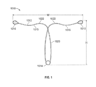
[0042] Referring to FIG. 1, in one embodiment, a contraceptive intrauterine
device (IUD)
1010 may include a shape memory, elongate member 1012 and two tissue contact
members
1016, 1018 disposed at opposite ends of elongate member 1012. Elongate member
1012 may
include a spring portion 1014, typically but not necessarily disposed
approximately at a
midpoint between the opposite ends of elongate member 1012, an expandable
middle portion
14
CA 03233945 2024- 4-4
WO 2023/039241
PCT/US2022/043204
1020, two arms 1015 extending from middle portion 1020, and bends 1022 between
middle
portion 1020 and arms 1015. All or a part of each tissue contact member 1016,
1018 may
comprise a tissue contact surface, in other words, a surface that typically
contacts an inner
wall of a uterus when IUD 1010 is deployed in the uterus.
[0043] Elongate member 1012 is manufactured from a resilient, shape memory
material, such
as but not limited to Nitinol (nickel titanium alloy), spring stainless steel,
other shape
memory metal alloys, shape memory polymers, or the like, and has a default (or
"predetermined") expanded configuration as shown in FIG. 1. Elongate member
1012 may be
compressed into a low profile, collapsed configuration, to facilitate
preloading of IUD 1010
into a delivery sheath and delivery of IUD 1010 through a cervix via the
sheath. When
released from compression within the uterus, IUD 1010 springs back into its
default
expanded configuration to allow tissue contact members 1016, 1018 to contact
the uterine
wall and, by the force inherent in its shape memory material, apply sufficient
pressure against
the inner wall of the uterus to maintain IUD 1010 in position within the
uterus. In many
cases, IUD 1010 may not spring back into its fully expanded, default
configuration when
delivered into the uterus, due to force applied upon it by the uterine wall.
Thus, it is possible
to discuss an "expanded configuration" of IUD 1010 without necessarily meaning
that it is
fully expanded to it default configuration.
[0044] In some embodiments, IUD 1010 may be configured to assume a partially
collapsed
configuration, in which the uterine wall has pushed the two tissue contact
members 1016,
1018 together to cause middle portion 1020 to expand laterally. This partially
collapsed
configuration is described in further detail below. Generally, this
configuration may occur
when forces applied by the uterine wall cause IUD 1010 to migrate slightly in
an inferior
direction (i e , toward the cervical os) As middle portion 1020 expands, it
may help prevent
CA 03233945 2024- 4-4
WO 2023/039241
PCT/US2022/043204
further inferior migration by contacting the inner uterine wall and thus
acting as a stop
mechanism.
[0045] In its fully expanded configuration, such as in FIG. 1, (or when
partially expanded)
IUD 1010 in some embodiments applies outwardly directed pressure against the
uterine wall
that is sufficient only to help maintain IUD 1010 in a desired location in the
uterus and
prevent or at least limit inferior migration. In these embodiments, IUD 1010
provides
contraceptive effect primarily or exclusively by acting as a foreign body in
the uterus. In
alternative embodiments, IUD 1010 may apply a greater amount of pressure
against the
uterine wall, such that the applied pressure helps facilitate or enhance the
contraceptive
effect. Various embodiments of IUD 1010 described herein may thus be "pressure-
applying"
or "non-pressure-applying," but in either case they will be configured to
provide effective
contraception. Thus, any particular embodiment described herein should not be
interpreted to
limit the claims to a particular amount of pressure applied to a uterus,
unless such limitation
is specifically set forth in a claim.
[0046] As illustrated in FIG. 1, in one embodiment, spring portion 1014 is
disposed at the
vertex (or bottom) of elongate member 1012, middle portion 1020 extends upward
from
spring portion 1014 in approximately an elongate oval shape, elongate member
1012 crosses
over itself and forms bends 1022, and then it extends into arms 1015. Although
this
configuration is described in reference to this embodiment, IUD 1010 may have
any of a
number of different expanded configurations in alternative embodiments.
Furthermore,
although the term "spring portion" is used to describe a portion of elongate
member 1012 that
helps confer laterally directed pressure to tissue contact members 1016, 1018,
spring portion
1014 is not necessarily a spring. In many of the embodiments, for example,
spring portion
1014 is simply a midpoint of elongate member 1012 that is formed as a loop_ In
other
embodiments, spring portion 1014 may have any of a number of different shapes.
16
CA 03233945 2024- 4-4
WO 2023/039241
PCT/US2022/043204
[0047] IUD 1010 may be said to have a wingspan (or "width") W, as measured
from a tip of
one tissue contact member 1016 to a tip of the other tissue contact member
1018. IUD 1010
may also be said to have a height (or "length") H, as measured from the bottom
of spring
portion 1014 to the tops of tissue contact members 1016, 1018. Wingspan Wand
height H are
generally selected to provide IUD 1010 with a desired amount of laterally
directed pressure at
tissue contact members 1016, 1018, so that IUD 1010 will maintain itself in a
given location
within the uterus and exert sufficient pressure to promote contraception. In
one embodiment,
for example, IUD 1010 may have a height H of between about 25 mm and about 28
mm and
a wingspan W of between about 44 mm and about 46 mm. Alternative sizes may be
provided
to enhance the effectiveness of IUD 1010 in different female anatomies, but
because IUD
1010 is sufficiently resilient and the uterus is typically a closed space, IUD
1010 is generally
a "one size fits all" device.
[0048] As just mentioned, the uterus (or "uterine cavity") is generally not an
open space.
Even though the uterus is typically illustrated as an open space, such as in
FIGS. 2A-2F, this
is simply a schematic illustration, because the uterus itself is a closed
space. IUD 1010
should, therefore, have sufficient laterally directed pressure when released
from a delivery
device within the uterus to expand within the closed uterine cavity. The
uterus is also
typically a moist environment, so IUD 1010 should have sufficient resiliency
to overcome
any surface tension that might hold the opposed surfaces of the inner wall of
the uterus
together. In embodiments in which substances (copper, hormone, etc.) are not
included, it is
also important that IUD 1010 apply sufficient laterally directed pressure to
promote
contraception. It is believed that pressure applied to the inner uterine wall
by tissue contact
members 1016, 1018 may by itself disrupt the uterine environment in such a way
to cause a
spermicidal effect, thus preventing conception. The pressure exerted against
the uterine wall
17
CA 03233945 2024- 4-4
WO 2023/039241
PCT/US2022/043204
by IUD 1010 may cause an inflammatory response, ischemia, compression of the
spiral artery
and/or a combination thereof, and any or all of these may help promote
contraception.
[0049] Finally, IUD 1010 should have sufficient laterally directed pressure to
prevent inferior
migration of the device within the uterus or expulsion of the device from the
uterus. As is
described in greater detail below, IUD 1010 likely has the greatest
contraceptive effect when
it resides in a certain portion of the uterus, so ideally IUD 1010 will have
sufficient outwardly
directed pressure to prevent inferior migration or expulsion of the device. In
some
embodiments, IUD 1010 also has a configuration and applies sufficient force to
promote
superior migration of the device after delivery, which At the same time,
another objective of
IUD 1010 is to prevent perforation of the uterine wall, so IUD 1010 should not
have an
excessive amount of outwardly directed pressure
[0050] IUD 1010 generates laterally directed, expansile pressure due to the
nature of its
resilient, shape memory material (typically but not necessarily Nitinol), the
diameter of its
material, and its default, expanded shape and size, including spring portion
1014. Spring
portion 1014 may in some embodiments be an actual spring or looped portion of
elongate
member 1012, while in alternative embodiments it may be any of a number of
other suitable
shapes that help confer laterally directed pressure to elongate member 1012.
This laterally
directed pressure pushes tissue contact members 1016, 1018 against the uterine
wall with
sufficient pressure that they first move along the wall to a desired location
for promoting
contraception and then maintain their position on (or "adhere to") the wall at
that location.
IUD 1010 may also have a shape, size, lateral pressure, and size and shape of
tissue contact
members 1016, 1018 that help prevent tissue contact members 1016, 1018 from
advancing
(or "migrating") into the fallopian tubes. It may be advantageous for IUD 1010
to avoid
entering the fallopian tubes, because this may facilitate removal of IUD 1010
when desired
Delivery, adherence to the uterine wall and other characteristics of IUD 1010
are described in
18
CA 03233945 2024- 4-4
WO 2023/039241
PCT/US2022/043204
further detail below. By generating adhering pressure against the uterine
wall, IUD 1010
remains in the uterus as a foreign body and provides further contraceptive
effect by the
application of pressure, thus safely preventing unwanted pregnancy.
[0051] As mentioned, in one embodiment, elongate member 1012 is made of
Nitinol. In
various embodiments, the diameter of elongate member 1012 may be selected to
help provide
a desired amount of lateral pressure generation when the device is in the
default expanded
configuration of FIG. 1. For example, in some embodiments, elongate member
1012 may be
a Nitinol wire with a diameter of between about 0.010" and about 0.025" and
more ideally
between about 0.014" and about 0.015".
[0052] In alternative embodiments, resilient materials other than Nitinol may
be used, such as
other shape memory metal alloys, spring stainless steel or the like. Nitinol
is typically
preferred, however, due to its ability to remain in a compressed configuration
(such as in a
delivery catheter) for long periods of time, fully spring back into its
expanded configuration,
and maintain a constant but gentle pressure against the uterine wall for many
years of useful
life of IUD 1010. The material properties of a Nitinol IUD 1010 allow it to be
compressed
into a collapsed or low profile configuration for storage in a delivery
device, stored in that
configuration for long periods of time, and then delivered out of the delivery
device to
assume its default, expanded configuration. Other resilient materials
typically do not retain
their full resilient properties over time in this way, although to the extent
other materials
would serve this purpose they may be used in alternative embodiments. Storing
and/or
packaging IUD 1010 within a delivery device makes its use easier, because the
end user
(typically a physician or physician's assistant) is not required to load the
device into the
delivery device. By contrast, currently available IUDs typically must be
loaded into their
delivery devices by a physician or physician's assistant before use IUD 1010
formed of
Nitinol is also unique in that it provides a constant lateral pressure in
various uterine sizes and
19
CA 03233945 2024- 4-4
WO 2023/039241
PCT/US2022/043204
is thus a "one size fits all device. Constant gentle lateral pressure along
the inner uterine wall
also prevents expulsion of IUD 1010 out of the uterus, which is one of the
potential
complications of currently available IUDs.
[0053] Tissue contact members 1016, 1018 may be comprised of any of a number
of suitable
materials and may have a number of different sizes and shapes. In some
embodiments, IUD
1010 may include tissue contact members 1016, 1018 made of different or the
same material
as elongate member 1012. Alternatively, an IUD may include "tissue contact
surfaces" that
are part of elongate member 1012. These tissue contact surfaces may also be
referred to as
"tissue contact points" or "end points." Tissue contact members 1016, 1018
also generally
include tissue contact surfaces (i.e., a portion of each tissue contact member
1016, 1018 that
contacts the uterine wall) Thus, the phrases "tissue contact members," "tissue
contact
surfaces," "tissue contact points" and "end points" may sometimes be used
herein
interchangeably and should not be interpreted to limit the scope of the
invention as set forth
in the claims.
[0054] Generally, the material, size and shape of tissue contact members 1016,
1018 are
selected to prevent, or at least reduce the tendency for, tissue in-growth of
tissue contact
members 1016, 1018 into uterine wall tissue while also preventing inferior
migration or
expulsion of IUD 1010. Tissue in-growth prevention is important for
facilitating later
removal of IUD 1010 from the uterus if and when desired. This prevention of
tissue in-
growth is in direct contrast to a number of prior art permanent contraception
or sterilization
devices that purposely try to promote tissue in-growth, for example to
permanently attach
The device within the fallopian tubes. IUD 1010, in contrast, is usually
easily removed and
does not permanently adhere to the uterine wall. In one embodiment, tissue
contact members
1016, 1018 may be made of a high density polyethylene In alternative
embodiments, tissue
contact members 1016, 1018 may be made of any of a number of alternative,
typically non-
CA 03233945 2024- 4-4
WO 2023/039241
PCT/US2022/043204
porous materials, such as but not limited to metals, plastics, elastomers such
as silicone, or
combinations thereof. Furthermore, tissue contact members 1016, 1018 may be
coated, such
as with a coating to prevent tissue in-growth, or may be impregnated with
various
medications or other substances, such as but not limited to hormone,
spermicide or the like.
Tissue contact members 1016, 1018 may also be made of (or coated with) an
echogenic
material to facilitate visualization of IUD 1010 using transvaginal ultrasound
or other
visualization techniques.
[0055] Tissue contact members 1016, 1018 may have any suitable size and shape
but are
generally configured to apply a desired amount of pressure to the uterine wall
to maintain the
position of IUD 1010, in some embodiments to promote contraception, and to
prevent tissue
in-growth, without causing pain or uterine wall perforation, a well known risk
of currently
available intrauterine devices. Tissue contact members 1016, 1018 must also be
sized so that
they can be effectively delivered through a low profile delivery device
without pain to the
patient. To achieve these goals, tissue contact members 1016, 1018 according
to one
embodiment have a diameter of between about 1 mm and about 8 mm, and
preferably
between about 2 mm and about 4 mm, and even more preferably between about 2.5
mm and
about 3.5 nun. Tissue contact menthe's 1016, 1018 according to this embodiment
may have a
length of between about 3.0 mm and about 5.0 mm, and preferably between about
3.5 mm
and about 3.6 mm. Also according to one embodiment, each tissue contact member
1016,
1018 has a surface area of between about 30 mm squared and about 45 mm
squared, and
preferably between about 31 mm squared and about 32 mm squared. Providing
tissue contact
members 1016, 1018 with a relatively large surface area (while keeping them
small enough to
fit within a delivery device) may help prevent uterine wall perforation and in-
growth, while
still allowing for the application of a desired amount of laterally directed
pressure against the
uterine wall.
21
CA 03233945 2024- 4-4
WO 2023/039241
PCT/US2022/043204
[0056] Referring now to FIGS. 2A-2F, a portion of the female reproductive
anatomy is
shown in schematic form in cross-section, and a method for delivering IUD 1010
to a uterus
U is illustrated. As shown in FIG. 2A, the vagina V leads into the cervix C,
which in turn
leads into the uterus U (illustrated schematically as an open cavity). The
uterus U has an
inner wall W, which in this application is referred to simply as the uterine
wall. Two fallopian
tubes F branch off of the uterus U. During the natural reproductive cycle,
eggs travel down
the fallopian tubes F to be fertilized by sperm (typically within a fallopian
tube F), and the
fertilized egg then implants on the uterine wall W to grow into a fetus. IUD
1010 works
primarily or exclusively by producing a "hostile environment" in the uterus U
for sperm and
thus preventing fertilization, or secondarily, if fertilization occurs, by
blocking implantation.
[0057] With reference to FIG 2B, as a first step in a method for IUD delivery,
an IUD
delivery device 1020 containing IUD 1010 (not visible in FIG. 2B) may be
advanced through
the cervix C into the uterus U. While housed in delivery device 1020, IUD 1010
is in a
collapsed, low profile configuration to facilitate its passage through the
cervix C. In some
embodiments, such as the one pictured, IUD 1010 may be completely contained
within
delivery device 1020 during advancement of delivery device 1020 through the
cervix C. As
will be described further below, IUD 1010 may be preloaded into a proximal end
of delivery
device 1020, due to its shape memory material. This proximal preloading allows
delivery
device 1020 to have a tapered distal tip 1021, which facilitates advancement
of delivery
device 1020 through the cervix C with little or no pain or discomfort.
Proximal preloading of
IUD 1010 into delivery device 1020 also makes the process easier for a user,
since currently
available IUDs must be pulled into the distal end of a delivery device by the
physician or
physician's assistant prior to use. Delivery device 1020 may take any of a
number of suitable
forms, typically including an outer sheath and an inner pusher member. One
embodiment of a
delivery device is described is described in further detail below with
reference to FIG. 10.
22
CA 03233945 2024- 4-4
WO 2023/039241
PCT/US2022/043204
[0058] FIGS. 2C and 2D show the next steps in an IUD delivery process,
according to one
embodiment. FIG. 2C illustrates IUD 1010 partially expelled from delivery
device 1020 into
the uterus U. In FIG. 2D, IUD 1010 has been completely expelled from delivery
device 1020
but is still in contact with a pusher member 1022 of delivery device 1020. At
this point, tissue
contact members 1016, 1018 are contacting the uterine wall W. In various
embodiments, IUD
1010 may be expelled from delivery device 1020 using any of a number of
different
techniques and mechanisms. In one embodiment, for example, pusher member 1022
may be
held in a stable position, and a sheath on delivery device 1020 may be
retracted to expose
IUD 1010. Alternatively, a sheath may be held in a stable position and pusher
member 1022
may be advanced to push IUD 1010 out of the distal end of delivery device
1020. In another
embodiment, pusher member 1022 may be advanced while a sheath is retracted. In
other
alternative embodiments, other suitable means for expelling IUD 1010 from
delivery device
1020 may be used.
[0059] Comparing the position of IUD 1010 in FIGS. 2C and 2D shows that IUD
1010 may
advance along the uterine wall W toward the fallopian tubes F during and/or
after delivery to
eventually seat (or "adhere") in an area just below (or "inferior to") the
fallopian tube
openings. Alternatively, IUD 1010 may simply be delivered directly to the
desired location
within the uterus U rather than delivering it to an initial location and
having it ride along the
uterine wall W before seating at its final location. The words "seat" and
"adhere" do not mean
that IUD 1010 permanently attaches to the uterine wall. In fact, as previously
mentioned,
tissue contact members 1016, 1018 and IUD 1010 are designed to prevent tissue
in-growth
and permanent attachment to the uterine wall. "Seating" and "adhering" are
thus generally
used to simply mean maintaining a relative position along the uterine wall.
Ideally, but not
necessarily, each tissue contact member 1016, 1018 will seat in an area of the
uterine wall W
within approximately 2 cm inferior of a fallopian tube opening, and preferably
within
23
CA 03233945 2024- 4-4
WO 2023/039241
PCT/US2022/043204
approximately 1 cm inferior of a fallopian tube opening. This is believed to
be an ideal area
for IUD 1010 to reside for contraception, although an exact location for IUD
1010 within the
uterus is not required.
[0060] Movement of IUD 1010 along the uterine wall and adherence of IUD 1010
at a given
location are caused by a combination of the amount of outward pressure
produced inherently
by IUD 1010, the size and shape of IUD 1010, the size, shape and physical
characteristics of
tissue contact members 1016, 1018, and the size and shape of the uterus U. IUD
1010 is
configured to have enough outwardly directed pressure and other
characteristics to make RID
1010 adhere to the uterine wall W, typically near the fallopian tube orifices,
without actually
entering the fallopian tubes F. The pressure applied to the uterine wall W by
the IUD 1010 is
believed to be at least one reason that IUD 1010 prevents pregnancy The
constant, gentle
pressure applied to the uterine wall W is believed to disrupt the natural
uterine environment.
In alternative embodiments, described further below, an IUD may simply contact
the uterine
wall and not apply any significant amount of pressure to the wall. In these
embodiments, in
other words, the IUD contacts the uterine wall with sufficient force only to
maintain
positioning of the IUD, in which case the IUD will include some form of
substance delivery
mechanism (copper, hormone, etc.) to provide contraceptive effect.
[0061] In its fully expanded, default configuration, IUD 1010 may have a
wingspan or width
W (described previously), of between about 18 mm and about 54 mm, depending
upon the
anatomical characteristics of the patient. The wingspan W of IUD 1010 may be
selected at
least in part due to the distance between the uterine wall W just inferior to
one fallopian tube
F and the uterine wall W just inferior to the opposite fallopian tube F. For
example, the
average intra-ostial distance in nulliparous women is 29.2 mm, and the average
intra-ostial
distance in parous women is 300 mm, so the ILTD wingspan may in some
embodiments be
based at least in part on these measurements. ("Assessment Of The Uterine
Cavity And The
24
CA 03233945 2024- 4-4
WO 2023/039241
PCT/US2022/043204
Intraostial Distance Using Hysterosalpingography", Fertility and Sterility,
Volume 88,
Supplement 1, September 2007, Page 5202, J. G. Bromer, F. Sanguinetti, M. Tal,
P. Patrizio.
Obstetrics, Gynecology, and Reproductive Sciences, Yale University School of
Medicine,
New Haven, Conn., Department of Radiology, Yale University School of Medicine,
New
Haven, Conn.)
[0062] As described previously, when expanded, one embodiment of IUD 1010
applies
laterally directed pressure against the uterine wall W via tissue contact
members 1016, 1018
to cause irritation/inflammation, ischemia, compression of arterial
structures, and/or other
effects that promote contraception. Additionally, IUD 1010 may apply
sufficient pressure to
slightly distort the shape of the uterine wall W, which is believed to further
promote
contraception_ The amount of laterally directed pressure applied to the
uterine wall W is
important for proper functioning of IUD 1010, both for adherence (and thus
migration and
expulsion prevention), and also for the added effect of uterine wall
distortion. In various
embodiments, a range of the pressure applied by tissue contact members 1016,
1018 to the
uterine wall is between about 0.002 pounds-pressure and about 0.025 pounds-
pressure, and
ideally between about 0.002 pounds-pressure and about 0.015 pounds-pressure.
[0063] Referring to FIG. 2E, IUD 1010 is shown in place in the uterus U,
completely
disconnected from delivery device 1020. At this point, delivery device 1020
may be removed
through the cervix C, leaving IUD 1010 in place, as shown in FIG. 2F. IUD 1010
then
remains in the uterus U for as long as desired to promote contraception.
[0064] IUD 1010 may be left in the uterus U permanently or may be removed at
any time.
Because IUD 1010 is easily delivered and removed, it allows for nonsurgical
contraception as
an office procedure and without the need for surgery or the necessity for
visualization either
radiologically, ultrasonically, or with a hysteroscope. IUD 1010 uses radial
pressure and
CA 03233945 2024- 4-4
WO 2023/039241
PCT/US2022/043204
inherent properties in its construction to promote contraception, thus
eliminating the need for
hormones or copper in the device. IUD 1010 also uses radial pressure prevent
inferior
migration or expulsion. As such, IUD 1010 may be used for permanent or
temporary
contraception. As described further below, although IUD 1010 does not require
the use of
hormones, copper or other substances, in alternative embodiments it may also
be adapted for
local delivery of these or other therapeutic agents. In other alternative
embodiments, IUD
1020 may be configured to provide contraceptive effect primarily or
exclusively via delivery
of a substance (copper, hormone, etc.) and not via application of pressure.
IUD 1010 may
also be used, in some embodiments, for treatment of one or more conditions
such as
abnormal uterine bleeding and/or pelvic pain, in addition to providing
contraception.
[0065] Referring now to FIG 3, in another embodiment, a contraceptive device
(or "IUD")
2100 may have a similar configuration to that described above, but may have an
elongate
shape memory member 2102 formed into loops at opposite ends to provide tissue
contact
surfaces (or "end points") 2108a, 2108b, rather than having tissue contact
members attached
to elongate member 2102. In all other aspects, the embodiment of IUD 2100 in
FIG. 3 is the
same as the embodiment of IUD 1010 in FIG. 1. As with the previously described
embodiment, contraceptive device 2100 may include elongate member 2102, an
expandable
middle portion 2104, a spring portion 2106, two bends 2110 and two arms 2112.
In various
embodiments, elongate member 2102 may have a predominantly flat (or "two-
dimensional")
configuration, as shown. Alternatively, elongate member 2102 may have a more
three-
dimensional configuration (not shown). For example, one or more portions of
elongate
member 2102 may be curved or bent, which in some embodiments may help elongate
member 2102 conform to a curved shape of a uterus.
[0066] Contraceptive device 2100 is shown, in FIG 3, in its fully expanded,
unconstrained,
default configuration. Contraceptive device 2100 may also be compressed into a
long, thin
26
CA 03233945 2024- 4-4
WO 2023/039241
PCT/US2022/043204
configuration for placement within a delivery device (not shown), such as a
delivery catheter
or sheath, by pulling/pushing tissue contact surfaces 2108a, 2108b upward,
away from spring
portion 2106. The delivery device may be sufficiently small so that it can be
passed through a
cervix without causing pain or discomfort and without requiring mechanical
dilation,
anesthesia (topical, local or general) or expansion of the cervix, cervical
canal or internal or
external cervical os. In some embodiments, for example, contraceptive device
2100 may be
compressible/collapsible to a diameter that fits within a delivery sheath
having an inner
diameter of between about 2.50 mm and about 300 mm and more preferably between
about
2.70 mm and about 2.90 mm, and an outer diameter of between about 2.80 mm and
about
3.40 mm and more preferably between about 2.95 mm and about 3.20 mm.
[0067] When contraceptive device 2100 is released from its delivery catheter
into the uterus,
it expands to a configuration approximately like the configuration shown in
FIG. 3.
Typically, tissue contact surfaces 2108a, 2108b will help device 2100 adhere
to uterine wall
tissue to remain in place near but not in the fallopian tubes. However, if
contraceptive device
2100 begins to migrate down (or out of) the uterus, the uterine wall will
pressure tissue
contact members 2108a, 2108b together, thus pushing out the sides of middle
portion 2104.
The expanded sides of middle portion 2104 will then provide increased
mechanical
resistance, including but not limited to, contacting the uterine wall and
helping to prevent or
resist migration. The expansion of middle portion 2104 is directly
proportional to the amount
of compression placed on tissue contact surfaces 2108a and 2108b by the
uterine wall, and
thus the relative amount of contractility of the uterine wall. Thus, in some
embodiments, the
separation distance of middle portion 2104 (and/of tissue contact surfaces
2108a, 2108b) may
be used as a measurement of uterine contractility. This is described further
with reference to
FIGS 4A and 4B.
27
CA 03233945 2024- 4-4
WO 2023/039241
PCT/US2022/043204
[0068] Elongate member 2102 may be made of any suitable shape memory material,
such as
but not limited to Nitinol, other shape memory metal alloys or shape memory
polymers.
Tissue contact surfaces 2108a, 2108b may be made of the same material or a
different
material as elongate member 2102. Typically, tissue contact surfaces 2108a,
2108b will be
made of a material that resists slipping on the intrauterine wall but that
also resists tissue
ingrowth, as described previously. In some embodiments, tissue contact
surfaces 2108a,
2108b may comprise balls of formed material, such as a polymer, deposited on
the ends of
elongate member 2102. In other embodiments, such as the one in FIG. 3, tissue
contact
surfaces 2108a, 2108b are simply portions of elongate member 2102. Generally,
the term
"end points" or "tissue contact members" or "tissue contact surfaces" or other
similar terms
are used herein to refer to portions of an IUD that contact the uterine wall
when the IUD is in
place. In many embodiments, the "tissue contact members" are at the ends of an
elongate
member and are the primary contact points of the IUD with the uterus. In some
embodiments,
however, such as the embodiment just described, IUD 2100 may include
additional tissue
contact surfaces or portions (for example expandable middle portion 2104), as
will be
described further below. Whether the term used in relation to a particular
embodiment is "end
points" or "tissue contact members" or "tissue contact surfaces" or some other
similar term
should not be interpreted to limit the scope of the invention as it is defined
by the claims.
[0069] Forming tissue contact surfaces 2108a, 2108b as loops of elongate
member 2102, as in
the embodiment shown in FIG. 3, may be advantageous for a number of reasons.
One reason
is that such a configuration will allow IUD 2100 to be collapsed down to a
very small cross-
sectional diameter for insertion into a delivery device, because the loops of
elongate member
2102 can easily overlap. In some embodiments, for example, contraceptive
device 2100 may
be compressible/collapsible to a diameter that fits within a delivery sheath
having an inner
diameter of between about 2.50 mm and about 3.00 mm and more preferably
between about
28
CA 03233945 2024- 4-4
WO 2023/039241
PCT/US2022/043204
2.70 mm and about 2.90 mm, and an outer diameter of between about 2.80 mm and
about
3.40 mm and more preferably between about 2.95 mm and about 3.20 mm.
[0070] Referring now to FIGS. 4A and 4B, contraceptive device 2100 is shown
immediately
after being delivered into a uterus (FIG. 4A) and after slight migration down
the uterine wall
(FIG. 4B). In FIG. 4A, device 2100 has been delivered, and tissue contact
surfaces 2108a,
2108b are contacting the inner uterine wall U near but not within the
fallopian tubes. In this
position, tissue contact surfaces 2108a, 2108b apply pressure to the uterine
wall U and are in
an optimal position to prevent conception. In most cases, IUD 2100 will remain
in this
position or very close to it, due to the slip resistant nature of tissue
contact surfaces 2108a,
2108b. In many cases, in fact, IUD 2100 may be delivered inferiorly and
migrate superiorly,
sometimes contacting the fundus of the uten_is U, as will be described in
further detail below.
In some cases, however, and with reference now to FIG. 4B, contraceptive
device 2100 may
be subject to contractile pressures of the uterus which may cause the device
to slide (or
"migrate") down the uterine wall U while remaining within the uterine cavity.
Significant
migration of any intrauterine device or ultimate expulsion of the device out
of the uterus is
obviously not desirable. Therefore, device 2100 is configured such that when
end points
2108a, 2108b are forced closer together, middle portion 2104 expands or bows
outward to
contact the uterine wall U along secondary contact surfaces 2112. Secondary
contact surfaces
2112 are simply lengths of middle portion 2104 that may contact the uterine
wall upon
expansion of middle portion 2104. Secondary contact surfaces 2112 and end
points 2108a,
2108b thus act together to contact the uterine wall U and prevent inferior
migration (or
further inferior migration) of contraceptive device 2100. In this way,
contraceptive device
2100 is configured to prevent its own inferior migration and/or expulsion out
of the uterus.
[0071] Additionally, the amount of separation distance of secondary contact
surfaces 2112 of
middle portion 2104 is directly proportional to the amount of compression of
end points
29
CA 03233945 2024- 4-4
WO 2023/039241
PCT/US2022/043204
2108a and 2108b, and thus proportional to a relative amount of uterine wall
contractility. This
separation or expansion of middle portion 2104 may thus be used as a
measurement tool for
measuring approximate contractility of a uterus. In one embodiment, middle
portion 2104 (or
part of middle portion 2104) may be marked with one or more radiopaque markers
or may be
made radiopaque, to enhance visualization and thus facilitate measurement of
uterine
contractility. In other embodiments, end points 2108a, 2108b may have enhanced
radiopacity
for the same purpose. In still other embodiments, both middle portion 2104 and
end points
2008a, 2008b may be made radiopaque or include radiopaque markers. A method
may
include visualizing the separation of middle portion 2104 and approximating an
amount of
uterine contractility from the separation.
[0072] The IUD embodiments described above provide effective contraception
without the
use of copper, Levonogestrel, other hormones or other drugs or substances.
This may be
advantageous in many circumstances, because any side effects potentially
caused by such
substances will be avoided by using a "substance-free" IUD. In some
embodiments, however,
it may be equally or even more advantageous to provide an IUD that delivers
copper,
hormone and/or one or more other substances in a limited dose to the uterus.
For example, a
focal substance delivery IUD according to one embodiment may deliver copper to
a targeted
area at or near each of the openings of the fallopian tubes and/or at or near
a cervical os.
Although some amount of copper will typically permeate most or all of the rest
of the interior
of the uterus, it may remain concentrated in the targeted areas of focal
delivery. Thus, a lower
dose of substance may be delivered while still providing effective
contraception, since the
delivery is targeted toward areas of enhanced contraceptive efficacy. In this
way, a focal
substance delivery IUD may provide contraception that is equal to or better
than currently
available devices while reducing or eliminating the side effects typically
caused by such
devices.
CA 03233945 2024- 4-4
WO 2023/039241
PCT/US2022/043204
[0073] The IUD embodiments described below employ shape memory material to
maintain
contact with a uterine wall and also provide selective delivery of copper to
targeted areas
within the uterus. In alternative embodiments, any of the IUDs described above
may be
altered to include delivery of copper and/or one or more alternative
substances. In some
embodiments, an IUD may provide selective or targeted delivery of copper and
application of
uterine wall pressure to provide contraception. The delivery of lower dose
copper or other
substances described below may be generally referred to as "selective,"
"targeted," "focal,"
"localized" or the like. These terms generally mean that a substance is
purposely delivered to
one or more areas within the uterus in a greater concentration than it is
delivered to other
parts of the uterus. In summary, the IUDs described herein may provide
contraception by the
application of pressure, by targeted delivery of copper or other substance, or
by both.
Therefore, although a number of IUD embodiments are described herein as having
a
particular mechanism of contraceptive action, in alternative embodiments they
may be
modified to have additional or other mechanisms also described herein.
[0074] Referring now to FIG. 5, in another embodiment, a contraceptive device
(or "IUD")
2200 similar to the one shown in FIG. 3 may include an elongate shape memory
member
2202 having two tissue contact surfaces (or "end points") 2208a, 2208b.
Elongate member
2202 may have a two-dimensional (i.e., predominantly flat) configuration, as
shown, or
alternatively may have a more three dimensional (i.e., slightly bent out of
plane)
configuration, as discussed above. Elongate member 2202 may include a middle
portion
2204, a spring portion 2206, and bends 2210 between the middle portion 2204
and the tissue
contact surfaces 2208a, 2208b. Spring portion 2206 is generally located at an
approximate
midpoint of the length of elongate member 2202--i.e., at the bottom of IUD
2200. Middle
portion 2204 is capable of expanding to contact the uterine wall and limit
inferior migration
and expulsion, as described previously.
31
CA 03233945 2024- 4- 4
WO 2023/039241
PCT/US2022/043204
[0075] In this embodiment, four focal substance delivery members in the form
of copper
sleeves 2212 are disposed over elongate member 2202 close to tissue contact
surfaces 2208a,
2208b. Copper sleeves 2212 may deliver a small amount of copper to the uterine
wall near
one of the ideal locations for contraceptive effect--i.e., near and just below
the fallopian
tubes. By providing focal delivery of copper, contraceptive device 2200 may
provide the
beneficial contraceptive effect of copper without the side effects often seen
with currently
available copper IUDs--i.e., excessive and/or non-menstrual bleeding. Such
focal delivery
may also be described as "concentrated," "selective," "localized," "targeted"
or the like, as
mentioned above. Copper sleeves 2212 generally cover only a minority of
elongate member
2202, and focal delivery of copper thus achieves the desired contraceptive
effect while
delivering a lower overall dose of copper to the uterus, compared with
currently available
IUDs. For example, copper sleeves 2212 of contraceptive device 2200 may have
an exposed
surface area of no more than about 200 square millimeters, and more ideally no
more than
about 150 square millimeters, and even more ideally no more than about 125
square
millimeters. In the embodiment shown in FIG. 5, for example, the copper
sleeves 2212 have a
surface area of about 125 square millimeters. By comparison, currently
available IUDs
typically have copper measurements of about 380 square millimeters--i.e., over
three times as
much as the surface area of copper sleeves 2212. By delivering copper locally,
near an ideal
location within the uterus, contraceptive device 2200 may accomplish the
objective of copper
without as many bleeding side effects.
[0076] In an alternative embodiment, copper may also be attached to
contraceptive device
2200 at or near spring portion 2206. Such copper may be attached, for example,
in the form
of one or more sleeves or one or more wires wrapped around elongate member
2202. Copper
located in this area on contraceptive device 2200 may be advantageous, because
when
contraceptive device 2200 is implanted, that portion of the copper will be
located near to the
32
CA 03233945 2024- 4-4
WO 2023/039241
PCT/US2022/043204
cervical os (the opening of the cervix into the uterus). Copper disposed in
this area will help
stop sperm from proceeding farther into the uterus. In another alternative
embodiment (not
shown), copper may be included at or near spring portion 2206 and not near end
points
2208a, 2208b. In alternative embodiments, sleeves 2212 may be replaced by any
other
suitable substance delivery device(s), such as but not limited to copper
wire(s), drug delivery
depot(s), drug coatings, drug eluting carriers, or the like.
[0077] In yet other alternative embodiments (also not shown), copper sleeves
2212 may be
used along with one or more hormone delivery devices, which may contain or be
coated or
impregnated with Levonorgestrel or any other suitable hormone, which may be
released over
time into the uterus. When a combination of copper and hormone is used, it may
be possible
to lower the doses of both the copper and the hormone to very low levels while
still providing
the desired contraceptive effect. In various embodiments, any suitable hormone
delivery
device (or devices) may be attached to elongate member 2202, as desired.
[0078] Referring now to FIGS. 6A and 6B, another alternative embodiment of a
focal
substance delivery contraceptive device (or "IUD") 2300 is shown, in front and
perspective
views, respectively. In this embodiment, IUD 2300 may again include an
elongate shape
memory member 2302 having two tissue contact surfaces (or "end points") 2308a,
2308b.
Elongate member 2302 may have a two-dimensional (i.e., predominantly flat)
configuration,
as shown, or alternatively may have a more three dimensional (i.e., slightly
bent out of plane)
configuration. Elongate member 2302 may include a middle portion 2304, a
spring portion
2306, and bends 2310 between middle portion 2304 and tissue contact surfaces
2308a, 2308b.
Again, spring portion 2306 is generally located at an approximate midpoint of
the length of
elongate member 2302--i.e., at the bottom of IUD 2300. Attached to spring
portion 2306 is a
retrieval string 2305, which may be a suture material or the like for
retrieving the device 2300
from the uterus.
33
CA 03233945 2024- 4-4
WO 2023/039241
PCT/US2022/043204
[0079] This embodiment includes copper sleeves 2312 near each of tissue
contact surfaces
2308a, 2308b and additional copper sleeves 2314 near spring portion 2306.
Thus, the IUD
2300 may provide focal delivery of copper to areas of the uterus at or near
openings of the
fallopian tubes as well as at or near the cervical os. In one embodiment, the
total surface area
of copper sleeves 2312, 2314 may be no more than about 200 square millimeters
and even
more ideally no more than about 150 square millimeters. This embodiment
includes four
substance delivery sleeves 2312 near tissue contact surfaces 2308a, 2308b and
two sleeves
2314 near spring portion 2306. In alternative embodiments, any other suitable
number of
sleeves may be included, such as between 1 and 20 sleeves. In other
alternative embodiments,
sleeves 2312, 2314 may be replaced with some other form of substance delivery
device or
mechanism, such as but not limited to wires, coatings, apertures in elongate
member 2302
that leak a substance, permeable materials, beads coated or impregnated with a
substance, or
the like. Additionally, in various embodiments, sleeves 2312, 2314 may be
either loosely or
tightly affixed to elongate member 2302, so that they may be free to move in
some
embodiments and may be fixedly attached in others.
[0080] With reference now to FIGS. 7A and 7B, as described previously, the
various
embodiments of the IUD described herein are configured to resist and/or limit
inferior
migration and expulsion of the IUD from a uterus. Some or all of the
embodiments may also
have a tendency, due to their configuration and shape memory material, to
migrate superiorly
within a uterus (i.e., toward the top or "fundus" of the uterus). For example,
as shown in FIG.
7A, the IUD 2300 may be delivered into a uterus U in a relatively inferior
location (for
example, just beyond the cervical os 0). In this location, the device 2300 and
its substance
delivery members may be located relatively far from the openings of the
fallopian tubes F As
shown in FIG. 7B, however, the device 2300 may tend to expand and move
superiorly up the
uterus U to a position closer to the fallopian tube F openings. This second,
migrated position
34
CA 03233945 2024- 4-4
WO 2023/039241
PCT/US2022/043204
may be more effective for contraception. However, in either location, the
copper sleeves
2312, 2314 are located near the openings of the fallopian tubes F and the
cervical os 0, thus
providing focal substance delivery in those areas. Thus, the embodiments
described herein
may facilitate delivery of an IUD, because it is possible to simply place the
device just within
the uterus and allow it to migrate to a more desirable location within the
uterus. This will
likely be easier than trying to position The device in an ideal location
during initial delivery,
which may require visualization, increased manipulation and potentially
discomfort to the
patient.
[0081] With reference now to FIGS. 8A and 8B, in some embodiments, IUD 2300
may be
delivered to (or may migrate to) a first, relatively superior location in the
uterus, as shown in
FIG RA At this location IUD 2300 may assume is fully expanded (or nearly fully
expanded)
configuration. At some later point, IUD 2300 may migrate slightly inferiorly,
as shown in
FIG. 8B, thus causing copper sleeves 2312 (or other substance delivery
devices) to move
together to form a continuous line approximately horizontally across the
uterus U. This
approximately horizontal line of copper sleeves 2312 may act as an
approximately horizontal,
linear blockade to help block sperm from traveling through the uterus U toward
the fallopian
tubes F. At the same time, the other copper sleeves 2314 are still located at
or near the
cervical os 0 to further enhance contraception.
[0082] Referring now to FIGS. 9A-9D, another alternative embodiment of a focal
substance
delivery contraceptive device (or "IUD") 2500 is shown, in front, bottom, side
and
perspective views, respectively. In this embodiment, IUD 2500 has all the
features of the
embodiment of FIGS. 6A and 6B, but also includes additional copper sleeves.
Thus, IUD
2500 includes elongate shape memory member 2502 having two tissue contact
surfaces (or
"end points") 2508a, 2508b Elongate member 2502 includes a middle portion
2504, a spring
portion 2506, and bends between middle portion 2504 and tissue contact
surfaces 2508a,
CA 03233945 2024- 4-4
WO 2023/039241
PCT/US2022/043204
2508b. Again, spring portion 2506 is generally located at an approximate
midpoint of the
length of elongate member 2502--i.e., at the bottom of IUD 2500. Attached to
spring portion
2506 is a retrieval string 2505, which may be a suture material or the like
for retrieving the
device 2500 from the uterus.
[0083] In the embodiment shown, IUD 2500 includes copper sleeves 2512 near
each of the
tissue contact surfaces 2508a, 2508b and additional copper sleeves 2514 near
spring portion
2506, as in FIGS. 6A and 6B. In this embodiment, however, there are four
additional copper
sleeves 2514 near spring portion 2506, rather than two. Additionally, there
are two added
copper sleeves 2513, positioned on the loop formed at the opposite ends of
elongate member
2502. Thus, the IUD 2500 may provide focal delivery of copper to areas of the
uterus at or
near openings of the fallopian tubes as well as at or near the cervical os via
a total of ten
copper sleeves 2512, 2513, 2514. In one embodiment, the total exposed surface
area of the
copper sleeves 2512, 2513, 2514 may be no more than about 200 square
millimeters and even
more ideally no more than about 150 square millimeters.
[0084] Referring now to FIG. 10, as mentioned above, one drawback with current
IUDs is
that delivery of the IUD through the cervix into the uterus can be
uncomfortable or even
painful. Additionally, currently available IUDs typically require a physician
or assistant to
load the IUD into the delivery device in the clinic, because preloading the
IUD will typical
deform the material it is made of and thus adversely affect its ability to
stay in the uterus. In
one embodiment, an IUD delivery device 2400 may be configured to address at
least some of
these drawbacks. Delivery device 2400 may include a tubular shaft 2402 (or
"sheath"), a
tapered distal tip 2404, a pusher member 2410 disposed at least partially
within shaft 2402,
and a handle 2406. A retrieval string 2405, which is part of the IUD, may
extend out the
proximal end of the delivery device 2400
36
CA 03233945 2024- 4-4
WO 2023/039241
PCT/US2022/043204
[0085] Delivery device 2400 and its combination with the IUD embodiments
described above
may have a number of advantages over currently available devices. First, the
shape memory
IUDs described herein may typically be preloaded into shaft 2402 without
causing permanent
deformation of the IUDs. This enhances ease of use, since currently available
devices
typically must be loaded by the physician. Second, the IUDs described herein
may be
preloaded by advancing the IUD into a proximal end of delivery device 2400,
rather than by
pulling the IUD into the distal end of a delivery device, as currently
available devices work.
Since delivery device 2400 is preloaded proximally, it may include tapered
distal tip 2404,
which will likely be more comfortable when advanced through the cervix. In
contrast, when
the physician has to load the IUD by pulling it into the distal end of a
delivery device in the
clinic, such a tapered distal tip 2404 is not feasible.
[0086] Third, the outer diameter of the shaft 2402 may be made smaller than
currently
available devices, because the shape memory IUDs described above are generally
collapsible
to fit in a smaller inner diameter. In some embodiments, for example, an IUD
such as those
described above may be collapsible to a diameter that permits shaft 2402 to
have an outer
diameter of between about 2.80 mm and about 3.40 mm, and more preferably
between about
2.95 mm and about 3.20 mm. Fourth, although not visible in FIG. 10, an inner
wall of the
shaft 2402 may have slots for guiding/orienting an IUD within the delivery
device 2400.
Such slots may help with delivery of the IUD, because the physician will know,
based on the
position of the delivery device 2400 relative to the patient, what the
orientation of the IUD is.
Again, this is not a feature of currently available IUD delivery devices, and
such
guiding/orienting with slots would not generally be possible when the
physician must load
the IUD into the delivery device in the clinic. In some embodiments, the
pusher member
2410 may also have one or more guiding/orienting features, such as protrusions
to fit within
the slots of the inner wall of the shaft 2402. In some embodiments, one or
more markings
37
CA 03233945 2024- 4-4
WO 2023/039241
PCT/US2022/043204
may also be included on the shaft 2402, pusher member 2410 and/or handle 2406
for helping
guide/orient an IUD for facilitating delivery.
[0087] In another aspect, the pharmacokinetics and bioavailability of serum
copper is similar
to other low-dose IUDs. In particular, the presently disclosed device allows
for baseline
mean serum concentrations of about 1100 ng/ml to about 1500 ng/ml. In some
embodiments,
the device provides allows for baseline mean serum concentrations of about
1200 ng/ml to
about 1400 ng/ml. In some embodiments, the device provides allows for baseline
mean
serum concentrations of about 500 ng/ml to about 2000 ng/ml. In some
embodiments, the
device provides allows for baseline mean serum concentrations of about 1200
ng/ml to about
1300 ng/ml. In some embodiments, the device provides allows for baseline mean
serum
concentrations of about 1250 ng/ml_
[0088] In some embodiments, the presently disclosed device allows for a
baseline-corrected
mean serum copper Cmean of about 5 ng/ml to about 150 ng/ml. In other
embodiments, the
device allows for a baseline-corrected mean serum copper Cmean of about 30
ng/ml to about
125 ng/ml. In other embodiments, the device allows for a baseline-corrected
mean serum
copper Cmean of about 50 ng/ml to about 100 ng/ml. In other embodiments, the
device
allows for a baseline-corrected mean serum copper Cmean of about 80 ng/ml.
[0089] In more embodiments, the presently disclosed device allows for a
baseline-corrected
mean serum copper AUC 0-56 days of about 50 day*ng/ml to about 4000 day*ng/ml.
In
other embodiments, the presently disclosed device allows for a baseline-
corrected mean
serum copper AUC 0-56 days of about 200 day*ng/ml to about 3500 day*ng/ml. In
more
embodiments, the presently disclosed device allows for a baseline-corrected
mean serum
copper AUC 0-56 days of about 400 day*ng/ml to about 3000 day*ng/ml. In more
embodiments, the presently disclosed device allows for a baseline-corrected
mean serum
38
CA 03233945 2024- 4-4
WO 2023/039241
PCT/US2022/043204
copper AUC 0-56 days of about 750 day*ng/ml to about 2000 day*ng/ml. In more
embodiments, the presently disclosed device allows for a baseline-corrected
mean serum
copper AUC 0-56 days of about 1250 day*ng/ml to about 2000 day*ng/ml. In more
embodiments, the presently disclosed device allows for a baseline-corrected
mean serum
copper AUC 0-56 days of about 1500 day*ng/ml to about 2000 day*ng/ml. In more
embodiments, the presently disclosed device allows for a baseline-corrected
mean serum
copper AUC 0-56 days of about 1750 day*ng/ml.
[0090] The pharmacokinetics and bioavailability of serum copper in women
receiving a
novel low-dose nitinol frame copper IUD was compared to women receiving the
copper
T380A IUD through the first 57 days of use.
[0091] Two sites participated in this parallel open-label study and randomized
reproductive
age women 1:1 to an investigational low-dose copper IUD (with 175 mm2 of
exposed
copper) or the approved copper T380A (Paragard, 380 mm2) IUD. Participants
provided two
baseline total serum copper samples at least 24 hours apart within 28 days
prior to IUD
placement followed by seven samples following randomization on days 3, 8, 15,
22, 29, and
57. We used a noncompartmental mixed-effects linear analysis of variance
(ANOVA) model
with treatment as a fixed effect and subject as a random effect to calculate
uncorrected PK
parameters Cmax, Cmean, and AUCO-56 days. We compared relative bioavailability
between
the two groups by geometric mean ratios and 90% confidence intervals. We
hypothesized that
the relative bioavailability of total serum copper for the low-dose device
would not exceed
established normal (490 to 1840 ng/ml) or levels seen in users of the copper
T380A.
[0092] The present disclosure further includes a method for approximating
contractility of a
uterus, the method comprising: advancing a low-dose copper contraceptive
device
comprising a shape memory member out of the distal end of a delivery device
and into the
39
CA 03233945 2024- 4-4
WO 2023/039241
PCT/US2022/043204
uterus, thus causing the contraceptive device to expand from a first,
compressed shape within
the delivery device to a second, expanded shape within the uterus, wherein two
tissue contact
surfaces at opposite ends of the contraceptive device contact the inner wall
of the uterus when
the contraceptive device is in the second, expanded shape, and wherein each of
the tissue
contact surfaces, when the contraceptive device is delivered, is positioned
near, but not
within, an opening of a fallopian tube; visualizing, using a visualization
device, the
contraceptive device in the second shape, in which a middle portion of the
device is
expanded; and approximating contractility of the uterus by comparing an amount
of
expansion of the middle portion of the device with a known amount of expansion
of the
middle portion when the device is completely unconstrained, wherein the device
produces a
baseline mean serum copper concentration of about 900 ng/ml to about 1,500
ng/ml in a
subject. In particular, the presently disclosed method allows for baseline
mean serum
concentrations of about 1100 ng/ml to about 1500 ng/ml. In some embodiments,
the device
provides allows for baseline mean serum concentrations of about 1200 ng/ml to
about 1400
ng/ml. In some embodiments, the device provides allows for baseline mean serum
concentrations of about 500 ng/ml to about 2000 ng/ml. In some embodiments,
the device
provides allows for baseline mean serum concentrations of about 1200 ng/ml to
about 1300
ng/ml. In some embodiments, the device provides allows for baseline mean serum
concentrations of about 1250 ng/ml.
[0093] In some embodiments, the presently disclosed method allows for a
baseline-corrected
mean serum copper Cmean of about 5 ng/ml to about 150 ng/ml. In other
embodiments, the
method allows for a baseline-corrected mean serum copper Cmean of about 30
ng/ml to
about 125 ng/ml. In other embodiments, the method allows for a baseline-
corrected mean
serum copper Cmean of about 50 ng/ml to about 100 ng/ml. In other embodiments,
the
method allows for a baseline-corrected mean serum copper Cmean of about 80
ng/ml.
CA 03233945 2024- 4-4
WO 2023/039241
PCT/US2022/043204
[0094] In more embodiments, the presently disclosed method allows for a
baseline-corrected
mean serum copper AUC 0-56 days of about 50 day*ng/ml to about 4000 day*ng/ml.
In
other embodiments, the presently disclosed method allows for a baseline-
corrected mean
serum copper AUC 0-56 days of about 200 day*ng/ml to about 3500 day*ng/ml. In
more
embodiments, the presently disclosed method allows for a baseline-corrected
mean serum
copper AUC 0-56 days of about 400 day*ng/ml to about 3000 day*ng/ml. In more
embodiments, the presently disclosed method allows for a baseline-corrected
mean serum
copper AUC 0-56 days of about 750 day*ng/ml to about 2000 day*ng/ml. In more
embodiments, the presently disclosed method allows for a baseline-corrected
mean serum
copper AUC 0-56 days of about 1250 day*ng/ml to about 2000 day*ng/ml. In more
embodiments, the presently disclosed method allows for a baseline-corrected
mean serum
copper AUC 0-56 days of about 1500 day*ng/ml to about 2000 day*ng/ml. In more
embodiments, the presently disclosed method allows for a baseline-corrected
mean serum
copper AUC 0-56 days of about 1750 day*ng/ml.
[0095] The pharmacokinctics and bioavailability of scrum copper in women
receiving a
novel low-dose nitinol frame copper IUD was compared to women receiving the
copper
T380A IUD through the first 57 days of use.
[0096] Two sites participated in this parallel open-label study and randomized
reproductive
age women 1:1 to an investigational low-dose copper IUD (with 175 mm2 of
exposed
copper) or the approved copper T380A (Paragard, 380 mm2) IUD. Participants
provided two
baseline total serum copper samples at least 24 hours apart within 28 days
prior to IUD
placement followed by seven samples following randomization on days 3, 8, 15,
22, 29, and
57. We used a noncompartmental mixed-effects linear analysis of variance
(ANOVA) model
with treatment as a fixed effect and subject as a random effect to calculate
uncorrected PK
parameters Cmax, Cmean, and AUCO-56 days. We compared relative bioavailability
between
41
CA 03233945 2024- 4-4
WO 2023/039241
PCT/US2022/043204
the two groups by geometric mean ratios and 90% confidence intervals. We
hypothesized that
the relative bioavailability of total serum copper for the low-dose device
would not exceed
established normal (490 to 1840 ng/ml) or levels seen in users of the copper
T380A.
[0097] Of the 41 participants enrolled subjects, 39 subjects had successful
IUD placements
(20 in the low-dose group and 19 in the T380A group) with 36 of those subjects
completing
the treatment comparison phase of the study (19 low-dose and 17 T380A).
Participants
reported a mean age of 28.4 years. The baseline mean serum copper
concentrations for the
low-dose group were 1220 ng/ml standard deviation (SD) 285 ng/ml vs. 1250
ng/ml 276
ng/ml for the T380A group. Observed copper concentrations in both groups
remained in the
normal range; with the relative mean Cmax, Cmean, and AUC 0-56 days of 1210
ng/ml, 1070
ng/ml, and 59,700 for the low-dose IUD group vs 1300, 1150, and 63600 for the
T380A
group. Post IUD placement values for both the low-dose group and the copper
T380A group
were slightly lower than baseline values over the seven timepoints from 0-56
days.
Respective mean values for the T380A group were 14.9 to 34.3 ng/ml lower than
baseline.
Relative bioavailability by geometric mean copper exposure for all parameters
ranged from
0.93-0.94 (90% CI for all values 0.85-1.02) with all mean values for the low-
dose IUD lower
than the T380A.
[0098] Serum copper concentrations for the two IUDs remained within the normal
range and
trended toward lower values for participants assigned to the low-dose copper
IUD relative to
the T380A. Neither IUD generated clinically meaningful changes in total serum
copper
concentrations during the first 56 days after IUD placement.
[0099] Copper IUDs do not cause significant changes in serum copper. These
data can assure
clinicians and copper IUD users of the safety of these IUDs regarding copper
exposure and
systemic uptake.
42
CA 03233945 2024- 4-4
WO 2023/039241
PCT/US2022/043204
Treatment Baseline Baseline- Baseline- Baseline- Geometri
Geometri Geometri
anu mean semm corrected corrected corrected c least
c least c least
concentration mean mean mean square square
square
s (ng/ml serum serum serum mean mean
mean
standard copper copper copper Cmean C max
AUC 0-
deviation) Cmax Cmean AUC 0-56 56
days
(ng/ml (ng/ml days
standard standard (day*ng/m1
deviation deviation )
) )
Low-dose 1220 285 63.4 15.0 1410 1060
1200 59100
copper IUD 84.0 21.3 1770
Copper 1250 276 83.2 27.7 1790 1140
1290 63100
T380A IUD 70.7 27.3 1700
Relative 0.93 0.93
0.94
Bioavailabilit
y (low-
dose/T380)
90% 0.86-1.0 0.85-1.02
0.87-1.01
confidence
interval
Coefficient of 13.7 16.0
13.3
variation
43
CA 03233945 2024- 4-4