Language selection

Search

Patent 3234075 Summary

Third-party information liability

Some of the information on this Web page has been provided by external sources. The Government of Canada is not responsible for the accuracy, reliability or currency of the information supplied by external sources. Users wishing to rely upon this information should consult directly with the source of the information. Content provided by external sources is not subject to official languages, privacy and accessibility requirements.

Claims and Abstract availability

Any discrepancies in the text and image of the Claims and Abstract are due to differing posting times. Text of the Claims and Abstract are posted:

  • At the time the application is open to public inspection;
  • At the time of issue of the patent (grant).
(12) Patent Application: (11) CA 3234075
(54) English Title: ROTARY ENGINE
(54) French Title: MOTEUR ROTATIF
Status: Compliant
Bibliographic Data
Abstracts

English Abstract

Rotary engine involves at least one power output unit which comprises an outlet (1), inlet (2), throat (3), piston (4), engine body (5), shutter (6), shaft (7), rotator (8), the rotator (8) is firmly connected to engine output shaft (7), the rotator (8) is fine matched to the engine body (5), and fine sealed, the piston (4) is fastened to the rotator (8) and fine matched to the engine body (5) and fine sealed, the piston (4) divides working chamber with the outlet (1) and drives the rotator (8), the shutter (6) is driven by timer belt which is driven by the shaft (7) in turn to make sure the exact open/close time, when the shutter (6) is at the rest position, the piston (4) can go through the throat (3) to finish 1 cycle and start next cycle, when the shutter (6) is at the throat position, the shutter (6) works with the engine body (5), the rotator (8), and the piston (4) to form a sealed working chamber.


French Abstract

Le moteur rotatif comprend au moins une unité de sortie de puissance qui comprend une sortie (1), une entrée (2), gorge (3), un piston (4), un corps de moteur (5), un obturateur (6), un arbre (7), un rotateur (8), le rotateur (8) est fermement relié à l'arbre de sortie de moteur (7), le rotateur (8) est mis en correspondance fine avec le corps de moteur (5) et de manière étanche fine, le piston (4) est fixé au rotateur (8) et mis en correspondance fine avec le corps de moteur (5) et de manière étanche fine, le piston (4) divise la chambre de travail avec la sortie (1) et entraîne le rotateur (8), l'obturateur (6) est entraîné par une courroie de minuterie qui est entraînée par l'arbre (7) à son tour pour assurer le temps d'ouverture/fermeture exact, lorsque l'obturateur (6) est en position de repos, le piston (4) peut passer à travers la gorge (3) pour terminer 1 cycle et démarrer le cycle suivant, lorsque l'obturateur (6) se trouve en position de gorge, l'obturateur (6) fonctionne avec le corps de moteur (5), le rotateur (8) et le piston (4) pour former une chambre de travail étanche.

Claims

Note: Claims are shown in the official language in which they were submitted.

3
Claims
1. The invention rotary engine,characterized by at least one power output
unit,comprising a
outlet(1),inlet(2), throat(3),piston(4),engine
body(5),shutter(6),shaft(7),rotor(8),the auxiliaries not
showed;
The rotor(8) is firmly connected to engine output shaft(7);
The rotor(8) is fine matched to the engine body(5),and fine sealed;
The piston(4) is fastened to the rotor(8) and fine matched to the engine
body(5) and fine
sealed. the function of the piston(4) is divide the working chamber(formed by
shutter/rotator/engine
body/piston) with the outlet(1) and drive the rotator rotates;
The shutter(6) is droved by timer belt which droved by the shaft in turn to
make sure the
exact open/close time. When shutter(6) at the rest position,the piston (4) can
go through the throat
to finish 1 cycle and start next cycle;when shutter at the throat(3)
position,the shutter(6)working
with engine body(5) & rotor(8) & piston(4) form a sealed working chamber.
2. The invention rotary engine,characterized by rotor(8) is part of working
chamber,which with
shutter(6) & piston(4) & engine body(5) together form a working chamber. when
fuel combustion
inside,push the piston(4) and then drive rotor(8) rotates.
3. The invention rotary engine characterized by,the rotor act as flywheel
when only 1 power
output unit exist.
4. The invention rotary engine,characterized by finish 1 cycle in 1
rotation.
The invention rotary engine,characterized by the force is perpendicular the
rotary radius
always,this ensure the maximum power output.
6. The invention rotary engine,characterized by,the medium inside the
working chamber also
can be steam or water,like a turbine.

Description

Note: Descriptions are shown in the official language in which they were submitted.


WO 2023/062398 PCT/1B2021/000523
1
ROTARY ENGINE
Technical field
This invention is about the internal combustion engine, compare to the
traditional 4-stroke
( intake;compression;combustion;exhaust)engine,finish 1 cycle in 2
rotations,this invention only has
2-stroke(intake;combustion) and finish 1 cycle in 1 rotation,try to reduce the
power loss,improve
the fuel efficiency.
Background
Here from website:The four-stroke engine is the most common types of internal
combustion
engines and is used in various fields. A four stroke engine delivers one power
stroke for every two
cycles of the piston (or four piston strokes). There is an animation of a four-
stroke engine and
further explanation of the process below.
1.Intake stroke: The piston moves downward to the bottom, this increases the
volume to allow a
fuel-air mixture to enter the chamber.
2.Compression stroke: The intake valve is closed, and the piston moves up the
chamber to the
top. This compresses the fuel-air mixture. At the end of this stroke, a spark
plug provides the
compressed fuel with the activation energy required to begin combustion
3 Power Stroke: As the fuel reaches the end of it's combustion, the heat
released from
combusting hydrocarbons increases the pressure which causes the gas to push
down on the piston
and create the power output.
4 Exhaust stroke: As the piston reaches the bottom, the exhaust valve opens
The remaining
exhaust gas is pushed out by the piston as it moves back upwards. The thermal
efficiency of these
gasoline engines will vary depending on the model and design of the vehicle.
However in general,
gasoline engines convert 20% of the fuel (chemical energy) to mechanical
energy.
I_ I, - `I__ 9
: k
ii
IP','::i..:===j.i\Ax,-- 1111
A :Md
*
....., _,--= .!:,
,
END from internet
Only power stroke is useful ,the other 3 strokes need the inertia flywheel or
the power stroke of
other cylinders to overcome the resistance,this limits the fuel efficiency.
For a traditional engine,when fuel burns(power stroke,from a to b)the high
pressure push the piston
downwards,then push the connector to drive crankshaft rotates. But because the
force is not
perpendicular with the crankshaft,so there is many power loss, show as Fig I&
Fig 2.
SUBSTITUTE SHEET (RULE 26)
CA 03234075 2024- 4- 5

WO 2023/062398 PCT/IB2021/000523
2
Summary of the invention
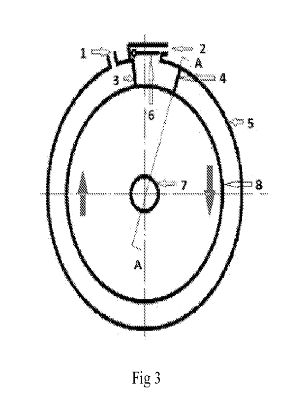
Fig 3&4 shows the simplified schematic of rotary engine,this engine has those
parts.
1 .outl et,always open
2.inlet,control by timer belt
3.throat,which stops 6(shutter) when it at the close position
4.piston,which fasten to 8(rotor) and fine matched to 5(engine body) &
8(rotor)
5.engine body
6.shutter,which has 2 positions:close position(throat position) & open
position(rest
position),droved by timer belt
7. shaft
8.rotor,which fine matched to the 5(engine body).when shutter is at close
position(throat
position)/inlet valve closed,the 8(rotor) & 6(shutter) & 4(piston) & 5(engine
body) form a closed
working chamber,combustion happens here,push the piston to drive rotor rotate
as the red arrows.
Brief description of the invention
The invention try to improve the fuel efficiency in two ways:
1,reduce the 4-stroke to 2-stroke;
2,ensure the force is perpendicular to the shaft always.
To understand how this engine works, we pick up one cycle during normal
working
Step 1: start from fig 5, at this time piston just passed shutter runaway
area, shutter ready to
close(means shutter turns to the throat position)õinlet valve opens and
compressed air fills in. after
shutter closed (at the throat position) fills the air with atomized fuel;
Step 2: As show in Fig 6,inlet valve close,combustion begin, fuel burns and
the pressure inside the
working chamber rises up,push piston and then drive rotor rotates,power stroke
begin.
Step 3: when power stroke is going to finish, the pressure inside working
chamber is not much
higher than the exhaust pressure, the piston moves to the position as fig 7,
at this time inlet valve
keep closed,shutter ready to open to let piston go through.
Step 4: show as fig 8, shutter is open and at it's rest position,inlet valve
keep closed,piston go
through the throat. and go to step 1.
Advantages of this invent
1.Simple but reliable.
2.The force is perpendicular on the rotary radius always,that means more power
output,and
finish one cycle in one rotation,that means more efficiency.
3.Easy to get bigger power, traditional engine always need to balance the
power with the radius
of crankshaft.
4.Working smoother than traditional engine, because no side force on chamber
wall, means
lower noise lower heat but longer lifetime.
The difficulties
The difficulty is sealing. There are two positions need to seal it well: L
between shutter and rotor at
the throat position; 2, between engine body with rotor and piston. Here are
some ways to resolve:
1.The layout of working chamber sealing. Fig 9 shows another layout,the shape
depend on
engineering.
2.It was difficult to make sure those moving parts fine match to stable parts
before,but we have
CNC now.
3.Choose different expand ratio materials for those parts, the smaller for
engine body and
shutter but the bigger for rotor and piston is an good idea. When engine heats
up rotor & piston
expands a little larger than engine body & shutter. After a short time running-
in, all the contact areas
will be very fine match with each other. As mentioned above this engine has no
side force, so it will
be fine match for a long time.
4.Carve patterns on the rotor/piston is anther good way for sealing. After a
short time running-
in,the carbon deposit,metal shavings and lubricating oil will accumulates in
this patterns,make it
like sealing.
SUBSTITUTE SHEET (RULE 26)
CA 03234075 2024- 4- 5

Representative Drawing
A single figure which represents the drawing illustrating the invention.
Administrative Status

For a clearer understanding of the status of the application/patent presented on this page, the site Disclaimer , as well as the definitions for Patent , Administrative Status , Maintenance Fee  and Payment History  should be consulted.

Administrative Status

Title Date
Forecasted Issue Date Unavailable
(86) PCT Filing Date 2021-10-15
(87) PCT Publication Date 2023-04-20
(85) National Entry 2024-04-05

Abandonment History

There is no abandonment history.

Maintenance Fee

Last Payment of $50.00 was received on 2024-04-05


 Upcoming maintenance fee amounts

Description Date Amount
Next Payment if small entity fee 2024-10-15 $50.00
Next Payment if standard fee 2024-10-15 $125.00

Note : If the full payment has not been received on or before the date indicated, a further fee may be required which may be one of the following

  • the reinstatement fee;
  • the late payment fee; or
  • additional fee to reverse deemed expiry.

Patent fees are adjusted on the 1st of January every year. The amounts above are the current amounts if received by December 31 of the current year.
Please refer to the CIPO Patent Fees web page to see all current fee amounts.

Payment History

Fee Type Anniversary Year Due Date Amount Paid Paid Date
Application Fee $225.00 2024-04-05
Maintenance Fee - Application - New Act 2 2023-10-16 $50.00 2024-04-05
Owners on Record

Note: Records showing the ownership history in alphabetical order.

Current Owners on Record
LI, LIANGUI
Past Owners on Record
None
Past Owners that do not appear in the "Owners on Record" listing will appear in other documentation within the application.
Documents

To view selected files, please enter reCAPTCHA code :


To view images, click a link in the Document Description column. To download the documents, select one or more checkboxes in the first column and then click the "Download Selected in PDF format (Zip Archive)" or the "Download Selected as Single PDF" button.

List of published and non-published patent-specific documents on the CPD .

If you have any difficulty accessing content, you can call the Client Service Centre at 1-866-997-1936 or send them an e-mail at CIPO Client Service Centre.


Document
Description 
Date
(yyyy-mm-dd) 
Number of pages   Size of Image (KB) 
Abstract 2024-04-07 1 19
Claims 2024-04-07 1 36
Drawings 2024-04-07 2 76
Description 2024-04-07 2 129
Representative Drawing 2024-04-07 1 20
National Entry Request 2024-04-05 2 51
Declaration 2024-04-05 1 29
Claims 2024-04-05 1 36
Patent Cooperation Treaty (PCT) 2024-04-05 1 59
Description 2024-04-05 2 129
Drawings 2024-04-05 2 76
Declaration 2024-04-05 1 61
International Search Report 2024-04-05 2 73
Correspondence 2024-04-05 2 44
National Entry Request 2024-04-05 8 226
Abstract 2024-04-05 1 19
Cover Page 2024-04-10 1 41