Note: Descriptions are shown in the official language in which they were submitted.
WO 2023/060299
PCT/AU2022/051218
- 1 -
SYSTEM AND METHOD/PROCESS FOR IN-FIELD MEASUREMENTS OF
PLANT CROPS
RELATED APPLICATION
[0001] The present patent application is related to Australian Provisional
Patent
Application No. 2021903273, filed 12 October 2021 in the name of Agriculture
Victoria
Services Pty Ltd and entitled "System and method/process for in-field
measurements of
plant crops", the originally filed specification of which is hereby
incorporated by reference
in its entirety.
TECHNICAL FIELD
[0002] The present disclosure relates to a system and a method/process for non-
destructive
in-field measurements of plant crops, e.g., for in-field crop phenotype
measurements/estimations (e.g., height and biomass/biovolume), e.g., including
for high-
throughput plant phenotyping (HTPP) and remote/non-contact
sensing/measurements.
BACKGROUND
[0003] Phenotypic characterization of crop genotypes is an essential yet
challenging aspect
of crop management and breeding research. Crop biomass and height may be
fundamental
morphological traits to estimate crop growth and selection of genotypes of
interest in a
breeding program. Crop biomass is associated with plant growth and
development, being
the basis of vigour and net primary productivity. Crop biomass is a measure of
the total
fresh weight (FW) or dry weight (DW) of organic matter per unit area, which
are measured
by destructively harvesting plants and weighing for FW, and oven drying and
weighing to
get DW. Plant height is the vertical distance from ground level to the upper
boundary of
the primary photosynthetic tissues, and conventionally measured in field using
rulers.
These manual and destnictive data collection methods are highly inefficient,
laborious,
operationally expensive and prone to manual error. Applicability of manual
methods are
limited to small field experimental trials and are not scalable and repeatable
for large field
CA 03234209 2024- 4- 8
WO 2023/060299
PCT/AU2022/051218
- 2 -
experimental trials.
[0004] Digital sensing technologies are rapidly advancing plant phenotyping
and speeding-
up breeding outcomes. However, existing sensors might not be fully applicable
and
suitable for agriculture research due to diversity in crop species and
specific need during
selection of preferred genotypes. Furthermore, existing digital sensor units
may be too
large, heavy and/or expensive for some applications, e.g., HTPP, and/or may
require post-
processing of too much data (e.g., a large number of images to accurately
construct depth
models, or large data output from 360-degree Light Detection And Ranging
devices
(LiDARs)), thus requiring enormous computational power.
[0005] It is desired to address or ameliorate one or more disadvantages or
limitations
associated with the prior art, or to at least provide a useful alternative.
SUMMARY
[0006] In accordance with the present invention, there is provided a
measurement system
100 including:
a. a sensor system 300 that includes:
i. a Light Detection And Ranging (LiDAR) module 302 with a laser
emitter 318 configured to generate measurement data representing
raw range measurements to measure heights of a crop 104 (of plants,
e.g., a plot or field with abutting plants in both horizontal
dimensions, including pasture crops), and
ii. a computing module 304, including:
at least one wireline/wired communications module
configured to communicate with the LiDAR module 302 for
the computing module 304 to acquire the measurement data
(e.g., including a USB module with a USB port, and/or a
general-purpose input/output module with GPIO port) from
the LiDAR module 302; and
at least one wireless communications module 326 (e.g., a
CA 03234209 2024- 4- 8
WO 2023/060299
PCT/AU2022/051218
- 3 -
wireless local area network (WLAN) module, a cellular
module, and/or a cellular Internet-of-Things (IoT) module)
configured for the computing module 304 to communicate
using a wireless connection/link 110 with a remote
computing system 106 (e.g., which can include a cloud-
computing server access via the Internet 108) that is
configured receive the acquired measurement data and to
determine/calculate/estimate phenotypic quantities of the
crop 104 based on (processed data representing) the
measured heights for the purpose of high-throughput plant
phenotyping (HTPP); and
b. a mobile/vehicle mount 102 configured to hold/support the sensor system
300 above the crop 104 and to direct the laser emitter 318 towards the crop
104.
[0007] The sensor system 300 may include at least one sensor case 500 that is
configured
to surround, enclose and encase electronic circuity portions of the LiDAR
module 302 and
the computing module 304 to seal off the enclosed circuity portions to
mitigate/stop
ingress of moisture/dust/dirt while the sensor system 300 is operating in a
field. The
sensor case 500 may include a plurality of portions (or parts/pieces/sides)
formed/manufactured of an additive/3D printing material (using an additive/3D
printer).
The plurality of portions may be mutually assembled/fastened by threaded
fasteners. The
sensor case 500 may include compressible/deformable seals/gaskets between
mutually
assembled ones of the portions, optionally wherein the mobile/vehicic mount
102 is
configured to hold/support the power case/housing such that laser emitter is
directed
towards the crop 104.
[0008] The sensor system 300 may include a power source 310. The power source
310
may include a battery 312 that powers the LiDAR module 302. The power source
310
may include a DC-to-DC converter 314, powered by the battery 312, that
provides a
different voltage from that powering the LiDAR module 302 to power the
computing
module 304. The power source 312 may include a power case/housing that
surrounds,
encloses and encases electronic circuity portions of the power source 310 to
seal off the
CA 03234209 2024- 4- 8
WO 2023/060299
PCT/AU2022/051218
- 4 -
enclosed circuity portions to mitigate/stop ingress of moisture/dust/dirt
while the power
source 310 is operating in afield. The mobile/vehicle mount 102 may be
configured to
hold/support the power case/housing such that the power source 310 is
electrically
connected/connectable to the LiDAR module 302 and the computing module 304.
[0009] The sensor system 300 may include a global navigation satellite system
(GNSS)
module 306 with a GNSS receiver 308 configured to simultaneously measure the
geolocation of the sensor system 300 while the LiDAR module 302 is measuring
the
heights. The computing module 304 may include at last one wirelinc/wired
communications module configured to communicate with the GNSS module 306 for
the
computing module 304 to receive the geolocation data (e.g., including a USB
module with
a USB port, and/or a general-purpose input/output module with GPIO port). The
sensor
case 500 may be configure to surround, enclose and encase electronic circuity
portions of
the GNSS module 306 to seal off the enclosed circuity portions to
mitigate/stop ingress of
moisture/dust/dirt while the sensor system 300 is operating in a field.
[00101 The sensor system 300 with the LiDAR module 302, the computing module
304,
the GNSS module 306 (with the GNSS receiver 308) and the sensor case 500 may
have a
weight of less than 1 kilogram (kg), or less than 550 grams (g), or between
350 and 500 g.
The LiDAR module 302 may have a weight of less than 200 g, the computing
module 304
may have a weight of less than 50 g, the GNSS module 306 (with the GNSS
receiver 308)
may have a weight of less than 100 g, and/or the sensor case 500 may have a
weight of less
than 200 g.
[0011] The LiDAR module 302 may include a LiDAR sensor 303 configured for one-
dimensional scanning (which is side-to-side scanning or "across-track"
scanning when in
use), optionally in a horizontal across-track scanning direction that is at
least partially, and
typically substantially, perpendicular to a horizontal along-track travel
direction of the
mobile/vehicle mount 102 (the "track" is the travel direction or route of the
mobile/vehicle
mount 102). The ID scanning LiDAR sensor 303 (i.e., configured for ID
scanning) may
include a solid-state LiDAR sensor. The solid-state LiDAR sensor may include a
micro-
electromechanical system (MEMS) chip or an optical phased array. The solid-
state
LiDAR sensor is configured to steer a laser beam from the laser emitter 318
along the
horizontal scanning direction (side-to-side or across-track when in use). By
steering the
CA 03234209 2024- 4- 8
WO 2023/060299
PCT/AU2022/051218
-; -
laser beam using solid-state components of the LiDAR sensor, which can be the
MEMS
chip or phased array, the solid-state LiDAR sensor may have no mechanical
moving parts
larger than elements of a MEMS chip, e.g., no mechanical moving parts with an
average
diameter larger than 0.1 mm. The 1D scanning may be over the horizontal across-
track
scanning distance that corresponds to a side-to-side or across-track field of
view (FoV) of
the LiDAR sensor, optionally wherein the across-track FoV is less than 90
degrees, or less
than 60 degrees, optionally wherein the LiDAR sensor has a front-to-back or
along-track
FoV that is substantially perpendicular to the across-track FoV and that is
substantially less
than the across-track FoV, optionally wherein the along-track FoV is less than
1 degree or
substantially 0.3 degrees. By scanning the laser beam over a limited
horizontal scanning
distance, corresponding to a FoV less than 90 or 60 degrees, the data output
from the
LiDAR module 302 may be substantially less than if a larger distance or area
were
scanned.
[0012] The computing module 304 (in its onboard memory) may include
credentials
(including a password and/or a subscriber identity module (SIM)) configured to
automatically connect to a wireless network 112 via the wireless
connection/link 110. The
wireless connection/link 110 may include a radio-frequency carrier.
[0013] The mount 102 may include a ground vehicle/mount with wheels configured
to roll
the sensor system 300 along ground/soil under the crop in a travel direction
of the mount
102 that is at least partially transverse to a horizontal scanning direction
of the laser emitter
318, optionally wherein the mount 102 is configured to hold/support the LiDAR
module
302 at a selected height above the ground/soil while the LiDAR module 302 is
measuring
the heights.
[0014] The measurement system 100 may include the remote computing system 106.
The
remote computing system 106 may include machine-readable memory ("server
memory")
and one or more microprocessors ("server microprocessors") connected to
perform
operations by executing server operational modules (-server modules") that
include data
processing modules (referred to as "high-level processing nodes") that include
any one or
more of:
a. a calibration module configured to determine calibrated range
measurements from the raw range measurements and a stored calibration
CA 03234209 2024- 4- 8
WO 2023/060299
PCT/AU2022/051218
- 6 -
model (representing calibration measurements and true calibration
distances);
b. a range-to-height conversion module configured to control the server
microprocessors to convert the (raw or calibrated) range measurements (r)
into crop height measurements (h);
c. a denoising module configured to mitigate spurious/noisy disturbances in
the crop height measurements (h) due to undulations of ground under the
crop 104 by performing a denoising process on the crop height
measurements (h), including:
i. filtering the crop height measurements (h) with a smoothing filter,
ii. removing ground-surface heights in the crop height measurements
(h) using a vertical threshold (e.g., Arth< 5 cm) to remove undulating
ground surface heights, and/or
iii. removing false peaks under a horizontal threshold (Hth) lengthwise
scan size of samples (e.g., Hth< 50 samples);
d. a segmentation module configured to automatically segment the crop height
measurements (h) into a plurality of mutually separate plot profiles
corresponding to respective mutually separate plots of the crop 104 along a
direction of travel of the mount 102;
e. a speed-compensation module configured to automatically compensate for
variable speed of movement of the sensor system 300 along a direction of
travel of the mount 102 by resampling the crop height measurements (h) to
a constant selected rate for each of the plurality of separate plot profiles;
f. an edge-compensation module configured to automatically remove or add
edges from/to the crop height measurements (11, H) corresponding to range
measurements from outer detector elements of the LiDAR module 302 by
automatically adjusting the height values of these edges;
g. optionally a geolocation module configured to automatically geolocate the
crop height measurements (h, H), based on geolocation data/tags from the
CA 03234209 2024- 4- 8
WO 2023/060299
PCT/AU2022/051218
- 7 -
GNSS module 306;
h. a phenotypic module configured to automatically control the remote
microprocessor to calculate/measure/estimate a phenotypic measurement
from the height measurements, optionally wherein the phenotypic
measurement includes a biovolume measurement, and the phenotypic
module includes a biovolume module configured to automatically control
the remote microprocessor to calculate/measure/estimate a crop biovolume
(BV) from the height measurements;
i. a master data repository configured to store the range measurements, the
crop height measurements, the phenotypic measurements, and/or
geolocation data; and
j. an output module configured to automatically output the phenotypic
measurements to machine-readable memory and/or to a user device for
display to a user.
[0015] In accordance with the present invention, there is provided a
measurement
method/process 200 that includes:
a. a sensor system automatically measuring heights of a crop 104 using
Light
Detection And Ranging (LiDAR) while being held/supported by a mount
102 moving over/across the crop 104 (202); and
b. the sensor system automatically wirelessly sending data representing the
corresponding measured heights to a remote computing system 106 (206)
for high-throughput plant phenotyping (1-1TPP).
[00161 The measurement method/process 200 includes:
a. the remote computing system automatically
detennining/calculating/estimating phenotypic quantities ("phenotypic
measurements") of the crop 104 based on the received data representing the
corresponding measured heights (208) for the purpose of HTPP; and
b. the remote computing system automatically outputting the phenotypic
measurements (210) to machine-readable memory (e.g., the master data
CA 03234209 2024- 4- 8
WO 2023/060299
PCT/AU2022/051218
- 8 -
repository) and/or to a user device for display to a user (e.g., a farmer or
scientist).
BRIEF DESCRIPTION OF THE DRAWINGS
[0017] Some embodiments of the present invention are hereinafter described, by
way of
example only, with reference to the accompanying drawings, in which:
a. FIG. 1 is a schematic diagram of a system ("measurement system-)
configured for making in-field measurements of field plant crops;
b. FIG. 2 is a flowchart of a method ("measurement method") of making in-
field measurements of field plant crops;
c. FIG. 3 is block diagram of a sensor system of the measurement system;
d. FIG. 4 is a photograph of electronic circuity portions of the sensor
system
inside a sensor case;
e. FIG. 5 is a perspective diagram of side parts for the sensor case of the
sensor system;
f. FIG. 6 is a photograph of a calibration apparatus of the measurement
system;
g. FIG. 7 is a diagram of a trajectory/path/pattern of the sensor system
over a
plurality of field plots with respective field plant crops;
h. FIG. 8 is a perspective photograph of the sensor system on a mobile
vehicle
mount;
i. FIG. 9 is a perspective photograph of the sensor system showing its
orientation/position on the mount;
j. FIG. 10 is a front-view photograph of the sensor system on the mount;
k. FIGs. 11 is a front-view diagram of LiDAR beam segments extending
downwards from the sensor system to the field crop;
1. FIG. 12 is a front-view diagram of the LiDAR beam
segments' geometry;
CA 03234209 2024- 4- 8
WO 2023/060299
PCT/AU2022/051218
- 9 -
m. FIG. 13 is a graph of height profile in meters (Y axis) versus LiDAR return
samples (X axis) of an example continuous height profile, measured by the
system, with spurious noise and false peaks;
n. FIG. 13A is an expanded portion of the graph marked with a rectangle in
FIG. 13 showing a false peak;
o. FIG. 14 is a graph of height profile in meters (Y axis) versus LiDAR return
samples (X axis) of a processed example continuous height profile showing
removal of noise, false peaks, and ground profile from the example
continuous height profile of FIG. 13 by segmentation and classification;
p. FIG. 14A is an expanded portion of the graph marked with a rectangle in
FIG. 14 showing removal of the false peak;
q. FIG. 15 is a graph of height profile in meters (Y axis) versus LiDAR return
samples (X axis) of a plurality of classified extracted plot profiles from the
continuous height profile of FIG. 14;
r. FIG. 16 is a graph of height profile in meters (Y axis) versus LiDAR
return
samples (X axis) of a plurality of resampled plot scans from the extracted
plot profiles of FIG. 15;
s. FIG. 17 is a front-view diagram of the LiDAR geometry for a plot of
medium-sized plants;
t. FIG. 18 is a top-view diagram of the LiDAR footprint on the plot of
medium-sized plants with a grid of LiDAR segments (left to right) and
LiDAR samples/scans (bottom to top);
u. FIG. 19 is a front-view diagram of the LiDAR beam segment geometry for
a plot of small-sized plants showing where pulses return from the group on
the left and right edges (edge segments);
v. FIG. 20 is a top-view diagram of the LiDAR footprint on the plot of
small-
sized plants with a grid of LiDAR segments (left to right) and LiDAR
samples/scans (bottom to top), showing removal of the edge segments;
w. FIG. 21 is a front-view diagram of the LiDAR beam segment geometry for
CA 03234209 2024- 4- 8
WO 2023/060299
PCT/AU2022/051218
- 10 -
a plot of tall-sized plants;
x. FIG. 22 is a top-view diagram of the LiDAR footprint on the plot of tall-
sized plants with a grid of LiDAR segments (left to right) and LiDAR
samples/scans (bottom to top), showing extrapolation of the edge segments;
y. FIG. 23 is a graph of an example model between sensor measured distances
in cm (X axis) and reference distances in cm (Y axis), with respective
measurements of eight sensor elements as dots, and fitted regression models
for the respective detector elements as lines;
z. FIGs. 24 to 26 are graphs of example sensor measurements (X axes) and
manual ground-truth (GT) measurements (Y axes) for example crops
measured at 100 DAS (circles) and 140 DAS (triangles), and corresponding
regression lines (dotted lines), wherein the measurements are of: GT (Y)
versus sensor-measured plant height in cm (X) in FIG. 24, GT dry biomass
in kg (Y) versus sensor-measured biovolume in cubic metres (X) in FIG.
25, and GT fresh biomass in kg (Y) versus sensor-measured biovolume in
cubic metres (X) in FIG. 26:
aa. FIGs. 27 to 29 are column graphs of frequencies (Y axes) of absolute error
measurements (X axes) in the example sensor measurements of FIGs. 24 to
26, wherein the absolute error measurements are in the example
measurements of: plant height (in cm) in FIG. 27, dry biomass (in kg) in
FIG. 28, and fresh biomass (in kg) in FIG. 29;
bb. FIGs. 30 to 32 are bar graphs of example phenotypic measurements (X
axes) for a plurality of different wheat genotypes (Y axes), measured at 100
DAS (solid colour columns) and 140 DAS (patterned columns), wherein the
phenotypic measurements are of: plant height (in cm) in FIG. 30, fresh
weight/biomass (kg) in FIG. 31, and dry weight/biomass (kg) in FIG. 32;
and
cc. FIGs. 33 to 36 are plots of measured field plant height in metres (Y axis)
versus ID distance along/across the plot in measurement bins which
correlate linearly to distance (X axis) for four respective example plots of
CA 03234209 2024- 4- 8
WO 2023/060299
PCT/AU2022/051218
- 11 -
ryegrass measured in a trial using both: (a) the measurement system
disclosed herein (shown in dashed lines) and (b) a commercially available
2D scanner ("LMS400") for comparison (shown in unbroken lines).
DETAILED DESCRIPTION
Overview
[0018] Described herein is a measurement system, a measurement method, and a
sensor
system that is Internet-of-Things (IoT)-enabled by way of wireless
communication with a
remote computing system (which can include a cloud-computing server access via
the
Internet) and global navigation satellite systems (GNSS), and that uses light
distance-and-
ranging (LiDAR) to provide non-destructive high-throughput in-field plant
phenotyping,
including crop height and biomass measurements, for crop monitoring (while
leaving the
crop alive in the field) and management for precision agricultural
applications. In
particular embodiments, the plant crop is a field crop plant and/or greenhouse
crop plant,
particularly a cereal crop, a pasture crop, a vegetable crop, an oil-seed
crop, or a Cannabis
crop. The field plant crop or greenhouse crop includes many plants that are
mutually
closely spaced in the field or plot or greenhouse
________________________________ e.g., grain-type or pasture crops such as
wheat, tall fescue, barley, ryegrass, lucerne (and/or other tall
cereal/pasture crops or short
cereal/pasture crops), field peas and lentils (and/or other vegetable crops),
oil-seed crops
(such as canola, safflower, sunflower, soybeans), or Cannabis ¨such that the
plants can be
described as being in a field or pasture or greenhouse, mutually abutting in
both horizontal
dimensions, which is in contrast to non-field crops, e.g., orchard crops like
fruit trees, that
are mutually spaced, e.g., to allow people and machinery to move between
mutually
adjacent trees.
[0019] The sensor system may be low in weight, low in cost, and/or have
relatively simple
data acquisition and processing, and seamless extraction of plant traits,
including crop
biomass and height. Implementations of the sensor system may be relative light
weight.
Implementations of the sensor system may provide rapid data collection in the
field of the
crop, including spatially-located (geolocated) crop height measurements,
injection of data
onto the remote computing system via a wireless Internet connection, and
automated data
CA 03234209 2024- 4- 8
WO 2023/060299
PCT/AU2022/051218
- 12 -
processing. Implementations of the sensor system described herein may provide
better
accuracy in phenotyping crop genotypes compared to ultrasonic systems,
including due to
a higher sampling rate, using of multiple stacked detectors, and/or a focused
field of view
(FoV). Implementations of the sensor system described herein may produce
significantly
less voluminous measurement data, allowing for improved communication with a
remote
computing system for easier cloud uploading and processing. The sensor system
may be
able to non-destructively estimate plant biomass and height using the
integrated ground-
based sensor with an end-to-end pipeline in data acquisition through to the
IoT-based cloud
uploading and processing. Moreover, high temporal resolution data provides the
opportunity to study dynamic crop responses to the environment to evaluate
genotype
performance.
[0020] In experimental testing of an implementation of the sensor system
described
hereinafter, crop fresh biomass, dry biomass and plant height estimated by the
sensor
system results had high correlations with comparison measurements (including
ground-
truth manual measurements or accurate reference LiDAR imaging measurements) in
a
wheat field trial and in a ryegrass field trial. In the context of precision
agriculture, plant
biomass and height are valuable traits for making informed management
decisions, and the
proximal sensor system is able to estimate these without damaging the in-
season crop. The
sensor system can be readily mounted on a tractor or boom-spray to collect
field
measurements. The adopted agronomic design of the small-scale field experiment
enables
direct transferability of the established biomass and height estimation models
to a
conventionally managed larger-scale farmer's field. Furthermore, the presented
method of
modelling biomass in wheat and ryegrass could be suitably extended for non-
destructive
in-season estimation of biomass in other field crops including vegetable,
grain and forage
crops.
System and Method
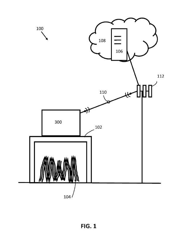
[0021] As shown in FIG. 1, described herein is a measurement system 100
including:
a. a sensor system 300;
b. a mobile/vehicle mount 102 configured to hold/support the sensor system
300 above a crop 104 (of field/pasture plants, e.g., a plot); and
CA 03234209 2024- 4- 8
WO 2023/060299
PCT/AU2022/051218
- 13 -
c. a remote computing system 106, e.g., which can include a cloud-computing
server accessed via the Internet 108, configured to communicate with the
sensor system 300 using at least one data communication protocol and
connection, e.g., a wireless connection/link 110 (which can include a radio-
frequency carrier) and a wireless network 112 (providing a wireless Internet
connection, e.g., via a cellular data network and/or via local area network
(LAN)), and including a master data repository configured to store the
measurement and geolocation data.
[0022] As shown in FIG. 2 and described hereinafter, the measurement system
100 is
configured to perform/execute a measurement method/process 200 ("method 200")
which
includes:
a. the sensor system 300 automatically measuring heights of the crop 104
while being held/supported by the mount 102 moving over/across the crop
104 (202);
b. the sensor system 300 automatically and wirelessly sending data
representing the corresponding measured heights to the remote computing
system 106 (206); and
c. the remote computing system 106 determining/calculating/estimating
phenotypic quantities ("phenotypic measurements") of the crop 104 based
on the data representing the corresponding measured heights and
geolocations (208) for the purpose of high-throughput phenotyping.
[0023] As shown in FIG. 2 and described hereinafter, the measurement method
200
includes:
a. the sensor system 300 automatically measuring/determining a geolocation
of each height measurement by simultaneously measuring the geolocation
of the sensor system 300 while measuring the heights (204);
b. the sensor system 300 automatically and wirelessly sending data
representing the corresponding measured geolocations to the remote
computing system 106 (206); and
CA 03234209 2024- 4- 8
WO 2023/060299
PCT/AU2022/051218
- 14 -
c. outputting the phenotypic measurements (210) to machine-readable
memory (e.g., the master data repository) and/or to a user device for display
to a user (e.g., a farmer or scientist)
Sensor System
[0024] As shown in FIG. 3; the sensor system 300 includes:
a. a LiDAR module 302, configured to make range measurements, thus
generating measurement data representing the range measurements, to
measure the heights of the crop 104¨the LiDAR module 302 includes a
LiDAR sensor 303;
b. a computing module 304, including a microprocessor 322, machine-
readable memory readable/writable by the microprocessor 322 (e.g., a
Raspberry Pi(TM) 4 computer), and at least one wireless communications
module 326 (e.g., including a microchip and/or antenna) configured for the
computing module 304 to communicate using the wireless connection 110
(wherein the wireless communications module 326 and its antenna are
configured to communicate according to a wireless data protocol, e.g., a
cellular protocol _______________________ including an Internet-of-Things
(IoT) protocol defined
by the ITU (e.g., LTE, 2G/3G/4G/5G/6G, NB IoT), a wireless local area
network (WLAN) protocol (e.g., WiFi, 2.4 GHz and 5.0 GHz IEEE
802.11ac), and/or a Bluetooth protocol (e.g., 5.0, BLE)); and
c. a GNSS module 306 with a GNSS receiver 308 configured to
simultaneously measure the geolocation of the sensor system 200 while the
LiDAR module 302 is measuring the heights (e.g., based on a GNSS logger,
e.g., based on a Navio (TM) unit from Emlid Ltd., Hong Kong).
[0025] By way of the LiDAR module 302, the sensor system 300 is configured for
non-
contact/remote sensing/measurement of the crop 104, thus mitigating/avoid
damage to the
crop 104 during the measurements, allowing for repeated/continuous
measurements
without damaging the crop 104.
[0026] As shown in FIG. 3, the sensor system 300 may also include a power
source 310.
The power source 310 may include a battery 312, e.g., a 12-volt battery, that
powers the
CA 03234209 2024- 4- 8
WO 2023/060299
PCT/AU2022/051218
- 15 -
LiDAR module 302. The power source 310 may include a DC-to-DC converter 314,
powered by the battery 312, that provides an output voltage connector 316 with
a different
voltage from that powering the LiDAR module 302, e.g., 5 volts, to power the
computing
module 304 and the GNSS module 306 with the GNSS receiver 308.
[0027] The LiDAR module 302 is configured to make the range measurements (also
referred to as "LiDAR measurements") substantially downwards from the LiDAR
module
302 to the crop 104 due to the mounting/positioning/orientation of the LiDAR
module 302
on the mount 102. The range measurements arc indicative of the crop height
measurements as described hereinafter. The LiDAR module 302 is configured to
specifically measure range in the selected direction (downwards) within a
required/predefined Field of View (FoV) of the LiDAR sensor 303.
[0028] The LiDAR sensor 303 is configured for one-dimensional scanning (which
is
across-track scanning when in use), which can be only one-dimensional (1D)
scanning
along the across-track direction (referred to as "a first horizontal
direction" or "horizontal
scanning direction") because scanning along the back-to-front direction
(referred to as -a
second horizontal direction' or "horizontal travel direction", which is at
least partially,
and/or substantially (which is typical), perpendicular to the first horizontal
direction) is
provided by movement of the mount 102. This raster-like scanning along the two
mutually
perpendicular horizontal directions generates the two-dimensional images. The
1D
scanning LiDAR sensor 303 (i.e., configured for 1D scanning) includes a solid-
state
LiDAR sensor. The solid-state LiDAR sensor may include a micro-
electromechanical
system (MEMS) chip or an optical phased array to steer a laser beam from the
LiDAR
sensor 303 along the first horizontal direction. By including solid-state
components of the
LiDAR sensor, which can be the MEMS chip or phased array, to steer the laser
beam, the
solid-state LiDAR sensor may thus have no mechanical moving parts larger than
elements
of the MEMS chip, e.g., the solid-state LiDAR sensor may thus have no
mechanical
moving parts larger than 0.1 mm average diameter. The LiDAR sensor 303 may
have a
relatively narrow across-track scanning distance (along the first horizontal
direction) to
scan only the crop's canopy profile. The across-track scanning distance may
correspond to
an across-track FoV of less than 90 degrees, less than 60 degrees, less than
50 degrees,
between 35 degrees and 60 degrees, or between 45 degrees and 50 degrees, e.g.,
CA 03234209 2024- 4- 8
WO 2023/060299
PCT/AU2022/051218
- 16 -
substantially 48 degrees. By using 1D scanning and the relatively narrow
across-track
scanning distance, the LiDAR sensor 303 may generate significantly less data
output and
processing overload compared to other LiDAR units, e.g., 360-degree LiDAR
scanners.
Using the 1D scanning may allow the LiDAR sensor 303 to be smaller, lighter
and/or
simpler that other LiDAR units, e.g., 360-degree LiDAR scanners, and/or may
allow it be
attached easily to any mount or vehicle, e.g., existing farm
equipment/vehicles (e.g., a
watering boom or a fertilizer boom), e.g., because it is small and not heavy
(and can be
moved/attached manually) and/or because it draws less power (and generates
less heat)
than an 3D imaging system. The LiDAR module 302 is configured to send pulsed
light in
the laser beam (from the light/laser emitter 318) down to the crop 104, and to
detect (in a
light receiver 320) the pulsed light reflected from the crop 104 within the
FoV. The
LiDAR module 302 is configured to measure the reflected pulses in a plurality
of discrete
beam segments 1102 (e.g., 4 to 16, e.g., 8) as shown in FIG. 11, wherein the
discrete beam
segments 1102 are arranged across the across-track scanning distance (and
along the first
horizontal direction), with each segment 1102 having a fractional FoV of the
across-track
FoV, which can be a substantially equal fraction each (e.g., 6 degrees each),
and each
segment 1102 corresponds to LiDAR detector element in the LiDAR sensor 303.
The
LiDAR sensor 303 may have an along-track FoV that is substantially
perpendicular to the
across-track FoV and that is substantially less than the across-track FoV,
e.g., the along-
track FoV may be of less than 1 degree, e.g., 0.3 degrees. The along-track FoV
is
substantially parallel to a direction of travel of the mount 102
through/along/over the crop
104, and the across-track FoV is thus substantially across the plot/portion of
the crop 104
under the mount 102. The LiDAR module 302 may have an across-track FoV of 0430
substantially 48 in the across-track (or -side-to-side") direction. The
plurality of LiDAR
detector elements, e.g., 8, may be mutually stacked. Each of the stacked
detector elements
may have a mutually equal horizontal FoV, e.g., 0 = 6 degrees, covering the
plots along
the widthwise direction, AB, as shown in FIGs. 11 and 12. As mentioned
hereinbefore, the
LiDAR sensor 303 may thus be described as configured for 1D scanning (in the
across-
track direction) because scanning in the along-track direction is provided by
movement of
the mount 102. The LiDAR module 302 may be based on a sensor from Leddar Tech
(TM), Quebec, Canada.
CA 03234209 2024- 4- 8
WO 2023/060299
PCT/AU2022/051218
- 17 -
[0029] The LiDAR sensor 303 includes the laser emitter 318 which may be
configured to
operate over at least one near-infrared (NIR) wavelength (e.g., between 700 nm
and 3,000
nm, or between 700 nm and 2,500 nm, or between 700 nm and 1,400 nm, or
substantially
905 nm). The laser emitter 318 may have at least a Class 1 eye safety rating,
e.g.,
according to IEC 60825-1:2014. The laser emitter 318 and the corresponding
light
receiver 320 are powered by the power source 310, e.g., by the battery 312 at
a voltage
supplied by the battery 312 (not requiring the DC-DC converter 314) which may
be 12V
0.6 DC. The laser emitter 318 and the light receiver 320 of the LiDAR module
302 are
mounted/directed substantially downward to face the crop 104 under the mount
102 to
direct the laser emitter 318 towards the crop 104. The laser emitter 318 and
light receiver
320 both face down when mounted to the mount 102, and thus the LiDAR module
302
may be referred to as having a nadir orientation (i.e., looking down). The
laser emitter 318
and light receiver 320 may be mutually separated as shown in FIG. 3, or may
substantially
overlap, so long as they have a nadir orientation. The LiDAR module 302 may
have a
power consumption from the power source 310 of between 0.5 and 10 watts (W),
e.g.,
between 1 and 3 W, e.g., substantially 2 W. The LiDAR module 302 includes a
carrier
board (printed circuit board) that hosts an electrical and communication
interface 323 of
the LiDAR module 302, which includes a plurality of communication interfaces,
e.g., SPI
and/or USB-CAN-serial (UART/RS-485). The LiDAR module 302 may be configured to
have a programmable/selectable data refresh rate, measurement accumulation,
and/or a
sensitivity peak, and the LiDAR sensor 303 may be tuned based on the type of
the target
vegetation in the crop 104.
[0030] The mount 102 is configured to hold/support the sensor system 300 above
a crop
104, and to direct the beam of the LiDAR module 302 substantially downwards
towards
the crop 104, thus holding/supporting the sensor system 300 in a
location/position/orientation such that it measures the distance between its
LiDAR module
302 (on the mount 102) and the crop 104, at least a top layer/canopy of the
crop 104. As
described hereinafter, the measurement system 100 is configured to measure the
height of
the crop 104 based on a difference between the height of the LiDAR module 302,
which is
referred to as its -mounted height' (i.e., the selected height of LiDAR module
302, and
thus the LiDAR sensor 303, above the ground/soil, marked "D" in FIG. 12) and
the
CA 03234209 2024- 4- 8
WO 2023/060299
PCT/AU2022/051218
- 18 -
measured distance between the LiDAR module 302 and the crop canopy. The laser
emitter
318 and the light receiver 320 are oriented substantially downward such that
the crop 104
substantially fills the FoV. The mobile/vehicle mount 102 (or "field mount" or
"rover")
may include wheels configured to roll the sensor system 300 along the
ground/soil (e.g.,
substantially parallel to the ground) under the crop 104. The mount 102 with
the wheels
may include a manual push-type vehicle or a motor, thus forming a motorised
vehicle/mount, which may include a tractor or a spray boom, a watering boom or
a
fertilizer boom. The mount 102, its motor (if present), its control/steering
system, and its
wheels are configured to move the sensor system in the selected horizontal
travel direction
(e.g., along a lengthwise direction 802 shown in FIG. 8) of the mount that is
at least
partially transverse to the across-track horizontal scanning direction (the
first horizontal
direction) of the laser emitter 318. The mount 102 may include a ground
vehicle/mount
with the wheels, and may have a wheelbase or width of at least 1.25 m to
enable traversing
the sensor system 300 along the lengthwise direction 802 of the crop as shown
in FIG. 8.
The mounted height may be between 1 m and 10 iii, or between 1.2 m and 3 iii,
or
substantially 1.8 m. Having the mobile/vehicle mount 102 in the form of the
ground
vehicle/mount with wheels may be preferable in some applications, e.g., where
aerial
vehicles cannot operate with sufficient stability or for sufficient durations.
In
implementations, the mobile/vehicle mount 102 may include the wheeled
vehicle/mount in
the form of a side-by-side vehicle ("Sx_S" or "SSV"), an unmanned ground
vehicle (which
has a space below the vehicle, as used agriculture research fields), or a
mower (configured
to mow the field crop). The mobile/vehicle mount 102 may include a mounting
system or
attachment system that is configured to hold/support the sensor system 300
onto the
wheeled vehicle/mount, e.g., including at least one bracket and at least one
fastener,
including manually operable brackets/fasteners such that the sensor system 300
can be
manually attached to the wheeled vehicle/mount in its held/supported
location/position/orientation, allowing the sensor system 300 to measure the
crop heights;
and such that the sensor system 300 can be manually detached/removed from the
wheeled
vehicle/mount after the measuring¨being able to simply attach and operate the
sensor
system 300 demonstrates its modularity and ease of use.
[0031] The computing module 304 is configured to provide a sensor driver unit.
The
CA 03234209 2024- 4- 8
WO 2023/060299
PCT/AU2022/051218
- 19 -
computing module 304 may include single-board computer (SBC), e.g., a
Raspberry Pi 4
4GB Model B. The computing module 304 may have a compact size, e.g., as small
as (or
smaller than) the size of a credit card (e.g., a width and a height each less
than 150 mm,
and a depth less than 15 mm). The microprocessor 322 ("onboard
microprocessor") may
provide relatively decent processing power, e.g., at least substantially
equivalent to a
1.5 GHz quad-core Cortex-A72 (ARM v8) 64-bit System-on-Chip (SoC). The memory
may include at least 4 GB of onboard memory 324, including synchronous dynamic
random-access memory (SDRAM) storage (e.g., LPDDR4-3200). The computing module
304 may include wireline/wired communications modules configured for the
computing
module 304 to communicate with the LiDAR module 302 and the GNSS module 306 to
acquire/receive the measurement data and the geolocation data respectively,
e.g., via USB
with the wireline/wired communications modules including a USB module and USB
port
(e.g., including USB 3.0 ports, and USB 2.0 ports), and/or via a (40-pin)
general-purpose
input/output (GPIO) header/port with the wireline/wired communications modules
including a GPIO module and GPIO port. The memory may include removable memory
328 for loading an operating system and data storage, e.g., a Secure Digital
card and an SD
card slot (e.g., micro-SD). The operating system may be a Linux-based
operating system,
e.g., Raspbian Buster (TM). The memory includes an onboard data storage
system. The
memory includes one or more operational modules configured to be executed by
the
operating system, and configured to: (i) acquire the geolocation and
measurement data
from the GN SS module 306 and the LiDAR module 302, (ii) optionally process
the
acquired data onboard the computing module 304 to generate processed
measurement/geolocation data respectively, and (iii) upload the acquired
and/or processed
measurement/geolocation data to the remote computing system 106, which can
include a
cloud-computing server access via the Internet 108. The operational modules
may be
compiled from source files written in C++ and/or Python. For a 32 GB internal
memory
card, 6 GB may be invested in system files, packages, and the operational
modules, leaving
about 26 GB storage of the measurement data and geolocation data. For a data
rate of
about 400 Kbytes/minute, an example onboard data storage system could last for
up to
approximately 50 days in a continuous mode of operation, without cloud
uploading. If the
data are more frequently uploaded to the remote computing system 106 in the
"cloud", the
onboard data storage space is automatically cleaned up by the computing module
304, thus
CA 03234209 2024- 4- 8
WO 2023/060299
PCT/AU2022/051218
- 20 -
providing unlimited practical storage. The computing module 304 may be powered
by the
power source 310, including by the output voltage connector 316, e.g., at 5V
DC via a
USB-C connector or GPIO header of the computing module 304. The computing
module
304 may require relatively low power, e.g., less than 3 Amps at 5 Volts, i.e.,
less than 15
Watts.
[0032] The GNSS module 306 is a form of a global navigation system receiver
module
configured for geolocating/tagging the LiDAR measurements with their
respective
gcolocations, e.g., as data in positioning logs. Thc GNSS module 306 may
include a
GNSS receiver 308 (e.g., from Emlid Ltd., Hong Kong). The GNSS module 306 may
be
configured to support GPS, GLONASS, Beidou, Galileo, and/or SBAS satellite
constellation systems. The GNSS module 306 may be relatively low cost and
relatively
reliable compared to other commercial-grade positioning sensing systems. As
shown in
FIG. 3, the GNSS module 306 may include: a (dual) inertial measurement unit
(IMU) to
improve/correct the geolocation measurements; an RC input/output co-processor
332; a
barometer chip 334 to improve/correct the geolocation measurements; and a GNSS
receiver chip 336 to communicate with and receive data from the GNSS receiver
308.
[0033] Once the sensor system 300 is powered on, e g , manually, the operating
system
and the operational modules are configured to automatically connect the sensor
system 300
to the wireless network 112 via the predefined wireless connection 110 (e.g.,
WiFi, etc.)
available in the field, to connect with the master data repository of the
remote computing
system 106 that is configured to store the range and geolocation data. The
memory may
include credentials (including a password and/or a subscriber identity module
(SIM))
which the operational modules use to automatically connect to the wireless
network 112,
e.g., a password-protected hotspot or cellular network. Alternatively, in the
absence of a
nearby/available wireless network 112, the sensor system 300 enters in a non-
networked
mode in which the acquired measurement and geolocation data are saved onto the
computing module's memory and uploaded to the remote computing system 106 once
the
wireless connection 110 has been established, e.g., by later logging onto the
password-
protected hotspot. Once the acquired data have been uploaded to the remote
computing
system 106, the operational modules are configured to compress a local copy of
the
acquired data in an archive in the master data repository for safe-keeping,
while older data
CA 03234209 2024- 4- 8
WO 2023/060299
PCT/AU2022/051218
-21 -
points are automatically deleted as the memory of the computing module fills
to free up
system space.
[0034] Once the sensor system 300 is powered ON, the LiDAR module 302 and the
GN SS
module 306 may require less than 60 seconds, e.g., around 20 seconds, to
initialize, load
their required packages, and establish their respective data connections with
the computing
module 304.
[0035] The sensor system 300 can include an indicator (which can be a visual
indicator,
e.g., an LED; mounted to/on an enclosure of the sensor system 300), driven by
the
computing module 304 (e.g., connected to a physical JO pin of the computing
module
304), in which one of the operational modules is configured to indicate a
status of the
sensor system 300 to the user. The status (or "state") of the sensor system
300 is recorded
and updated in the memory by the operational modules. The status can include:
INITIALIZATION, after the sensor system 300 has been powered on, but before it
is ready
to make the measurements (during which the indicator can show a steady solid
signal, e.g.,
driven by a HIGH signal on the connected JO pin); READY (or -paused"), after
the
initialization, when the LiDAR module 302 and the GNSS module 306 are ready to
commence data acquisition but have not commenced (during which the indicator
can flash
rapidly, e.g., at a frequency of around 20 Hz, e.g., driven by a modulated
signal on the
connected JO pin); and ACQUISITION (or "active"), after the READY state,
during which
the LiDAR module 302 and the GNSS module 306 acquire the height and
geolocation data
(during which the indicator can show a steady solid signal, e.g., driven by a
HIGH signal
on the connected 10 pin). The sensor system 300 is configured to transition
between the
READY and ACQUISITION states multiple times. The sensor system 300 can include
at
least one manual control element, including a switch and/or button (e.g.,
active-low with
internal pull-up resistance), that, when manually activated, generating
signals ("trigger
signals") for the sensor system 300 to transition between the states. Critical
settings for the
GNSS module 306 and the LiDAR module 302, e.g., sampling frequency, signal
strength,
accumulation rate, and time tag format, are predefined as default parameters
for ease of in-
field operation.
[0036] The power source 310 may include voltage regulator circuitry that is
configured to
provide a steady and/or filtered DC output power, e.g., a 12 V constant
output, for the
CA 03234209 2024- 4- 8
WO 2023/060299
PCT/AU2022/051218
- 22 -
LiDAR module 302. The power source 310 may provide a step-down 5 V output to
power the computing module 304 and the GNSS module 306 in the form of the DC-
DC
converter 314. The power source 310 may provide total current consumption
rated
between 500 mA and 1,000 mA, e.g., around 800 mA, in the regular mode of
operation to
power the LiDAR 302, the computing module 304 and the GNSS module 306. The
sensor
system 300 may be configured to operate for up to 3 hours with the battery 312
in the form
of a portable 2500 mAh battery. The battery 312 can be swapped manually to
extend the
in-field operational time.
[0037] As shown in FIG. 3, the LiDAR module 302 is communicatively connected
to the
computing module 304 by a standard-defined interface, e.g., using a USB port
on the
computing module 304 and USB-CAN-serial communication. The GNSS module 306
(with the GNSS receiver 308) is communicatively connected to the computing
module 304
by a standard-defined interface, e.g., via a GPIO header/port of the computing
module 304.
Inclusion of the standard-defined interfaces in the sensor system 300 allows
easy
replacement of any one of the three modules 302,304,306 if required, e.g., due
to damage
during in-field use.
Sensor case
[0038] As shown in FIG. 4, the sensor system 300 includes at least one sensor
case 500
that is configured to surround, enclose and encase electronic circuity
portions of the
LiDAR module 302, the computing module 304 and the GNSS module 306¨thus the
LiDAR module 302, the computing module 304 and the GNSS module 306 may be
described as "integrated" together in the case 500. The sensor case 500 may
include the
power source 310, or alternatively, the power source 310 may include its own
power
case/housing that surrounds, encloses and encases electronic circuity portions
power
source 310. The sensor case 500 and the power case surround and seal off the
enclosed
circuity portions to mitigate/stop the ingress of moisture/dust/dirt while the
sensor system
300/power source 310 is operating in the field. As shown in FIG. 4, portions
of the
LiDAR module 302 may extend from the sensor case 500, e.g., the light receiver
320,
and/or an electrical connection to the power source 310. The manual control
element and
the indicator may be mounted on/to the sensor case 500 to provide convenient
manual
access, e.g., on a top or side of the case 500. The sensor case 500 (or
"enclosure") may be
CA 03234209 2024- 4- 8
WO 2023/060299
PCT/AU2022/051218
- 23 -
formed/manufactured of an additive/3D printing material, using an
additive/three-
dimensional (3D) printer (e.g., from Geldermalsen, The Netherlands). The
additive/3D
printing material may include a polymer material, which can be polymer
filament, e.g.,
acrylonitrile butadiene styrene (ABS) plastic filament (from Geldermalsen, The
Netherlands). As shown in FIG. 5, the sensor case 500 may include a plurality
of
portions/parts/pieces/sides, substantially forming a rectangular prism, each
formed/manufactured of the additive/3D printing material, including: a left
piece 502, a
back piece 504, a right piece 506, a bottom piece 508, a front piece 510 and a
top piece
512. Each of the plurality of pieces may be manufactured/printed separately.
The plurality
of pieces may be 3D printed, together, lying flat on the build plate, which
may allow for
stronger cross-sectional adhesion between the layered threads of the filament
compared to
printing the portions vertically, producing stronger printed pieces. After
manufacture/printing, the plurality of pieces may be mutually
assembled/fastened using
threaded fasteners (screws or bolts), e.g., M3 bolts. The sensor case 500 may
include
compressible/deformable seals/gaskets between mutually assembled ones of the
portions,
e.g., polymer rings, or "0" rings. The primary parameters for the 3D printer
configured to
manufacture/print the pieces may include one or more of: Layer Height of
substantially
0.1 m; Wall thickness of substantially 1.2 m; Infill Density of substantially
100%; Infill
Pattern of substantially Cubic; Printing Temperature of substantially 245 C;
Build Plate
Temperature of substantially 85 C; Print Speed of substantially 25 mm/s; and
Cooling Fan
speed of substantially 20 %.
[0039] The sensor system 300 with the LiDAR module 302, the computing module
304,
the GNSS module 306 and the sensor case 500 may have a weight of less than 1
kilograms
(kg), or less than 550 grams (g), which is relatively light-weight compared to
other digital
sensing technologies. The LiDAR module 302 may have a weight of less than 200
g, the
computing module 304 may have a weight of less than 50 g, the GNSS module 306
(with
the GNSS receiver 308) may have a weight of less than 100 g, and/or the sensor
case 500
may have a weight of less than 200 g. In implementations, the total weight of
the sensor
system 300 (including the LiDAR module 302, the computing module 304, the GNSS
module 306 and the sensor case 500, but not the power source 310) was within
the range
350 to 500 g, e.g., approximately 400 g. Approximate weights of example
implemented
CA 03234209 2024- 4- 8
WO 2023/060299
PCT/AU2022/051218
- 24 -
components described herein were as follows: the computing module 304 with the
Raspberry Pi (TM) was 46 g, the Navio (TM) unit was 23 g, the Leddar Tech (TM)
LiDAR
module was 144 g, the 3D print enclosure was 118 g, and other elements of an
example
sensor system (including wire, the GNSS receiver, the LED switch) were 67 g;
thus the
total weight of the example sensor system with the power source 310 was 398 g
(or
substantially 400 g).
[0040] The mount 102 is configured to hold/support the sensor system 300
(including the
power sourcc 310) on itself, e.g., by way of fastcncrs (such as straps/clips)
and a platform
(e.g., a mesh), as shown in FIGs. 8 and 9. The mount 102 is configured to the
sensor case
500 and the power case/housing mutually adjacent on the platform, e.g., as
shown in FIGs.
8 and 9, such that: (i) the laser emitter 318 is directed towards the crop
104; and (ii) the
power source 310 is electrically connectable to, or connected to when in
use/operation, the
LiDAR module 302 and the computing module 304.
Remote Computing System
[0041] The remote computing system 106 (which may be referred to as a "remote
server")
includes machine-readable memory ("server memory") and one or more
microprocessors
("server microprocessors") connected to perform operations by executing server
operational modules ("server modules") in the server memory. The server
modules may
include data processing modules referred to as "high-level processing nodes"
that are
configured to control the server microprocessors to provide high-level
functions on the
data send from the sensor system 300. The server modules may be configured to
execute
automatically and immediately when new acquired data is sent from the sensor
system 300
to the remote computing system 106. These high-level processing nodes may be
provided
in the remote computing system 106 instead of the computing module 304 because
the
server microprocessors may have substantially more processing power than the
onboard
microprocessor 322 and/or to mitigate power drain and overheating of the
onboard
microprocessor 322 and memory. The high-level processing nodes (of the server
modules)
may be configured to automatically analyse/process the measurement and
geolocation data
on receipt. The high-level processing nodes may be based on source code, e.g.,
written in
Python 3.7.8; and may use available source packages, including os, fnmatch,
matplotlib,
numpy, skimage, and opencv2. The high-level processing nodes may include: a
range-to-
CA 03234209 2024- 4- 8
WO 2023/060299
PCT/AU2022/051218
- 25 -
height conversion module; a denoising module; a segmentation module; a speed-
compensation module; an edge-compensation module; a geolocation module; a
phenotypic
module, which can include a biovolume module; and an output module.
Calibration
[0042] The measurement system 100 may include a calibration apparatus 600, and
the
onboard memory may include calibration data generated from (i.e., empirical
calibration)
of the LiDAR module 302 using the calibration apparatus 600. As shown in FIG.
6, the
calibration apparatus 600 includes: a plurality of legs (e.g., a tripod 602)
for holding the
sensor system 300 above a hard, flat area/surface 606 (which provides a
calibration
area/reflector bigger than the minimum FoV of the LiDAR module 302); an
extensible
portion (e.g., an arm 604) configured to adjust a "true" distance of the
sensor system 300
from the flat area/surface 606; and an coupling/mount 608 to hold the hold the
sensor
system 300 on/to the calibration apparatus 600 with its laser emitted oriented
towards the
area/surface 606. The measurement method 200 includes a calibration process in
which a
plurality of true calibration distances/heights (of a calibration point on the
sensor system
300 above the area/surface 606) are selected using the calibration apparatus
600 (e.g.,
manually or automatically with a motorised calibration apparatus 600), and
optical
calibration measurements (from the LiDAR module 302) are recorded and combined
with
the respective true calibration distances/heights to generate/record a
calibration model that
relates the LiDAR measurements (inputs) to the true distances/heights
(output). The
calibration process may include making the LiDAR measurements, e.g., for at
least 5
seconds at each distance, and/or using at least nine (9) calibration heights
specified, e.g.,
ranging from 40 cm to 265 cm in steps of approximately 30 cm. The calibration
process
may be performed for the plurality of detectors in the LiDAR module 302, e.g.,
9
calibration points measured for each detector, e.g., for 8 detectors there may
be 72 readings
forming the calibration model. The calibration model is stored as calibration
data in the
server memory, and the server modules include a calibration module that
controls the
server microprocessor to access the calibration model to determine calibrated
range
measurements (also referred to as "corrected" or "tuned" range measurements)
from the
LiDAR distance measurements (also referred to as the "raw" LiDAR
measurements), and
thus to provide precise distance profiles automatically, as described
hereinafter.
CA 03234209 2024- 4- 8
WO 2023/060299
PCT/AU2022/051218
- 26 -
Data Acquisition
[0043] During the data acquisition stage/state (which may be referred to as a
"scanning
mission"), including the simultaneous measurement processes 202 and 204 of the
measurement method, the sensor system 300 is moved by the mount 102 in a
pattern 702
transverse to the crop, e.g., as shown in FIG. 7. The pattern 702 may include
a sinuous
traverse path/trajectory, alternating in direction between mutually adjacent
parallel part
portions, to cover each row in an individual range, followed by the next range
in a reverse
direction. This pattern 702 may enable least movement of the mount 102 or the
equivalent
time in data acquisition.
[0044] The LiDAR module 302 and the computing module 304 may be configured to
record the LiDAR measurement data ("data scan") continuously throughout the
"measure
crop height" process 202 at a preselected scan rate, e.g., 10 Hz to 120 Hz,
e.g., 50 Hz to 70
Hz, e.g., substantially 60 Hz. The LiDAR module 302 may be configured to
record the
raw range measurements ("r") for each LiDAR detector, e.g., in a CSV format,
and the
operational modules of the computing module 304 are configured to control the
computing
module 304 to send the raw range measurements ("r") to the remote computing
system 106
as soon as possible after the scans, as described hereinbefore.
[0045] The calibration module controls the server microprocessor to access the
calibration
model to determine calibrated range measurements (also referred to as
"corrected" or
"tuned" height/range measurements) from the raw LiDAR distance measurements
and the
stored calibration model.
100461 The range-to-height conversion module is configured to control the
server
microprocessors to convert the calibrated range measurements (r) into crop
height
measurements (h) using a conversion process represented by trigonometric
calculations set
out in Equations (1) to (4) hereinafter, where, as shown in FIG. 12, D is the
mounting
height of the LiDAR detectors above the ground (which is defined by the mount
102 and
position of the sensor system 300 thereon), r is the raw range measurements
collected for a
detector, a and f3 are the orientation angles for a detector element from the
vertical axis
(SH) to the detector's FoV edge and center respectively (e.g.,
predefined/measured during
the calibration process), 0 is the predefined width of each detector element,
Ã13 is the total
FoV, n is the number of detector elements, and w is the width traced by a
detector with a
CA 03234209 2024- 4- 8
WO 2023/060299
PCT/AU2022/051218
- 27 -
FoV of 0 at an angle of f3 from vertical axis on the height (h):
h = D ¨ r. cos(p) (1)
(2)
0 = (.1)/ri (3)
w = r. cos 13 [tan a ¨ tan(a + 0)1 (4)
[0047] In the remote computing system, D, 0 and cri are stored as parameters
in the server
memory, whereas the variables r, a, 13, h, and w arc
received/generated/stored/accessed as
respective array vectors R, A, B, H, and W., e.g., the array vector H = [hi,
h2,... hid for
height.
[0048] The LiDAR scan measurements may be collected continuously over the
plots along
the transects (e.g., as shown in FIG. 7), in which case the height
measurements (h) may
include spurious or noisy disturbances during the data acquisition due to
undulations in the
ground surface. The denoising module is configured to mitigate the spurious or
noisy
disturbances in the height measurements (h) due to the undulations by
performing a
denoising process on the calculated crop height measurements (h), including
filtering the
calculated crop height measurements (h) with a smoothing filter, e.g., using a
Savitzky-
Golay filter; however, certain disturbances due to these undulations may
remain in the
form of false peaks 1302 near the edges of the plots, e.g., as shown in FIG.
13A. To
remove/reduce these false peaks 1302, first, the denoising module is
configured to cause
the remote microprocessor to classify ground surface measurements in the
height
measurements (h) and to mask off ground-surface height in the height
measurements (h)
using a vertical threshold (e.g., Vth < 5 cm) to remove the undulating ground
surface.
Second, the remote modules are configured to use a horizontal (Hih) threshold
criterion to
remove any remaining false peaks 1302 (also referred to as "continuous peak
segments")
under a threshold (Hth) lengthwise scan size of samples (e.g., Hai< 50
samples). As the
scan size or scan profile for the plots (e.g., 5 m long) is generally
significantly greater than
the size of false peaks 1302, the Hui provides a simple and effective basis to
eliminate any
slight undulations in the signal profile. An example of a remoted false peak
1402 I shown
in FIG. 14B.
[0049] The segmentation module is configured to automatically segment the
height
measurements (h) into mutually separate plot profiles corresponding to
mutually separate
CA 03234209 2024- 4- 8
WO 2023/060299
PCT/AU2022/051218
- 28 -
plots of the crop 104 along a direction of travel of the mount 102 (along the
direction of
the scan) into a plurality of extracted plot profiles that can be overlapped
as shown in FIG.
15.
[0050] The speed-compensation module is configured to automatically compensate
for
variable speed of movement of the mount 102, and thus the sensor system 300
along a
direction of travel of the mount 102 along the pattern 702. Even if the mount
102 traverses
at a near-constant speed (e.g., 1.4 m/s), maintaining a uniform speed
throughout a long
scan duration may impractical in field conditions. A lack of the uniform speed
leads to
mutually variable/unequal lengths 1502 of the number of measurements made for
mutually
different plots, e.g., as shown in FIG. 15. As the data are collected at a
constant rate from
the LiDAR module 302 (e.g., 60 Hz), a greater number of samples is captured
when the
mount speed is slower, and vice versa when the mount speed is faster. In an
example, the
number of samples for all the plots may range between 210 and 400, as shown in
FIG. 15.
To adjust for this discrepancy in sample numbers, the lengthwise acquisition
of the
samples may be resampled at/to a constant selected rate, e.g., m = 100 samples
per plot of
m in length, as shown in FIG. 16, thus the array vector H is acquired m times
or the
resampling frequency for each plot, forming am xn matrix, represented by Hplot
in
Equation (5).
1111
Hpiot = =(5)
hmi hmniITIXil
[0051] The edge-compensation module is configured to automatically remove or
add
edges from/to the scans, i.e., from the height measurements (h or Hoot),
corresponding to
range measurements from outer detector elements of the LiDAR module 302 by
automatically adjusting the height values of these edges. As the detector
elements are
stacked at different angles (a, (3) from the nadir, the widthwise/side-to-side
footprint (w)
increases progressively away from the nadir and reduces with the height (h) of
the crop
(per Equation 4), and as shown in FIGs. 11 and 12. For an optimum medium-sized
plot,
the FoV of the sensor covers the entire width 1802 of the crop plot (e.g., as
shown in FIGs.
17 and 18). However, a short-sized plot is farther from the sensor, so the FoV
covers
beyond the width 2002 of the plot (e.g., as shown in FIGs. 19 and 20), so ones
of the beam
CA 03234209 2024- 4- 8
WO 2023/060299
PCT/AU2022/051218
- 29 -
segments 1102 on the edges 2004 are automatically detected and removed by the
edge-
compensation module. Inversely, tall-sized plots are closer to the sensor, so
the FoV
covers less than a full width of the plot (e.g., as shown in FIGs. 21 and 22),
thus the edge-
compensation module extrapolates to account for the missed plants on the edge
of the
plots: a spatial resampling in the widthwise direction 2202 (to insert missing
heights along
the edges 2204) is applied by the remote microprocessor, controlled by the
edge-
compensation module, to adjust for this mismatch. The dimension of the Hplot
matrix
remains unchanged in this step, but the internal values are revised.
[0052] The geolocation module is configured to automatically geolocate the
height
measurements, which may be in the form of the Hoot matrix, based on the
geolocation
data/tags from the GNSS module 306. The Hplot represents a mathematical matrix
formulation of the collected height profile for each plot. The segmented Hplot
matrices may
be geolocated using the corresponding tags collected through the onboard GNSS
module
306. The sensor system 300 uses the GNSS module 306 to synchronise its
internal clock
with GNSS time. The remote microprocessor receives the GNSS timestamps in the
sent
data from the sensor system 300, and uses the GNSS timestamps to match the
geolocation
measurements with the height measurements using timestamps in the raw height
data (r).
The remote modules are configured to control the remote microprocessor to
match these
measurements to geolocate/register the segmented plot matrix Hplot, thus
generating a
geolocated Hit.
[0053] The phenotypic module is configured to automatically control the remote
microprocessor to calculate/measure/estimate a phenotypic measurement from the
height
measurements. The phenotypic measurement may include a biovolume measurement,
and
the phenotypic module include a biovolume module that is configured to
automatically
control the remote microprocessor to calculate/measure/estimate a crop
biovolume (BV)
from the height measurements. The geolocated Hplot for individual plots
enables
geospatial analysis to summarize average height and other statistical measures
such as
volume of the crop, termed as BioVolume (BV). The biovolume module is
configured to
automatically calculate the average height (havg) of each plot according to
Equation (6),
where, hm,, is a specific element of the Hoot matrix at 'nth row and nth
column, d
corresponds to the detector element, n is the total number of detectors (e.g.,
n=8), s
CA 03234209 2024- 4- 8
WO 2023/060299
PCT/AU2022/051218
- 30 -
represents the sample, and m represents the total number of samples per-plot
after
resampling (e.g., m=100):
s=m d=n
hay g ¨ 1
kno, (6)
m X n
s=1 d=1
[0054] The biovolume module is configured to automatically
calculate/measure/estimate
the BV for each plot according to Equation (7), where, hm,, is a specific
element of the
Hoot matrix at mth row and nth column, x and y specifies the width (across-
track, or side-to-
side) and lengthwise (along-track, or back-to-front) directions of the plots
respectively, X
and Y represent to the dimensions of the plot, i.e., width and length
respectively, w11il is
the unit width traced by an individual detector at height hm,n, and t (e.g.,
5/100 m) is the
length traced by the detector according to the resampling:
Y=Yx=x
BV = hni,n X wm,r, X t (7)
y=i x=1
[0055] The output module is configured to automatically output the phenotypic
measurements (including the crop height and/or biovolume) to machine-readable
memory
and/or to a user device for display to a user, e.g., the farmer or a scientist
for HTPP. The
user device is remote from the remote computing system, e.g., at the field,
and/or on the
mount 102, e.g., in a tractor carrying the sensor system 300.
Exemplary Test Implementations
[0056] Described hereinafter is a test implementation of the measurement
system 100 and
the measurement method 200 when used for field testing in a wheat field trial
containing
multiple genotypes, showing that crop fresh and dry biomass, and estimated
plant height
had high correlations with manually measured data. The field trial comprised
36 wheat
genotypes planted in individual plots, as shown in FIG. 7, with a sowing
density of
approximately 150 plants per m2. The list of wheat genotypes is shown in FIGs.
30-32.
Each plot was 1 m (5 rows) wide and 5 m long, as shown in FIG. 7. Field
observation,
including both automatic measurements with the measurement system 100, and
ground
truth manual measurements, were performed at 100 and 140 days after sowing
(DAS)
CA 03234209 2024- 4- 8
WO 2023/060299
PCT/AU2022/051218
-31 -
where plants were at first-node and anthesis growth stages, respectively. Crop
height was
measured from the ground level to the highest point of the plant, with the
average of the
four random height measurements per plot. Thereafter, each plot was manually
harvested
separately and weighed soon after harvest to measure fresh weight (FW) biomass
and
oven-dried at 70 C for five days to measure dry weight (DW) biomass. The
measurement
data were captured on the same days before manual plant height and biomass
harvest. As
shown in FIG. 23, a calibration model was generated from 72 observations
collected at a
variable step distance of approximately 30 cm between 40 cm and 265 cm, and
the test
calibration model included a regression line plot between reference and
measured distances
in the laboratory, shown in Figure 23, in which the correlation was very high
between each
of the sensor's detector output range and the target distance. The fitted
models for all
detectors explained a 98.5% of the variability of the response. The R2 for all
models
averaged 0.98 with an RMSE of 3.97 cm, which is very practical for the end-use
case of
the sensor in phenotyping plant canopies with fragile structures. The average
error in
absolute value was 3.54 cm. The crop height, FW and DW regression models were
validated with the manual data collected at 100 and 140 DAS. The crop height
of wheat
genotypes in the experiment ranged from 42 to 92 cm on 100 DAS and 64 to 102
cm on
140 DAS with a normal distribution. The mean crop heights were 80 and 84.6 cm
on 100
DAS and 140 DAS, respectively. A correlation-based assessment was used to
evaluate the
sensor-derived height readings (havg) performance with respect to manual plot
height
measurements, as shown in FIG. 24. The assessment in FIG. 24 showed a strong
linear
relationship between sensor height readings and manual crop height with a
coefficient of
determination (R2) of 0.79, R_MSE of 6.09 cm, and MAE of 5.03 cm. Unlike the
highest
points measured during ground-based surveys, the sensor height readings
represent the
complete relief of the crop surface; therefore, it may be found to be about
17.5 cm lower
than the actual average canopy height. A linear regression model was applied
to estimate
FW and DW from By, producing R2 of 0.70 and 0.84, RMSE of 490 gm and 138 gm,
and
MAE of 375 gm and 111 gm, respectively, as shown in FIGs. 25 and 26. A
frequency-
domain analysis of the residual absolute error showed that the 50% of
observations have an
absolute error < 4.28 cm for crop height, < 0.28 Kg for FW and < 0.09 Kg for
DW, when
compared with the regression line established by the fitted linear model, as
shown in FIGs.
27, 28 and 29. The accuracy in measuring BV in field conditions may influence
the final
CA 03234209 2024- 4- 8
WO 2023/060299
PCT/AU2022/051218
- 32 -
estimated biomass (FW and DW): for example, when estimating canopy BV with a
LiDAR
sensor, a few centimetres may have some relative effect on the estimation of
FW and DW.
Nevertheless, the stacked LiDAR unit used here had benefit for better
capturing the
canopy's spatial profile, which is otherwise challenging with one ultrasonic
sensor. The
biomass gain between the two time points is also visible in the plots in FIGs.
25 and 26.
The fitted linear correlation lines in FIGs. 24, 25 and 26 follow through the
sample
distribution at each time point, demonstrating the applicability of the
methods in
progressively measuring biomass estimates. An objective in plant breeding
research is to
screen genotypes to select better-performing lines with higher growth and
yield potential.
Non-destructively collected crop height and biomass estimates are crucial
contributors in
effectively mapping the growth profile. Crop height, FW, and DW estimated
across the
two time points showed growth trends for wheat genotypes, as shown in FIGs. 30
to 32.
The genotypes Aus482 and Aus79 achieved the maximum height of 102 cm amongst
all
other genotypes on second time point, 140 DAS, as shown in FIG. 30. In terms
of
biomass, the genotype Aus7992 had the highest FW and DW of 4.5 Kg and 2.1 Kg,
respectively, amongst all other genotypes on 140 DAS, and the genotype Cara
was shortest
and produced minimum FW and DW of 1.1 kg and 1.0 Kg on 140 DAS, as shown in
FIGs.
31 and 32. The phenotypic growth profiles measured using the sensor may aid in
the
genotypic screening of wheat varieties.
[00571 In a further test implementation (also referred to as a "use case"),
the measurement
system 100 and the measurement method 200 were used for field testing in a
ryegrass field
trial of multiple plots of ryegrass, and height measurements of the ryegrass
from the
measurement system 100 and the measurement method 200 were shown to be
substantially
equal or equivalent to comparison height measurements from a commercially
available
high-resolution 2D distance scanner in the form of an LMS400 sensor from SICK
AG
(Germany). As shown in FIGs. 33 to 36, the height measurements from the
measurement
system 100 (shown as dashed lines, labelled "UGV-DBM-Plot") correlate closely
to the
comparison height measurements from the LMS400 (shown as unbroken lines,
labelled
"LMSPlot") within error/mismatch bounds expected in the art (e.g., due to
plant movement
in the wind, and registration errors). The further test implementation
demonstrated that the
measurement system 100 could provide measurements of comparable accuracy to a
high-
CA 03234209 2024- 4- 8
WO 2023/060299
PCT/AU2022/051218
- 33 -
resolution scanner that gathers more data, is larger, requires higher power,
more cooling,
and/or more complicated/expensive componentry.
Interpretation
[0058] Many modifications will be apparent to those skilled in the art without
departing
from the scope of the present invention.
[0059] The presence of"!" in a FIG. or text herein is understood to mean
"and/or" unless
otherwise indicated, i.e., "A/B" is understood to mean "A, or B, or both A and
B". The
recitation of a particular numerical value or value range herein is understood
to include or
be a recitation of an approximate numerical value or value range, for
instance, within +/-
20%, +/- 15%, +/- 10%, +1-5%, +/-2.5%, +/- 2%, +/- 1%, +/- 0.5%, or +/- 0%.
The terms
"substantially" and "essentially all" can indicate a percentage greater than
or equal to 90%,
for instance, 92.5%, 95%, 97_5%, 99%, or 100%.
[0060] The reference in this specification to any prior publication (or
information derived
from it), or to any matter which is known, is not, and should not be taken as
an
acknowledgment or admission or any form of suggestion that the prior
publication (or
information derived from it) or known matter forms part of the common general
knowledge in the field of endeavour to which this specification relates.
[0061] Throughout this specification and the claims which follow, unless the
context
requires otherwise, the word "comprise", and variations such as "comprises"
and
"comprising", will be understood to imply the inclusion of a stated integer or
step or group
of integers or steps but not the exclusion of any other integer or step or
group of integers or
steps.
CA 03234209 2024- 4- 8