Note: Descriptions are shown in the official language in which they were submitted.
CA 03236092 2024-04-22
WO 2023/122456
PCT/US2022/081526
TITLE
PERITONEAL DIALYSIS SYSTEM HAVING CARBON DIOXIDE INJECTION TO
INHIBIT PRODUCTION OF AND/OR REMOVE CALCIUM CARBONATE
PRIORITY CLAIM
[0001] This application claims priority to and the benefit of US Provisional
Patent
Application 63/293,383, filed December 23, 2021, entitled "PERITONEAL DIALYSIS
SYSTEM HAVING CARBON DIOXIDE INJECTION TO INHIBIT/REMOVE CALCIUM
CARBONATE", the entire contents of which are incorporated herein by reference
and relied
upon.
BACKGROUND
[0002] The present disclosure relates generally to medical fluid treatments
and in
particular to dialysis fluid treatments.
[0003] Due to various causes, a person's renal system can fail. Renal failure
produces several physiological derangements. It is no longer possible to
balance water and
minerals or to excrete daily metabolic load. Toxic end products of metabolism,
such as, urea,
creatinine, uric acid and others, may accumulate in a patient's blood and
tissue.
[0004] Reduced kidney function and, above all, kidney failure is treated with
dialysis.
Dialysis removes waste, toxins and excess water from the body that normal
functioning
kidneys would otherwise remove. Dialysis treatment for replacement of kidney
functions is
critical to many people because the treatment is lifesaving.
[0005] One type of kidney failure therapy is Hemodialysis ("HD"), which in
general
uses diffusion to remove waste products from a patient's blood. A diffusive
gradient occurs
across the semi-permeable dialyzer between the blood and an electrolyte
solution called
dialysate or dialysis fluid to cause diffusion.
[0006] Hemofiltration ("HF") is an alternative renal replacement therapy that
relies
on a convective transport of toxins from the patient's blood. HF is
accomplished by adding
substitution or replacement fluid to the extracorporeal circuit during
treatment. The
substitution fluid and the fluid accumulated by the patient in between
treatments is
ultrafiltered over the course of the HF treatment, providing a convective
transport mechanism
that is particularly beneficial in removing middle and large molecules.
[0007] Hemodiafiltration ("HDF") is a treatment modality that combines
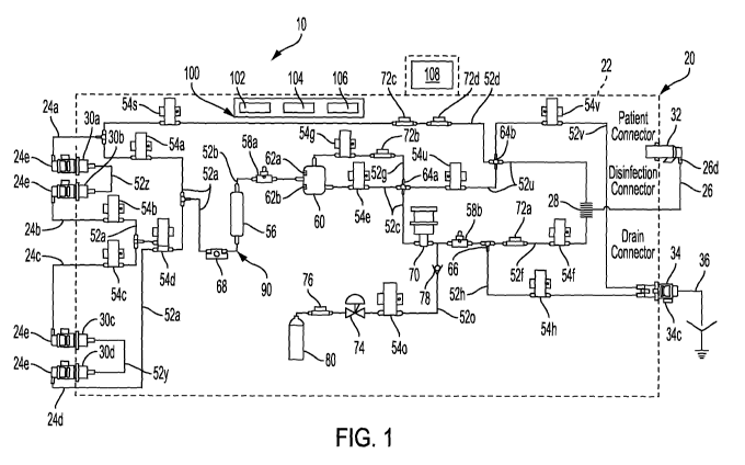
convective
and diffusive clearances. HDF uses dialysis fluid flowing through a dialyzer,
similar to
1
CA 03236092 2024-04-22
WO 2023/122456
PCT/US2022/081526
standard hemodialysis, to provide diffusive clearance. In addition,
substitution solution is
provided directly to the extracorporeal circuit, providing convective
clearance.
[0008] Most HD, HF, and HDF treatments occur in centers. A trend towards home
hemodialysis ("HHD") exists today in part because HHD can be performed daily,
offering
therapeutic benefits over in-center hemodialysis treatments, which occur
typically bi- or tri-
weekly. Studies have shown that more frequent treatments remove more toxins
and waste
products and render less interdialytic fluid overload than a patient receiving
less frequent but
perhaps longer treatments. A patient receiving more frequent treatments does
not experience
as much of a down cycle (swings in fluids and toxins) as does an in-center
patient, who has
built-up two or three days' worth of toxins prior to a treatment. In certain
areas, the closest
dialysis center can be many miles from the patient's home, causing door-to-
door treatment
time to consume a large portion of the day. Treatments in centers close to the
patient's home
may also consume a large portion of the patient's day. HHD can take place
overnight or
during the day while the patient relaxes, works or is otherwise productive.
[0009] Another type of kidney failure therapy is peritoneal dialysis ("PD"),
which
infuses a dialysis solution, also called dialysis fluid, into a patient's
peritoneal chamber via a
catheter. The dialysis fluid is in contact with the peritoneal membrane in the
patient's
peritoneal chamber. Waste, toxins and excess water pass from the patient's
bloodstream,
through the capillaries in the peritoneal membrane, and into the dialysis
fluid due to diffusion
and osmosis, i.e., an osmotic gradient occurs across the membrane. An osmotic
agent in the
PD dialysis fluid provides the osmotic gradient. Used or spent dialysis fluid
is drained from
the patient, removing waste, toxins and excess water from the patient. This
cycle is repeated,
e.g., multiple times.
[0010] There are various types of peritoneal dialysis therapies, including
continuous
ambulatory peritoneal dialysis ("CAPD"), automated peritoneal dialysis
("APD"), tidal flow
dialysis and continuous flow peritoneal dialysis ("CFPD"). CAPD is a manual
dialysis
treatment. Here, the patient manually connects an implanted catheter to a
drain to allow used
or spent dialysis fluid to drain from the peritoneal chamber. The patient then
switches fluid
communication so that the patient catheter communicates with a bag of fresh
dialysis fluid to
infuse the fresh dialysis fluid through the catheter and into the patient. The
patient
disconnects the catheter from the fresh dialysis fluid bag and allows the
dialysis fluid to
dwell within the peritoneal chamber, wherein the transfer of waste, toxins and
excess water
takes place. After a dwell period, the patient repeats the manual dialysis
procedure, for
2
CA 03236092 2024-04-22
WO 2023/122456
PCT/US2022/081526
example, four times per day. Manual peritoneal dialysis requires a significant
amount of
time and effort from the patient, leaving ample room for improvement.
[0011] Automated peritoneal dialysis ("APD") is similar to CAPD in that the
dialysis
treatment includes drain, fill and dwell cycles. APD machines, however,
perform the cycles
automatically, typically while the patient sleeps. APD machines free patients
from having to
manually perform the treatment cycles and from having to transport supplies
during the day.
APD machines connect fluidly to an implanted catheter, to a source or bag of
fresh dialysis
fluid and to a fluid drain. APD machines pump fresh dialysis fluid from a
dialysis fluid
source, through the catheter and into the patient's peritoneal chamber. APD
machines also
allow for the dialysis fluid to dwell within the chamber and for the transfer
of waste, toxins
and excess water to take place. The source may include multiple liters of
dialysis fluid
including several solution bags.
[0012] APD machines pump used or spent dialysate from the patient's peritoneal
cavity, though the catheter, to drain. As with the manual process, several
drain, fill and dwell
cycles occur during dialysis. A "last fill" may occur at the end of the APD
treatment. The
last fill fluid may remain in the peritoneal chamber of the patient until the
start of the next
treatment, or may be manually emptied at some point during the day.
[0013] In any of the above modalities using an automated machine, the
automated
machine operates typically with a disposable set, which is discarded after a
single use.
Depending on the complexity of the disposable set, the cost of using one set
per day may
become significant. Also, daily disposables require space for storage, which
can become a
nuisance for home owners and businesses. Moreover, daily disposable
replacement requires
daily setup time and effort by the patient or caregiver at home or at a
clinic.
[0014] For each of the above reasons, it is desirable to provide an APD
machine that
reduces disposable waste. In doing so, to the extent that deposits of calcium
carbonate are
created via disinfection, such deposits present a problem that may increase
over time. A
need exists accordingly for a PD system having a way to inhibit the production
of calcium
carbonate and/or to remove same if produced.
SUMMARY
[0015] Known automated peritoneal dialysis ("PD") systems typically include a
machine or cycler that accepts and actuates a pumping cassette having a hard
part and a soft
part that is deformable for performing pumping and valving operations. The
hard part is
3
CA 03236092 2024-04-22
WO 2023/122456
PCT/US2022/081526
attached to tubes that extend to various bags. The disposable cassette and
associated tubes
and bags can be cumbersome for a patient at home to load for treatment. The
overall amount
of disposable items may also lead to multiple setup procedures requiring input
from the
patient, which can expose room for error.
[0016] The APD system and associated methodology of the present disclosure, on
the
other hand, convert much of the fluid carrying portions of its PD system into
reusable
components, which are disinfected after treatment. Fluid lines within the
machine or cycler
are reused. Disposable items remaining may include a drain line leading to a
drain bag or
house drain and one or more PD fluid container or bag, such as different
dextrose or glucose
level PD fluid containers and a last bag container, e.g., containing
icodextrine. In an
embodiment, a disposable filter is placed at the distal end of the patient
line to provide a final
stage of PD fluid filtration prior to delivery to the patient.
[0017] The APD system of the present disclosure incudes an APD cycler having a
housing. At least one and perhaps three or more reusable PD fluid lines extend
from the
housing. When not connected to PD fluid containers or bags, the reusable PD
fluid lines can
be connected to disinfection connectors supported and provided by the housing.
The
reusable PD fluid lines may for example extend from a front of the housing and
connect to
disinfection connectors also provided at the front of the housing for ready
access to the PD
fluid lines. The reusable PD fluid lines may be color coded and/or keyed to
match a colored
or keyed connector of the PD fluid container or bag. The containers or bags
may hold
different dextrose or glucose level PD fluids, such as 1.36% glucose PD fluid,
2.27% glucose
PD fluid, 3.86% glucose PD fluid and/or a last bag of a different formulation
of PD fluid,
such as icodextrin. The PD fluids may contain a bicarbonate component.
[0018] Inside the housing, reusable tubing runs from each of the reusable PD
fluid
lines, through a PD fluid supply valve for each PD fluid line, to a PD fluid
inline heater. In
an embodiment, each of the valves of the APD cycler is an electrically
actuated valve having
a reusable valve body that occludes (e.g., when unpowered) or allows (e.g.,
when powered)
PD fluid to flow through the body. The PD fluid inline heater is also
electrically actuated in
one embodiment and is, for example, a resistive heater having a reusable
heater body that
accepts PD fluid for heating. The inline heater in an embodiment is able to
heat PD fluid
from room temperature to body temperature, e.g., 37 C, at a flowrate of at
least 200
milliliters ("m1")/minute. A temperature sensor is located adjacent to the
heater, e.g.,
downstream from the heater to provide feedback for temperature control.
4
CA 03236092 2024-04-22
WO 2023/122456
PCT/US2022/081526
[0019] Reusable tubing runs from the outlet of the PD fluid inline heater to
an airtrap
in one embodiment. Any of the tubing inside the housing of the cycler may be
metal, e.g.,
stainless steel, or plastic, e.g., polyvinylchloride ("PVC") or a non-PVC
material, such as
polyethylene ("PE"), polyurethane ("PU") or polycarbonate ("PC"). In an
embodiment, one
or more level sensor is located adjacent to the airtrap so that a desired
level or range of levels
of PD fluid is/are maintained in the airtrap. A fluid line valve is located
along a reusable
fluid line downstream from the airtrap in an embodiment. At least one gas line
valve located
along at least one gas line may also be provided. The airtrap may be closed
upstream by PD
fluid supply valves to drain the airtrap when dictated by the output of the
level sensors.
[0020] A reusable PD fluid pump is located within the cycler housing and
includes a
reusable pump body that accepts PD fluid for pumping. That is, the pump does
not require
the PD fluid to flow within a disposable item, such as a tube or cassette. The
PD fluid pump
may be an electrically operated piston pump, which is inherently accurate so
that a separate
PD fluid volume measurement apparatus, such as a flowmeter, balance chamber or
an
apparatus using the ideal gas law, is not needed. The PD fluid pump may
alternatively be an
electrically operated, gear or centrifugal pump, which may operate with a
separate PD fluid
volume measurement apparatus.
[0021] The PD fluid pump is controllable to pump to and from the patient at or
below
a pressure limit by controlling a level of current to the PD fluid pump. A
positive patient
pressure limit may for example be one to five psig (e.g., two psig (14 kPa)).
A negative
patient pressure limit may for example be -1.0 psig to -3.0 psig (e.g., -
1.3psig (-9 kPa)). The
PD fluid pump is bidirectional and continuous in one embodiment, such that a
single pump
may be provided.
[0022] The APD cycler of the APD system of the present disclosure includes a
control unit having one or more processor and one or more memory that receives
signals or
outputs from pressure sensors, temperature sensors and possibly a conductivity
sensor and
that processes the signals or outputs as feedback. The control unit uses
pressure feedback to
control the PD fluid pump to run at safe patient pressure limits during
treatment and safe
system limits during disinfection. The control unit uses temperature feedback
to control the
PD fluid heater to heat the fresh PD fluid to, e.g., body temperature.
[0023] The control unit also opens and closes the PD fluid valves in
combination
with the PD fluid pump and heater to run a priming sequence, a patient fill
sequence, a
patient drain sequence, and a disinfection sequence after a PD treatment,
wherein each of the
CA 03236092 2024-04-22
WO 2023/122456
PCT/US2022/081526
at least one reusable PD fluid supply line is connected to one of the at least
one disinfection
connectors, and wherein the reusable patient line is connected to the reusable
patient line
connector. The disinfection sequence readies the APD cycler for the next
treatment. In an
embodiment, unused PD fluid is heated after the final drain and is used for
disinfection.
[0024] The use of unused PD fluid containing bicarbonate as a disinfection
fluid can
lead to the formation of calcium carbonate in the disinfected flowpaths and
flow components
of the PD machine or cycler (forming a disinfection loop). The present system
accordingly
includes a source carbon dioxide (CO2), which is injected during disinfection
to prevent
and/or to remove the formation of calcium carbonate. The CO2 source is placed
in fluid
communication via a CO2 line controlled by a CO2 valve in one embodiment.
[0025] The control unit is programmed to run a sequence that in one embodiment
relies on a table stored in one or more memory of the control unit. The table
in one
implementation sets a pressure increase due to the CO2 injection or an overall
pressure to be
achieved by the CO2 injection as a function of at least one of solution
bicarbonate
composition and/or disinfection temperature setting. Generally, the more
bicarbonate present
in the PD fluid, the higher the pressure needed due to the injected CO2 gas.
And generally,
the higher the disinfection PD fluid temperature, the higher the pressure
needed due to the
injected CO2 gas. Experiments and/or calculations are performed varying
bicarbonate levels
against varied disinfection temperatures to determine how much CO2 gas
pressure is needed
to effectively block the formation of calcium carbonate precipitation, while
efficiently using
CO2 gas, so as not to waste CO2, and so that the CO2 source may be of a
reasonable size,
while still providing many disinfection sequences' worth of CO2.
[0026] The table in another implementation may represent the mole fraction of
CO2,
which depends on the type of disinfection fluid, e.g., PD fluid, the
temperature of the PD
fluid and the pressure of the PD fluid, wherein the mole fraction values
populate the spaces
corresponding to a given temperature and pressure. A desired amount of CO2 is
determined
from a chemical equation in which the addition of CO2 to water contained in
the disinfecting
PD fluid creates carbonic acid, which when combined with calcium carbonate
causes a
chemical reaction that breaks the calcium carbonate into calcium and
bicarbonate ions, which
are suspended in the PD fluid and carried to drain. The control unit here uses
the table to
determine how much the disinfection fluid pressure needs to be increased via
the injection of
CO2 to achieve a desired amount of CO2 (e.g., in mmol). In an embodiment, a
separate mole
fraction table is stored and is accessible by the control unit for each
possible disinfection
6
CA 03236092 2024-04-22
WO 2023/122456
PCT/US2022/081526
fluid or PD fluid, e.g., one for 1.36% glucose PD fluid, another for 2.27%
glucose PD fluid
and a third for 3.86% glucose PD fluid, etc.
[0027] A first step for introducing CO2 into the disinfection loop occurs when
treatment has been completed and it is time for the control unit to perform
disinfection. Prior
to beginning the disinfection sequence, the control unit in one embodiment
with the CO2
valve closed, the PD fluid pump not actuated and the heater unenergized,
accesses a lookup
table (or corresponding algorithm) that sets a pressure to achieve (or
pressure increase) as a
function of the bicarbonate level in the PD fluid used for disinfection and/or
a disinfection
fluid temperature. The control unit in another embodiment takes initial
pressure and
temperature measurements to obtain an initial CO2 mole fraction value from a
stored table for
the particular disinfecting fluid used. An optional pH sensor or CO2 sensor
may be provided
and used alternatively or additionally to determine the CO2 mole fraction,
however, the
lookup table for the particular disinfection fluid will suffice and eliminate
the need for the
extra sensors. In either embodiment, a pressure to achieve, or a pressure
increase, due to CO2
gas injection is obtained and used.
[0028] A second step for introducing CO2 occurs with the PD fluid pump not
actuated and the heater unenergized. The control unit causes the CO2 valve to
open, allowing
CO2 to be injected into the PD fluid within the disinfection loop. The control
unit may cause
the CO2 to be pulsed or injected continuously. In either case, the control
unit monitors the
output of pressure sensor and stops injecting CO2 when the pressure achieves
the needed
pressure increase or overall pressure as determined from either of the lookup
tables discussed
herein.
[0029] A third step for introducing CO2 occurs with the control unit causing
the PD
fluid heater to be energized and the PD fluid pump to be actuated to circulate
heated,
disinfection fluid (PD fluid) about the disinfection loop in any of the
alternative manners
described herein and at the elevated CO2 pressure. The heated disinfection
fluid circulation
takes place for a designated amount of time. During this time, the presence of
the designated
amount of CO2 at the elevated pressure prevents or removes calcium carbonate
(CaCO3)
according to the chemical reaction described herein.
[0030] A fourth, perhaps optional, step for introducing CO2 occurs with the
control
unit causing the PD fluid heater to be de-energized but continuing to allow
the fluid pump to
circulate cooled-down PD fluid. During a cool down period, the control unit
monitors the
output of the pressure sensor to see if the output returns to the pressure
level prior to heating.
7
CA 03236092 2024-04-22
WO 2023/122456
PCT/US2022/081526
If perhaps some leak of CO2 has occurred and the pressure falls below the CO2
injected
pressure, then control unit may cause the CO2 valve to open to allow
additional CO2 to be
injected, e.g., so as to re-reach a desired pressure increase above the
initial, starting pressure.
The ammonia and/or CO2 sensor if provided may be used additionally or
alternatively here to
help meter additional CO2 into the disinfection loop.
[0031] In light of the disclosure set forth herein, and without limiting the
disclosure
in any way, in a first aspect of the present disclosure, which may be combined
with any other
aspect, or portion thereof, a peritoneal dialysis ("PD") system includes a PD
fluid pump; a
disinfection loop including the PD fluid pump, the disinfection loop including
PD fluid used
for disinfecting the disinfection loop; and a carbon dioxide (CO2), source
positioned and
arranged to supply CO2 to the disinfection loop to inhibit and/or remove the
production of
calcium carbonate (CaCO3) during a disinfection sequence.
[0032] In a second aspect of the present disclosure, which may be combined
with any
other aspect, or portion thereof, the PD system includes a CO2 valve located
between the
disinfection loop and the CO2 source, the CO2 valve opened to allow the CO2 to
be supplied
to the disinfection loop.
[0033] In a third aspect of the present disclosure, which may be combined with
any
other aspect, or portion thereof, the PD system includes a control unit
configured to cause the
CO2 valve to open to allow the CO2 to pressurize the PD fluid to a desired
pressure or
pressure increase to inhibit and/or remove the production of calcium carbonate
during the
disinfection sequence.
[0034] In a fourth aspect of the present disclosure, which may be combined
with any
other aspect, or portion thereof, the PD system includes at least one pressure
sensor
outputting to the control unit, the control unit configured to monitor the at
least one pressure
sensor output to detect the desired pressure or pressure increase.
[0035] In a fifth aspect of the present disclosure, which may be combined with
any
other aspect, or portion thereof, the control unit is configured to use a
lookup table to
determine the desired pressure or pressure increase.
[0036] In a sixth aspect of the present disclosure, which may be combined with
any
other aspect, or portion thereof, the control unit stores a disinfection
temperature to which the
PD fluid is heated for the disinfection sequence, and wherein the desired
pressure or pressure
increase in the lookup table corresponds to the disinfection temperature.
8
CA 03236092 2024-04-22
WO 2023/122456
PCT/US2022/081526
[0037] In a seventh aspect of the present disclosure, which may be combined
with
any other aspect, or portion thereof, the PD system includes at least one
temperature sensor
outputting to the control unit, the control unit configured to monitor the at
least one
temperature sensor output to detect the disinfection temperature.
[0038] In an eighth aspect of the present disclosure, which may be combined
with
any other aspect, or portion thereof, the lookup table is specific to the type
of PD fluid used
for disinfection.
[0039] In a ninth aspect of the present disclosure, which may be combined with
any
other aspect, or portion thereof, the control unit knows a bicarbonate level
for the PD fluid
used for disinfection, and wherein the desired pressure or pressure increase
in the lookup
table corresponds to the bicarbonate level.
[0040] In a tenth aspect of the present disclosure, which may be combined with
any
other aspect, or portion thereof, the control unit is configured to take
initial pressure and
temperature readings prior to supplying CO2 to the disinfection loop, the
control unit further
configured to determine the initial amount of CO2 contained in the
disinfection loop using the
lookup table and the initial pressure and temperature readings.
[0041] In an eleventh aspect of the present disclosure, which may be combined
with
any other aspect, or portion thereof, the control unit is configured to use an
algorithm to
determine the desired pressure or pressure increase.
[0042] In a twelfth aspect of the present disclosure, which may be combined
with any
other aspect, or portion thereof, the control unit is configured to cause the
CO2 valve to open
to allow the CO2 to pressurize the PD fluid to the desired pressure or
pressure increase prior
to causing the PD fluid pump to run during the disinfection sequence.
[0043] In a thirteenth aspect of the present disclosure, which may be combined
with
any other aspect, or portion thereof, the control unit is configured to cause
the CO2 valve to
open to allow the CO2 to pressurize the PD fluid to the desired pressure or
pressure increase
while causing the PD fluid pump to run during the disinfection sequence.
[0044] In a fourteenth aspect of the present disclosure, which may be combined
with
any other aspect, or portion thereof, the PD system includes a PD fluid
heater, and wherein
the control unit is configured to cause the CO2 valve to open to allow the CO2
to pressurize
the PD fluid to the desired pressure or pressure increase prior to causing the
PD fluid heater
to heat the PD fluid during the disinfection sequence.
9
CA 03236092 2024-04-22
WO 2023/122456
PCT/US2022/081526
[0045] In a fifteenth aspect of the present disclosure, which may be combined
with
any other aspect, or portion thereof, the PD system includes a PD fluid
heater, and wherein
the control unit is configured to cause the CO2 valve to open to allow the CO2
to pressurize
the PD fluid to the desired pressure or pressure while causing the PD fluid
heater to heat the
PD fluid during the disinfection sequence.
[0046] In a sixteenth aspect of the present disclosure, which may be combined
with
any other aspect, or portion thereof, the control unit is configured to cause
the CO2 valve to
open to allow the CO2 to pressurize the PD fluid during a cool down period if
a loss of
pressure is detected by the control unit.
[0047] In a seventeenth aspect of the present disclosure, which may be
combined
with any other aspect, or portion thereof, any of the features, functionality
and alternatives
described in connection with any one or more of Figs. 1 to 7 may be combined
with any of
the features, functionality and alternatives described in connection with any
other of Figs. 1
to 7.
[0048] It is accordingly an advantage of the present disclosure to provide a
system for
an automated peritoneal dialysis ("APD") cycler that helps to ensure that
calcium carbonate
production is inhibited or that calcium carbonate is cleaned and removed
during disinfection.
[0049] It is another advantage of the present disclosure to provide a system
for an
APD cycler that efficiently uses carbon dioxide (CO2) during disinfection to
prevent or
remove the development of calcium carbonate.
[0050] It is a further advantage of the present disclosure to provide a system
for an
APD cycler that helps to prevent the build-up of precipitates during
disinfection.
[0051] Additional features and advantages are described in, and will be
apparent
from, the following Detailed Description and the Figures. The features and
advantages
described herein are not all-inclusive and, in particular, many additional
features and
advantages will be apparent to one of ordinary skill in the art in view of the
figures and
description. Also, any particular embodiment does not have to have all of the
advantages
listed herein and it is expressly contemplated to claim individual
advantageous embodiments
separately. Moreover, it should be noted that the language used in the
specification has been
selected principally for readability and instructional purposes, and not to
limit the scope of
the inventive subject matter.
CA 03236092 2024-04-22
WO 2023/122456
PCT/US2022/081526
BRIEF DESCRIPTION OF THE FIGURES
[0052] Fig. 1 is a schematic view of one embodiment of an automated peritoneal
dialysis ("APD") machine or cycler and associated system of the present
disclosure.
[0053] Fig. 2 is a simplified schematic view of one embodiment of an automated
peritoneal dialysis ("APD") machine or cycler of the present disclosure after
treatment and
prior to disinfection.
[0054] Fig. 3 is a simplified schematic view of one embodiment of an automated
peritoneal dialysis ("APD") machine or cycler of the present disclosure
delivering CO2 to a
disinfection loop.
[0055] Fig. 4 is a simplified schematic view of one embodiment of an automated
peritoneal dialysis ("APD") machine or cycler of the present disclosure
pumping heated PD
disinfection fluid containing delivered CO2 during disinfection.
[0056] Fig. 5 is a simplified schematic view of one embodiment of an automated
peritoneal dialysis ("APD") machine or cycler of the present disclosure
optionally delivering
CO2 to the disinfection loop during a cool down period.
[0057] Fig. 6 is an example lookup table stored in a control unit of an
automated
peritoneal dialysis ("APD") machine or cycler of the present disclosure, the
lookup table
providing a pressure to achieve, or a pressure increase, due to CO2 injection,
wherein the
pressure is based on at least one of an amount of bicarbonate in the PD
disinfection fluid
and/or a disinfection fluid temperature.
[0058] Fig. 7 is an example alternative lookup table stored in a control unit
of an
automated peritoneal dialysis ("APD") machine or cycler of the present
disclosure, the
lookup table providing a pressure to achieve, or a pressure increase, due to
CO2 injection,
wherein the pressure is based on a mole fraction of CO2.
DETAILED DESCRIPTION
System Generally
[0059] Referring now to the drawings and in particular to Fig. 1, automated
peritoneal dialysis ("APD") system 10 and associated methodology of the
present disclosure
includes an APD machine or cycler 20. System 10 and cycler 20 attempt to
eliminate
disposable items as much as possible and instead provide the majority of its
fluid carrying
portions as reusable components, which are disinfected after treatment. Fluid
lines within the
11
CA 03236092 2024-04-22
WO 2023/122456
PCT/US2022/081526
machine or cycler are reused. In particular, Fig. 1 illustrates that cycler 20
includes a
housing 22 from which reusable PD fluid supply lines 24a to 24d extend. Fig 1
further
illustrates that a reusable patient line 26 also extends from housing 22 of
machine or cycler
20. Reusable patient line 26, which is typically longer than reusable PD fluid
supply lines
24a to 24d, may be coiled or rolled up within the housing via a spool or hose
reel 28 when
reusable patient line 26 is not connected to a patient for treatment.
[0060] When not connected to PD fluid containers or bags, the reusable PD
fluid
supply lines 24a to 24d and patient line 26 can be connected to dedicated
connectors
supported and provided by housing 22. The reusable PD fluid supply and patient
lines may
for example extend from a front of housing 22 and connect to connectors also
provided at the
front of the housing for ready access to the PD fluid and patient lines. In
the illustrated
embodiment, distal ends 24e of reusable PD fluid supply lines 24a to 24d
releasably attach in
a fluid-tight manner to disinfection connectors 30a to 30d, respectively,
provided at housing
22. Distal end 26d of reusable patient line 26 releasably attaches in a fluid-
tight manner to
patient line connector 32 provided at housing 22. Disinfection connectors 30a
to 30d and
patient line connector 32 are configured in one embodiment to close or shut
automatically
when reusable PD fluid supply lines 24a to 24d and reusable patient line 26,
respectively, are
removed or not connected to the connectors.
[0061] Fig. 1 also illustrates that housing 22 provides a drain line connector
34,
which may be releasably covered by a moveable, e.g., rotatable or slideable
cover 34c. Drain
line connector 34 receives a disposable drain line 36 for treatment, which may
run to a drain
container or bag or to a house drain. Disposable drain line 36 is disconnected
from drain line
connector 34 during disinfection.
[0062] Disposable PD fluid or solution containers or bags (not illustrated
because
system 10 is in a disinfection configuration with the containers or bags
removed) are
connected respectively to reusable PD fluid supply lines 24a to 24d. Distal
ends 24e of
reusable PD fluid supply lines 24a to 24d may be color coded and/or keyed to
match a
colored or keyed connector of a dedicated PD fluid container or bag. The
containers or bags
may hold the same or different dextrose or glucose level PD fluids, such as
1.36% glucose
PD fluid, 2.27% glucose PD fluid, 3.86% glucose PD fluid and/or a last bag of
a different
formulation of PD fluid, such as icodextrin.
[0063] It should be appreciated that any number of reusable PD fluid supply
lines 24a
to 24d and PD fluid containers or bags may be provided, including a single
reusable PD fluid
12
CA 03236092 2024-04-22
WO 2023/122456
PCT/US2022/081526
line and PD fluid container or more than one reusable PD fluid lines and PD
fluid containers.
In a further alternative embodiment, the PD fluid containers or bags are
replaced by an online
PD fluid generation source, which connects to and communicates fluidly with a
single
reusable PD fluid supply line.
[0064] Besides disposable drain line 36 (and associated container if used) and
the
disposable PD fluid containers or bags, it is contemplated that in one
embodiment, the only
other disposable component of system 10 is a disposable filter set (not
illustrated) removably
connected by the patient at the distal end 26d of reusable patient line 26 to
provide a final
stage of PD fluid filtration prior to delivery to the patient. In an
embodiment, the disposable
filter set is spliced between the distal end 26d of reusable patient line 26
and the patient's
transfer set, which leads to an indwelling PD catheter inserted into the
patient.
[0065] It is contemplated that any one, or more, or all of reusable PD fluid
supply
lines 24a to 24d, reusable patient line 26, disinfection connectors 30a to
30d, patient line
connector 32, drain line connector 34, drain line 36, the PD fluid containers
or bags and the
patient line filter set be made of any one or more plastic, e.g.,
polyvinylchloride ("PVC") or a
non-PVC material, such as polyethylene ("PE"), polyurethane ("PU"),
polypropylene ("PP")
or polycarbonate ("PC").
[0066] Fig. 1 further illustrates that reusable supply tube 52a runs from each
reusable
PD fluid supply line 24a to 24d, via a PD fluid supply valve 54a to 54d,
respectively, to a PD
fluid inline heater 56. In an embodiment, each of the valves of APD cycler 20,
including PD
fluid supply valves 54a to 54d, is an electrically actuated valve having a
reusable valve body
that occludes (e.g., when unpowered for fail safe operation) or allows (e.g.,
when powered)
PD fluid to flow through the body. In the illustrated embodiment, valve 54d is
a three-way
valve having a normally open port for receiving PD fluid from reusable PD
fluid supply line
24b or 24c and a normally closed port for receiving PD fluid from reusable PD
fluid supply
line 24d. PD fluid inline heater 56 is also electrically actuated in one
embodiment and is, for
example, a resistive heater having a reusable heater body that accepts PD
fluid for treatment
and for disinfection heating. Inline heater 56 in an embodiment is able to
heat PD fluid from
room temperature or colder (e.g., if the PD fluid is stored in a cold
environment) to body
temperature, e.g., 37 C, at a flowrate of up to at least 200 milliliters
("m1")/minute.
[0067] A first temperature sensor 58a is located adjacent to inline heater 56,
e.g.,
downstream from the heater to provide feedback for temperature control. If
desired, a second
temperature sensor (not illustrated) may be provided upstream from PD fluid
heater 56 to
13
CA 03236092 2024-04-22
WO 2023/122456
PCT/US2022/081526
enable the incoming temperature of fresh PD fluid to be taken into account for
the heating
algorithm. A second temperature sensor 58b is illustrated just downstream from
PD fluid
pump 70, which is provided for example as a second check that fresh PD fluid
exiting PD
fluid pump 70 is at a desired temperature for treatment, e.g., body
temperature or 37 C.
[0068] In the illustrated embodiment, a flow switch 68 is located just
upstream from
PD fluid inline heater 56. An output from flow switch 68 is used to make sure
there is PD
fluid flow through inline heater 56. If the output (or lack thereof) from flow
switch 68
indicates no or little PD fluid flow, which could be harmful to inline heater
56 if powered,
causes system 10 to halt power to inline heater 56 and to stop treatment or
disinfection if
needed while (i) attempting to find a remedy to the no or low flow situation
or (ii) causing an
audio, visual or audiovisual alarm or alert at user interface 108. Alternative
ways for
ensuring flow to the inline heater 56 in order to power the heater may be used
alternatively.
[0069] Reusable tube 52b runs from the outlet of PD fluid inline heater 56 to
an
airtrap 60 in the illustrated embodiment of Fig. 1. Any of the reusable tubing
inside the
housing of cycler 20, including reusable tubes 52a and 52b, may be made of
metal, e.g.,
stainless steel or plastic, e.g., polyvinylchloride ("PVC") or a non-PVC
material, such as
polyethylene ("PE"), polyurethane ("PU"), polypropylene ("PP"), polyether
ether ketone
("PEEK"), or polycarbonate ("PC"). In an embodiment, one or more level sensor
62a and
62b is located adjacent airtrap 60, so that a desired level or range of levels
of PD fluid is/are
maintained in the airtrap. A fluid line valve 54e is located downstream from
airtrap 60 in the
illustrated embodiment and receives fresh, heated PD fluid from the airtrap. A
gas line valve
54g is located along a gas line 52g extending from a top of airtrap 60.
Airtrap 60 may be
closed upstream by PD fluid supply valves 54a to 54d to drain the airtrap when
dictated by
the output of level sensor 62a or 62b.
[0070] A reusable fluid line 52c and gas line 52g run between fluid line valve
54e
and gas line valve 54g, respectively, and a PD fluid pump 70 located within
housing 22 of
cycler 20. PD fluid pump 70 includes a reusable pump body that accepts PD
fluid for
pumping. That is, pump 70 does not require the PD fluid to flow within a
disposable item,
such as a tube or cassette. The reusable pump body of pump 70 itself accepts
the PD fluid.
PD fluid pump 70 may be of a type, e.g., piston pump, which is inherently
accurate so that a
separate PD fluid volume measurement apparatus, such as a balance chamber or
flowmeter,
is not needed. PD fluid pump 70 may alternatively be a less accurate gear or
centrifugal
pump that does operate with a PD fluid volume measurement apparatus. PD fluid
pump 70 is
14
CA 03236092 2024-04-22
WO 2023/122456
PCT/US2022/081526
controllable to pump to and from the patient at or below a pressure limit by
controlling a
level of current to the PD fluid pump. A positive patient pressure limit may
for example be
one to five psig (e.g., two psig (14 kPa)). A negative patient pressure limit
may for example
be -1.0 psig to -3.0 psig (e.g., -1.3psig (-9 kPa)). PD fluid pump 70 is also
capable of
supplying lower pressures if needed, e.g., for small children or babies. PD
fluid pump 70 is
bidirectional and continuous in one embodiment, such that a single pump may be
provided.
[0071] Fig. 1 further illustrates that a fresh PD fluid patient line valve 54f
is located
in an embodiment along reusable fresh PD fluid patient tube or line 52f
between downstream
temperature sensor 58b and spool or hose reel 28. Fresh PD fluid patient tube
or line 52f
communicates fluidly with a fresh PD fluid lumen of dual lumen reusable
patient line 26 in
one embodiment. A used PD fluid patient line valve 54u is located in an
embodiment along
reusable used PD fluid patient tube or line 52u between PD fluid pump 70 (via
cross 64a) and
spool or hose reel 28. Used PD fluid patient tube or line 52u communicates
fluidly with a
used PD fluid lumen of dual lumen reusable patient line 26 in one embodiment.
A drain line
valve 54h is located along reusable drain tube or line 52h that extends from a
tee 66 to drain
line connector 34.
[0072] A first patient pressure sensor 72a is located along fresh PD fluid
patient tube
or line 52f between PD fluid pump 70 and spool or hose reel 28 to measure
positive patient
PD fluid pressure. A second patient pressure sensor 72b is located along gas
line 52g to
measure negative patient PD fluid pressure during a patient drain (gas is at
same negative
pressure as used PD fluid via fluid communication at cross 64a). Third and
fourth pressures
sensor 72c and 72d are located along reusable disinfection tube or line 52d.
[0073] As discussed above, patient line connector 32 is located at APD cycler
housing 22 and accepts dual lumen reusable patient line 26 during disinfection
and generally
while the patient is not undergoing treatment. Patient line connector 32 in
one embodiment
includes a sealed fluidic U-turn or 180 degree turn that allows disinfection
fluid, e.g., heated
PD fluid, to flow from one lumen of the dual lumen patient line to another
lumen of the dual
lumen patient line. Dual lumen reusable patient line 26 is therefore included
in the
disinfection loop.
[0074] As further discussed above, drain line 36 is flexible and disposable in
one
embodiment and connects to drain line connector 34 extending from housing 22
of APD
cycler 20 during treatment. After treatment, drain line 36 may be removed
during the
disinfection sequence. Drain line connector 34 receives an internal, reusable
drain tube or
CA 03236092 2024-04-22
WO 2023/122456
PCT/US2022/081526
line 52h for delivering used PD fluid to drain line 36 during a patient drain.
Drain line
connector 34 also receives vent tube or line 52v for delivering gas, such as
air or carbon
dioxide (CO2), to drain line 36 during treatment. A vent valve 54v is located
along vent tube
or line 52v.
[0075] A reusable disinfection tube or line 52d as illustrated in Fig. 1
extends to a
second cross 64b along with vent tube or line 52v and used PD fluid patient
tube or line 52u.
Reusable disinfection tube or line 52d includes a disinfection valve 54s.
Disinfection tube or
line 52d handles disinfection fluid, e.g., fresh, heated PD fluid, vent tube
or line 52v handles
vented gas, e.g., air, while used PD fluid patient tube or line 52u handles
used PD fluid
during treatment.
[0076] A bypass line 52y as illustrated in Fig. 1 is located between
disinfection
connectors 30c and 30d for use during disinfection. A similar bypass line 52z
is provided
between disinfection connectors 30a and 30b. During disinfection, heated
disinfection fluid,
such as PD fluid, is directed through bypass lines 52y and 52z to fully
disinfect disinfection
connectors 30a to 30d.
[0077] Fig. 1 also illustrates that system 10 includes a carbon dioxide (CO2)
source
80, which may be connected fluidly to the disinfection loop for example
between PD fluid
pump 70 and pressure sensor 72a, e.g., via CO2 line 52o. A CO2 valve 54o is
located along
CO2 line 52o. As discussed in detail below, system 10 causes a desired and
efficient amount
of CO2 gas to be metered from CO2 source 80 into the disinfection fluid, e.g.,
PD fluid, just
prior to disinfection to prevent and/or remove any build-up of calcium
carbonate (CaCO3) as
the PD fluid is heated. CO2 source 80 may for example be initially pressurized
to 70 kPa (10
psig) to provide ample pressure over multiple disinfection sequences according
to the
pressurization scheme discussed herein.
[0078] Fig. 1 further illustrates that a gas or CO2 pressure regulator 74 and
a CO2
pressure sensor 76 may optionally be located along CO2 line 52o upstream from
CO2 valve
54o. CO2 pressure regulator 74 enables CO2 source 80 to be pressurized to a
higher level so
that is lasts longer. Regulator 74 then regulates the high incoming pressure
from CO2 source
80 down to a smoothly outputted desired output pressure. The desired operating
pressure for
example may be slightly above the pressures (or pressure increases) to be
achieved, which
are obtained from table 110 or table 120 as discussed below in connection with
Figs. 6 and 7,
respectively. CO2 pressure sensor 76 reads and outputs a pressure
corresponding to the CO2
16
CA 03236092 2024-04-22
WO 2023/122456
PCT/US2022/081526
pressure remaining within CO2 source 80. A one-way or check valve 78 may also
be
provided and oriented so as to prevent fresh or used PD fluid from entering
CO2 line 52o.
[0079] Fig. 1 still further illustrates that APD cycler 20 of system 10 of the
present
disclosure includes a control unit 100 having one or more processor 102 and
one or more
memory 104 that receive, store and process signals or outputs from the
pressure sensors 72a
to 72d, CO2 pressure sensor 76 if provided, temperature sensors 58a and 58b,
flow switch 68
and possibly a conductivity sensor (not illustrated). Control unit 100 uses
pressure feedback
from pressure sensors 72a and 72b to control PD fluid pump 70 to pump fresh
and used PD at
safe patient and system pressure limits. Control unit 100 uses temperature
feedback from
temperature sensor 58a to control inline PD fluid heater 56 to heat the fresh
PD fluid to, e.g.,
body temperature or 37 C for treatment, and to 85 C for disinfection. Control
unit 100 uses
flow switch feedback from flow switch 68 to determine whether to power PD
fluid inline
heater 56. Control unit 100 as discussed herein further uses feedback from
pressure sensor
72a (and perhaps pressure sensor 72b) to determine how much CO2 has been
delivered to a
disinfection loop via CO2 line 52o.
[0080] Control unit 100 as illustrated in Fig. 1 also includes a video
controller 106
that interfaces with a user interface 108, which may include a display screen
operating with a
touchscreen and/or one or more electromechanical button, such as a membrane
switch. User
interface 108 may also include one or more speaker for outputting alarms,
alerts and/or voice
guidance commands. User interface 108 may be provided with cycler 20 as
illustrated in Fig.
1 and/or be a remote user interface operating with control unit 100. Control
unit 100 may
also include a transceiver (not illustrated) and a wired or wireless
connection to a network,
e.g., the internet, for sending treatment data to and receiving prescription
instructions from a
doctor's or clinician's server interfacing with a doctor's or clinician's
computer.
[0081] Control unit 100 opens and closes PD fluid valves 54a to 54h, 54o, 54s,
54u
and 54v in combination with the operation of PD fluid pump 70 and inline
heater 56 to run a
priming sequence, multiple patient fill sequences, multiple patient drain
sequences, and a
disinfection sequence after a PD treatment. The disinfection sequence readies
APD cycler 20
for the next treatment. In an embodiment, remaining fresh PD fluid is heated
after the final
patient drain and is used as the disinfection fluid for disinfection.
[0082] To form a disinfection loop 90 for the disinfection sequence, each
reusable PD
fluid supply line 24a to 24d is connected to a respective disinfection
connector 30a to 30d,
reusable patient line 26 is connected to reusable patient line connector 32,
and drain line 36 is
17
CA 03236092 2024-04-22
WO 2023/122456
PCT/US2022/081526
removed in one embodiment, so that drain line connector 34 may close shut. As
illustrated in
Fig. 1, disinfection loop 90 includes patient line connector 32 (including its
U-turn or 180
degree turn), both lumens of reusable dual lumen patient line 26, used PD
fluid patient tube
or line 52u, reusable disinfection tube or line 52d, reusable drain tube or
line 52h, vent tube
or line 52v, drain line connector 34, reusable PD fluid supply lines 24a to
24d, bypass lines
52y, 52z, and reusable tubes or lines 52a to 52c and 52f. Disinfection loop 90
also includes
the insides of all flow components and fluid-contacting sensors located along
the above-listed
lines.
[0083] Control unit 100 may sequence certain of the valves along disinfection
loop
90 during disinfection. For example, PD fluid supply valve 54a may be
sequenced open and
closed during disinfection to allow disinfection fluid to flow through supply
valve 54a or be
forced completely through reusable PD fluid supply line 24a. Control unit 100
may also
cause PD fluid pump 70 to run sequentially in forward and reverse states
during disinfection,
so that the disinfection fluid may flow clockwise and counterclockwise through
disinfection
loop 90. Control unit 100 also causes inline heater 56 to heat the
disinfection fluid, e.g.,
fresh PD fluid, to a desired disinfection temperature, such as 70 C to 95 C.
[0084] The use of PD fluid containing bicarbonate as a disinfection fluid
likely leads
to the formation of calcium carbonate (CaCO3) in the disinfected flowpaths and
flow
components of disinfection loop 90 of PD machine or cycler 20. Carbon dioxide
(CO2) from
source 80 is provided accordingly just prior to disinfection to prevent and/or
to remove the
formation of calcium carbonate. Figs. 2 to 5 illustrate a simplified version
of disinfection
loop 90, showing important components to the CO2 injection from source 80,
including PD
fluid inline heater 56, first temperature sensor 58a, PD fluid pump 70, fresh
PD fluid patient
pressure sensor 72a, CO2 source 80, CO2 line 52o, CO2 valve 54o and control
unit 100. It
should be appreciated however that the sequences described in connection with
Figs. 2 to 5
are equally applicable to the full disinfection loop 90 of PD machine or
cycler 20 of system
in Fig. 1.
Lookup Table Based on
Bicarbonate Level and/or Disinfection Temperature
[0085] Referring now to Fig. 6, the sequences of Figs. 2 to 5 in an embodiment
rely
on a table 110 (or corresponding algorithm) stored in one or more memory 104
of control
unit 100, which sets a pressure to achieve, or a pressure increase, due to the
injection of CO2
based on at least one of a bicarbonate level in the PD disinfection fluid or a
disinfection fluid
18
CA 03236092 2024-04-22
WO 2023/122456
PCT/US2022/081526
temperature. As illustrated in Fig. 6, table 100 sets a pressure increase due
to the CO2
injection or an overall pressure to be achieved (PH to P46) by the CO2
injection as a function
of at least one of solution bicarbonate composition Om to b4) and disinfection
fluid
temperature setting (Ti to T6). Fig. 6 accordingly illustrates the pressure
(or pressure
increase) to achieve as a function of both bicarbonate level and disinfection
fluid temperature
setting in a two dimensional array. Fig. 6 could alternatively however base
the pressure (or
pressure increase) to achieve as a function of only one of bicarbonate level
or disinfection
fluid temperature
[0086] Generally, the more bicarbonate present in the fresh PD fluid, the
higher the
pressure in table 110 needed due to the injected CO2 gas. And generally, the
higher the
disinfection PD fluid temperature, the higher the pressure in table 110 needed
due to the
injected CO2 gas. To populate table 110, experiments and/or calculations are
performed
varying bicarbonate levels against varied disinfection fluid temperatures to
determine how
much CO2 gas pressure is needed to effectively block the formation of calcium
carbonate
precipitation, while efficiently using CO2 gas, so as not to waste CO2, and so
that the CO2
source 80 may be of a reasonable size, while still providing many disinfection
sequence's
worth of CO2.
[0087] Control unit 100 at the beginning of each disinfection sequence knows
the
bicarbonate level from the prescribed PD fluid used for the just-ended
treatment. Control
unit 100 also knows and sets the disinfection fluid temperature, which may be
the same or be
different for different disinfection sequences. Control unit 100 accesses
table 110 (or
corresponding algorithm) and finds the operating pressure (or pressure
increase) to achieve
based on the known bicarbonate level and the known disinfection fluid
temperature. It
should be appreciated that table 110 could alternatively compare disinfection
fluid
temperature against the type of bicarbonate-based PD fluid used, which is
basically the same
as comparing disinfection fluid temperature against bicarbonate level. It
should also be
appreciated that PD fluids not containing bicarbonate do not have the
precipitation issues
discussed herein. So when using a PD fluid for disinfection that does not
contain
bicarbonate, control unit 100 does not access table 110 and does not inject
CO2 gas from CO2
source 80.
Lookup Table Based on Mole Fraction
[0088] Referring now to Fig. 7, the sequences of Figs. 2 to 5 in an
alternative
embodiment rely on a table 120 (or corresponding algorithm) stored in one or
more memory
19
CA 03236092 2024-04-22
WO 2023/122456
PCT/US2022/081526
104 of control unit 100, which uses a mole fraction of CO2. Table 120 of Fig.
7 represents
the mole fraction of CO2, which depends on the type of disinfection fluid,
e.g., type of PD
fluid, PD fluid temperature (left-hand column, C) and PD fluid pressure
(upper row, kPA),
wherein the mole fraction values populate the spaces corresponding to a given
temperature
and pressure. In an embodiment, a separate table (like table 120) is stored
and is accessible
by control unit 100 for each possible disinfection fluid or PD fluid, e.g.,
one for 1.36%
glucose PD fluid, another for 2.27% glucose PD fluid and a third for 3.86%
glucose PD fluid.
[0089] In one example for using a table 120 in Fig. 7, the following
information is
taken as being known and may be stored (or a portion thereof) in control unit
100:
= disinfection loop 90 volume is 200m1
= CO2 source 80 holds 18g of CO2
= CO2 molar mass is 44.01 g/mol
= CaCO3 molar mass is 100.0869 g/mol
= disinfection fluid molar mass (assume that of H20) is 18.02 g/mol
= disinfection fluid H20 density (assume that of H20) is 0.96859 g/m1
= calcium content (Ca)' of disinfection fluid is 1.25mmo1/L)
[0090] On a per disinfection sequence basis using the following chemical
reaction for
eliminating calcium carbonate, where H2CO3 is carbonic acid and HCO3 is
bicarbonate, and
wherein H20 is obtained from the PD fluid used for disinfection:
Therefore CaCO3 5lissolves 0 Extra H2CO3 forms
0 Reaction shifts toward nght
to reOace lost bicarbonate
Ca CO3 (s) + H2CO3 (aq) # Ca2 (aq) + HCO3- (aq)
CO2 [g] + H20 (I)
0 844 coa
= max CaCO3 = 1.25x 0.2 mmol = 0.25 mmol ¨> 0.25e-3 x 100.0869 g =
0.025021725 g CaCO3
= 1 mmol Ca' ¨> 2mmo1 H+
= needed CO2 = 2xmmo1 CaCO3 = 0.5 mmol CO2 ¨> 0.5e-3 x44.01 g = 0.022005 g
CO2
= one tank of 18g CO2with an effective use of 45% ¨> 18 / 0.022005 x 0.45 =
368
cycles of CO2
CA 03236092 2024-04-22
WO 2023/122456
PCT/US2022/081526
[0091] A goal of the CO2 injection is to increase the pressure measured by
pressure
sensor 72a, so that dissolved CO2 is maintained during the heated disinfection
sequence at a
predetermined amount calculated above to be 0.5 mmol. An assumption that the
source of
PD fluid used for disinfection, e.g., a bag of such fluid, is in equilibrium
with the ambient
surroundings regarding temperature and pressure is made, such that the initial
partial pressure
of CO2 may be assumed to be roughly 0.04 kPa (partial pressure of CO2 at
ambient). Using
table 120 of Fig. 7, and extrapolating from the 0.031 molar fraction valve at
5 kPa and 25 C
yields about 0.00031 molar fraction of CO2 at normal ambient conditions ((0.04
kPa/5 kPa) is
roughly 1/10 of 0.031, which equals 0.00031 molar fraction).
[0092] In the example it is also assumed (and would be known in a commercial
implementation) that the volume of disinfection or PD fluid circulated in
disinfection loop 90
is 200 milliliters ("m1"). Knowing the density of the PD disinfection fluid
(using density of
water in the example), 200 ml of PD fluid equals 193.72 grams or 10.75 mols of
the fluid in
disinfection loop 90. At normal ambient conditions (5 kPa and 25 C) 10.75 mols
x 0.00031
molar fraction yields 0.0033 mmols of CO2, which drops to 0.0012 mmols CO2 at
85 C
(0.00011 molar fraction x 10.75 mols) as extrapolated from table 120 of Fig. 7
for 0.04 kPa
at 85 C, which is a typical disinfection temperature. The drop dictates that
0.5012 (0.0012+
0.5) mmols of CO2 needs to be injected into the heated PD fluid. 0.5012
(0.0012+ 0.5)
mmols of CO2 in turn yields a needed molar fraction of 0.5012/10.75 = 0.0466,
which in turn
yields a partial pressure increase of about 21 kPa (3 psig) at 85 C according
to table 120 of
Fig. 7.
[0093] Using the table 120 of Fig. 7 and the above knowns based on solid
assumptions, which are programmed into control unit 100, control unit 100 can
thereby
calculate for a given PD fluid to be used as a disinfecting fluid, and a given
disinfection
temperature (each of which may be programmed into control unit 100 at the time
of
treatment, or be known from a patient's prescription), the pressure at which
the disinfecting
PD fluid needs to be increased via CO2 pressure from source 80, wherein the
pressure is set
in one embodiment by downstream CO2 pressure regulator 74.
CO2 Injection Steps
[0094] Fig. 2 illustrates a first step in which a PD treatment has been
completed and it
is time for control unit 100 to perform disinfection. Prior to beginning the
disinfection
sequence, control unit 100 in one embodiment, with CO2 valve 54o closed (not
shaded), PD
fluid pump 70 not actuated and inline heater 56 unenergized, finds the
pressure (or pressure
21
CA 03236092 2024-04-22
WO 2023/122456
PCT/US2022/081526
increase) to be achieved from table 110 of Fig. 6 based on a known bicarbonate
level and/or
disinfection temperature. Control unit 100 in an alternative embodiment, with
CO2 valve 54o
closed, PD fluid pump 70 not actuated and inline heater 56 unenergized, takes
initial pressure
and temperature measurements via pressure sensor 72a and temperature sensor
58a,
respectively, to obtain an initial CO2 mole fraction value from the table 120
of Fig. 7. An
optional pH sensor or CO2 sensor (not illustrated) may be provided and used
alternatively or
additionally to determine the initial CO2 mole fraction, however, the table
120 of Fig. 7 for
the disinfection fluid will suffice and eliminates the need for extra sensors.
[0095] Fig. 3 illustrates a second step in which control unit 100, with PD
fluid pump
70 not actuated and inline heater 56 unenergized, causes CO2 valve 54o to open
(valve
shaded), allowing CO2 to be injected into the PD fluid within disinfection
loop 90. Control
unit 100 may pulse CO2 or inject the CO2 continuously, but in either case
control unit 100
monitors the output of pressure sensor 72a and stops injecting CO2 when the
pressure
achieves the needed pressure (or pressure increase (e.g., about 21 kPa (3
psig) at 85 C)) from
table 110 of Fig. 6 or table 120 of Fig. 7.
[0096] Fig. 4 illustrates a third step in which control unit 100 causes inline
heater 56
to be energized and PD fluid pump 70 to circulate heated, disinfection fluid
(PD fluid) about
disinfection loop 90 in any of the alternative manners described above and at
the elevated
pressure obtained in Fig. 3. Heated disinfection fluid circulation takes place
for a designated
amount of time. During this time, the presence of the designated amount of CO2
at the
elevated pressure prevents or removes calcium carbonate (CaCO3) according to
the chemical
reaction shown above. It should be appreciated that while CO2 valve 54o is
shown as being
closed (not shaded) in Fig. 4, in an alternative embodiment, control unit 10
may cause CO2
valve 54o to be opened so as to allow CO2 gas to be injected into disinfection
loop 90 during
a part or all of the heat disinfection.
[0097] Fig. 5 illustrates a fourth and perhaps optional step in which control
unit 100
causes inline heater 56 to de-energize but continues to allow fluid pump 70 to
circulate
cooled-down PD fluid. During a cool down period, control unit 100 monitors the
output of
pressure sensor 72a to see if the output returns to the pressure level prior
to heating in Fig. 4.
If perhaps some leakage of CO2 has occurred and the pressure falls below the
CO2 injected
pressure at the end of Fig. 3, then control unit 100 may cause CO2 valve 54o
to open (valve
shaded) to allow additional CO2 to be injected, e.g., so as to re-reach the
needed pressure
increase (e.g., about 21 kPa (3 psig)) above the initial, starting pressure.
The ammonia
22
CA 03236092 2024-04-22
WO 2023/122456
PCT/US2022/081526
and/or CO2 sensor if provided may be used additionally or alternatively here.
Note that the
cooled-down PD fluid will have a higher mole fraction of CO2, such that the
CO2 pressure
will not need to be increased to the earlier level, e.g., to 21 kPa.
[0098] Control unit 100 in one embodiment causes valves 54e, 54f, 54g, 54h and
54u
to be closed and CO2 valve 54o to open, so that PD fluid patient tube or line
52f is
pressurized with CO2 gas to whatever pressure remains within CO2 source 80.
Here, first
patient pressure sensor 72a reads the pressure remaining within CO2 source 80
and sends a
corresponding signal to control unit 100. In an alternative embodiment
illustrated in Fig. 1,
CO2 pressure sensor 76 is provided upstream from pressure regulator 74 so as
to be able to
read the pressure remaining within CO2 source 80 and send a corresponding
signal to control
unit 100. In either situation, control unit 100 in an embodiment is configured
to send a
message to a central location when it determines that the pressure level
within CO2 source 80
is running low, so that a new CO2 source 80 may be ordered and delivered to
the patient.
User interface 108 may also provide an audio, visual or audiovisual message to
the patient
that CO2 source 80 is running low but that a new supply is on the way. Upon
the patient
receiving the new CO2 source 80, user interface 108 may also provide an audio,
visual or
audiovisual instructions to the patient as to how to replace the existing CO2
source 80 with a
new CO2 source 80.
[0099] It should be understood that various changes and modifications to the
presently preferred embodiments described herein will be apparent to those
skilled in the art.
It is therefore intended that such changes and modifications be covered by the
appended
claims. For example, while Figs. 2 to 5 illustrate readings being taken from a
single pressure
sensor and temperature sensor, control unit 100 may alternatively analyze
pressure and
temperature outputs from multiple pressure and temperature sensors located at
different
locations along disinfection loop 90. As noted herein, the pressures listed in
tables 110 and
120 of Figs. 6 and 7, respectively, may be absolute pressure values or
pressure increase or
pressure delta values.
23