Note: Descriptions are shown in the official language in which they were submitted.
WO 2023/081302
PCT/US2022/048859
TORQUE ASSISTED SURFACE MAINTENANCE MACHINE
CROSS-REFERENCE TO RELATED APPLICATION
[0001] This application claims the benefit of U.S. Provisional Application No.
63/275,400,
filed November 3, 2021, the content of which is hereby incorporated by
reference in its
entirety.
TECHNICAL FIELD
[0002] This disclosure relates generally to surface maintenance machines.
Embodiments are
disclosed herein relating to surface maintenance machines with a torque
assisted power
operation. More particularly, certain such embodiments disclosed herein
include surface
maintenance machines having a manually driven mode and an autonomously driven
mode
with the torque assisted power operation enabled in the manually driven mode.
BACKGROUND
[0003] Surface maintenance machines can be used to perform one or more surface
maintenance tasks such as brushing, cleaning, polishing, and stripping
surfaces. To perform
one or more surface maintenance tasks, surface maintenance machines can be
self-powered
or manually powered (e.g., pushed) along a surface.
[0004] However, a variety of surfaces on which one or more surface maintenance
tasks are
performed can require additional, incremental force to move the surface
maintenance
machine as desired along such surfaces. This need for incremental force can be
particularly
burdensome when the surface maintenance machine is manually powered. Examples
include
pushing a surface maintenance machine up an inclined surface, holding a
surface
maintenance machine back to reduce speed down a declined surface, pushing a
surface
maintenance machine along a relatively high friction, or uneven (e.g., bumpy)
surface, and
turning a surface maintenance machine to aim the machine in a particular
direction.
Performing one or more surface maintenance tasks with such incremental force
such can be
inefficient and, when the surface maintenance machine is manually powered,
require
significant exertion on the part of the user. This can become burdensome on
the user over an
extended period of time.
- 1 -
CA 03236454 2024- 4- 26
WO 2023/081302
PCT/US2022/048859
SUMMARY
[0005] In general, this disclosure is directed to embodiments of a surface
maintenance
machine that is configured to execute a torque assisted power operation at the
surface
maintenance machine. The torque assisted power operation executed at the
surface
maintenance machine can be configured to apply a motive force at one or more
wheels of the
surface maintenance machine and, thereby, provide at least a portion of the
motive force
needed to move the surface maintenance machine along a surface during
performance of a
surface maintenance task. As such, the torque assisted power operation can
provide a more
efficient and user-friendly operation that can reduce the force the user needs
to exert to power
the surface maintenance machine along a surface. Moreover, in certain
embodiments, the
surface maintenance machine can be configured to execute the torque assisted
power
operation without necessitating that the user learn new or complicated surface
maintenance
machine maneuvering techniques.
[0006] One exemplary embodiment includes a surface maintenance machine. The
surface
maintenance machine includes a maintenance head assembly supported by the
machine and
extending toward a surface with the maintenance head assembly comprising one
or more
surface maintenance tools for performing a surface maintenance operation. The
machine also
includes first and second wheels for supporting the body over a surface for
movement in a
direction of travel with the first and second wheels disposed on opposite
sides of a
longitudinal centerline of the machine. Each of the first and second wheel
have a rotational
axis with angles formed between the rotational axes and a longitudinal
centerline of the
machine being fixed such that the first and second wheels rotate about fixed
rotational axes.
The machine further includes an operator grab handle positioned to the rear of
a transverse
centerline of the machine with the operator grab handle permitting the
operator to apply a
force on the grab handle urging the machine to change orientation towards a
different
direction of travel. The machine additionally includes a first motor coupled
to the first wheel
to drive the first wheel, a second motor coupled to the second wheel to drive
the second
wheel, and one or more motor controllers operatively connected to the first
motor and the
second motor. The one or more controllers are configured to operate in a
torque assist mode
whereby the one or more controllers sense a parameter indicative of an amount
of motor load
on the first motor and an amount of motor load on the second motor. The one or
more
controllers further control the power delivered to the first motor and the
power delivered to
the second motor to maintain a torque output setting in light of the motor
load on the first
motor and on the second motor and in light of the force applied on the grab
handle urging the
- 2 -
CA 03236454 2024- 4- 26
WO 2023/081302
PCT/US2022/048859
machine to change orientation. The control of the power delivered to the first
motor and the
second motor to maintain the setting of torque output assists the force
applied on the grab
handle to change orientation.
[0007] Another exemplary embodiment includes a method of providing a torque
assist mode
to a surface maintenance machine. The surface maintenance machine includes a
maintenance
head assembly supported by the machine and extending toward a surface with the
maintenance head assembly comprising one or more surface maintenance tools for
performing a surface maintenance operation. The method includes receiving a
force on a grab
handle of the machine urging the machine to change orientation towards a
different direction
of travel and sensing a parameter indicative of an amount of motor load on a
first motor and
an amount of motor load on a second motor. The first motor is coupled to a
first wheel to
drive the first wheel and the second motor is coupled to the second wheel to
drive the second
wheel with the first and second wheels supporting the body over a surface for
moving in a
direction of travel. The first and second wheels are disposed on opposite
sides of a
longitudinal centerline of the machine, and each has a rotational axis with
angles formed
between the rotational axes and a longitudinal centerline of the machine being
fixed such that
the first and second wheels rotate about fixed rotational axes. The method
also includes
controlling the power delivered to the first motor and the power delivered to
the second
motor to maintain a torque output setting in light of the motor load on the
first motor and on
the second motor, and in light of the force applied on the grab handle urging
the machine to
change orientation. Further, the control of the power delivered to the first
motor and the
second motor to maintain the setting of torque output assists the force
applied on the grab
handle to change orientation.
[0008] Another exemplary embodiment includes a surface maintenance machine
that
includes a maintenance head assembly supported by the machine and extending
toward a
surface with the maintenance head assembly comprising one or more surface
maintenance
tools for performing a surface maintenance operation. The machine also
includes first and
second wheels for supporting the body over a surface for movement in a
direction of travel
with the first and second wheels disposed on opposite sides of a longitudinal
centerline of the
machine. Each of the first and second wheel have a rotational axis with angles
formed
between the rotational axes and a longitudinal centerline of the machine being
fixed such that
the first and second wheels rotate about fixed rotational axes. The machine
further includes a
transaxle connecting the first and second wheels and an operator grab handle
positioned to
the rear of a transverse centerline of the machine. The operator grab handle
permits the
- 3 -
CA 03236454 2024- 4- 26
WO 2023/081302
PCT/US2022/048859
operator to apply a force on the grab handle to urge the machine to change
orientation
towards a different direction of travel. The machine additionally includes a
motor coupled to
the transaxle to drive the transaxle which drives the first wheel and the
second wheel and one
or more motor controllers operatively connected to the motor with the one or
more controllers
configured to operate in a torque assist mode. When in torque assist mode, the
one or more
controllers are configured to sense a parameter indicative of an amount of
motor load on the
motor and control the power delivered to the motor to maintain a torque output
setting in light
of the motor load on the motor and in light of the force applied on the grab
handle urging the
machine to change orientation. The control of the power delivered to the motor
to maintain
the setting of torque output assists the force applied on the grab handle to
change orientation.
[0009] The details of one or more examples are set forth in the accompanying
drawings and
the description below. Other features, objects, and advantages will be
apparent from the
description and drawings, and from the claims.
BRIEF DESCRIPTION OF DRAWINGS
[0010] The following drawings are illustrative of particular embodiments of
the present
invention and, therefore, do not limit the scope of the invention. The
drawings are intended
for use in conjunction with the explanations in the following description.
Embodiments of the
invention will hereinafter be described in conjunction with the appended
drawings, wherein
like numerals denote like elements. The features illustrated in the drawings
are not
necessarily to scale, though embodiments within the scope of the present
invention can
include one or more of the illustrated features at the scale shown.
[0011] FIG. 1 is a perspective view of an exemplary embodiment a surface
maintenance
machine.
[0012] FIG. 2 is a partially transparent, schematic perspective view of the
surface
maintenance machine of FIG. 1 showing various components of the surface
maintenance
machine.
[0013] FIG. 3 is a block diagram of an exemplary embodiment of circuitry for
executing a
closed-loop torque control mode.
100141 FIG. 4 is a partially transparent, schematic perspective view of an
example surface
maintenance machine having a single motor and a transaxle.
[0015] FIG. 5 is a flowchart of an example method of providing a torque assist
mode to a
surface maintenance machine.
- 4 -
CA 03236454 2024- 4- 26
WO 2023/081302
PCT/US2022/048859
DETAILED DESCRIPTION
[0016] Exemplary embodiments of the present disclosure can be included, and
executed, at a
surface maintenance machine 200. Such surface maintenance machine 200 can be
interchangeably operated between a manually driven mode and an autonomously
driven
mode. Such machines can be used to perform one or more surface maintenance
operations
(e.g., brushing, cleaning, polishing, stripping, etc.) at indoor (buildings,
garages, hallways,
etc.) and/or outdoor locations (e.g., roads, pavements, sidewalks, boulevards,
etc.). In the
manually driven mode, the surface maintenance machine 200, as illustrated in
the exemplary
embodiment shown, can be a walk-behind machine. Though in other embodiments
within the
scope of the present disclosure, when in the manually drive mode, the features
described
herein can be applied to a ride-on surface maintenance machine.
[0017] FIG. 1 is a perspective view of an exemplary surface maintenance
machine 200. In the
illustrated embodiment, the machine 200 is a walk-behind surface maintenance
machine (e.g.,
for performing one or more surface maintenance tasks at a hard floor surface).
In other
embodiments, the machine can instead be a ride-on machine. Embodiments of the
machine
200 include components that are supported on a motorized mobile body. The
mobile body
comprises a frame supported on wheels 220 for travel over a surface, on which
a floor
treating operation is to be performed. The mobile body includes a grab handle
228, a bail
229, and operator controls, including a manual/autonomous mode user input
mechanism 226
and a torque assist user input mechanism 227. The machine 200 can be powered
by an on-
board power source, such as one or more batteries.
[0018] The machine 200 generally includes a base 202, that includes a frame,
and a lid 204,
which is attached along a side of the base 202 by hinges so that the lid 204
can be pivoted up
to provide access to the interior of the base 202. The interior of the base
202 can also include
a battery source and other electrical components of the machine 200. The base
interior can
also include a fluid source tank and a fluid recovery tank. The fluid source
tank contains a
fluid source such as a cleaner or sanitizing fluid that can be applied to the
floor surface during
treating operations. The fluid recovery tank holds recovered fluid source that
has been
applied to the floor surface and soiled.
100191 The base 202 also includes a fluid recovery device 222, which includes
a vacuum
squeegee 224. The squeegee 224 is in vacuum communication with a fluid
recovery tank. In
operation, the squeegee 224 recovers soiled fluid from the floor surface and
helps transport it
to the recovery tank. The base 202 carries a cleaning head assembly 10. The
cleaning head
assembly 10 can be attached to the base 202 such that the cleaning head 10 can
be lowered to
- 5 -
CA 03236454 2024- 4- 26
WO 2023/081302
PCT/US2022/048859
a cleaning position and raised to a traveling position. The cleaning head
assembly 10 is
interfaced with an existing machine using any known mechanism, such as a
suspension and
lift mechanism. The cleaning head assembly 10 includes one or more rotatable
brushes, such
as disc-shaped or cylindrical scrub brushes. Alternatively, the cleaning head
assembly 10 can
include other cleaning tools such as a sweeping brush, or polishing,
burnishing or buffing
pads. The brushes or pads are held by a driver (e.g., a brush driver or a pad
driver
respectively) that, together with the brush or pad, is detachable from a hub
of the cleaning
head assembly 10. In certain embodiments, the cleaning head assembly 10
includes a
magnetic coupling system that allows for touch-free attachment and aligning
between the pad
driver or brush driver and the hub.
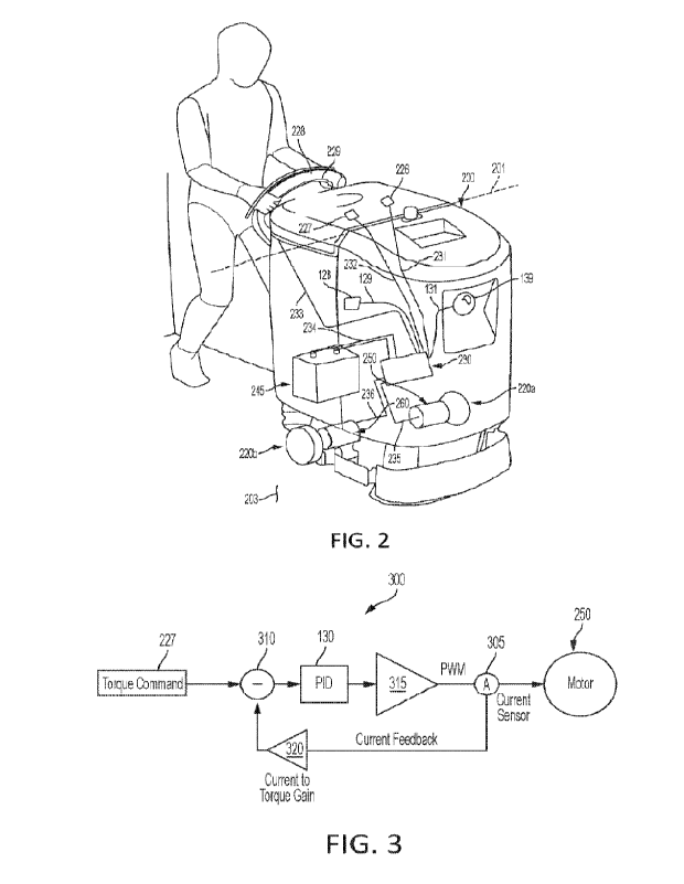
[0020] FIG. 2 illustrates the surface maintenance machine 200 in a partially
transparent,
perspective view so that various components of the surface maintenance machine
200 can be
seen. As noted previously, the machine 200 can include the grab handle 228,
the bail 229, and
various user operational controls, including the manual/autonomous mode user
input
mechanism 226 and the torque assist user input mechanism 227. In some
embodiments, one
or more of the grab handle 228, the bail 229, or the various user operational
controls
including the user input mechanisms 226 and 227 are positioned to the rear of
a transverse
centerline 201 of the machine.
[0021] When the machine 200 is operated in a manually driven mode, the grab
handle 228
and the bail 229 can be configured to cause the machine 200 to move along a
surface at
which a surface maintenance task is desired to be performed. To begin moving
the machine
200, the user can grasp the grab handle 228 and actuate the bail 229 to cause
a motive force
to be applied at the machine 200. For example, the bail 229 can be configured
to be actuated
via a user applying a pull force at the bail 229 (e.g., to move the bail 229
toward the grab
handle 228). A first actuation (e.g., a user applied pull force at the bail
229) of the bail 229
can activate application of the motive force at the machine 200, and a second
actuation (e.g.,
a user releasing, and thus terminating the pull force at, the bail 229) of the
bail 229 can
terminate application of the motive force at the machine 200. The grab handle
228 can
provide a surface at which a user of the machine 200 can grasp the machine 200
during
manual operation and apply desired user-originated forces. For instance, in
the manually
driven mode, the grab handle 228 can be grasped and used by a user to apply
user forces at
the machine 200 in different directions to cause the machine 200 to move
forward, move
rearward, turn in various directions or orientations on the underlying
surface, and change
orientation of the machine 200.
- 6 -
CA 03236454 2024- 4- 26
WO 2023/081302
PCT/US2022/048859
[0022] As illustrated, the machine 200 can include a controller 230. The
controller 230 can
be, for example, a programmable processor that is configured to execute non-
transitory
computer-readable instructions stored in a non-transitory memory component
(e.g., at the
controller 230). As one particular example, the controller 230 can include a
controller from
RoboteqTM serial number SBLM2360T. Execution of the non-transitory computer-
readable
instructions at the controller 230 can cause the machine 200 to perform one or
more various
features disclosed herein.
[0023] The bail 229 can be coupled to the controller 230, such as via a line
233. As noted, the
bail 229 be configured to be actuated to cause the machine 200 to move along a
surface at
which a surface maintenance task is desired to be performed. When actuated,
the bail 229 can
be configured to send a corresponding bail input signal to the controller 230
via the line 233.
The controller 230 can receive the bail input signal and, in response, output
a control signal to
one or more components at the machine 200 (e.g., one or both independently
controlled
motors) to cause such one or more components to take a corresponding action.
[0024] In some examples, the bail 229 can have more than two positions (e.g.,
pulling force
on bail and releasing force on bail) with each position corresponding to a
different operation
of the machine 200. For example, a first position of the bail can cause one or
more controllers
(e.g., 230) to operate in a torque assist mode which causes the machine to
move forward with
torque assist. Additionally, a second position of the bail can cause one or
more controllers
(e.g., 230) to disable a torque assist mode and cause the machine to stop
providing power to
motors. Further, a third position of the bail can cause one or more
controllers (e.g., 230) to
operate in a reverse torque assist mode which causes the machine to move
rearward with
torque assist.
[0025] The manual/autonomous mode user input mechanism 226 can be coupled to
the
controller 230, such as via a line 231. The manual/autonomous mode user input
mechanism
226 can receive one or more inputs thereat from the user of the machine 200
and, as a result,
send one or more corresponding input signals to the controller 230 via the
line 231. For
example, the manual/autonomous mode user input mechanism 226 can be
configured, when
actuated, to send a mode control signal to the controller 230 corresponding to
one of a
manual mode command and an autonomous mode command. For instance, a first
actuation of
the manual/autonomous mode user input mechanism 226 can cause the
manual/autonomous
mode user input mechanism 226 to send a manual mode control signal to the
controller 230,
and a second, different actuation of the manual/autonomous mode user input
mechanism 226
can cause the manual/autonomous mode user input mechanism 226 to send an
autonomous
- 7 -
CA 03236454 2024- 4- 26
WO 2023/081302
PCT/US2022/048859
mode control signal to the controller 230. As illustrative examples the first
actuation of the
manual/autonomous mode user input mechanism 226 can be a user providing a
manual mode
selection at the manual/autonomous mode user input mechanism 226 (e.g., via a
manual
mode button at the manual/autonomous mode user input mechanism 226) and the
second
actuation of the manual/autonomous mode user input mechanism 226 can be a user
providing
an autonomous mode selection at the manual/autonomous mode user input
mechanism 226
(e.g., via an autonomous mode button at the manual/autonomous mode user input
mechanism
226).
[0026] When the controller 230 receives the manual mode command from the
manual/autonomous mode user input mechanism 226, the controller 230 can, in
response,
execute non-transitory computer-readable instructions to cause the machine 200
to be
configured for operation in a manually driven mode. Likewise, when the
controller 230
receives the autonomous mode command from the manual/autonomous mode user
input
mechanism 226, the controller 230 can, in response, execute non-transitory
computer-
readable instructions to cause the machine 200 to be configured for operation
in an
autonomously driven mode.
[0027] When the surface maintenance machine 200 is configured for operation in
the
manually driven mode (e.g., in response to the controller 230 receiving the
mode control
signal corresponding to the manual mode command), the torque assist user input
mechanism
227 can be enabled so as to allow the torque assist user input mechanism 227
to send a torque
assist control signal to the controller 230. When so enabled, the torque
assist user input
mechanism 227 can be configured, when actuated, to send the torque assist
control signal to
the controller 230, and the torque assist control signal can correspond to a
torque assist on
command or a torque assist off command. When the torque assist on command is
executed by
the controller 230, the controller 230 can cause the surface maintenance
machine 200 to
execute a torque assisted power operation, as will be described further
herein. When the
torque assist off command is executed by the controller 230, the controller
230 can cause the
machine 200 to terminate execution of the torque assisted power operation.
Furthermore, in
some embodiments, when the machine 200 is configured for operation in the
autonomously
driven mode (e.g., in response to the controller 230 receiving the mode
control signal
corresponding to the autonomous mode command), the torque assist user input
mechanism
227 can be disabled so as to prevent the torque assist user input mechanism
227 from sending
a torque assist control signal to the controller 230. Of course, in some
embodiments when the
surface maintenance machine 200 is configured for operation in the manually
driven mode,
- 8 -
CA 03236454 2024- 4- 26
WO 2023/081302
PCT/US2022/048859
the torque assist user input mechanism 227 can be disabled and the controller
230 can operate
in velocity control mode in which the wheels are controlled to a particular
velocity setting,
forward or rearward, in response to the user moving, for instance, a bail
switch. In some
embodiments, when a torque assist mode is disabled, one or more controllers
(e.g., 230) can
either cause the machine to stop providing power to its motor(s) or cause the
machine to enter
a velocity control mode in which the velocity is set to zero.
[0028] In some embodiments, a vehicle controller can be interposed between the
bail 229 and
the controller 230. In similarity with the controller 230, the vehicle
controller can be, for
example, a programmable processor that is configured to execute non-transitory
computer-
readable instructions stored in a non-transitory memory component (e.g., at
the vehicle
controller). In operation, the vehicle controller can send, receive, and/or
relay signals with the
controller. For instance, the vehicle controller can relay signals from the
bail 229 and/or other
controls to the controller 230. Additionally or alternatively, the vehicle
controller can provide
one or more settings to the controller such as, for example, a torque output
setting.
[0029] The surface maintenance machine 200 can also include a power source
245, a first
wheel motor 250, a first driven wheel 220a, a second wheel motor 260, and a
second driven
wheel 220b. The power source 245 can be, for instance, one or more
rechargeable batteries,
and the power source 245 can be coupled to the controller 230, such as via one
or more lines
234. The power source 245 can be configured to provide operational power to
various (e.g.,
all) powered components at the machine 200. The first wheel motor 250 can be
coupled to
both the controller 230, such as via a line 235, and the first driven wheel
220a (e.g., via a first
mechanical rotor coupling). The first wheel motor 250 can be configured to
receive a first
driven wheel motive command from the controller 230 and, in response, generate
a
corresponding motive force and apply this corresponding motive force to the
first driven
wheel 220a. The second wheel motor 260 can be coupled to both the controller
230, such as
via a line 236, and the second driven wheel 220b (e.g., via a second
mechanical rotor
coupling). The second wheel motor 260 can be configured to receive a second
driven wheel
motive command from the controller 230 and, in response, generate a
corresponding motive
force and apply this corresponding motive force to the second driven wheel
220b. The first
wheel motor 250 and the second wheel motor 260 can be separate motors, and, in
one
specific embodiment, each of the first wheel motor 250 and the second wheel
motor 260 can
be a separate permanent magnet alternating current ("AC") motor. The first
wheel motor 250
can be operated independently of the second wheel motor 260. As such, the
controller 230
can send a motive command to only one of the motors 250, 260 and/or send
different motive
- 9 -
CA 03236454 2024- 4- 26
WO 2023/081302
PCT/US2022/048859
commands to the motors 250, 260 so as to cause the motors 250, 260 to
independently apply
specified, and in some instances different, motive forces to the driven wheels
220a, 220b.
[0030] In addition to the first driven wheel 220a and the second driven wheel
220b, the
machine 200 can include one or more additional wheels. For example, in some
embodiments,
the machine 200 can also include one or more non-driven (e.g., caster, idler)
wheels. In one
such example, the machine 200 can include the first and second driven wheels
220a, 220b
rear of a transverse centerline 201 of the machine 200 and include one or more
non-driven
(e.g., caster, idler) wheels forward of the transverse centerline 201 of the
machine 200. Such
an exemplary configuration where the first and second driven wheels 220a, 220b
are rear of
the transverse centerline 201 and one or more non-driven wheel(s) are forward
of the
transverse centerline 201 can be useful in reducing rear-swing of the machine
200 and, thus,
can configure the machine 200 to operate in relatively confined spaces. This
can be
particularly true in reducing rear-swing where the first and second driven
wheels 220a, 220b
are rear of, but proximate to, the transverse centerline 201. For instance,
the first and second
driven wheels 220a, 220b can rear of the transverse centerline 201 and within
three inches,
six inches, nine inches, twelve inches, fifteen inches, eighteen inches,
twenty one inches,
twenty four inches, twenty seven inches, or thirty inches of the transverse
centerline 201. In
another example, the machine 200 can include one or more non-driven wheel(s)
rear of the
transverse centerline 201 and the first and second driven wheels 220a, 220b
forward of the
transverse centerline 201. The transverse centerline 201 can, for instance, be
defined as a
plane extending perpendicular to a surface 203, on which the machine 200
operates, and
intersecting a longitudinal center of the machine 200. Forward of the
transverse centerline
201 can be in a forward direction of travel of the machine 200, and rearward
of the transverse
centerline 201 can be in a reverse direction of travel of the machine 200.
[0031] As noted, the machine 200 can be switched between manually driven and
autonomously driven modes (e.g., via actuation of the manual/autonomous mode
user input
mechanism 226).
[0032] To facilitate operation of the machine 200 in the autonomously driven
mode, the
machine 200 can include onboard one or more vision sensors 139. The vision
sensor 139 can
be coupled to the controller 130, such as via a line 131. The vision sensor
139 can be
configured to scan and detect features in the ambient environment of the
machine 200. In
some embodiments, the vision sensor 139 can include one or more of visible
light and/or
thermal (infrared) vision cameras, LIDAR sensors, laser beacons, ultrasound
sensors, and the
like to detect features of the environment (such as physical boundaries and
the like). In some
- 10 -
CA 03236454 2024- 4- 26
WO 2023/081302
PCT/US2022/048859
embodiments, the vision sensors 139 can be provided at various, spaced apart
locations on the
machine 200 (e.g., front, lateral sides, rear, and the like) so as to obtain
data corresponding to
areas at different locations around the machine 200 over a relatively wide
field of view. In
some particular embodiments, the field of view of the vision sensors 139 can
correspond to
an angle of between about 200 degrees and about 300 degrees, and a radius of
between about
50 feet and 150 feet. In one yet more particular embodiment, the field of view
of the vision
sensors 139 can be approximately 240 degrees and a radius of approximately 90
feet.
[0033] In certain embodiments, also to help facilitate operation of the
surface maintenance
machine 200 in the autonomously driven mode, the machine 200 can also include
a location
sensor 128. The location sensor 128 can be coupled to the controller 130, such
as via a line
129, and the location sensor 128 can include a wireless transceiver configured
to output a
wireless signal and receive a wireless signal. The location sensor 128 can
permit ascertaining
localization the machine 200, such as before, during, or after mapping of a
location at which
the machine 200 is to operate autonomously. In some embodiments, the location
sensor 128
can include a Global Positioning System ("GPS") sensor. Alternatively, or in
addition, the
location sensor 128 can include an inertial measurement unit (e.g., compass,
accelerometer,
gyroscope, magnetometer and the like). In addition, additional components such
as wireless
communication beacons (e.g., WiFi or Bluetooth) can be provided at the
location sensor 128
to improve accuracy of localization.
[0034] To further assist operation of the surface maintenance machine 200 in
the
autonomously driven mode, the machine 200 can include a mapping system. The
mapping
system can, for instance, be executed at the controller 130, such as via a
mapping processor
and mapping computer-executable instructions at the controller 130. The
mapping processor
can have one or more integrated circuits that can be in electrical
communication with an on-
board or a remote non-transitory memory component. The memory component can
store
mapping instructions in the form of a mapping software program that can be
executed by the
mapping processor to generate a map for use by the machine 200 to navigate a
location in the
autonomously drive mode. The mapping processor can be coupled (e.g., via the
controller
130) to the one or more vision sensors 139 and/or location sensor 128. For
instance, the
mapping processor can be coupled (e.g., via electrical circuits provided on
the machine 100)
to the vision sensors 139 and/or location sensor 128 such that data collected
by vision sensors
139 (e.g., electrical signals representative thereof) and/or the location
sensor 128 can be
transmitted to the mapping processor via the electrical circuits. The mapping
processor can
- 11 -
CA 03236454 2024- 4- 26
WO 2023/081302
PCT/US2022/048859
also send control signals to initiate data collection at the vision sensors
139 and/or the
location sensor 128.
[0035] In some examples, the mapping system can also include a visualization
processor. The
visualization processor can be provided as a part of the controller 130 (e.g.,
GPGPU
component at the controller 130) at the surface maintenance machine 200. The
visualization
processor can have one or more integrated circuits that can be in electrical
communication
with the mapping processor. Additionally, the visualization processor can be
in electrical
communication with the on-board and/or remote memory component. The memory can
store
computer-readable visualization instructions in the form of a visualization
software program
that can be executed by the visualization processor to generate a map of the
location at which
the machine 200 is to be autonomously operated. The controller 130 can then
execute the
generated map to provide control signals to the motors 250, 260.
100361 When in the autonomously driven mode, the surface maintenance machine
200 can be
configured to operate in a speed control mode (sometimes referred to as
velocity control
mode) for applying motive force, via the independently controlled motors 250,
260, to the
driven wheels 220a, 220b. For example, the controller 230 can execute a speed
control mode
program stored in a non-transitory memory component at the machine 200 in the
form of
computer-readable instructions executable by the controller 230 to cause the
controller 130 to
control movement of the machine 200 via the speed control mode.
[0037] When operated in the speed control mode, the controller 130 is provided
with a
predetermined set speed command, and the controller 130 is configured to
control the motors
250, 260 according to this predetermined set speed command (e.g., a
predetermined set speed
metric). In some examples, the predetermined set speed command can be provided
by the
user at the machine 200, and in other examples the predetermined set speed
command can be
provided by the machine 200 based on one or more preprogrammed instructions
(e.g., a
preprogramed default autonomous mode speed parameter). The controller 230 is
configured
to use this predetermined set speed command to output one or more first speed
command
signals, corresponding to the predetermined set speed command, to the first
wheel motor 250
and one or more second speed command signals, corresponding to the
predetermined set
speed command, to the second wheel motor 260. The first wheel motor 250 is
configured to
control its motor speed (and, thus, first driven wheel 220a speed) according
to the first speed
command signal from the controller 230. The second wheel motor 260 is
configured to
control its motor speed (and, thus, second driven wheel 220b speed) according
to the second
speed command signal from the controller 130. As such, when the machine 200 is
in in the
- 12 -
CA 03236454 2024- 4- 26
WO 2023/081302
PCT/US2022/048859
autonomously driven mode, the motors 250, 260 can be controlled independently
by the
controller 130 to operate at a motor speed corresponding to the predetermined
set speed
command.
[0038] For example, the speed control mode can be configured to control the
speed of each
motor 250, 260 via the amount of voltage provided to the respective motors
250, 260. As
such, to maintain the predetermined set speed command for each motor 250, 260
as a load at
each of the motors 250, 260 varies during operation in the autonomously driven
mode, the
speed of the respective motors 250, 260 can be accelerated or decelerated as
applicable to the
particular instantaneous applied load at the respective motors 250, 260. As
one such example,
to maintain the predetermined set speed command for the first wheel motor 250
when the
first wheel motor 250 experiences a load acting to decelerate the speed of the
first wheel
motor 250 (e.g., machine 200 traversing an inclined surface), the controller
130 can output
the first speed command signal, corresponding to the predetermined set speed
command, to
cause the speed of the first wheel motor 250 to increase and, thereby,
accelerate the speed of
the first wheel motor 250 until the speed of the first wheel motor 250 is
increased to the
predetermined set speed command. As another similar example, to maintain the
predetermined set speed command for the first wheel motor 250 when the first
wheel motor
250 experiences a load acting to accelerate the speed of the first wheel motor
250 (e.g.,
machine 200 traversing an declined surface), the controller 130 can output the
first speed
command signal, corresponding to the predetermined set speed command, to cause
the speed
of first wheel motor 250 to decrease and, thereby, decelerate the speed of the
first wheel
motor 250 until the speed of the first wheel motor 250 is reduced to the
predetermined set
speed command. The second wheel motor 260 can be controlled in the same, but
independent, manner in the speed control mode via the second speed command
signal from
the controller 130. Because the first wheel motor 250 and the second wheel
motor 260 can be
controlled independently by the controller 130, the rate of rotation of the
first driven wheel
220a can be controlled, in certain instances (e.g., to turn the machine 200 in
the
autonomously driven mode) to be a different than the rate of rotation of the
second driven
wheel 220b.
100391 As noted, the speed control mode can be configured to control the speed
of each
motor 250, 260 via a controlled amount of voltage provided to the respective,
independently
controlled motors 250, 260. As one such example, the speed control mode can be
executed at
the machine 200, in the autonomously driven mode, using a pulse width
modulated signal
with a specific duty cycle that is increased or decreased to increase or
decrease the rate of
- 13 -
CA 03236454 2024- 4- 26
WO 2023/081302
PCT/US2022/048859
rotation of the respective driven wheel 220a, 220b. In addition, each of the
first wheel motor
250 and the second wheel motor 260 can provide feedback to the controller 130
indicating
the current rate of rotation of the respective drive wheel 220a, 220b. This
feedback from each
motor 250, 260 can be used by the controller 130 to adjust the respective
voltage provided to
each motor 250, 260 (e.g., adjusting the voltage provided to one motor 250 if
one wheel 220a
is rotating faster or slower than expected that corresponding to the
predetermined set speed
command for that motor 250).
[0040] When in the manually drive mode, the torque assist user input mechanism
227 can be
enabled. When enabled, the torque assist user input mechanism 227 can be
configured, when
actuated, to send a first torque assist control signal to the controller 130
corresponding to a
torque assist on command. When the torque assist control signal, corresponding
to the torque
assist on command, is executed by the controller 130, the controller 130 can
cause the
machine 200 to execute a torque assisted power operation. On the other hand,
the torque
assist user input mechanism 227 can also be configured to be actuated (e.g., a
second
actuation different than the actuation causing the torque assist on command)
to cause a
second torque assist control signal to be sent from the controller 130 to the
motors 250, 260
corresponding to a torque assist off command. When the torque assist control
signal,
corresponding to the torque assist off command, is executed by the controller
130, the
controller 130 can cause the machine 200 to terminate a torque assisted power
operation.
[0041] When enabled and upon actuation of the torque assist user input
mechanism 227, the
surface maintenance machine 200 can be configured to operate in a torque
control mode for
applying motive force to the driven wheels 220a, 220b. For example, the
controller 130 can
execute a torque control mode program stored in a non-transitory memory
component at the
machine 200 in the form of computer-readable instructions executable by the
controller 130
to cause the controller 130 to control movement of the machine 200 via the
torque control
mode. The torque control mode, implemented when the machine 200 is in the
manually drive
mode, can be different than the speed control mode, implemented when the
machine 200 is in
the autonomously drive mode.
[0042] As noted, when in the manually driven mode, the surface maintenance
machine 200
can be configured to operate in a torque control mode for applying motive
force, via the
independently controlled motors 250, 260, to the driven wheels 220a, 220b. For
example, the
controller 230 can execute the torque control mode program to cause the
controller 230 to
control movement of the machine 200 via the torque control mode. When operated
in the
torque control mode, the controller 230 is provided with a predetermined set
torque
- 14 -
CA 03236454 2024- 4- 26
WO 2023/081302
PCT/US2022/048859
command, and the controller 230 is configured to control the motors 250, 260
according to
this predetermined set torque command (a predetermined set torque metric). In
some
examples, the predetermined set torque command can be provided by the user at
the machine
200 (e.g., user selection of one of at least a preprogramed manual mode first
torque parameter
and a preprogramed manual mode second torque parameter different than the
preprogramed
manual mode first torque parameter), and in other examples the predetermined
set torque
command can be provided by the machine 200 based on one or more preprogrammed
instructions (e.g., a preprogramed default manual mode first torque
parameter). The
controller 230 is configured to use this predetermined set torque command to
output one or
more first torque command signals, corresponding to the predetermined set
torque command,
to the first wheel motor 250 and one or more second torque command signals,
corresponding
to the predetermined set torque command, to the second wheel motor 260. The
first wheel
motor 250 is configured to control its motor torque according to the first
torque command
signal from the controller 130. And, the second wheel motor 260 is configured
to control its
motor torque according to the second torque command signal from the controller
230 As
such, when the machine 200 is in in the manually driven mode, the motors 250,
260 can be
controlled independently by the controller 230 to operate at motor torque
corresponding to
the predetermined set torque command.
[0043] For example, the torque control mode can be configured to control the
torque output
of each motor 250, 260 via the amount of power (e.g., current and/or voltage)
delivered to the
respective motors 250, 260. As such, to maintain the predetermined set torque
command for
each motor 250, 260 as a load at each of the motors 250, 260 varies during
operation in the
manually driven mode, the torque of the respective motors 250, 260 can be
increased or
decreased as applicable to the particular instantaneous applied load at the
respective motors
250, 260. As one such example, to maintain the predetermined torque command
for the first
wheel motor 250 when the first wheel motor 250 experiences an increase in load
acting on
the first wheel motor 250 (e.g., machine 200 traversing an inclined surface; a
user pulling, or
otherwise applying a force that restricts movement of, the machine 200), the
controller 130
can output the first torque command signal, corresponding to the predetermined
set torque
command, to cause the torque of the first wheel motor 250 to decrease and,
thereby, decrease
the torque applied at the first driven wheel 220a, via the first wheel motor
250, until the
torque of the first wheel motor 250 is decreased to the predetermined set
torque command. In
another similar example, to maintain the predetermined set torque command for
the first
wheel motor 250 when the first wheel motor 250 experiences a decreased load
acting on the
- 15 -
CA 03236454 2024- 4- 26
WO 2023/081302
PCT/US2022/048859
first wheel motor 250 (e.g., machine 200 traversing a declined surface; a user
pushing, or
otherwise applying a force that increases movement of the machine 200), the
controller 230
can output the first torque command signal, corresponding to the predetermined
set torque
command, to cause the torque of the first wheel motor 250 to increase and,
thereby, increase
the torque applied at the first driven wheel 220a, via the first wheel motor
250, until the
torque of the first wheel motor 250 is increased to the predetermined set
torque command.
The second wheel motor 260 can be controlled in the same, but independent,
manner in the
torque control mode via the second torque command signal from the controller
130. Because
the first wheel motor 250 and the second wheel motor 260 can be controlled
independently
by the controller 230, the rate of rotation of the first driven wheel 220a can
be controlled, in
certain instances (e.g., to help turn the machine 200 along with user applied
turn force in the
manually driven mode) to be a different than the rate of rotation of the
second driven wheel
220b.
[0044] FIG. 3 illustrates a schematic block diagram of an exemplary embodiment
of circuitry
300 for executing a closed-loop torque control mode. The circuitry can include
a comparator
stage 310, proportional-integral-derivative controller (PID) controller 130, a
pulse width
modulation (PWM) stage 315, a current sensor 305, and a current to torque gain
stage 320.
[0045] In a general example operation, a torque command 227, which can be a
predetermined
set torque command received from an operator via a bail, is received by the
circuitry and goes
through the comparator stage 310 to the PID controller 130 and the PWM stage
315. The PID
controller, in conjunction with the PWM stage, can interpret and adjust the
torque command
into a signal having a voltage and current level which is applied to the motor
250. In some
examples, the PID controller 130 and the PWM stage can modulate a voltage
applied to the
motor 250 to effectuate a change in the corresponding current applied to the
motor 250. As
discussed above, adjusting the current applied to the motor 250 can adjust the
torque applied
at a corresponding driven wheel. The current applied to the motor 250 can then
be measured
by the current sensor 305 and feed back to the comparator 310 after passing
through the
current to torque gain stage 320 to be converted to a torque level. In some
examples, though,
the current sensor and the current to torque gain stage are replaced by a
torque sensor. The
torque sensor can be coupled to the motor and can directly measure a torque
(e.g., via an
internal strain gauge). Further, the torque sensor can output a torque level
to the comparator
stage 310.
[0046] The comparator 310 can then compare the torque level from the current
feedback,
which represents the torque the motor is actively applying to a driven wheel,
with the torque
- 16 -
CA 03236454 2024- 4- 26
WO 2023/081302
PCT/US2022/048859
command 227, which represents the desired torque. If the torque level from the
current
feedback is less than the torque command level, the comparator 310 outputs a
signal which
the PID controller 130 and the PWM stage 315 use to increase the current
applied to the
motor. Alternatively, if the torque level from the current feedback is greater
than the torque
command level, the comparator 310 outputs a signal which the PID controller
130 and the
PWM stage 315 use to decrease the current applied to the motor. However, if
the torque level
from the current feedback is equal to the torque command level, the comparator
outputs a
signal which the PID controller 130 and the PWM stage 315 use to maintain the
same current
applied to the motor. Thus, the circuitry 300 can enable effective control of
torque applied by
the motor to a driven wheel, ensuring the torque command corresponds closely
with the
actual torque applied by the motor to a driven wheel.
[0047] As discussed above, in operation, the motor 250 can experience an
increase or
decrease in external loads. For example, the motor 250 can experience an
increased load
acting on it when the machine traverses an inclined surface; a user pulling,
or otherwise
applying a force that restricts movement of the machine. In such an example,
the increased
load on the motor 250 can increase the current of the motor and increase the
torque the motor
250 applies to a driven wheel. In response to this increased current, the
circuitry 300 that
executes the closed-loop torque control can attempt to decrease the torque
applied by the
motor 250 to the driven wheel by decreasing the current applied to the motor
250. In such an
example, the current sensor 305 can measure the increased current of the motor
250 and
feedback the current to the comparator 310 through the current to torque gain
stage 320. After
the current is converted to a torque via the current to torque gain stage 320,
the comparator
310 can determine that the level of torque from the torque command is less
than the level of
feedback torque. In response, the PID controller 130 and the PWM stage 315 can
use the
resulting signal received from the comparator to decrease the voltage applied
to the motor,
thereby decreasing the current and the torque that the motor applies to the
driven wheel. In
such an operation, if the increased load is due to a user pulling or otherwise
applying a force
that restricts movement of the machine, the user is assisted in that the
movement of the
machine is correspondingly decreased.
100481 In an alternative example operation, the motor 250 can experience a
decreased load
acting on it when the machine traverses a declined surface; a user pushing, or
otherwise
applying a force that increases movement of the machine. In such an example,
the decreased
load on the motor 250 can decrease the current of the motor and decrease the
torque the
motor 250 applies to a driven wheel. In response to this decreased current,
the circuitry 300
- 17 -
CA 03236454 2024- 4- 26
WO 2023/081302
PCT/US2022/048859
that executes the closed-loop torque control can attempt to increase the
torque applied by the
motor 250 to the driven wheel by increasing the current applied to the motor
250. In such an
example, the current sensor 305 can measure the decreased current of the motor
250 and feed
back the current to the comparator 310 through the current to torque gain
stage 320. After the
current is converted to a torque via the current to torque gain stage 320, the
comparator 310
can determine that the level of torque from the torque command is greater than
the level of
feedback torque. In response, the PID controller 130 and the PWM stage 315 can
use the
resulting signal received from the comparator to increase the voltage applied
to the motor,
thereby increasing the current and the torque that the motor applies to the
driven wheel. In
such an operation, if the decreased load is due to a user pushing or otherwise
applying a force
that increases movement of the machine, the user is assisted in that the
movement of the
machine is correspondingly increased.
100491 While the circuitry 300 is shown and described as comprising discrete
components
and operating using analog signals (e.g., a current signal), a person of
ordinary skill will
appreciate the circuitry is not so limited. For instance, in some embodiments,
the circuitry
300 can comprise integrated circuits (ICs), which can be any combination of
discrete
components, and the circuitry 300 can use digital signals to communicate. In
some
embodiments, the circuitry 300 can comprise a combination of discrete
components and non-
discrete components (e.g., ICs) and can use both digital signals and analog
signals to
communicate. For instance, the current sensor 305 can communicate current in
the form of a
digital signal while a signal applied to the motor 250 is an analog signal.
[0050] As discussed above and with reference to FIG. 2 and FIG. 3, the surface
maintenance
machine 200 can be configured to operate in a torque control mode which is
used to control
the torque output of a first motor 250 and a second motor 260 via the amount
of current
provided to the respective motors 250, 260. In such embodiments, the
controller 230 controls
the first motor 250 and the second motor 260 via the torque control mode and
can provide a
selected torque output setting to each of the first motor 250 and the second
motor 260 (e.g.,
via user input). Further, the first motor 250 and the second motor 260 can be
controlled by
two separate control loops that apply the torque control mode to them. For
example, the
example control loop/logic of FIG. 3 can be duplicated to control the first
motor 250 and the
second motor 260.
[0051] Additionally, as the load at each of the motors 250, 260 varies during
operation in the
torque control mode, the torque of the respective motors 250, 260 can be
increased or
decreased as applicable to the particular instantaneous applied load at the
respective motors
- 18 -
CA 03236454 2024- 4- 26
WO 2023/081302
PCT/US2022/048859
250, 260. In an example application of the torque control mode, a user can
provide an input to
the controller 230 (e.g., via a grab handle 228) to turn the surface
maintenance machine 200
leftward when the machine is traversing in a forward direction. In such an
example, the user
can exert a force on the machine via the grab handle to restrict movement of
the leftward side
of the machine. This restriction of movement of the leftward side of the
machine can cause an
increase in the load of the first motor 250 (e.g., a leftward motor) which can
increase the
current of the first motor and increase a torque that the first motor applies
250 to the first
driven wheel 220a. The controller 230 can sense this increase in torque via
the corresponding
current sensor (e.g., 305) and can decrease the power delivered to the first
motor 250 to
decrease the torque. In some examples, decreasing the power delivered to the
first motor
comprises decreasing a current applied to the first motor. Additionally or
alternatively, in
some examples, decreasing the power delivered to the first motor comprises
decreasing a
voltage applied to the first motor.
[0052] Continuing with the example, the user can exert a force on the machine
(e.g., via the
grab handle) to increase movement of the rightward side of the machine. This
increase of
movement of the rightward side of the machine can cause a decrease in the load
of the second
motor 260 (e.g., a rightward motor) which can decrease the current of the
second motor and
decrease a torque that the second motor 260 applies to the second driven wheel
220b. The
controller 230 can sense this decrease in torque via the corresponding current
sensor (e.g.,
305) and can increase the power delivered to the second motor 260 to increase
the torque. In
some examples, increasing the power delivered to the second motor comprises
increasing a
current applied to the second motor. Additionally or alternatively, in some
examples,
increasing the power delivered to the second motor comprises increasing a
voltage applied to
the second motor. Thus, the controller 230 can aid a user in turning the
surface maintenance
machine 200 leftward by decreasing the torque of the first motor 250 and
increasing the
torque of the second motor 260. In a similar manner, the controller can aid a
user in turning
the surface maintenance machine 200 rightward by increasing the torque of the
first motor
250 and decreasing the torque of the second motor 260.
[0053] Moving to FIG. 4, FIG. 4 is a partially transparent, schematic
perspective view of an
example surface maintenance machine 400 having a single motor 470 and a
transaxle 472.
The surface maintenance machine 400 includes a motor controller 430 and a
motor 470 that
are powered by a battery 445. The surface maintenance machine 400 further
includes a left
drive wheel 420a and a right drive wheel 420b that are connected to the motor
470 via a
transaxle 472. The transaxle 472 comprises an axel 474 and a differential 476
that enables the
- 19 -
CA 03236454 2024- 4- 26
WO 2023/081302
PCT/US2022/048859
connected left drive wheel 420a and right drive wheel 420b to turn at
different speeds. The
transaxle 472 connects to the motor 470 via its differential 476 which enable
the machine 400
to operate with a single motor 470. In comparison to the embodiment of FIG. 2,
the
embodiment of FIG. 4 does not require two motors which can decrease cost and
energy use,
enabling a longer runtime of the machine. However, the embodiment of FIG. 2
can have
increased maneuverability in comparison to the embodiment of FIG. 4 such as
being able to
make a zero turn.
[0054] Moving to FIG. 5, FIG. 5 is a flowchart of an example method of
providing a torque
assist mode to a surface maintenance machine. The method can start with an
optional step
500, receiving a control input to enable a specified mode of operation and
optionally a setting
of the mode of operation. In some embodiments, a controller (e.g., 230) can
receive a control
input to enable a specified mode of operation. In some such embodiments, the
controller can
receive a user input from a bail or other user input device to enable the
machine to operate in
a manual mode, an autonomous mode, a torque assist mode, a speed/velocity
control mode, a
combination of modes, or other modes of operation. Once the specified mode of
operation is
enabled, a setting of the specified mode of operation can be enabled. For
example, the
method can include setting of a specific amount of torque output for one or
more motors of
the machine.
[0055] Next, in step 510, the method includes receiving a force urging the
machine to change
orientation toward a direction of travel. In some examples, the force urging
the machine to
change orientation is from a user that imparts a force on a grab handle of the
machine. The
urging of the machine to change orientation toward a direction of travel can
include urging
the machine to turn left or right, move forward or backward, or move a
combination of
directions. In general, the urging of the machine attempts to change the
current orientation
and/or position of the machine.
100561 Continuing with step 520, the method includes sensing a parameter
indicative of an
amount of motor load on a first motor and an amount of motor load on a second
motor. As
discussed elsewhere herein, the parameter indicative of an amount of motor
load can include
a current or a torque of a motor and can be sensed by a current sensor or a
torque sensor
respectively.
100571 Further, in step 530, the method includes controlling a power delivered
to the first
motor and a power delivered to the second motor to maintain a torque output
setting. As
discussed elsewhere herein with respect to FIG. 2 and FIG. 3, in some
examples, a controller
(e.g., 230) performs step 530 and can control an amount of power delivered to
a motor via
- 20 -
CA 03236454 2024- 4- 26
WO 2023/081302
PCT/US2022/048859
controlling an amount of current and/or voltage applied to the motor. Further,
in such
embodiments, the controller can ensure that a torque output setting is
maintained at the first
motor and second motor by controlling the power delivered to the first motor
and the power
delivered to the second motor.
[0058] After controlling the power as describe in step 530, the method can
either return to
step 500 or 510. In general, the method returns to step 510 unless the mode of
operation
changes. For example, a user can initially engage a torque control mode with a
specific
torque setting which is received in step 500. Next, the user can impart a
force to the machine
to change its orientation (e.g., turn left) which is received in step 510.
Further, a current
sensor, torque sensor, or other sensor can sense an amount of motor load on
the first motor
and second motor which can then be used by a controller to control a power
delivered to the
first motor and second motor to maintain a torque output setting. Next, unless
a user selects a
different mode of operation or disables the current mode of operation, which
would result in
the method continuing with step 500, the user will again impart a force to the
machine to
change its orientation and the method repeats with step 510.
100591 In some examples, the method of FIG. 5 is performed by a system such as
described
with respect to FIG. 2 and FIG. 3. However, a person having ordinary skill in
the art will
appreciate that the method of FIG. 5 is not limited by the system and
structure of FIG. 2 and
FIG. 3.
[0060] While embodiments of the present disclosure are described as being
included, and
executed, by a surface maintenance machine, the embodiments are not limited to
surface
maintenance machines. For instance, in some embodiments, the torque control
described
elsewhere herein can be used by devices comprising motors including motor
vehicles, lawn
mowers, carts, scooters, etc.
100611 Various non-limiting exemplary embodiments have been described. It will
be
appreciated that suitable alternatives are possible without departing from the
scope of the
examples described herein.
- 21 -
CA 03236454 2024- 4- 26