Note: Descriptions are shown in the official language in which they were submitted.
WO 2023/076720
PCT/US2022/048554
CONDUIT FITTINGS FOR CONDUIT AND CABLE INSTALLATIONS
Cross-Reference to Related Applications
[0001] This application claims the benefit of U.S. Provisional Patent
Application No.
63/274.241, filed on November 1, 2021, the disclosure of which is hereby
incorporated by
reference in its entirety.
BACKGROUND OF THE INVENTION
Field of the Invention
[0002] The present disclosure relates to conduit bodies for conduit and cable
installations,
and more particularly to conduit bodies with features to ease cable routing
and pulling, and to
conduit bodies with features to facilitate drainage.
Description of Related Art
[0003] Conduit is a well-known protective covering and routing path for use
with electrical
wire and cable in both industrial, commercial, and residential applications.
Electrical
installations utilizing conduit typically include lengths of conduit connected
by various types
of fittings. Conduit is offered in a variety of metal, plastic, and composite
materials, and is
selected based on the needs of a particular application. A multitude of
governing bodies
promulgate regulations requiring that conduit used in specific applications
meets certain
minimum requirements. For example, in certain applications, metal conduit and
conduit
fittings must maintain a minimum level of sterility to prevent corrosion,
contamination and
bacteria growth thereon.
[0004] Cables and/or wires are installed in the conduit by pulling the
cables/wires through
the run of connected conduits and fittings. Significant force may be required
to pull the
wire/cable through the conduit run, depending on the inner diameter of the
conduit, the number
and size of wires, the number and size of bends in the conduit, and the use of
pulling lubricant.
If the required pulling force is too great to practically pull the cable/wire
through the entire run
of conduit, conduit bodies with access covers may be installed in the conduit
run to allow the
cable/wire to be pulled through the conduit run in multiple sections. Some
industry regulations
require or recommend such conduit bodies be installed after a predetermined
number of bends
in the conduit run. To install the cable/wire, a leading end of the cable/wire
is pulled through
the conduit run until the leading end enters the conduit body. A desired
amount of the
cable/wire is pulled out of the access opening of the conduit body, and then
the leading end of
1
CA 03236640 2024- 4- 29
WO 2023/076720
PCT/US2022/048554
the cable/wire is reinserted into the conduit body and pulled through the next
section of the
conduit run.
[0005] Conventional conduit bodies, while allowing the cable/wire
to be pulled through in
sections, still have limitations. First, the cable/wire tends to drag along
the inner wall of the
conduit fitting when pulled taut, which causes friction. Second, when the
leading end of the
cable/wire is reinserted into the conduit body and the slack cable is pulled
through the next
section of conduit, the cable/wire is forced into a tight bend as the last of
the slack re-enters the
conduit body. A significant amount of force may be required to pull this last
bit of slack cable
into the conduit body. In some instances, installers will address these issues
by simply using a
larger trade size conduit than would otherwise be required in order to provide
additional room
for placement and bending of the cable/wire. While this may ostensibly reduce
the pull force
required for installation, the use of lager fittings, conduit bodies, and
conduit runs adds expense
and size that would otherwise not be required by regulatory codes/standards.
[0006] Conventional conduit bodies also tend to become collection points for
water that
inadvertently enters the conduit run. The presence of water near or in contact
with the
cable/wire may be dangerous and run afoul of industry regulations.
Additionally, water may
corrode various components of the conduit, fittings, and/or cable/wire.
[0007] In view of the foregoing, there exists a need for conduit bodies
designed for easier
pulling of cable, and for conduit bodies with features for extracting water.
SUMMARY
[0008] Embodiments of the present disclosure are directed to conduit bodies
for use in
conduit and cable installations. Some embodiments of the present disclosure
are directed to a
conduit body including a sidewall defining an internal chamber and at least
two ports providing
access to the internal chamber, and a cover connectable to the sidewall to
enclose the internal
chamber. The sidewall defines a first surface section adjacent one of the at
least two ports, a
second surface section adjacent another of the at least two ports, and a
radiused transition
section connecting the first surface section and the second surface section
and configured for
reducing frictional drag of a cable pulled though the internal chamber. The
first surface section
is spaced apart from the second surface section to increase a volume of the
internal chamber.
[0009] In some embodiments, a distance between the first surface section and
the second
surface section dictates a bend radius of the cable in the internal chamber.
2
CA 03236640 2024- 4- 29
WO 2023/076720
PCT/US2022/048554
[0010] In some embodiments, the conduit body further includes a gasket between
the
sidewall and the cover.
[0011] In some embodiments, the at least two ports are arranged at
approximately 900
relative to one another.
[0012] In some embodiments, the cover is located on an opposite side of the
internal
chamber relative to one of the at least two ports.
[0013] In some embodiments, the cover is located on a side of the conduit body
parallel to a
plane extending through the at least two ports.
[0014] In some embodiments, the conduit body further includes a drain port in
fluid
communication with the internal chamber.
[0015] In some embodiments, the conduit body further includes a drain fitting
connected to
the drain port.
[0016] In some embodiments, the drain fitting includes a plug or a valve.
[0017] In some embodiments, the drain port is oriented approximately
perpendicular to one
of the at least two ports.
[0018] In some embodiments, the drain port is located at a lowest point of the
internal
chamber.
[0019] In some embodiments, the cover is connectable to the sidewall by three
fasteners.
[0020] In some embodiments, each of the three fasteners is adjacent to one of
the ports.
[0021] In some embodiments, the at least two ports include three ports.
[0022] In some embodiments, two of the three ports are coaxial to one another,
and a third
of the three ports extends at approximately 90 relative to the other two
ports.
[0023] Other embodiments of the present disclosure are directed to a conduit
body including
a sidewall defining an internal chamber and at least two ports providing
access to the internal
chamber, a cover connectable to the sidewall to enclose the internal chamber,
a drain port in
fluid communication with the internal chamber.
[0024] In some embodiments, the conduit body further includes a drain fitting
connected to
the drain port.
[0025] In some embodiments, the drain fitting includes a plug or a valve.
[0026] In some embodiments, the drain port is oriented approximately
perpendicular to one
of the at least two ports.
[0027] In some embodiments, the drain port is located at a lowest point of the
internal
chamber.
3
CA 03236640 2024- 4- 29
WO 2023/076720
PCT/US2022/048554
[0028] Further details and advantages of the various examples described in
detail herein will
become clear upon reviewing the following detailed description of the various
examples in
conjunction with the accompanying drawing figures.
BRIEF DESCRIPTION OF THE DRAWINGS
[0029] The above-mentioned and other features and advantages of this
disclosure, and the
manner of attaining them, will become more apparent and the disclosure itself
will be better
understood by reference to the following descriptions of embodiments of the
disclosure taken
in conjunction with the accompanying drawings, wherein:
[0030] FIG. 1 is a perspective view of a conduit body in accordance with an
embodiment of
the present disclosure;
[0031] FIG. 2 is a perspective view of the conduit body of FIG. 1, with a
cover thereof
removed for clarity;
[0032] FIG. 3 is a top view of the conduit body of FIG. 1, with the cover
thereof removed
for clarity;
[0033] FIG. 4 is a cross-sectional view of the conduit body of FIG. 1, taken
along line A-A
of FIG. 3;
[0034] FIG. 5 is an exploded perspective view of a conduit body in accordance
with an
embodiment of the present disclosure;
[0035] FIG. 6 is a top view of the conduit body of FIG. 5, with a cover
thereof removed for
clarity;
[0036] FIG. 7 is a perspective view of a conduit body in accordance with an
embodiment of
the present disclosure;
[0037] FIG. 8 is a perspective view of the conduit body of FIG. 7, with a
cover thereof
removed for clarity;
[0038] FIG. 9 is a side view of the conduit body of FIG. 7, with the cover
thereof removed
for clarity;
[0039] FIG. 10 is a perspective view of a conduit body in accordance with an
embodiment
of the present disclosure;
[0040] FIG. 11 is an exploded perspective view of the conduit body of FIG. 10;
[0041] FIG. 12 is a cross-sectional view of the conduit body of FIG. 10, taken
along line B-
B of FIG. 10;
[0042] FIG. 13 is a perspective view of a conduit body in accordance with an
embodiment
of the present disclosure;
4
CA 03236640 2024- 4- 29
WO 2023/076720
PCT/US2022/048554
[0043] FIG. 14 is a perspective view of the conduit body of FIG. 13, with a
cover thereof
removed for clarity;
[0044] FIG. 15 is a side view of the conduit body of FIG. 13, with a cover
thereof removed
for clarity; and
[0045] FIG. 16 is a cross-sectional view of the conduit body of FIG. 13, taken
along line C-
C of FIG. 15.
[0046] Corresponding reference characters indicate corresponding parts
throughout the
several views. The exemplifications set out herein illustrate exemplary
embodiments of the
disclosure, and such exemplifications are not to be construed as limiting the
scope of the
disclosure in any manner.
DETAILED DESCRIPTION
[0047] The following description is provided to enable those skilled in the
art to make and
use the described aspects contemplated for carrying out the disclosure.
Various modifications,
equivalents, variations, and alternatives, however, will remain readily
apparent to those skilled
in the art. Any and all such modifications, variations, equivalents, and
alternatives are intended
to fall within the spirit and scope of the present disclosure.
[0048] For purposes of the description hereinafter, the terms "upper",
"lower", "right",
"left", "vertical", "horizontal", "top-, "bottom", "lateral", "longitudinal",
and derivatives
thereof shall relate to the invention as it is oriented in the drawing
figures. However, it is to be
understood that the invention may assume various alternative variations,
except where
expressly specified to the contrary. It is also to be understood that the
specific devices
illustrated in the attached drawings, and described in the following
specification, are simply
exemplary aspects of the invention. Hence, specific dimensions and other
physical
characteristics related to the aspects disclosed herein are not to be
considered as limiting.
[0049] All numbers used in the specification and claims arc to be understood
as being
modified in all instances by the term "about". The terms -approximately",
"about", and
"substantially" mean a range of plus or minus ten percent of the stated value.
Further, the term
"substantially equal" and like terms mean that the compared values or
dimensions are within a
range of plus or minus ten percent of one another.
[0050] The terms "first", "second", and the like are not intended to refer to
any particular
order or chronology, but refer to different conditions, properties, or
elements.
[0051] As used herein, "at least one of' is synonymous with "one or more of'.
For example,
the phrase "at least one of A, B, and C- means any one of A, B, or C, or any
combination of
CA 03236640 2024- 4- 29
WO 2023/076720
PCT/US2022/048554
any two or more of A, B, or C. For example, "at least one of A, B, and C"
includes one or
more of A alone; or one or more of B alone; or one or more of C alone; or one
or more of A
and one or more of B; or one or more of A and one or more of C; or one or more
of B and one
or more of C; or one or more of all of A, B, and C.
[0052] Embodiments of the present disclosure are generally directed to conduit
bodies with
features to ease the installation of cable through the conduit body and other
sections of a conduit
run. In some embodiments, the conduit bodies include an internal chamber
having a shape and
volume configured to ease cable installation. In some embodiments, the conduit
bodies include
relatively large edge radiuses to facilitate smooth pulling of cable.
[0053] Additionally, embodiments of the present disclosure are directed to
conduit bodies
including features for draining water accumulated in the conduit bodies or
other portions of the
conduit run.
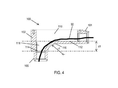
[0054] Referring now to FIGS. 1-4, a conduit body 100 is illustrated in
accordance with an
embodiment of the present disclosure. The conduit body 100 includes a sidewall
102 defining
an internal chamber 110 which houses one or more cables 90 (see FIG. 4). The
sidewall 102
further defines (or is connected to) two ports 104, 106, which provide access
to the internal
chamber 110 for the cable 90 to be installed. The ports 104, 106 in the
illustrated embodiment
are arranged at approximately 90' relative to one another, though in other
embodiments the
ports 104, 106 could be provided at another angle or could be arranged
coaxially relative to
one another. Each of the ports 104. 106 is configured to receive a conduit
through which cable
90 (see FIG. 4) is fed into or out of the internal chamber 110. Each of the
ports 104, 106 may
include an NPT thread or other industry standard interface for connecting to
the conduit.
[0055] The conduit body 100 further includes a cover 120 which removably
connects to the
sidewall 102 via fasteners 122, e.g. screws, received by threaded holes 124 in
the sidewall 102.
The cover 120, along with the sidewall 102, encloses the internal chamber 110.
The cover 120
is located on an opposite side of the internal chamber 110 relative to the
port 106. In some
embodiments, a gasket may be provided between the sidewall 102 and the cover
120 to provide
a fluid-tight and/or air-tight seal isolating the internal chamber 110 from
the external
atmosphere surrounding the conduit body 100.
[0056] With continued reference to FIGS. 3 and 4, within the internal chamber
110, the
sidewall 102 defines a first surface section 112 adjacent the port 104 and a
second surface
section 114 adjacent the port 106. The first surface section 112 and the
second surface section
114 are arranged on different planes spaced apart by a distance dl. In some
embodiments, the
distance dl may be in a range from approximately 1 inch to approximately 2
inches, and in
6
CA 03236640 2024- 4- 29
WO 2023/076720
PCT/US2022/048554
certain embodiments, dl may be approximately 1.39 inches. The first surface
section 112 and
the second surface section 114 are connected by a radiused transition section
116. In some
embodiments, a radius rl of the radiused transition section 116 may be in a
range from
approximately 1 inch to approximately 2 inches, and in certain embodiments, rl
may be
approximately 1.19 inches. Note that the exemplary dimensions of dl, d2, d3,
d4, rl, r2, r3,
and r4 provided herein are reflective only of certain embodiments of the
conduit body given a
particular trade size. Other embodiments, particularly embodiments for other
trade sizes of
conduit, may be outside of the disclosed measurements and ranges. A portion
118 of the
internal chamber 110 between the planes of the first and second surface
sections 112, 114
provides additional volume in which the cable 90 can reside.
[0057] The cable 90, when pulled through the conduit body 100, generally drags
along the
radiused transition section 116, and the cable 90 is forced to bend in order
to pass through both
ports 104, 106. The force required to bend the cable 90 and the frictional
force of the cable 90
against the radiused transition section 116 form a component of the pull force
required to install
the cable 90. By increasing the distance dl, and consequently the volume of
the portion 118,
the cable 90 can take on a larger bend radius, which in turn reduces the
pulling force required
to install the cable 90. Similarly, by increasing the radius rl of the
radiused transition section
116, the frictional drag force on the cable 90 is reduced, which in turn
reduces the pulling force
required to install the cable 90. Thus, the conduit body 100 of the present
disclosure reduces
the required cable pulling force when compared to conventional conduit bodies
due to the
distance dl, the increase in volume of the internal chamber 110 in the portion
118, and the
radius rl of the radiused transition section 116. Therefore, cable
installation in the conduit
body 100 may require less pulling force than conventional designs, and may
allow for more
turns in the conduit run.
[0058] Referring now to FIGS. 5 and 6, a conduit body 200 is illustrated in
accordance with
another embodiment of the present disclosure. The conduit body 200 includes a
sidewall 202
defining an internal chamber 210 which houses one or more cables 92, 94. The
sidewall 202
further defines (or is connected to) three ports 204, 206, 208 which provide
access to the
internal chamber 210 for the cable 92, 94 to be installed. The ports 204, 206,
208 in the
illustrated embodiment are arranged such that ports 204 and 206 are coaxial
with one another,
and port 208 extends at approximately 90 relative to ports 204 and 206. In
other embodiments,
the ports 204, 206, 208 could be provided at other angles relative to one
another. Each of the
ports 204, 206, 208 is configured to receive a conduit through which cable 92,
94 is fed into
7
CA 03236640 2024- 4- 29
WO 2023/076720
PCT/US2022/048554
the internal chamber 110. Each of the ports 204, 206, 208 may include an NPT
thread or other
industry standard interface for connecting to the conduit.
[0059] The conduit body 200 further includes a cover 220 which connects to the
sidewall
202 via fasteners 222, e.g. screws, received by threaded holes 224 in the
sidewall 202. The
cover 220, along with the sidewall 202, encloses the internal chamber 210. The
cover 220 is
located on a side of the conduit body 200 parallel to a plane extending
through all three ports
204, 206, 208. hi some embodiments, the cover 220 is secured to the sidewall
202 with three
screws 222 and three holes 224, with each of the three holes 224 provided
adjacent to one of
the ports 204, 206, 208. The use of three screws 222 and holes 224 adjacent to
the ports 204,
206, 208 provides a significantly stronger connection of the cover 220 as
compared to
conventional conduit body designs. In some embodiments, a gasket may be
provided between
the sidewall 202 and the cover 220 to provide a fluid-tight and/or air-tight
seal isolating the
internal chamber 210 from the external atmosphere surrounding the conduit body
200.
[0060] Within the internal chamber 210, the sidewall 202 defines a first
surface section 212
on a plane adjacent the ports 204, 206, The sidewall 202 further defines a
second surface
section 114 adjacent the port 106. The first surface section 212 and the
second surface section
214 are arranged on different planes spaced apart by a distance d2. In some
embodiments, the
distance d2 may be in a range from approximately 1 inch to approximately 2
inches, and in
certain embodiments, d2 may be approximately 1.41 inches. The first surface
section 212 and
the second surface section 214 are connected by radiused transition sections
216. In some
embodiments, a radius r2 of the radiused transition sections 216 may be in a
range from
approximately 1 inch to approximately 2 inches, and in certain embodiments, r2
may be
approximately 1.25 inches. A portion 218 of the internal chamber 210 between
the planes of
the first and second surface sections 212, 214 provides additional volume in
which the cable
92, 94 can reside.
[0061] The cable 92, when pulled through the conduit body 200, generally drags
along the
radiused transition section 216, and the cable 92 is forced to bend in order
to pass through both
ports 204, 208. The force required to bend the cable 92 and the frictional
force of the cable 92
against the radiused transition section 216 form a component of the pull force
required to install
the cable 92. By increasing the distance d2, and consequently the volume of
the portion 218,
the cable 92 can take on a larger bend radius, which in turn reduces the
pulling force required
to install the cable 92. Similarly, by increasing the radius r2 of the
radiused transition sections
216, the frictional drag force on the cable 92 is reduced, which in turn
reduces the pulling force
required to install the cable 92. Thus, the conduit body 200 of the present
disclosure reduces
8
CA 03236640 2024- 4- 29
WO 2023/076720
PCT/US2022/048554
the required cable pulling force when compared to conventional conduit bodies
due to the
distance d2, the increase in volume of the internal chamber 210 in the portion
218, and the
radius r2 of the radiused transition sections 216. Therefore, cable
installation in the conduit
body 200 may require less pulling force than conventional designs, and may
allow for more
turns in the conduit run.
[0062] With continued reference to FIG. 6, cable 94 is illustrated in a
position near the end
of a pulling operation. That is, the cable 94 has been fed through the port
204 and reinserted
through the port 208. The cable 94 naturally forms a loop 95 with a radius rC
as the cable 94
is pulled through the port 208. As the leading end of the cable 94 is pulled
through the port
208, the radius rC of the loop 95 decreases until the loop 95 is small enough
to lay within the
confines on the internal chamber 210 in the relaxed position of cable 92. As a
tighter radius
makes the loop 95 of the cable 94 more difficult to pull, it is advantageous
that the internal
chamber 210 is large enough that a relatively large radius rC of the cable 94
can be contained
in the internal chamber 210. The portion 218 of the internal chamber 210
provides additional
volume which the loop 95 can occupy, when compared to conventional conduit
bodies. Thus,
the conduit body 200 of the present disclosure allows for a relatively larger
loop 95, which
thereby reduces the pulling force required to install the cable 94, when
compared to
conventional conduit bodies.
[0063] Referring now to FIGS. 7-9, a conduit body 300 is illustrated in
accordance with
another embodiment of the present disclosure. The conduit body 300 is similar
to the conduit
body 100 illustrated in FIGS. 1-4, with the exception that the cover is
provided on the side of
the conduit body rather than the top of the conduit body. Like the conduit
body 100 of FIGS.
1-4, the conduit body 300 includes a sidewall 102 defining an internal chamber
110 which
houses one or more cables 92, 94 (see FIG. 9). The sidewall 102 further
defines (or is
connected to) two ports 104, 106 which provide access to the internal chamber
110 for the
cable 92, 94 to be installed. The ports 104, 106 in the illustrated embodiment
are arranged at
approximately 90 relative to one another, though in other embodiments the
ports 104, 106
could be provided at another angle or could be arranged coaxially relative to
one another. Each
of the ports 104, 106 is configured to receive a conduit through which cable
92, 94 (see FIG.
9) is fed into the internal chamber 110. Each of the ports 104, 106 may
include an NPT thread
or other industry standard interface for connecting to the conduit.
[0064] The conduit body 300 further includes a cover 130 which connects to the
sidewall
102 via fasteners 132, e.g. screws, received by threaded holes 134 in the
sidewall 102. The
cover 130, along with the sidewall 102, encloses the internal chamber 110. The
cover 130 is
9
CA 03236640 2024- 4- 29
WO 2023/076720
PCT/US2022/048554
located on a side of the conduit body 300 parallel to a plane extending
through both ports 104,
106. The cover 130 is secured to the sidewall 102 with three screws 132 and
three holes 134,
with two of the three holes 134 provided adjacent to a respective port 104,
106, and the third
hole 134 at a corner of the sidewall 102 opposite the ports 104, 106. The use
of three screws
132 and holes 134 provides a significantly stronger connection of the cover as
compared to
conventional conduit body designs. In some embodiments, a gasket may be
provided between
the sidewall 102 and the cover 130 to provide a fluid-tight and/or air-tight
seal isolating the
internal chamber 110 from the external atmosphere surrounding the conduit body
100.
[0065] With continued reference to FIG. 9, within the internal chamber 110,
the sidewall
102 defines a first surface section 112 adjacent the port 104 and a second
surface section 114
adjacent the port 106. The first surface section 112 and the second surface
section 114 arc
arranged on different planes spaced apart by a distance d3. In some
embodiments, the distance
d3 may be in a range from approximately 1 inch to approximately 2 inches, and
in certain
embodiments, d3 may be approximately 1.45 inches. The first surface section
112 and the
second surface section 114 are connected by a radiused transition section 116.
In some
embodiments, a radius r3 of the radiused transition section 116 may be in a
range from
approximately 1 inch to approximately 2 inches, and in certain embodiments, r3
may be
approximately 1.00 inches. A portion 118 of the internal chamber 110 between
the planes of
the first and second surface sections 112, 114 provides additional volume in
which the cable
92, 94 can reside.
[0066] The cable 92, when pulled through the conduit body 300, generally drags
along the
radiused transition section 116, and the cable 92 is forced to bend in order
to pass through both
ports 104, 106. The force required to bend the cable 92 and the frictional
force of the cable 92
against the radiused transition section 116 form a component of the pull force
required to install
the cable 92. By increasing the distance d3, and consequently the volume of
the portion 118,
the cable 92 can take on a larger bend radius, which in turn reduces the
pulling force required
to install the cable 92. Similarly, by increasing the radius r3 of the
radiused transition section
116, the frictional drag force on the cable 92 is reduced, which in turn
reduces the pulling force
required to install the cable 92. Thus, the conduit body 300 of the present
disclosure reduces
the required cable pulling force when compared to conventional conduit bodies
due to the
distance d3, the increase in volume of the internal chamber 110 in the portion
118, and the
radius r3 of the radiused transition section 116. Therefore, cable
installation in the conduit
body 300 may require less pulling force than conventional designs, and may
allow for more
turns in the conduit run.
CA 03236640 2024- 4- 29
WO 2023/076720
PCT/US2022/048554
[0067] With continued reference to FIG. 9, cable 94 is illustrated in a
position near the end
of a pulling operation. That is, the cable 94 has been fed through the port
104 and reinserted
through the port 106. The cable 94 naturally forms a loop 95 with a radius rC
as the cable 94
is pulled through the port 106. As the leading end of the cable 94 is pulled
through the port
106, the radius rC of the loop 95 decreases until the loop 95 is small enough
to lay within the
confines on the internal chamber 110 in the relaxed position of cable 92. As a
tighter radius
makes the loop 95 of the cable 94 more difficult to pull, it is advantageous
that the internal
chamber 110 is large enough that a relatively large radius rC of the cable 94
can be contained
in the internal chamber 110. The portion 118 of the internal chamber 110
provides additional
volume which the loop 95 can occupy, when compared to conventional conduit
bodies. Thus,
the conduit body 300 of the present disclosure allows for a relatively larger
loop 95, which
thereby reduces the pulling force required to install the cable 94, when
compared to
conventional conduit bodies.
[0068] Referring now to FIGS. 10-12, a conduit body 400 is illustrated in
accordance with
another embodiment of the present disclosure. Like the conduit body 200 of
FIGS. 5 and 6,
the conduit body 400 includes a sidewall 202 defining an internal chamber 210
which houses
one or more cables 92. The sidewall 202 further defines (or is connected to)
three ports 204,
206, 208 which provide access to the internal chamber 210 for the cable 92 to
be installed. The
ports 204, 206, 208 in the illustrated embodiment are arranged such that ports
204 and 206 are
coaxial, and port 208 extends at approximately 90 relative to ports 204 and
206. In other
embodiments, the ports 204, 206, 208 could be provided at other angles
relative to one another.
Each of the ports 204, 206, 208 is configured to receive a conduit through
which cable 92 is
fed into the internal chamber 110. Each of the ports 204, 206, 208 may include
an NPT thread
or other industry standard interface for connecting to the conduit.
[0069] The conduit body 400 further includes a cover 230 which connects to the
sidewall
202 via fasteners 232, e.g. screws, received by threaded holes 234 in the
sidewall 202. The
cover 230, along with the sidewall 202, encloses the internal chamber 210. The
cover 230 is
located on an opposite side of the internal chamber 210 relative to the port
208. A gasket 240
may be provided between the sidewall 202 and the cover 230 to provide a fluid-
tight and/or
air-tight seal isolating the internal chamber 210 from the external atmosphere
surrounding the
conduit body 400.
[0070] Within the internal chamber 210, the sidewall 202 defines a first
surface section 212
on a plane adjacent the ports 204, 206, The sidewall 202 further defines a
second surface
section 214 adjacent the port 106. The first surface section 212 and the
second surface section
11
CA 03236640 2024- 4- 29
WO 2023/076720
PCT/US2022/048554
214 are arranged on different planes spaced apart by a distance d4. In some
embodiments, the
distance d4 may be in a range from approximately 1 inch to approximately 2
inches, and in
certain embodiments, d4 may be approximately 1.45 inches. The first surface
section 212 and
the second surface section 214 are connected by radiused transition sections
216. In some
embodiments, a radius r4 of the radiused transition sections 216 may be in a
range from
approximately 1 inch to approximately 2 inches, and in certain embodiments, r4
may be
approximately 1.25 inches. A portion 218 of the internal chamber 210 between
the planes of
the first and second surface sections 212, 214 provides additional volume in
which the cable
92 can reside.
[0071] The cable 92, when pulled through the conduit body 400, generally drags
along the
radiused transition section 216, and the cable 92 is forced to bend in order
to pass through both
ports 204, 208. The force required to bend the cable 92 and the frictional
force of the cable 92
against the radiused transition section 216 form a component of the pull force
required to install
the cable 92. By increasing the distance d4, and consequently the volume of
the portion 218,
the cable 92 can take on a larger bend radius, which in turn reduces the
pulling force required
to install the cable 92. Similarly, by increasing the radius r4 of the
radiused transition sections
216, the frictional drag force on the cable 92 is reduced, which in turn
reduces the pulling force
required to install the cable 92. Thus, the conduit body 200 of the present
disclosure reduces
the required cable pulling force when compared to conventional conduit bodies
due to the
distance d4, the increase in volume of the internal chamber 210 in the portion
218, and the
radius r4 of the radiused transition sections 216. Therefore, cable
installation in the conduit
body 400 may require less pulling force than conventional designs, and may
allow for more
turns in the conduit run.
[0072] Referring now to FIGS. 13-16, a conduit body 500 is illustrated in
accordance with
another embodiment of the present disclosure. The conduit body 500 is similar
to the conduit
body 300 illustrated in FIGS. 7-9, but includes a drain port 150 in the
sidewall 102. The drain
port 150 is in fluid communication with the internal chamber 110 and provides
a path for water
to flow out of the internal chamber 110. The conduit body 500 is typically
installed with the
drain port 150 facing downward so that gravity induces any water in the
internal chamber 110
to flow toward the drain port 150. The drain port 150 is located at a lowest
point of the internal
chamber 110 so that substantially all liquid in the internal chamber 110 can
flow out of the
drain port 150. Further, the conduit body 500 may be installed at a lowest
position within a
conduit run (or the lowest position in a particular section of a conduit run)
so that water in
12
CA 03236640 2024- 4- 29
WO 2023/076720
PCT/US2022/048554
connected components (e.g. conduit, fittings, and/or other conduit bodies)
flows into the
conduit body 500 and toward the drain port 150.
[0073] The drain port 150 is adjacent to the port 106 and oriented
approximately
perpendicular to the port 106 in the illustrated embodiment, though other
positions of the drain
port 150 are also possible. The drain port 150 may include an NPT thread or
other interface
for connection to a drain fitting 152 (e.g. a plug, valve, or the like) that
can be opened to drain
the internal chamber 110.
[0074] Although the invention has been described in detail for the purpose of
illustration
based on what is currently considered to be the most practical and preferred
embodiments, it is
to be understood that such detail is solely for that purpose and that the
invention is not limited
to the disclosed embodiments, but, on the contrary, is intended to cover
modifications and
equivalent arrangements that are within the spirit and scope of the appended
claims. For
example, it is to be understood that the present invention contemplates that,
to the extent
possible, one or more features of any embodiment can be combined with one or
more features
of any other embodiment.
13
CA 03236640 2024- 4- 29